1
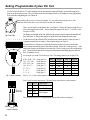
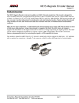
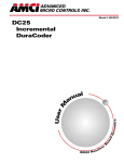
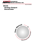
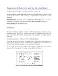
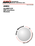
A D V A N C E D
M IC R O C O N T R O L S
IN C .
DURACODER® USER MANUAL
ABSOLUTE OUTPUT VERSION
Electrical Specifications
Code Format:
Gray, Binary: 4096 counts max.
BCD: 4000 counts max.
Frequency Response: 125 kbits/sec min.
Output Configuration: Open Collector Sink.
5 to 24 Vdc out. Available with or
without a 10 KΩ pull-up resistor.
Open Collector Source.
5 to 24 Vdc out.
Drive Capability:
15 mA Sink or Source max.
Power Requirements: 4.75 to 26.4 Vdc
1.5W max.
Environmental Specifications
Housing:
Connector:
Operating Temp:
Humidity:
Shock:
Vibration:
NEMA 4 rated
MS "R" style
-40° C to 85° C
98% RH, noncondensing
50g, 11 mSec duration
20g, 5 to 2000 Hz
DC25
Mechanical Specifications
Shaft Diameter:
Shaft Loading:
Starting Torque:
Moment of Inertia:
Weight:
3/8", 1/4", or 10mm stainless
Axial 15 lb, Radial 30 lb
1.5 oz.in. @ 25° C
4 oz-in-sec2
1 lb
– B
HOUSING
SHAFT DIA.
F = Square Flange
S = 2.5" Dia. Servo Mount
1 = 0.375" Dia.
2 = 10 mm Dia.
3 = 0.250" Dia.
BEARING SEAL
Notes:
1) Level Update - The outputs
continuously update when a
logic '1' voltage is supplied
to the input pin.
2) Edge Update - The outputs
update only when the voltage
supplied to the input pin
makes a transition.
3) Mx - Multiplex option.
Outputs are passive when
the input pin is pulled to GND.
Allows multiple DuraCoders
on single input wires.
A) Gated Z - Z Pulse is active for
1/2 Cycle of B.
A
B
DURACODER TYPE
STANDARD PRODUCT
A = Absolute Parallel
Level Update1
N = Incremental, GatedA
V = Analog Voltage
C = Analog Current
S = Absolute Serial Data
ALSO AVAILABLE
B = Absolute Parallel
Edge Update2
L = Absolute Parallel
Level Update 1, Mx3
E = Absolute Parallel
Edge Update2 , Mx3
M = Incremental, UngateB
Single Ended output only.
T = Incremental, GatedA
2-Speed ResolverC
F = Incremental, GatedA
4-Speed ResolverD
Z
B) Ungated Z - Z Pulse is active for
1 Cycle of A.
A
B
Z
C) When using a two speed resolver,
the Z Pulse is active twice per
rotation.
D) When using a four speed resolver,
the Z Pulse is active four times
per rotation.
MATING CONNECTORS:
All mating connectors are now
ordered as seperate line items.
All Absolute DuraCoders
...................................... MS-19
All Analog DuraCoders
................................... MSD-10
All Incremental DuraCoders
w/o Differential Output . MS-16
Incremental DuraCoders w/
Differential Output ..... MSD-10
OUTPUT SCALING
IF DURACODER TYPE = A,B,E,L
1 = 1,024 Gray Code
2 = 1,024 Natural Binary
3 = 4,096 Gray Code
4 = 4,096 Natural Binary
5 = 360 BCD
6 = 1000 BCD
7 = 3600 BCD
8 = Programmable
Resolution and Output Code
B0002 to B4096
Factory Set Binary
D0002 to D4000
Factory Set BCD
G0002 to G4096
Factory Set Gray
IF DURACODER TYPE = M, N
PRGM - Field Programmable
0002 to 1024 - Factory Set
IF DURACODER TYPE = T
PRGM - Field Programmable
0004 to 2048 † - Factory Set
†
Multiples of 2 only.
IF DURACODER TYPE = F
PRGM - Field Programmable
0008 to 4096 ‡ - Factory Set
‡
Multiples of 4 only.
IF DURACODER TYPE = V
1 = 0 to 5 Vdc
2 = 0 to 10 Vdc
3 = ± 5 Vdc
4 = ± 10 Vdc
5 = -5 to 0 Vdc
6 = -10 to 0 Vdc
IF DURACODER TYPE = C
1 = 4 to 20 mA
2 = 0 to 20 mA
3 = 0 to 24 mA
IF DURACODER TYPE = S
1 = CAN
2 = DeviceNet
3 = SDS
20 Gear Drive, Plymouth Industrial Park, Terryville, CT 06786
Tel: (860) 585-1254 Fax: (860) 584-1973
CONNECTOR
S = Side
E = End
OUTPUT CONFIGURATION
IF DURACODER TYPE = A, B, E, L
HIGH TRUE OUTPUTS
A = Current Source, Single Ended, 24 Vdc Max.
B = Current Sink, Single Ended, 24 Vdc Max.
C = Current Sink, Single Ended,
with 10KΩΩ Pull Up Resistor.
LOW TRUE OUTPUTS
F = Current Source, Single Ended, 24 Vdc Max.
G = Current Sink, Single Ended, 24 Vdc Max.
H = Current Sink, Single Ended,
with 10KΩΩ Pull Up Resistor.
IF DURACODER TYPE = M, N
A = Current Source, Single Ended, 24 Vdc Max.
B = Current Sink, Single Ended, 24 Vdc Max.
C = Current Sink, Single Ended,
with 2.2KΩ Pull Up Resistor.
D = Differential Line Driver
5 Vdc Output Only.
Not available with DuraCoder Type M.
E = Current Source, Single Ended,
with 2.2K Ω Pull Down Resistor.
IF DURACODER TYPE = V, C
K = 360° Output Signal Period
L = 180° Output Signal Period
M = 90° Output Signal Period
N = 45° Output Signal Period
Setting Programmable Cycles Per Turn
If your DuraCoder has an "8" in the ninth digit of the part number (Output Scaling), use the following procedure to set the counts per turn. The procedure involves removing the back cover, adding or removing jumpers
from a header, and putting the cover back on.
Remove these three screws to access the header. Use care when removing the cover. End
connector DuraCoders have wires from the PC board to the connector.
There are two headers on the DuraCoder. (See figure 2) Change the jumpers on the first 14
pins of the larger header (STR1). Do not change the jumpers on pins 15-17 of STR1 or the
two pins of STR2.
The jumpers are notched on one end. Make sure the jumper is placed on the header notched end
first. (See figure 3.) Placing these jumper on upside down may damage the metal wipers.
Fig.1 Back Plate
1
3
5
7
9
1 1
1 3
1 5
1 7
If you don't have a calculator to perform the decimal to binary conversion, use the table
below to determine which jumpers should be installed. Start with (Counts per Turn) - 1 and
subtract the largest possible number from the table. Place a jumper across the coresponding
pins. Continue subtracting the next largest possible number and adding jumpers until you
have a remainder of zero.
S T R 1
1
3
5
7
9
1 1
1 3
1 5
Use the first twelve pins of header STR1 to set the binary number equal to (Counts per Turn) - 1.
A jumper across the pins sets a logic 1, Removing the jumper sets a logic 0.
1 7
S T R 1
For example, you want 2790 Counts per Turn. The jumpers must be set to equal 2789.
2
1
2789 - 2048 = 741
741 - 512 = 229
229 - 128 = 101
101 - 64 = 37
37 - 32 = 5
5-4=1
1-1=0
S T R 2
2
1
S T R 2
Fig. 2 Header Locations
(Jump pins 12)
(Jump pins 10)
(Jump pins 8)
(Jump pins 7)
(Jump pins 6)
(Jump pins 3)
(Jump pins 1)
JMP. #
12
11
10
9
8
7
Pins 11, 9, 5, 4, 2 have their jumpers removed.
Weight
2048
1024
512
256
128
64
JMP. #
6
5
4
3
2
1
Weight
32
16
8
4
2
1
Pins 13 and 14 set the output code. The table below shows how to set the jumpers.
Pin 13 Pin 14
N O T C H
ON
ON
ON
OFF
OFF
ON
OFF
OFF
Output Type
Binary Output
Gray Code Output
BCD Output
The remaining jumpers are configured at the factory and need not be changed.
Fig. 3
Jumper Orentation
2
Outline Drawings
( ) = D im e n s io n s in m illim e te r s
2 .5 0 " (6 3 .5 )
0 .4 8 "
T o ta l c le a r a n c e
n e e d e d fo r
m a tin g
0 .3 0 0 " (7 .6 2 )
S H A F T D IA .
S E E N O T E 1
(1 2 .2 ) m a
o f 3 .5 "(8
re m o v a l
c o n n e c to
x .
9 )
o f
r.
Connector Pin Designations
MS3112E14-19P
D C 2 5
S e r v o M o u n t
E n d C o n n e c t o r
2 .3 1 "
(5 8 .6 4 )
M
0 .9 0 0 " (2 2 .8 6 )
0 .8 5 0 " (2 1 .5 9 )
1 .2 5 0 " (3 1 .7 5 )
1 .2 4 9 " (3 1 .7 2 )
0 .1 0 " (2 .5 )
0 .1 0 " (2 .5 )
3 .0 0 " (7 6 .2 ) m a x .
# 8 - 3 2 U N F - 2 B . 0 .1 8 " ( 4 .6 ) m in d e p th . S ix
p la c e s , 6 0 ° a p a r t o n a 1 .8 7 5 " ( 4 7 .6 3 ) B .C .
M S 3 1 1 2 E -1 4 -1 9 P
C o n n e c to r
L
N
K
U
J
0 .3 0 0 " (7 .6 2 )
D C 2 5
2 .3 1 "
0 .9 0 0 " (2 2 .8 6 )
0 .8 5 0 " (2 1 .5 9 )
CL
(2 6 .2 1 )
ty p .
S H A F T D IA .
S E E N O T E 1
1 .0 3 2 "
ty p .
CL
0 .4 8 "
T o ta l c le a r a n c e
n e e d e d fo r
m a tin g
0 .3 0 0 " (7 .6 2 )
(2 6 .2 1 )
If S h
M
If S h
M
If S h
M
(1 2 .2 ) m a x .
o f 3 .5 "(8 9 )
re m o v a l o f
c o n n e c to r.
1
a f
a x
a f
a x
a f
a x
t D
. D
t D
. D
t D
. D
ia
ia
ia
ia
ia
ia
m e
. =
m e
. =
m e
. =
te
0
te
9
te
0
r
.3
r
.9
r
.2
D ig
7 4 7
D ig
9 3 m
D ig
4 9 7
it =
",
it =
m
it =
",
1 :
M in
2 :
, M
3 :
M in
(0
. D
(1
in .
(0
. D
.3
ia
0
D
.2
ia
7 5
. =
m m
ia .
5 0
. =
" N o m in
0 .3 7 4 4
N o m in
= 9 .9 8 5
" N o m in
0 .2 4 9 2
"
"
a l)
a l)
m m
a l)
F la n g e M o u n t
E n d C o n n e c t o r
0 .9 0 0 " (2 2 .8 6 )
0 .8 5 0 " (2 1 .5 9 )
2 .5 0 " (6 3 .5 ) d ia .
2 .6 5 "
N O T E
D C 2 5
2 .6 5 "
(6 7 .3 )
1 .2 5 0 " (3 1 .7 5 )
1 .2 4 9 " (3 1 .7 2 )
F
(6 3 .5 )
0 .1 0 " (2 .5 )
0 .1 0 " (2 .5 )
2 .7 0 " (6 8 .6 ) m a x .
e s , 6 0 ° a p a rt
5 " (4 7 .6 2 ) B .C .
0 .2 1 8 " (5 .5 4 ) d ia .
F o u r p la c e s .
G
E
2 .5 0 "
S e r v o M o u n t
S id e C o n n e c t o r
(5 8 .6 )
N F -2 B .
S
D
M S 3 1 1 2 E -1 4 -1 9 P
C o n n e c to r
S H A F T D IA .
S E E N O T E 1
.6 ) m in . d e p th .
R
(3 6 .3 )
0 .3 0 0 " (7 .6 2 )
# 8 -3 2 U
0 .1 8 " (4
S ix p la c
o n 1 .8 7
C
1 .4 3 " s q .
a x .
c e o f 3 .5 "(8 9 )
m o v a l o f
c to r.
2 .4 7 " (6 2 .7 )
m a x .
1 .0 3 2 "
V
H
0 .9 5 " (2 4 .1 ) m
T o ta l c le a r a n
n e e d e d fo r re
m a tin g c o n n e
B
P
T
( ) = D im e n s io n s in m illim e te r s
1 .2 5 0 " (3 1 .7 5 )
1 .2 4 9 " (3 1 .7 2 )
A
.2 5 0 " (6 .3 5 )
M S 3 1 1 2 E -1 4 -1 9 P
C o n n e c to r
2 .9 5 " (7 4 .9 ) m a x .
( ) = D im e n s io n s in m illim e te r s
(6 7 .3 )
( ) = D im e n s io n s in m illim e te r s
1 .4 3 " s q .
0 .9 5 " (2 4 .1 ) m
T o ta l c le a r a n
n e e d e d fo r re
m a tin g c o n n e
2 .4 7 " (6 2 .7 )
m a x .
(3 6 .3 )
a x .
c e o f 3 .5 "(8 9 )
m o v a l o f
c to r.
M S 3 1 1 2 E -1 4 -1 9 P
C o n n e c to r
0 .3 0 0 " (7 .6 2 )
2 .6 5 "
(6 7 .3 )
CL
S H A F T D IA .
S E E N O T E 1
D C 2 5
1 .2 5 0 " (3 1 .7 5 )
1 .2 4 9 " (3 1 .7 2 )
1 .0 3 2 "
F la n g e M o u n t
S id e C o n n e c t o r
2 .5 0 "
(6 3 .5 )
(2 6 .2 1 )
ty p .
1 .0 3 2 "
(2 6 .2 1 )
CL
2 .6 5 " (6 7 .3 )
ty p .
0 .2 1 8 " (5 .5 4 ) d ia .
F o u r p la c e s
0 .9 0 0 " (2 2 .8 6 )
0 .8 5 0 " (2 1 .5 9 )
.2 5 0 " (6 .3 5 )
2 .6 5 " (6 7 .3 ) m a x .
3
Connector Pinout
Absolute Output Electrical Connections
Output Connector: MS3112E14-19P
FUNCTION
PIN NO.
GRAY
CODE
NATURAL
BINARY
BCD
(8421)
A
G(0)
20
1
B
G(1)
21
2
G(2)
22
4
G(3)
23
8
G(4)
4
10
5
20
6
C
D
E
F
G(5)
2
2
G
G(6)
2
40
H
G(7)
27
80
J
G(8)
28
100
K
G(9)
9
2
200
L
G(10)
2 10
400
M
G(11)
11
800
N
Not Used
Not Used
1000
P
Not Used
Not Used
2000
R
Direction
Direction
Direction
S
Case GND
Case GND
Case GND
T
DC Return
DC Return
DC Return
U
Latch
Control
Latch
Control
Latch
Control
V
+DC Input
+DC Input
+DC Input
2
Pin U: Latch Control - This pin controls how often
the outputs update and should be used to freeze
the outputs before the output data is read. The
input is configured at the factory to be either
level or edge sensitive.
Level Sensitive - A Logic 1 voltage on this pin will
update the outputs within 40 µSec. The output
data will then update continuously every 8 µSec.
A Logic 0 voltage will freeze the output data
within 10 µSec. If this input is low when power
is applied to the DuraCoder, the outputs will be
all low until the first positive transition.
40 µSec
LATCH
CONTROL
DATA
BITS
Edge Sensitive - A 0 p 1 or 1 p 0 transition on this
pin will update the outputs within 40 µSec. The
outputs will then freeze until another vaild
transition. Therefore, the transitions must be a
minimum of 40µSec apart. (12.5 kHz maximum
at 50% duty cycle.)
All of the outputs will be in a zero state on
power up and will remain in this state until the
first transition occurs. Position output will not be
valid until this transition.
40 µSec
Pin R: Direction - This pin controls which direction the
shaft must turn to increment the position data. With this
pin open circuit, position data increases with CCW
rotation (looking at the shaft). Connecting this pin to
Pin T, (DC Return), forces the position to increase with
CW rotation (looking at the shaft).
NOTE: Connection to Pin T (DC Return) must
be done at the DC25 Connector. Do not
connect at the other end of the cable.
4
10 µSec
40 µSec
LATCH
CONTROL
DATA
BITS
Input Logic 1: 3Vdc to +DC Input or Open
Circuit.
Input Logic 0: 0 to 1 Vdc.
NOTE: If you choose not to use this input, leave
it floating or connect it to +DC Input. Connecting
it to DC Return will freeze the outputs.
Output Specifications
Source Output Configuration
Output Options A, F
Max. Leakage Current:
5 µA
Max. ON State Current:
15 mA
Max. ON State Resistance: 100 Ω (1.5Vdc drop
across driver @ 15mA)
Output Option F
Output Option A
High True Output: Driver turns on for logic 1
Driver turns off for logic 0
Low True Output: Driver turns off for logic 1
Driver turns on for logic 0
Sink Output Configuration
Output Options B, C, G, H
Max. Leakage Current:
5 µA
Max. ON State Current:
15 mA
Max. ON State Resistance: 100 Ω (1.5Vdc drop
across driver @ 15mA)
Output Option B
Output Option C
High True Output: Driver turns off for logic 1
Driver turns on for logic 0
Output Option G
High True Output: Driver turns off for logic 1
Output pulled high with
10KΩ pull-up resistor.
Driver turns on for logic 0
Output Option H
Low True Output: Driver turns on for logic 1
Driver turns off for logic 0
Low True Output: Driver turns on for logic 1
Driver turns off for logic 0
Output pulled high with
10KΩ pull-up resistor.
Notes
1) Use an overall shielded cable to connect the DuraCoder to your electronics. The exact cable will depend
on the number of conductors needed and will vary from application to application. The shield of the
cable must be connected as close as possible to the power supply earth ground. DO NOT connect both
ends of the shield to earth ground. This can form a ground loop that may affect the operation of the
DuraCoder.
2) The DuraCoder case must be connected to Earth Ground. This is usually accomplished through its
mounting. If not properly grounded through its mounting, a wire from PIN S must be connected to an
Earth Ground point as close as possible to the DuraCoder. DO NOT connect PIN S to the cable shields.
This can form a ground loop that may affect the operation of the DuraCoder.
3) Use a regulated power supply with its voltage output in the range of 7 to 24Vdc. If the cable length is
less than 30 feet, a power supply of 5 to 24Vdc can be used.
DO NOT connect or disconnect the DuraCoder from its MS connector while power
is applied. Under limited circumstances, damage to the DuraCoder may result.
5
Important User Information
The products and application data described in this manual are useful in a wide variety of different applications. Therefore, the
user and others responsible for applying these products described herein are responsible for determining the acceptability for
each application. While efforts have been made to provide accurate information within this manual, AMCI assumes no responsibility for the application or the completeness of the information contained herein.
UNDER NO CIRCUMSTANCES WILLADVANCED MICRO CONTROLS, INC. BE RESPONSIBLE OR LIABLE FORANY
DAMAGES OR LOSSES, INCLUDING INDIRECT OR CONSEQUENTIAL DAMAGES OR LOSSES,ARISING FROMTHE USE
OFANY INFORMATION CONTAINEDWITHIN THIS MANUAL, ORTHE USE OFANY PRODUCTS OR SERVICES REFERENCED HEREIN.
No patent liability is assumed by AMCI, with respect to use of information, circuits, equipment, or software described in this
manual.
The information contained within this manual is subject to change without notice.
® DuraCoder is a registered trademark of AMCI. AMCI is a registered trademark, and the AMCI logo is a trademark of
Advanced Micro Controls, Inc.
Standard Warranty
ADVANCED MICRO CONTROLS, INC. warrants that all equipment manufactured by it will be free from defects, under normal
use, in materials and workmanship for a period of eighteen months. Within this warranty period, AMCI shall, at its option, repair
or replace, free of charge, any equipment covered by this warranty which is returned, shipping charges prepaid, within eighteen
months from date of invoice, and which upon examination proves to be defective in material or workmanship and not caused by
accident, misuse, neglect, alteration, improper installation or improper testing.
The provisions of the “STANDARD WARRANTY” are the sole obligations of AMCI and excludes all other warranties expressed or implied. In no event shall AMCI be liable for incidental or consequential damages or for delay in performance of this
warranty.
Returns Policy
All equipment being returned to AMCI for repair or replacement, regardless of warranty status, must have a Return Merchandise
Authorization number issued byAMCI. Call (860) 585-1254 with the model number and serial number (if applicable) along with a
description of the problem. A “RMA” number will be issued. Equipment must be shipped to AMCI with transportation charges
prepaid. Title and risk of loss or damage remains with the customer until shipment is received by AMCI.
24 Hour Technical Support
24 Hour technical support is available on this product. If you have internet access, start at our website, www.amci.com.
Product documentation and FAQ’s are available on the site that answer most common questions.
If you require additional technical support, call (860) 583-7271. Your call will be answered by the factory during regular
business hours, Monday through Friday, 8AM - 5PM EST. During non-business hours an automated system will ask you to
enter the telephone number you can be reached at. Please remember to include your area code. The system will page an
engineer on call. Please have your product model number and a description of the problem ready before you call.
Revision History
This manual, 940-0D041 replaces 940-0D040. Its first issue date was 04/04/2005. It improves the outline drawings and adds
powerup information on the latch control input.
AMCI manuals are constantly evolving entities. If you notice any errors or would like to comment on the contents of this
manual please call or faxAMCI Technical Documentation. Tel. (860) 585-1254 Fax. (860) 584-1973
AMCI – Leaders in Advanced Control Products