1
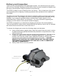
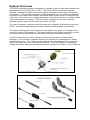
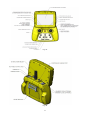
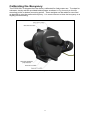
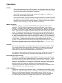
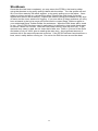
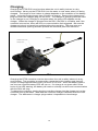
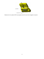
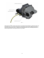
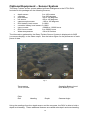
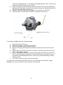
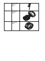
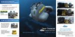
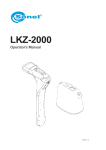
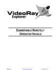
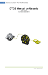
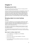
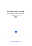
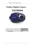
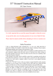
DTG2 User Manual Version 1.0 - 2013 01-2013-01-01 to 01-2013-01-100 Warning WARNING: • Never operate your DTG2 in the presence of unaware swimmers or divers. • Always use a Personal Flotation Device (PFD) and obey any laws pertaining to the operation of your launch vehicle. NOTE: Because of the sharp running hardware included with this product, we do not recommend a rubber blow up raft. • The DTG2 running hardware is very sharp. Be very careful when working on and around the parts. • While the motor is running pay close attention to the propeller. Do not come in contact with the propeller at any time the system is turned on or serious injury will result. • Deep Trekker products are to be used by people 16 years of age and over. 2 Index Safety Precautions………………...................................................................4 Manual Specifications and Description Changes………………………..….…5 Delivery and Inspection…………………………………………………………...6 System Overview……………………………………………………………..…...7 Calibrating the Buoyancy…………………………………………………………9 Start-up……………………………………………………………………………..10 Operation………………………………………………………………………..…11 Shutdown…………………………………………………………………..………13 Charging……………………………………………………………………………14 Storage……………………………………………………………………………..16 Transporting…………………………………………………………………….…17 Optional Equipment – Sensor System………………………………………….19 Optional Equipment – Two Function Grabber………………………………….21 Optional Equipment – DVR…………………...………………………………….23 Maintenance…………………………………………………………….…………26 Troubleshooting.…………………………………………………………………..27 Parts and Service…………………………………………………………………29 Warranty………..………………………………………………………………….32 3 Safety Precautions • Never, ever, attempt to swim after a stalled DTG2. Do not get in the water for any reason to retrieve your DTG2. Return the DTG2 by gently pulling it back to the boat by the tether. In a case where the tether is snagged or severed, contact a certified diver to perform the retrieval for you. • Deep Trekker products are to be used by ages 16 and over. • Do not touch the propeller when the motor is spinning. Pay equally close attention to items such as loose clothing, shirtsleeves, ties, scarves, long hair or anything that may become entangled in the spinning propeller. If your fingers, hands, etc. come in contact with the spinning propeller, you may be severely injured. •Keep your launching and piloting area tidy and your tether neatly rolled to avoid tripping while operating the DTG2. • The speed and mass of this DTG2 ROV can inflict property damage and severe personal injury if a collision occurs. Never run this ROV in the presence of unaware swimmers or boaters or where the possibility of collision with people or property exists. • Be aware of the danger around you, including weather, and obey all applicable laws while using standard water safety procedures. 4 Manual Specification and Description Changes 5 Delivery and Inspection Thank you for purchasing the DTG2 exploration system. We want the time you spend with your new remotely operated vehicle (ROV) to be fun and successful so please read the entire manual before using this product for the first time. The DTG2 is ready for use as delivered from the factory. The unit has been fully tested and inspected prior to shipping, including a pressure test equivalent to the maximum dive depth. The ROV and controller batteries will be low for shipping reasons and will require a full charge prior to use. Fully inspect your ROV to ensure it has not been damaged during shipping. If you suspect a problem please contact Deep Trekker support or your authorized Deep Trekker Dealer for assistance. For more information regarding the charging, see the section in the manual entitled Charging. The DTG2 is shipped to you with the two shipping set screws in the locked position. This ensures that the rough motions associated with the delivery service do not damage the internal frame and the servo motor that turns it. To release the shipping set screws the following steps must be taken. 1) 2) 3) Using a high pressure garden hose, wash the head of the set screw to ensure all sand and foreign partials that have the potential to compromise the o-ring seal are removed. Rotate ROV upside down with the handles facing downward. This will ensure it does not rotate until the screw is completely backed out. While in this position, turn both set screws using a flathead screwdriver counter-clockwise until the set screw heads are firmly against the cover plate. ***DO NOT REMOVE THE SHIPPING SET SCREW UNDER ANY CIRCUMSTANCES. THIS OPENS UP THE SEALED UNIT AND WILL LEAD TO IMMEDIATE FAILURE IF SUBMERGED*** Slowly rotate ROV to its level position. Fig. 1 6 System Overview The DTG2 exploration system is designed to operate in fresh or salt water between the temperatures of 0C [32F] to 45C [113F]. This unique ROV incorporates onboard batteries, allowing the tether to be much smaller and lighter than a tether designed to carry power. The controller replicates a traditional game pad. No additional console is required on the surface which makes the system easy for one person to transport and travel with. Since there is no voltage drop down a long tether, there is no need to utilize a high and dangerous voltage. The ROV system operates at 19.2 VDC, and the separate system inside the controller is less than 14 VDC. The use of magnetic couplers means that there is no dynamic shaft seal on board the DTG2. This feature dramatically increases reliability and decreases maintenance. The patent pending pitch control aims the outer shell to any angle +/- 90 degree from center for a total of 180 degrees. This system which works entirely from within the hull eliminates the requirement of a third thruster and further increases reliability. The ROV and tether are 100% waterproof and should not take on water unless damaged. The controller is splash resistant, but should not be submerged or power washed at any time. The viewing systems offered are not waterproof in any way and need to be taken care of in outdoor environments. The ROV charger and controller charger are indoor products that should never be operated near water or wet conditions. Fig. 2A Fig. 2B 7 Fig. 3A Fig. 3B 8 Calibrating the Buoyancy The DTG2 ROV is shipped from the factory calibrated for fresh water use. To adapt for saltwater, simply add the provided ballast plates as shown in Fig 4 evenly to the top mounting points or bottom mounting points. These weights can be added or removed as desired to gain the preferred buoyancy. It is most common to bias the buoyancy to a slightly positive setting. Fig. 4 9 Start-up Prior to operating the DTG2 system, ensure you have read the entire operator’s manual and fully understand it. Once fully charged remove the charger from the ROV and set it right side up on a secure surface. This is important because as soon as the system is active the pitch system will rotate to this level condition assuming that the pitch joystick is centered. Turn the controller on with the ON/OFF button. The controller and ROV will enter the boot sequence that should last no longer than 5 seconds. The video camera will come out of its downward park position and point forward. The camera and light are now safe to use. The thrusters can be activated in dry conditions for no more then 60 seconds at a time. The pitch system should not be activated until the DTG2 is in the water. Any dive should include a short inspection to ensure that everything is in order: 1) 2) 3) 4) 5) Check the thrusters for any debris that was left from the prior dive. Inspect the tether to ensure it has not been worn or breached in any way. Check for loose fasteners on the ROV. Check the connection between the window and side bodies to ensure it is sealed. Turn on the system and check functionality of the thrusters, lights and camera. Do not operate the pitch system while out of water. The lights can run indefinitely while the ROV is out of water, but the thrusters should not run for more then 60 seconds, as there is a waterproof bearing with a seal that relies on water for lubrication. Once the inspection is complete prepare to launch using the following steps as a minimum: 1) 2) 3) Inform anyone else nearby such as divers, swimmers or boaters that you are deploying the DTG2 and its tether. Only deploy if you have their approval. Ensure your launch and piloting area are clean. Ensure your tether is neat and ready to deploy. For a first trial run, choose a safe shallow and clear body of water that does not include obstacles capable of getting tangled in. There should be no wind or current present. Lower the DTG2 into the water by the stainless steel tether bracket across the back, or gently lower it in by the tether. Do not throw the DTG2 into the water for fear of striking an object. At this point it is advised to operate the ROV without the use of the camera and viewing system. Keep it near the surface for easy visibility and familiarize yourself with the controls. 10 Operation On/Off: The on/off button as shown in Fig 3 acts as an ON button when the ROV is off, and an OFF button when the ROV is on. Pressing the on button starts a boot sequence that will last about 3 seconds. If the ROV is turned off while diving, simply turn it back on. It does not have to be on dry land for a re-boot. If the controls have not been activated on the controller for several minutes the system will automatically shut down. This will shut down the controller and ROV, but not the video viewing system. Ensure you shut the viewing systems down manually or they will drain their batteries. Motion Controls: As shown in Fig 3. the motion of the DTG2 is accomplished with only 2 joysticks. The left joystick completely controls the thruster in an intuitive manner. Forward on the joystick is forward on the ROV. Back on the joystick is reverse on the ROV. Right and left on the joystick are right and left on the ROV. The patent pending pitch system rotates the entire outer body up and down. This feature transforms the thrust motion from the primary thrusters into vertical motion. Like an airplane, if you point the jets up, it will climb, if you point them down it will descend. The DTG2 is essentially the same thing in water, except because it is the same weight as water (if you the operator calibrated it correctly) it will remain at the same depth until the thrusters move it up or down. Rotating the pitch system is accomplished with the right joystick. Forward descends into the water and pulling back ascends. Right and left on this right joystick do not affect the ROV motion in any way, they are used for grabber rotate which is optional equipment. Camera: The camera and lights are controlled by the push buttons as shown in Fig 3. The camera track button will quickly reposition your camera to point in the same direction the thrusters are pointing. This feature is helpful because most often you want to look ahead when you are driving. It is helpful to have objects other than the open water in the field of vision of the camera. This will give you your bearings on what the ROV is doing. Descending and Ascending: The DTG2 is capable of diving to great depths. Ensure on your decent that you do not crash into any sharp objects as you approach the bottom. While descending, ensure your camera is pointing down in order to show you the approach, and likewise on your accent, ensure the camera is pointing up to show you the possibility of an object, ie a boat hull in the way. The easiest way to ensure your camera is pointing in the correct position is to momentarily press the camera track button, while pitching to reposition your camera forward in line with the thrusters. LED Indicators: Check the controllers LED indicators often. Frequently the low battery lights will turn on. When the ROV is low on batteries it will slow down considerably. Return it to the boat and charge it when safely indoors. When the low controller battery LED is flashing, you will have enough power to finish the dive, but must remember to charge it before the next. If the controller 11 batteries are not charged, the LED will eventually completely turn on, and it will stop sending data to the ROV, rendering the system unusable. Once the system is safely back indoors plug the controller charger into the controller charge port as shown in Fig 3. If the thruster error LED light is on, return the ROV to the boat and turn the system off. Inspect the propellers and magnetic couple for binding objects. Removal of the guards and propeller may be required. Once the debris is removed turn on the system again and test the thrusters in and out of the water. If the thruster error LED again turns on, contact Deep Trekker support or your authorized Deep Trekker Dealer for assistance. If the pitch stall LED turns on simply press the reset thrusters/pitch button on the controller. The pitch can be stalled by excessive pull on the tether, or by trying to pitch the system out of the water. If the pitch stall LED again turns on contact Deep Trekker support or your authorized Deep Trekker Dealer for assistance. The no communication LED will turn on when the ROV is extremely low on batteries, or not plugged into the tether. If a full battery charge does not fix the problem, contact Deep Trekker support or your authorized Deep Trekker Dealer for assistance. See also the trouble shooting guide portion of the manual. The second function of the no communication LED is to warn of water ingress into the ROV hull. The communication LED will flash quickly if water is sensed. During this occurrence the ROV will become immobile, and you must pull it out of the water as quickly as possible and contact Deep Trekker support or your authorized Deep Trekker Dealer for assistance. Tether: It is advised to have an assistant managing the tether as the ROV demands more let into the water, or pulled back out of the water. Leaving too much tether in the water will cause excess drag on the DTG2, and not having enough will restrict the ROV manoeuvrability. The tether needs to be closely observed while in use as it poses a threat to swimmers and divers as well as boaters. Do not bend the tether in a radius of 75mm (3”) or less. Do not kink the tether. Never drag the tether over a rough or sharp surface. This will quickly wear the outer protective jacket and eventually flood the cable. Do not step on or drive over the tether. Crushing the tether in any way may damage it in a fashion that is non-repairable. Entanglement: Take extreme care in conditions that increase the chance of the tether being tangled. If the DTG2 does get tangled, assess the situation with the camera and manoeuvre the ROV appropriately to become free. Failing that, the tether can be pulled on lightly with a maximum force of 27 kilograms (50 pounds) to become free. If that fails it is advisable to find a certified diver who can manually untangle the system. Never dive in the water yourself to perform this manoeuvre. Under no circumstances is a lost or damaged system warrantable. 12 Shutdown Once the dive has been completed, you may return the DTG2 to the boat by either using the thrusters or by gently pulling it back with the tether. Turn the system off and lift it out of the water by the tether support, or by gently pulling up on the tether. Once safely on shore and set on a sturdy flat surface, inspect the outer body for foreign objects and remove as necessary. Inspect the interior through the window for any sign of water and the inner window for fogging. If you see either of these problems you may have a breach in the hull at some point and need to contact Deep Trekker support or your authorized Deep Trekker Dealer for assistance. Wipe the ROV down with a towel or rag. If the DTG2 has been used in salt water it is advised to rinse it with fresh water to ensure it does not corrode. After the fresh water rinsing, wipe the ROV dry. If the optional carry case is used, do not close the lid after use. Allow 1-2 hours for the ROV and tether to dry off 100% prior to sealing the case shut. Any significant amount of moisture left in the case will promote corrosion. If the DTG2 has been launched from a boat, stow it safely before moving on. Do not let the ROV bounce around the boat. 13 Charging Charging the DTG2 ROV must be done when the unit is safely indoors in a dry environment. Never put the DTG2 ROV into the water or near water when it is being charged. The length of time it takes to charge depends on the condition of the battery packs. It should not take longer than 3.5 hours to charge. Remove the charge port plug and insert the charger plug into the ROV. The charger is charging when the LED on the charger is red. Charging is complete when the green LED appears on the charger. When the charger is plugged into the ROV, the ROV is unusable, and if the controller is turned on, there will be a no communication fault triggered. Be sure the charge port plug is returned into position before the next dive. The plug acts as a double seal at this opening and also protects the electrical pins from corrosion. Fig. 5 Charging the DTG2 controller must be done when the unit is safely indoors in a dry environment. The controller is powered by a separate built-in battery pack that will require a charge approximately every 10 hours of run time. When the battery pack is low, the low controller battery LED will turn on. If a charge is not given within a few hours of the LED warning, the battery will reach a critically low level and communication with the ROV will stop. To charge the controller, simply plug the controller charger into the charge port on the controller next to the tether. Note that the controller charger is different from the ROV charger. The difference in charger plugs makes it impossible to interchange. 14 Fig. 6 Batteries for the optional DVR are separate and will need to be charged as required. 15 Storage Store your ROV in a location that is safe from animals or insects that are capable of causing damage to the tether. One small hole in the tether will cause it to flood and could lead to a communication failure between the controller and ROV. Store in dry locations between the temperatures of -20C [-4F] and 40C [104F] out of direct sunlight. Storing in climates out of this range will lead to premature battery failure. It is recommended to charge the battery at least once every 6 months if the unit is not being used. If the ROV is stored in a sealed compartment such as the optional carry case offered by Deep Trekker Inc., the ROV and tether must be left to dry off 100% prior to sealing the case shut. Any significant amount of moisture left in the case will promote corrosion. 16 Transporting ***It is important to store and transport your DTG2 in a fashion that does not rock the pitch system back and forth. This will cause premature failure because it is working the gear motor and gear train. This sort of failure is 100% unwarrantable. An easy way to prevent the pitch system from rocking back and forth is to stow the ROV upside down such that the internal frame is resting against the mechanical stops located inside the hull. *** For instances where the DTG2 cannot be safely stored in the upside down position such as during air travel or very rough boat travel, the use of the 2 shipping set screws may be required. These screws are found on the rear of the ROV behind the tether bracket. Their purpose is to mechanically hold the internal framework so that it is unable to move. To properly use the set screws, the following steps must be taken: 1) 2) 3) Using a high pressure garden hose, wash the heads of the set screws to ensure all sand and foreign partials that have the potential to compromise the o-ring seal are removed. Slowly rotate ROV backwards (as if to ascend) to position the internal frame against the stops. While in this position, turn the set screws using a flathead screwdriver clockwise until they are firmly against the internal frame and holding it in this position. In this configuration the ROV is unusable and should not be turned on. If the ROV is mistakenly turned on, the pitch stall error LED will appear because the servo motor cannot override this mechanical connection. To release the shipping set screw the following steps must be taken. 1) 2) 4) Using a high pressure garden hose, wash the head of the set screw to ensure all sand and foreign partials that have the potential to compromise the o-ring seal are removed. Rotate ROV upside down with the handles facing downward. This will ensure it does not rotate until the screw is completely backed out. While in this position, turn both set screws using a flathead screwdriver counter-clockwise until the set screw heads are firmly against the cover plate. ***DO NOT REMOVE THE SHIPPING SET SCREW UNDER ANY CIRCUMSTANCES. THIS OPENS UP THE SEALED UNIT AND WILL LEAD TO IMMEDIATE FAILURE IF SUBMERGED*** Slowly rotate ROV to its level position. It is advised to only use the shipping screw when absolutely necessary. Overuse can lead to a worn o-ring and which in turn leads to a breach in the hull. Shifting the set crew in or out when debris such as sand is present in the cavity will lead to premature o-ring failure. 17 Fig. 7 Although the DTG2 needs to be stored in moderate temperatures as outlined under the Storage section, it can be transported in climates as low as -40C [-40F] for periods of time not exceeding 24 hours. Special care must be taken when handling the tether in these temperatures as the jacket will be very brittle. 18 Optional Equipment – Sensor System The Deep Trekker sensor system adds significant intelligence to the DTG2 ROV. Included in this package are the following sensors; depth sensor compass pitch sensor roll sensor camera angle sensor ROV battery level sensor controller battery level sensor turns counter ROV hour counter Water temperature 0 to 100 meters 0 to 360 degrees -85 to +85 degrees -85 to +85 degrees -105 to 105 degrees 0-100% 0-100% -32000 to +32000 turns 0 to 32000 hours -20 to 80 Celsius The information gathered by the Deep Trekker Sensor System is displayed via OSD (on-screen-display) to the video output. See the below figure for the placement of each piece of data. Fig. 8 Temperature Turns Counter Pitch Roll Controller Battery Level ROV Battery Level Heading Depth Camera Angle Using the readings from the depth sensor and the compass, the ROV is able to hold a depth and heading. These additional features are called auto-depth and auto-heading. 19 The auto-depth is activated by pressing the pitch joystick directly down. As soon as this is pressed, the ROV will record the current depth and attempt to hold it until the autodepth button (pitch joystick) is pressed again. The auto-depth feature is shown on screen by brackets around the depth reading. For example if the depth reading is <4m>, the auto-depth is active. If the depth reading is 4m, the auto-depth is not active. When the auto-depth is active, it adjusts the pitch angle of the ROV accordingly so that when the thrusters are in motion, the ROV will move to the desired level. If the thrusters are not active, the ROV will not automatically thrust itself to the desired level. The auto-heading is activated by pressing the thruster joystick directly down. As soon as this is pressed, the ROV will record the current heading and attempt to hold it until the auto-heading button (thruster joystick) is pressed again. The auto-heading feature is shown on screen by brackets around the heading reading. For example if the heading reading is <255>, the auto-heading is active. If the heading reading is 255, the auto-heading is not active. When the auto-heading is active, it adjusts the thrust level of each thruster accordingly. If the thrusters are not being activated by the operator, the auto-heading will automatically activate them accordingly in order to maintain a heading. For this reason, the auto-heading should not be activated while the ROV is on land or anywhere near people since the thrusters can turn unexpectedly. The compass, depth and water temperature sensors are located in the sensor pod, which is mounted directly behind the ROV. They are mounted remotely in order to keep away from the magnetic interference and heat generated by the ROV. Do not strike the sensor pod with anything or drive backwards into hard objects. Even with the pod mounted at the center rear of the ROV, slight magnetic interferences will be picked up that can skew the heading reading by +/- 15 degrees. This is an unavoidable dilemma when mounting a compass on a compact ROV. In addition to this, large metallic objects the ROV is working near can and will cause significant interference to the compass, which may or may not be noticeable. No error will be shown on screen, the heading reading indicated on the screen will be wrong. The turns counter records the number of turns an operator has made during the dive. It is a good idea to keep this number as close to 0 as possible and to return it to 0 before winding in the tether. If the ROV is powered OFF and ON again, the turns will reset to 0. Date and time readings are not included in the Deep Trekker sensor system. This must be added using the recording device. 20 Optional Equipment – Two Function Grabber The Deep Trekker two function grabber upgrades the DTG2 from an exploration-class micro ROV into a working-class micro ROV. The grabber is equipped with an open/close motion and a continuous bi-directional rotate motion. The open and close motion is activated using the two push buttons located at the front of the controller, opposite the camera up/down buttons. The rotate motion is activated using the pitch joystick X (horizontal) direction. The mechanical design of the two function grabber incorporates a self-locking feature. That is to say, once the claws are closed, they will not re-open unless the force is large enough to cause mechanical damage to the unit. This is a beneficial feature if the objects you are grabbing are very heavy. The down-side to this is that once the claws are locked closed, the rotate motion is also locked. The computer inside the grabber knows this and will slightly loosen the grip on the claws if the rotate is activated. This loosening is often enough to drop an object. The rotate should only be used to position the angle of the claws prior to grabbing. The grabber is fix-mounted to the exterior shell of the ROV. Due to the design of the DTG2 ROV and its ability to rotate the shell up or down, the two function grabber essentially gains an additional motion, allowing the user to grab below or above the ROV. This is a major advantage over a fixed shell ROV. The disadvantage is that the grabber can and will rotate into the view of the camera unexpectedly if the user is activating the pitch joystick. To help avoid this, and to lock the camera on the tips of the claw, the track-and-hold feature can be activated. This feature will force the camera to rotate with the motion of the exterior shell and grabber. To activate track-and-hold, press the camera track button and reset button for 4 seconds, until you see the pitch stall LED flash for 1 second. Once the LED flashes, track-and-hold is active. This only needs to be set once and the setting will be saved. To shut this off, use the same method. Now that this is configured, to turn it on, you simply press the camera track button. To turn it off, you press the camera track button again to release it. The maximum weight that the ROV can lift and self-maneuver with is very small. Generally, if you are retrieving a large or heavy object, the grabber is used to lock the ROV into it, and the user then retrieves the ROV and object by pulling it back using the tether. The maximum weight the grabber should carry is 50 lb. The tether is also rated for 50 lb or more. Please note that the weight of most objects will differ when it is pulled out of the water. Most will be much heavier in air. When the ROV is shut down after use, ensure the claws are fully closed and horizontal to the ground. Never attempt to close or rotate the claws by hand, this will cause damage to the unit. Do not attempt to rotate the claws while the ROV sits on dry land. The tips of the claws, if opened at all can cause the ROV to tip over. The dual shaft seals used on the grabber shaft are rated for underwater and dry air use. Inspect your grabber for foreign objects that may cause binding or seal damage. Do not use the grabber in sandy environments that may seize the rotate sleeve bearings directly behind the claws. The grabber can easily be removed if not in use. To do so, take the following steps; 1) 2) Shut down the ROV power. Unscrew the electrical connector leading into the rear of the ROV. Do not allow the plastic bulkhead mounted to the rear of the ROV to turn. This will 21 3) 4) 5) cause an immediate leak. If the plastic bulkhead appears loose, contact your authorized Deep Trekker Service center. Plug the exposed (and electrically active) terminals using the provided plug. Never leave these pins exposed to the water as they are electrically active at 20 VDC when the ROV is turned on. Remove the 4 pins that hold the grabber to the bottom of the ROV. Install the skis on each side of the ROV using the same 4 pins. Fig. 9 To install the grabber take the following steps; 1) 2) 3) 4) 5) 6) 7) Shut down the ROV power. Remove the skis on each side of the ROV. Mount the grabber using the same 4 pins. Remove the plug protecting the electrical terminals on the rear side of the ROV. Check the O-ring on the electrical connector connecting into the rear of the ROV. If damaged, replace. Plug in the grabber electrical connector and tighten by hand (not a wrench). Do not allow the plastic bulkhead mounted to the rear of the ROV to turn. If the plastic bulkhead appears loose, contact your authorized Deep Trekker Service center. Turn ROV on and ensure proper functionality. It is important to note that if the ROV power is not off during this procedure, major damage can occur to the ROV main computer circuit board. 22 Optional Equipment – DVR The Deep Trekker Portable DVR allows the live video stream from the ROV to be recorded to an SD card. Hardware Orientation Ⅰ. DVR 1. Power On/Off 2. Charge Led 3. Internal Microphone 4. AV Input & DC Out jack 5. Low Power LED 6. Record / Stop Button 7. Power On/Record LED 8. DC5V In Jack 9. USB Port 10. AV Out& Alarm In Jack 11. Reset Button 12. Lock Switch 13. Internal Speaker 14. SD Socket 15. IR Sensor 16. Down Button 17. Up Button 18. Enter Button 19. Esc Button 20. Menu Button Ⅱ. Remote Control 1. Record/Stop button 2. Up Button 3. Enter Button; 4. Down Button 5. LCD/TV Switch Button 6. Exit Button; 7. Menu Button 8. LCD Off Button; Ⅲ. Accessories 23 Setting Record Modes There are three work modes for recording: Record ----- for video and audio record, the record data will be saved in AVI files under the “Record Files” folder. Photo --- for still picture capture, the photos will be saved in JPG files under the “Photo Files” folder. Audio ----for only audio record, the record data will be saved in WAV files under “Audio Files” folder. This feature cannot be used with the DTG2 since the ROV has no audio capability. Fig. 10 Basic Operation 1. Image Size 2. Resoluton 3. Overwite On/Off 4. In/Out Microphone 5. Vibration On 6. SD card info 7. Battery Capacity 8. Date and Time Stamped 9. User ID 10. Mode Record Video 1) Charge the DVR battery for at least 3 hours before you begin recording. 2) Select a correct record mode for your task by setting work mode. 3) Ensure the SD card is properly installed into the DVR. 4) Connect the AV cable from the AV-in port on the DVR to the RCA video output jack on the ROV controller. 5) Slide the Record / Stop switch to “Rec” to start recording. 6) Complete the recording as desired up to the maximum length of video that the SD card can hold. 7) Slide the Record / Stop switch to “Stop” to end recording. Accessing the Videos for Playback on the DVR 1) Press the menu button. 2) Select Event Playback (camera reel icon). 3) Select Video Files. 4) Navigate to the desired file. 5) Press the select button to play back the video. 24 Fig. 11 Connecting with computer 1) Plug the USB cable into the DVR and an available USB port on your computer 2) The default password is 00000 for connecting to PC. 3) Navigate to the appropriate folder to access the recorded videos using Windows Explorer. The videos can be copied from the SD card onto your computer. The videos can also be deleted from the SD card using Windows Explorer in order to make room for new videos. 4) The DVR will power off automatically when you disconnect the USB from PC. 25 Maintenance The owner is responsible for the every day basic maintenance required in keeping the system in good working order. Ensure that the system is cleaned after every dive, and in the case of a salt water dive, ensure it is rinsed well in fresh water. Do not use any sort of a cleaning agent on the window other then fresh water. This high strength polymer window is sensitive to chemical attacks which will compromise the integrity of the structure. Never wash the ROV while it is being charged. The propeller guards and propeller can be removed only as required to pull out debris causing binding. Under no circumstance should the user unbolt a connection that includes an o-ring seal leading to the interior of the ROV. Warranty is void if these seals are breached. This level of service must be left to an authorized Deep Trekker Service center. The owner should not unplug the tether from the ROV unless absolutely necessary. 26 Trouble Shooting Below is a trouble shooting guide. If none of the possible solutions work, please contact Deep Trekker support or your authorized Deep Trekker Dealer for assistance. Problem window fogged water or water drops inside ROV LED – low ROV battery LED – low controller battery LED – pitch stall LED – right thruster stall LED – left thruster stall LED - no communication (on constantly or erratic flashing) LED - no communication (quickly flashing) thrusters weak ROV floats or sinks video feed not working Possible Solutions 1) Move to better atmospheric conditions. 2) Possible breach in hull - contact Deep Trekker support or your authorized Deep Trekker Dealer for assistance. 1) Possible breach in hull - contact Deep Trekker support or your authorized Deep Trekker Dealer for assistance. 1) Charge ROV battery using provided ROV charger. 1) Charge controller battery using provided controller charger. **Press reset thrusters/pitch servo button to reactivate** 1) Ensure tether is not pulling on ROV. 2) Ensure ROV is in the water. **Press reset thrusters/pitch servo button to reactivate** 1) Remove ROV from water and turn off system. Inspect propellers for debris that may be preventing rotation. Remove guarding and propellers as necessary to inspect. Ensure everything and everyone is clear of the propellers when the system is turned on again. **Press reset thrusters/pitch servo button to reactivate** 1) Remove ROV from water and turn off system. Inspect propellers for debris that may be preventing rotation. Remove guarding and propellers as necessary to inspect. Ensure everything and everyone is clear of the propellers when the system is turned on again. 1) Look for damaged tether 2) ROV is currently charging and unusable 3) Batteries are low - charge ROV 1) Possible breach in hull - contact Deep Trekker support or your authorized Deep Trekker Dealer for assistance. 1) Inspect propellers and guarding for debris causing blockage of water flow. Remove as necessary. 2) Charge ROV 1) Add or remove ballast plates as outlined in the user manual. Adding extra equipment to the ROV is forbidden and may cause the overall weight of the unit to become too far out of range for the ballast plates to overcome. 1) Retrieve ROV from the water and test video again. Video footage of water with 27 2) 3) 4) controller computer system frozen in ‘ON’ state or acting unusual 1) ROV computer system frozen in ‘ON’ state or acting unusual 1) nothing in the background can appear black as though the video is not working. Check connections between the controller and viewing system. Ensure all connectors are completely pushed in. Charge the viewing system batteries. Ensure a splitter is not being used. Composite video output on the controller is only capable of driving one monitor. 1) Reset the system by disconnecting the batteries for at least 10 seconds. This is accomplished by plugging in the charger. Reset the system by disconnecting the batteries for at least 10 seconds. This is accomplished by plugging in the charger. 28 Parts and Service To order replacement parts for the DTG2 exploration system, use the order numbers in the Replacement Parts List that follows. Replacement parts are available only as listed and can be purchased from an authorized Deep Trekker dealer or directly with Deep Trekker at [email protected]. Replacement parts for the system that are only repairable by an authorized Deep Trekker repair center are not listed in this user manual. If the DTG2 is in need of one of these parts please contact Deep Trekker support or your authorized Deep Trekker dealer for assistance. ***The serial number of the DTG2 will be required when ordering parts. Locate the serial number on a label found on the inside of the hull.*** Part Number Description 0094 ROV,DTG2 0314 CONTROLLER, DTG2 Photo 29 0058-XXX TETHER 0463 CHARGER, ROV 0319/5032 CHARGER, CONTROLLER 0036 WEIGHT, BUOYANCY ADJUSTMENT 0041 BRACKET, TETHER 0278 PLUG, CHARGE PORT W/O-RING 30 0297 PROPELLER, 2 BLADE 63MM OD 3/16" SHAFT 0307 GUARD, THRUSTER FRONT 0308 GUARD, THRUSTER REAR 31 Warranty DEEP TREKKER INCORPORATED WARRANTY LIMITED WARRANTY Deep Trekker Incorporated ("Deep Trekker"), warrants to you, the first retail purchaser of this Deep Trekker exploration system, that it will repair or replace defects in materials or workmanship that occur and are reported to Deep Trekker or your factory authorized dealer within the applicable warranty periods set forth below, subject to the "What This Warranty Does Not Cover" section below. Warranty coverage is applicable only to products purchased from factory authorized Deep Trekker dealers. Your acceptance of delivery of the warranted Deep Trekker exploration system constitutes your acceptance of the terms of this limited warranty. This warranty gives you legal rights which may vary from region to region. Factory Installed parts and components: Warranty Period runs for one (1) year of first retail purchaser. The Warranty Period runs from the date of delivery to the first retail customer provided that the Deep Trekker exploration system is delivered within twenty four (24) months from the date of manufacture. For Deep Trekker exploration systems delivered more than twenty four (24) months after the date of manufacture, coverage will end at thirty six (36) months after the date of manufacture. This warranty is extended to the original retail purchaser only. A purchase receipt or other proof of date of original purchase is required before warranty or service is performed. This limited warranty is the sole and exclusive express warranty from Deep Trekker. Under the laws of certain states or provinces, there may be no implied warranties from Deep Trekker covering your Deep Trekker exploration system, and all implied warranties (INCLUDING ANY IMPLIED WARRANTY OF MERCHANTABILITY OR FITNESS FOR A PARTICULAR PURPOSE) are excluded and disclaimed where allowed by law. Any implied warranties arising under applicable law are LIMITED IN DURATION TO THE APPLICABLE PERIOD OF THIS WRITTEN WARRANTY AND ARE EXPRESSLY DISCLAIMED AFTER THE EXPIRATION OF THE WARRANTY PERIOD. NOTE: SOME STATES OR PROVINCES DO NOT ALLOW LIMITATIONS ON HOW LONG AN IMPLIED WARRANTY LASTS, SO THE ABOVE LIMITATION MAY NOT APPLY TO YOU. There are no warranties which extend beyond the description on the face hereof. What This Warranty Does Not Cover: 1. A product including its components that has been altered or modified so as to adversely affect its operation, performance or durability. 2. A product including its components that has been serviced by an unauthorized repair center. 3. Damage caused by improper maintenance or reassembly. 4. Damage or failure caused during shipment, or by acts of God, acts of war, or other such occurrence beyond either parties control. 5. Any damage resulting from an impact with another object. 6. Partial cuts of tether. 7. Severed tether and any resultant loss of the exploration system. 8. Any damage to components not designed for underwater use that has been breached by water, including viewing systems, controllers, battery packs, chargers, ETC. 9. Windows worn from normal use. 10. Windows that have experienced a chemical attack. 32 11. Window breakage due to the operation of a damaged window and the resulting damage to system. A damaged window would include deep scratches or a window that has experienced a chemical attack. 12. Hull breakage due to the operation of a damaged hull and the resulting damage to system. A damaged hull would include deep scratches, pits or dents. 13. Hull plating including blisters, cracks, peeling or scratches. 14. Any product which has been misused, used in a negligent manner, used without normal maintenance or operated contrary to any instruction furnished by Deep Trekker. 15. Loss of time, inconvenience, retail charges, travel expense, loss of use, loss of profit, loss of or damage to personal property, retrieval fees for lost systems, or other remedies not specifically allowed. Repairs will only be authorized after Deep Trekker is satisfied that there is a defect in material or workmanship. Your sole and exclusive remedy under this express warranty or any applicable implied warranty is the repair or replacement, at Deep Trekker's sole discretion, of parts and components covered by this warranty, and does not include incidental or consequential damages, which are specifically DISCLAIMED AND EXCLUDED from warranty coverage. Note: SOME STATES OR PROVINCES DO NOT ALLOW THE EXCLUSION OR LIMITATION OF INCIDENTAL OR CONSEQUENTIAL DAMAGES, SO THE ABOVE LIMITATION OR EXCLUSION MAY NOT APPLY TO YOU. Any legal action alleging a breach of any applicable warranty coverage must be brought within one (1) year from the date the alleged breach first occurred. Returning Goods To obtain warranty service, you must a) return your Deep Trekker exploration system, including any alleged defective part, along with proof of purchase to an authorized Deep Trekker dealer or b) contact the Deep Trekker Factory direct, within the applicable warranty period to obtain warranty service. a. The Deep Trekker dealer will carry out the warranty procedures on the owner's behalf. All warranty work will be performed at an authorized dealer. The owner is responsible for the expense associated with transporting the Deep Trekker exploration system to and from the repair facility. b. Contact [email protected] with a detailed explanation of the problem, including pictures and the product serial number. Once the problem has been determined to be warrantable, Deep Trekker will reply with an RMA (Return Material Authorization) number and an address to ship the related goods to. In this case the owner is responsible for the shipping expense to the repair facility only, while Deep Trekker will cover the return shipping to a maximum of 100 United States dollars. This document contains the entire warranty given by Deep Trekker. Deep Trekker does not authorize any person or persons, including Deep Trekker dealers, to change the terms of this express limited warranty, which is Deep Trekker's only 33 warranty. Deep Trekker reserves the right to change or improve the design or manufacture of Deep Trekker products without obligation to modify any products previously manufactured. Deep Trekker, Incorporated 3078 Greenfield Rd Ayr, ON N0B 1E0 34