1
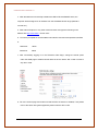
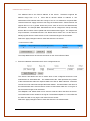
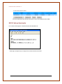
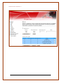
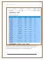
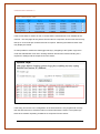
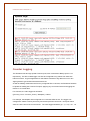
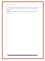
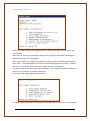
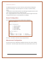
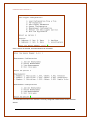
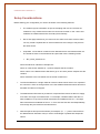
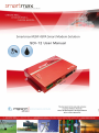
Smartmax SDI 12 Manual 1.3 -1- Smartmax SDI 12 Manual 1.3 TABLE OF CONTENTS CONTACT INFORMATION ....................................................................................................... - 3 RF EXPOSURE AND ELECTRICAL SAFETY COMPLIANCE ................................................. - 4 Caution ...............................................................................................- 4 General Safety ..................................................................................- 5 Vehicle Safety ...................................................................................- 5 Potentially Unsafe Areas ...................................................................- 6 REVISION HISTORY ................................................................................................................ - 7 Introduction ............................................................................................................................. - 8 SDI Features.............................................................................................................................. - 8 SDI-12 Installation..................................................................................................................... - 8 SDI-12 Wiring .......................................................................................................................... - 10 SDI-12 Commands Supported ................................................................................................ - 11 SDI-12 Data Format ................................................................................................................ - 11 SDI-12 Configuration ............................................................................................................. - 13 SDI12 Setup Example: .......................................................................... - 15 Counter Logging .............................................................................. - 19 FTP Client................................................................................................................................ - 22 LogConfig utility ....................................................................................................................... - 24 Sensor Configuration ...................................................................... - 27 Measurement Configuration ............................................................ - 27 Setup Considerations .............................................................................................................. - 29 - -2- Smartmax SDI 12 Manual 1.3 CONTACT INFORMATION In keeping with Maxon's dedicated customer support policy, we encourage you to contact us. TECHNICAL: Hours of Operation: Monday to Friday 8.30am to 5.30pm* Telephone: +61 2 8707 3000 Facsimile: +61 2 8707 3001 Email: [email protected] * Public holidays excluded SALES: Hours of Operation: Monday to Friday 8.30am to 5.30pm* Telephone: +61 2 8707 3000 Facsimile: +61 2 8707 3001 Email: [email protected] WEBSITE: www.maxon.com.au * Public holidays excluded ADDRESS: Maxon Electronics Australia Pty Ltd 36a Gibson Avenue, Padstow Sydney, NSW, Australia 2211 POSTAL ADDRESS Maxon Electronics Australia Pty Ltd Po Box 1, Revesby North, Sydney, NSW Australia 2212 -3- Smartmax SDI 12 Manual 1.3 RF EXPOSURE AND ELECTRICAL SAFETY COMPLIANCE The use of this device in any other type of host configuration may not comply with the RF exposure requirements and should be avoided. During operation, a 20 cm separation distance should be maintained between the antenna, whether extended or retracted, and the user’s/bystander’s body (excluding hands, wrists, feet, and ankles) to ensure RF exposure compliance. The modem is not designed for, nor intended to be, used in applications within 20 cm (8 inches) of the body of the user. Continued compliance of the equipment relies upon it being used with an AS/NZS 60950.1 approved SELV power supply. Caution Change or modification without the express consent of Maxon Electronics Australia Pty. Ltd. voids the user’s authority to use the equipment. These limits are designed to provide reasonable protection against harmful interference in an appropriate installation. The modem is a transmitting device with similar output power to a mobile phone. This equipment generates, uses, and can radiate radio frequency energy and, if not used in accordance with instructions, can cause harmful radiation to radio communication. Use only the supplied or an approved antenna. Unauthorized antennas, modifications, or attachments could impair call quality, damage the device, or result in violation of RF exposure regulations. However, there is no guarantee that interference will not occur in a particular installation. If the equipment does cause harmful interference in radio and television reception, which can be determined by turning the equipment on and off, the user is encouraged to try to correct the interference by one or more of the following measures: Re-orient or relocate the receiving radio or TV antenna Increase the separation distance between the equipment and the receiver Contact Maxon Australia Technical Support for assistance. -4- Smartmax SDI 12 Manual 1.3 General Safety RF Interference Issues: Avoid possible radio frequency (RF) interference by carefully following safety guidelines below: Switch OFF the Modem when in an aircraft. The use of cellular telephones in aircraft is illegal. It may endanger the operation of the aircraft and/or disrupt the cellular network. Failure to observe this instruction may lead to suspension or denial of cellular services to the offender, legal action, or both. Switch OFF the Modem in the vicinity of gasoline or diesel fuel pumps or before filling a vehicle with fuel. Switch OFF the Modem in hospitals and any other place where medical equipment may be in use. Respect restrictions on the use of radio equipment in fuel depots, chemical plants, or in areas of blasting operations. There may be a hazard associated with the operation of your Modem in the vicinity of inadequately protected personal medical devices such as hearing aids and pacemakers. Please consult the manufacturers of the medical device to determine if it is adequately protected. Operation of the Modem in the vicinity of other electronic equipment may cause interference if the equipment is inadequately protected. Observe any warning signs and manufacturers’ recommendations. The modem contains sensitive electronic circuitry. Do not expose the modem to any liquids, high temperatures or shock. The modem is not waterproof. Please keep it dry and store it in a cool, dry place. Only use original accessories or accessories that are authorized by the manufacturer. Using unauthorized accessories may affect your modem’s performance, damage your modem and violate related national regulations. Always handle the modem with care. There are no user serviceable parts inside the modem. Unauthorised dismantling or repair of the modem will void the warranty. Vehicle Safety Do not use the Modem while driving. Respect national regulations on the use of cellular telephones in vehicles. Road safety always comes first. -5- Smartmax SDI 12 Manual 1.3 If incorrectly installed in a vehicle, the operation of the Modem could interfere with the correct functioning of the vehicle’s electronics. To avoid such problems, be sure that the installation has been performed by qualified personnel. Verification of the protection of vehicle electronics should be part of the installation. Note: The user is cautioned that changes or modifications not expressly approved by Maxon Australia could void the warranty. Potentially Unsafe Areas Posted Facilities: Turn off this device in any facility or area when posted notices require you to do so. Blasting Areas: Turn off your device where blasting is in progress. Observe restrictions and follow any regulations or rules. Potentially Explosive Atmospheres: Turn off your device when you are in any area with a potentially explosive atmosphere. Obey all signs and instructions. Sparks in such areas could cause an explosion or fire, resulting in bodily injury or death. Areas with a potentially explosive atmosphere are often but not always clearly marked. They include: fuelling areas such as gas or petrol stations below deck on boats transfer or storage facilities for fuel or chemicals vehicles using liquefied petroleum gas, such as propane or butane areas when the air contains chemicals or particles such as grain, dust or metal powders avoid using the modem in areas that emit electromagnetic waves or enclosed metallic structures e.g. lifts. any other area where you would normally be advised to turn off your engine -6- Smartmax SDI 12 Manual 1.3 REVISION HISTORY Product Model Document Type Current Version Number Status of the Document Revision Date Total Number of Pages Level 1.0 1.2 1.3 1.4 Smartmax SDI-12 MA-2010 FDS 1.3 Public Release July 2013 29 Revision History Date Feb 2012 October 2012 July 2013 July 2014 History Internal/Public Release Version Added Counter logging and Logconfig command line utility Maxon Australia and 12V supply SDI-12 version note -7- Smartmax SDI 12 Manual 1.3 Introduction SDI-12 is a simple ASCII-based protocol and communications standard, used by a multitude of environmental measurement and monitoring equipment types, including rain gauges, water quality sensors and pressure sensors. The Smartmax with SDI-12 functionality is a high performance, self contained, data logger suitable for measuring a number of sensor types. The Smartmax supports SDI-12 V1.3 standard, without support for concurrent measurements. Please note that the 12V sensor supply on the SDI-12 cable is matched to the supply voltage. This means that supply voltage range of the sensor must be matched at the modem supply. SDI Features • Smartmax modem with SDI-12 Interface. • Supports up to 10 SDI-12 sensors with up to 10 measurement types per sensor. • Simple and easy configuration using the Smartmax web interface. • Configurable identification of sensor and measurement type. • SDI-12 data is stored in CSV format. • Configurable sampling rate. • Built in FTP client with scheduler. • Supports storage of up to 30 days of measurement data*. (This data storage is dependant on the number of measurements and sampling rate) SDI-12 Installation 1. Connect the Mini USB cable to the LAN port on the Smartmax. This will require installation of ethernet drivers provided on the CD. 2. Plug the USB cable to a USB port on the computer and power on the SmartMax 3. Windows will prompt you for the LAN drivers; select install the drivers from a specific location and browse the SmartMax CD > Drivers > Ethernet drivers. -8- Smartmax SDI 12 Manual 1.3 4. After Windows has successfully installed the USB to Ethernet/RNDIS driver, the computer will be assigned an IP address from the SmartMax DHCP range (Default is 192.168.0.x) 5. Start Internet Explorer or any other Internet browser and type the following in the Address bar http://192.168.0.1 and hit enter. 6. You will be prompted for the SmartMax web interface username and password, default is: Username: admin Password: admin 7. After successfully logging in to the Smartmax Web Page, change the Mode option under the WAN page to Modem Router Mode as shown below. SDI-12 will not work in any other mode. 8. Go to the license page and make sure that the SDI-12 feature is enabled, if not please refer to the Quick start guide supplied by Maxon with the SDI-12 Kit. -9- Smartmax SDI 12 Manual 1.3 SDI-12 Wiring The SDI-12 cable provided with the kit connects to the serial port on the smartmax. The other end has 3 wires that connect to the sensor. Red - 12V Supply from Modem. Connects to the +12VDC positive supply to the sensor. Black – Common (0V) from Modem. Connects to common line to the sensor. White – SDI-12 Communication - 10 - Smartmax SDI 12 Manual 1.3 SDI-12 Commands Supported Smartmax SDI-12 firmware only supports the “Start Measurement” (aM!) and Additional Measurement (aM1!) commands. SDI-12 Data Format The SDI-12 Data will be saved in CSV format, CSV file will be generated as follow: The .csv file sampler will synchronize the sample period at regular intervals of the Smartmax real time clock. This is achieved by dividing the sample period (in seconds) into linear time from 1st January 1970 00:00. It is recommended that the user chose sample intervals in convenient increments that divide into regular time boundaries. For example, a 20 minute period synchronises with 3 time clock boundaries every hour: xx:00:00, xx:20:00, xx:40:00. A 360 minute (6 hour) period synchronises with 4 real-time clock boundaries every day: 00:00:00, 06:00:00, 12:00:00, 18:00:00. - 11 - Smartmax SDI 12 Manual 1.3 The Smartmax will upload the resulting .csv log files to a configured FTP server as programmed by the user under the SDI-12 settings in the web interface. The Scheduled Upload Time configuration defines the starting time for the first scheduled upload. The Scheduled Upload Interval defines the elapsed time until the next scheduled upload. For example, setting the Scheduled Upload Time to 90 (minutes) and the Scheduled Upload Interval to 12 (hours) would cause the Smartmax to upload files at 1:30am and 1:30pm each day. For periods more than 24 hours the modem uses Sunday as the start reference day. - 12 - Smartmax SDI 12 Manual 1.3 SDi-12 FTP Functionality 1. Sample files will be uploaded to the master station in the order of oldest to newest. After each file has been successfully transferred, the SDI-12 driver in the smarmax firmware will rename the file so as to differentiate the files that have not been transferred yet. 2. The SDI-12 driver in the firmware will replace the "SF" literal from the "SFa_name_zzzzzzzz.csv" file name format (described above) with "Samp". For example, a file sample file named "SF0_ WindDirAve_12345678.csv" would be renamed to "Samp0_ WindDirAve_12345678.csv" after being successfully uploaded. 3. The Smartmax SDI-12 driver will keep .csv log files for 30 days or until 90% of available Flash drive space has been used, after which the oldest files will be deleted as new files are created. The oldest "Samp*.csv" files will be deleted first. All sample files already uploaded will be deleted before any "SF*.csv" files are deleted. 4. When saving new samples, the SDI-12 driver will check for the existence of the relevant .csv file. If it does not exist, a new file will be created. SDI-12 Configuration 1. Once logged on to the Smartmax, proceed to the SmartMax Web page and click on SDI12 tab from the Side menu 2. Enable SDi-12 3. Enter your sensor address, Measurement set, Sample Rate and Sensor Name - 13 - Smartmax SDI 12 Manual 1.3 The 'Address' field is the SDI-12 address of the sensor. address range from 0 to 9. Smartmax supports the Most SDI-12 devices default to address 0. The 'Measurement Set’ Number also has a range of 0 to 9. It is defined for composite SDI12 devices that can supply more than one range of measurements. Sensors that do not support SDI-12 v1.2 or greater should only use a value of zero for the 'Measurement Set’ Number. The ‘Sample Rate’ field allows the user to configure the rate (in minutes) that the SDI-12 sensor will be polled and the measurements logged. The sample rate may be between 1 and 2000 minutes. The 'Name' field is used in the .csv file name to identify log files from the same sensor. It has a maximum length of 25 characters. Select the ‘Apply Changes’ button to save and enter the new sensor. The newly added sensor should now be shown on the Current Sensor Table. 4. Enter the individual measurements for each configured sensor. The ‘Sensor’ field allows the user to select which of the configured sensors the new measurement is associated with. The ‘Measurement No.’ field represents the position of this measurement within the response data to an SDI-12 'Data Collection' command. The sensor’s user manual should provide further details. The Name field is the name of the measurement and is used to label a column of data values within the .csv log file. It has a maximum length of 25 characters. The ‘Multiplier’ and ‘Offset’ fields can be used to scale the value read from the sensor. The scaled value is then written to the log file. The default multiplier is 1.0 and offset 0.0 for users who wish to only log the raw value from the sensor. Select the ‘Apply Changes’ button to save and enter the new measurement. - 14 - Smartmax SDI 12 Manual 1.3 The new measurement should now be shown on the Current Measurement Table. SDI12 Setup Example: For a sensor that supports 4 measurements and had address 0. Web Page example setup for single sensor with 5 Measurement Sets. - 15 - Smartmax SDI 12 Manual 1.3 - 16 - Smartmax SDI 12 Manual 1.3 Once the setup is complete, to verify that the configuration is correct and the SDI12 driver in the smartmax is communicating with the sensor, select the ‘Refresh’ button. After a few seconds, the display should be updated to show the current values read from the sensor. - 17 - Smartmax SDI 12 Manual 1.3 If the Current Value is shown as ‘N/A’, it means that the measurement is not available at the moment. The web page will only wait a few seconds for a response, where some sensors may take up to 10 seconds per measurement set to respond. Selecting the ‘Refresh’ button later may display the results. It’s also possible to monitor the data logger activity by navigating to the System Logs menu under the Administrator menu item. Clicking ‘Refresh’ will show the modem sending out a request for readings and the response from the sensor. If the wiring is incorrect or the configuration in the web interface is not programmed correctly then the SDI12 drivers in smartmax will not communicate with the sensor. The system logs below show modem requesting for data but no response from the sensor. - 18 - Smartmax SDI 12 Manual 1.3 Counter Logging The Smartmax has two high-speed Counter inputs, each connected to Binary inputs 1 & 2 respectively. The SDI-12 data logger can also be configured to log values from these two internal counters. A typical application for this feature would be to log data from one or two "tipping bucket" type rainfall measurement devices. As well as reading measurements from any configured SDI-12 devices, the Smartmax firmware is capable of reading the Counter I/O inputs, applying any conversion factors and logging the results in .csv format files. For Counters, the value logged is as follows: ((Current_Count – Previous_Count) * Multiplier) + Offset For example, the Multiplier was configured as 0.4 and the Offset as 0.0. The logger was configured to read a Counter point every minute and previous count was 1 and it just read a value of 5 at the end of the current minute. The value logged would be ((5 – 1) * 0.4) + 0 = 1.6 - 19 - Smartmax SDI 12 Manual 1.3 The configuration of Counter logging is performed by using Telnet to the modem. Note that the Telnet server needs to be enabled in the modem. This is found on the ‘Administrator/System” web page. Once logged into the Smartmax via Telnet, Counter logging is configured using the ‘logconfig’ utility. See the - 20 - Smartmax SDI 12 Manual 1.3 LogConfig utility section for further details. Configuration of Counter logging is not currently supported on the SDI-12 web page, however the page will display any Counter configurations. - 21 - Smartmax SDI 12 Manual 1.3 In the above example, the Smartmax has been configured with a single Sensor called ‘LocalCounters’ with two measurements consisting of ‘Counter1’ and ‘Counter2’. In this case, both measurements would be logged to the same log file. It is also possible to configure two Counter Sensors, each with one measurement each. In this case, the logger would produce two log files, each with values recorded from each respective Counter input. The Smartmax supports a maximum of two counters. FTP Client FTP Client allows you to upload the log files to a maximum number of 2 destination FTP servers. To use this feature 1. Enable Scheduled FTP Upload 2. Enter the appropriate account credentials 3. Enter the primary and secondary FTP server address, making sure that the username and password is the same for both servers. - 22 - Smartmax SDI 12 Manual 1.3 4. The ‘FTP Directory’ field allows the user to upload the log files to a specified subdirectory on the FTP server. This may be useful in situations where the user wishes to keep the log files from multiple data loggers in separate directories. 5. Change the ‘FTP Port Number’ filed from the default value of 21 if your FTP server is set to a different listener port number. 6. Setup the upload time and interval. Level measurement SDI-12 sensor To configure Level measurement SDI-12 Sensor e.g AD3375MA please make sure to type RS232 on Comms type in the Sensor. - 23 - Smartmax SDI 12 Manual 1.3 - 24 - Smartmax SDI 12 Manual 1.3 LogConfig utility The ‘logconfig’ utility is a simple command line interface into the SDI-12 configuration. The utility is normally run on the Smartmax via a Telnet client. The ‘logconfig’ utility is the only means to configure Counter Input logging, but the utility can also be used to configure SDI-12 sensors and measurements too. Before logging in, check that the Telnet server is enabled in the modem. This is found on the ‘Administrator/System’ web page. Once logged into the Smartmax, enter ‘logconfig <enter>’ at the command prompt. The application main menu is shown below. - 25 - Smartmax SDI 12 Manual 1.3 Enter the number or letter that corresponds with the desired menu item. The menus are not case sensitive. Menu Item ‘R’ causes any configuration changes to be saved to nvram and the data logger is restarted to load the new configuration. Menu item ‘E’ saves any configuration changes to nvram, but does not restart the data logger. Menu Item 1, ‘Load Configuration from a file’ is used for bulk configuration purposes. It loads a text file in .ini format from the Smartmax file system into nvram configuration. Item 2 allows the user to edit the FTP client parameters. The configuration fields are identical to those in the FTP section on the SDI-12 web page. Item 3 edits some global data logger parameters. The ‘Data Logger Enabled’ item corresponds to the ‘Enable SDI-12’ check box on the web page. - 26 - Smartmax SDI 12 Manual 1.3 The ‘Diagnostics Output level’ is a numeric value which controls the amount of diagnostics output from the data logger. This value ranges from 0 (no output), to 5 (maximum debug output). ‘Log Diagnostics to Console’ allows redirection of the data logger’s diagnostics output to a serial consol. It should be normally be left in the default Off (0) state. Item 4, ‘Logging Day Start Time’ is the time of day (0-23 hours) where the logger will close each .csv log file and start a new set. This time defaults to zero (midnight). Sensor Configuration Item 4 from the main menu allows the user to edit the Sensor configuration. Menu item 4, ‘View Sensors’ shows the currently configured Sensors. Measurement Configuration Item 5 from the main menu, ‘Measurement Configuration’ allows the user to edit the individual measurements. First select the parent Sensor Number, whose measurements we wish to edit. - 27 - Smartmax SDI 12 Manual 1.3 Once a sensor is selected, its measurements can be edited. The ‘View Measurements’ item shows the currently configured measurements for the selected Sensor. - 28 - Smartmax SDI 12 Manual 1.3 Setup Considerations Before Starting your configuration you need to be aware of the following features: The modem logs the information as per the sampling rate to a file. The files are created for every measurement under the current sensor table. In this case it has created a file called sentek and a secondary file for Salinity. Due to web page restrictions you cannot use the same name twice as the modem can only create a separate file for each measurement even though it may be from the same sensor. A separate .csv file will be created for each attached sensor and measurement set. The stored file name in the Smartmax file system will use the following format: 1. SFa_name_zzzzzzzz.csv where the literal 'SF' indicates a Sample File… where 'a' is the Sensor Address (0 - 9) whose samples this file contains. .. where 'name' is the Measurement Set Name (up to 25 chars) whose samples this file contains. .. where 'zzzzzzzz' is the 8 character time of the file creation time. The Sensor Address is a single character used to indicate which sensor is to respond to the command. ASCII '0' through ASCII '9' are the standard addresses which all sensors and data recorders must support. The Measurement Set Name is provided for composite SDI-12 devices that can supply more than one range of measurements. For example, a weather station with SDI-12 Device Address 1 may have six Wind measurements available as Set no. 1 and eight Rain measurements available as Set no. 2. Each of these Sets are read independently, even though they are read from the same device. Note that spaces and special characters (for example, $, ?, \, *), will be removed from the 'Measurement Set Name' entry in order to avoid illegal or problematic sample file names. - 29 - Smartmax SDI 12 Manual 1.3 If a Measurement Set Name has not been configured by the user (i.e. empty), the 'name' field in the .csv file name will be replaced with the Measurement Set Number, which is an ASCII '0' through ASCII '9'. The file time / identification field (zzzzzzzz) is an 8 digit hexadecimal value representing the time of file creation. Later sample files for the same Measurement Set will have a higher file identification value. This format enables sample files to be joined in chronological order by sorting sample file-names alpha-numerically. The Smartmax file system has 25 MB of NAND Flash file space available. This should be sufficient to store a max. of 30 days measurements, before being overwritten (should the maximum number of sensors be used). If there are a max. of 10 measurements per range, then each sample would use about 115 characters of file space. At a max. sample rate of 1 minute, this would consume 165,600 bytes/day. Over the allowed 30 day storage period, this would allow 50 points (i.e. 5 Measurement Sets with 10 measurements per range) to sample at a 1 minute rate. The Smartmax SDI-12 driver will open and close the same .csv file each time a new sample set is saved. A new sample file will be opened each calendar day and any files older than 30 days will be deleted at that time. A new file will also be opened if the modem has done a programmed periodic reset. - 30 -