1
Operating manual
InterBus
SK TU1-IBS
SK TU2-IBS
SK TU3-IBS
SK 700E
SK 300/750E
SK 5xxE
BU 0070 GB
GmbH & Co. KG
NORDAC InterBus Operating Manual
Safety and operating instructions
for the drive power inverter
(as per: Low voltage directive 73/23/EEC )
1. General information
4. Installation
During operation, drive power converters may have, depending on
their protection class, live, bare, moving or rotating parts or hot
surfaces.
The installation and cooling of the equipment must be
implemented as per the regulations in the corresponding
documentation.
Unauthorised removal of covers, improper use, incorrect
installation or operation leads to the risk of serious personal injury
or material damage.
The drive power converters must be protected against
impermissible loads. In particular, no components must be bent
and/or the insulation distances changed during transport and
handling. Touching of electronic components and contacts must be
avoided.
Further information can be found in this documentation.
All transportation, installation and initialisation and maintenance
work must be carried out by qualified personnel (compliant with
IEC 364, CENELEC HD 384, DIN VDE 0100, IEC 664 or DIN VDE
0110, and national accident prevention regulations).
For the purposes of these basic safety instructions, qualified
personnel are persons who are familiar with the erection,
installation, commissioning and operation of this product and who
have the relevant qualifications for their work.
2. Intended use
Drive power converters are components intended for installation in
electrical systems or machines.
When being installed in machines, the drive power converter
cannot be commissioned (i.e. implementation of the proper use)
until it has been ensured that the machine meets the provisions of
the EC directive 89/392/EEC (machine directive); EN 60204 must
also be complied with.
Commissioning (i.e. implementation of the proper use) is only
permitted when the EMC directive (89/336/EEC) is complied with.
The drive power converters meet the requirements of the low
voltage directive 73/23/EEC. The harmonised standards in prEN
50178/DIN VDE 0160, together with EN 60439-1/VDE 0660 Part
500 and EN 60146/VDE 0558 were applied for the drive power
converter.
Technical data and information for connection conditions can be
found on the rating plate and in the documentation, and must be
complied with.
3. Transport, storage
Information regarding transport, storage and correct handling must
be complied with.
Climatic conditions in line with prEN 50178 must be complied with.
Drive power converters have electrostatically sensitive
components that can be easily damaged by incorrect handling.
Electrical components must not be mechanically damaged or
destroyed (this may cause a health hazard!).
5. Electrical connection
When working on drive power converters which are connected to
high voltages, the applicable national accident prevention
regulations must be complied with (e.g. VBG 4).
The electrical installation must be implemented as per the
applicable regulations (e.g. cable cross-section, fuses, earth lead
connections). Further instructions can be found in the
documentation.
Information about EMC-compliant installation – such as shielding,
earthing, location of filters and installation of cables – can be found
in the drive power converter documentation. These instructions
must also always be observed for drive converters with CE
approval. Compliance with the limit values specified in the EMC
regulations is the responsibility of the manufacturer of the system
or machine.
6. Operation
Systems where drive power converters are installed must be
equipped, where necessary, with additional monitoring and
protective equipment as per the applicable safety requirements,
e.g. legislation concerning technical equipment, accident
prevention regulations, etc. Modifications to the drive power
converter using the operating software are permitted.
After the drive power converter is disconnected from the power
supply, live equipment components and power connections should
not be touched immediately because of possibly charged
capacitors. Comply with the applicable information signs located
on the drive power converter.
All covers must be kept closed during operation.
7. Maintenance and repairs
The manufacturer documentation must be complied with.
These safety instructions must be kept in a safe place!
Note:
2
This supplementary operating manual is only valid in conjunction with the operating manual
BU 0700/0750 DE / BU 0500 DE / BU 0300 DE supplied for the NORDAC SK 700, SK 750E, SK
5xxE and SK 300E frequency inverters.
Subject to technical alterations
BU 0070 GB
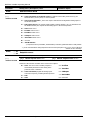
Table of contents
1 INTRODUCTION............................................................................................................................................................... 4
1.1 Instruction notes .................................................................................................................................................. 4
1.2 General information............................................................................................................................................. 4
1.3 Further Information.............................................................................................................................................. 4
1.4 The bus system ................................................................................................................................................... 4
1.5 InterBus in NORDAC frequency inverters........................................................................................................... 5
2 OPTION MODULES FOR SK 300E, SK 5XXE, SK 700E AND SK 750E..................................................................... 6
2.1 Bus modules for the SK 700E and SK 5xxE ....................................................................................................... 6
2.1.1 InterBus module for the SK 700E and SK 5xxE ......................................................................................................... 7
2.1.2 Installation of technology units in the SK 700E .......................................................................................................... 8
2.1.3 Installing the FE (PE) connection ............................................................................................................................... 8
2.2 InterBus module for the SK 300E and SK 750E ................................................................................................. 9
2.2.1 M12 connector assignment ...................................................................................................................................... 10
2.2.2 Installation of technology units in the SK 300E and SK 750E .................................................................................. 11
2.2.3 Installing the FE (PE) connection ............................................................................................................................. 11
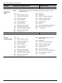
3 BUS CONFIGURATION ................................................................................................................................................. 12
3.1 Laying the bus cables ....................................................................................................................................... 12
3.2 Cable material ................................................................................................................................................... 12
3.3 Cable layout and shielding (EMC measures).................................................................................................... 12
4 THE INTERBUS PROTOCOL ....................................................................................................................................... 13
4.1 Drive profile ....................................................................................................................................................... 13
4.2 Data length ........................................................................................................................................................ 13
4.2.1 PPO type 1 ............................................................................................................................................................... 13
4.2.2 PPO type 2 ............................................................................................................................................................... 13
4.3 Transmission times ........................................................................................................................................... 14
5 FREQUENCY INVERTERS – SETTINGS AND DISPLAYS ........................................................................................ 15
5.1 Frequency inverter bus parameters .................................................................................................................. 15
5.2 Module status .................................................................................................................................................... 20
5.3 LED display ....................................................................................................................................................... 21
6 DATA TRANSMISSION ................................................................................................................................................. 23
6.1 Process data (PZD)........................................................................................................................................... 23
6.1.1 The control word (STW) ........................................................................................................................................... 23
6.1.2 The status word (ZSW) ............................................................................................................................................ 24
6.1.3 The setpoint 1 (SW1) ............................................................................................................................................... 25
6.1.4 Second and third setpoint (SW2/3) .......................................................................................................................... 26
6.1.5 The actual value 1 (IW1) .......................................................................................................................................... 26
6.1.6 Actual value 2 and actual value 3 (IW2/3) ................................................................................................................ 27
6.2 The status machine ........................................................................................................................................... 27
6.3 Parameter orders with Compact PCP ............................................................................................................... 29
6.3.1 Frequency inverter parameters (2000 hex -23E7 hex) ................................................................................................. 29
6.3.2 Drive profile as per DRIVECOM21 ........................................................................................................................... 29
6.4 Drive profile DRIVECOM 21 ............................................................................................................................. 30
6.4.1 Speed functions overview ........................................................................................................................................ 30
6.4.2 Object description .................................................................................................................................................... 31
7 EXAMPLE TELEGRAMS............................................................................................................................................... 32
7.1 Switch-on block → Standby .............................................................................................................................. 32
7.2 Enable with 50% setpoint .................................................................................................................................. 33
7.3 Writing a parameter........................................................................................................................................... 34
8 ADDITIONAL INFORMATION ....................................................................................................................................... 35
8.1 Repairs .............................................................................................................................................................. 35
9 TECHNICAL DATA ........................................................................................................................................................ 36
10 KEYWORD INDEX ....................................................................................................................................................... 37
11 SALES AGENCIES AND BRANCH OFFICES........................................................................................................... 38
BU 0070 GB
3
NORDAC InterBus Operating Manual
1
Introduction
1.1 Instruction notes
The symbol "Attention" refers to actions that could lead to damage to hardware or software or damage to
persons.
Conditions are listed here that you must comply with for correct operation. The symbol "Hand" refers to
tips and advice for efficient use of the device and for reducing additional work.
The symbol "Text" refers to further information sources (manuals, data sheets, etc.). This symbol also
helps you with better orientation in these instructions.
1.2 General information
This InterBus documentation is valid for the device series NORDAC trio SK 300E, SK 5xxE and SK
700/750E.
The respective SK 300E, SK 5xxE and SK 700/750E basic devices are delivered with a dummy cover for the
technology box slot. The basic models do not have any components for parameterisation and control. To be able to
establish communication via the InterBus, an InterBus technology module must be used.
The InterBus interface conforms to the standards DIN 19258 and DIN 19245 Part 2.
1.3 Further Information
These instructions only describe the NORDAC IBS technology module. Further information can be found in the
manuals of Phönix Contact or, with reference to the drive profile, in the DRIVECOM user group.
All the frequency inverter parameters are described in the manuals BU 0300, BU 0500, BU 0700 and BU 0750.
¾
¾
¾
BU 0300, BU 0500, BU 0700, BU 0750 manual
DRIVECOM-Profile No. 21 / 22
IBS PCP compact user manual (Phoenix Contact 10/2002)
Some manuals, instructions, etc. can be located on the Internet:
www.nord.de
www.interbusclub.com
www.phoenixcontact.com
www.drivecom.org
1.4 The bus system
The INTERBUS {xe "INTERBUS field bus system"} open field bus system provides standardised connection of all
process peripherals with all common controllers.
The InterBus is a very efficient bus system which works according to the special master-slave access method, also
referred to as the summation frame protocol. This total frame enables a constant bus cycle.
From a topological viewpoint, InterBus is a ring system, where send and return circuits are sent via every
subscriber. This ensures full duplex operation.
The NORDAC SK 700E and SK 300E can be connected to other sensors/actuators via a serial bus cable. InterBus
differentiates generally between remote bus subscribers (this module) and local bus subscribers that derive as subring systems from the remote bus.
In general, two different data transmission channels are used, the process data channel and the parameter data
channel, and both are supported by this access module.
In each data transmission cycle, a data volume of 3 to 5 words of 16 bit each are transmitted.
4
Subject to technical alterations
BU 0070 GB
1 Introduction
1.5 InterBus in NORDAC frequency inverters
Attributes:
•
Galvanically isolated outgoing bus interface
•
Master-Slave access process; constant bus cycle through total frame protocol
•
Bus length: 400m (between two remote bus subscribers), total length 13km
•
Transfer rate of 500kBit/s (optionally 2Mbit/s)
•
Settable DRIVECOM 21 profile
•
Processing of parameter data via PCP
•
External 24V supply for continuous bus operation without interruptions
•
9-pin Sub-D connector for remote bus connection
•
Max. 256 subscribers (max. 85 NORDAC 700E)
•
Status display with 5 InterBus status LEDs, plus a two-colour operation LED
•
Comprehensive system diagnostics and fast fault localisation
•
Automatic subscriber addressing
BU 0070 GB
Subject to technical alterations
5
NORDAC InterBus Operating Manual
2
Option modules for SK 300E, SK 5xxE, SK 700E and SK 750E
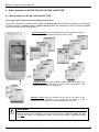
2.1 Bus modules for the SK 700E and SK 5xxE
Technology units, customer units and special extension units
Through the combination of modules for the display, technology units and modules with digital and analog inputs,
as well as interfaces, customer units or special extension units, the NORDAC SK 700E can be easily adapted
to the requirements of various applications.
Technology Units (TU) are modules that can be inserted from above
for display, parameterisation and control of the inverter.
Customer Units (CU) are modules inserted inside the inverter in the
upper recess. They are used for control and communication using
digital/analog signals or bus interfaces.
Extension Units (XU) are inserted into the slot at the base of the
inverter. Such an extension unit is required if the speed is to be
controlled or positioned by an incremental (absolute) encoder.
WARNING
Modules should not be inserted or removed unless the device is free of voltage. The slots
may only be used for the applicable modules. The slots are coded to prevent them being
mixed up.
6
Subject to technical alterations
BU 0070 GB
2 Modules
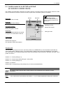
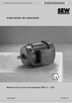
2.1.1 InterBus module for the SK 700E and SK 5xxE
(SK TU1-IBS, Mat. No. 278200065 Æ SK 700E)
(SK TU3-IBS, Mat. No. 275900065 Æ SK 5xxE)
The InterBus communication module SK TU1-IBS is used for connecting drives from the device series SK 700E
and SK TU3-IBS from the device series SK 5xxE to higher-level automation systems via InterBus.
Data width:
Variable (3 words; 5 words)
IBS-IN
IBS-OUT
Baud rate:
Shielding terminal:
Connection to PE of the frequency
inverter to suppress interference in
the Bus lines
500kBit/s (optionally 2Mbit/s)
Shielding terminal
Termination resistor:
Not required;
already integrated in device
External 24V supply
24V
GND
Addressing:
PPO type mode
Implemented automatically via physical
arrangement of subscribers in the bus
Power supply
24V +/-10%
External 24V supply for
bus operation without interruptions.
PPO type mode
The PPO type to be used can be set or the drive profile, as per DRIVECOM 21, can be switched on/off with the
rotary coding switch "PPO type mode". The mode setting is always read in during the initialisation of the whole
bus. If the switch is set to PGM (programming mode), the parameter values from P507 "PPO type" and P551 "Drive
profile" are read in.
Position 1 Æ 3 words (PPO type 1)
Position 2 Æ 3 words with profile (PPO type 1 with profile)
Position 3 Æ 5 words (PPO type 2)
Position 4 Æ Reserve
Position PGM Æ programming mode (settings as per inverter parameterisation)
The settings made using the rotary coding switch are not transferred to the frequency inverter
parameters!
Note:
If the mode switch is permanently set (Position 1 – 3), the software/parameter settings are ineffective!
BU 0070 GB
Subject to technical alterations
7
NORDAC InterBus Operating Manual
SUB-D connector assignment
Incoming remote bus:
DO DI
Forwarding remote bus:
DO DI GND
+5V_OUT
(100mA)
GND
1
6
5
9
1
6
/DO /DI
InterBus status LEDs (see Chap. 5.3):
UL (green):
Supply voltage applied
RC (green):
RemoteCheck:
BA (green):
Bus Active:
RD (yellow):
Remotebus Disabled:
TR (green):
Transmit:
5
9
/DO
/DI
Remote bus to previous InterBus device OK
InterBus data is being exchanged (Bus running)
Remote bus to next InterBus device disabled
Data is being transferred from/to subscribers
Module status 2-colour LED (see Chap. 5.3):
ST (red):
ST (green):
Module error
Module status
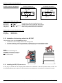
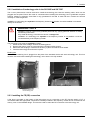
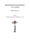
2.1.2 Installation of technology units in the SK 700E
The technology units must be installed as follows:
1. Switch off the mains voltage, observe the waiting period.
2. Remove the dummy cover by actuating the unlocking device on the top and bottom edge.
3. Allow the technology unit to engage audibly by pressing lightly on the installation surface.
NOTE:
Installation of a technology box
separate to the frequency inverter is
not possible. It must be connected
directly to the inverter.
N O RD A C
700E
2.1.3 Installing the FE (PE) connection
A flat plug is provided on the outgoing IBS interface for connection to the FE (function earth) or PE. The
accompanying green-yellow cable must be mounted here and fastened to the housing of the frequency inverter.
8
Subject to technical alterations
BU 0070 GB
2 Modules
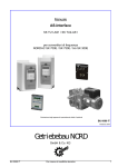
2.2 InterBus module for the SK 300E and SK 750E
(SK TU2-IBS, P. No. 075130080 Æ SK 300E / SK 750E)
The InterBus communication module SK TU2-IBS, is for connecting drives from the trio SK 300E and 750E device
series to higher level automation systems via InterBus.
Bus- In (male)
Bus- Out (female)
InterBus- input
InterBus- output
24V Ext. (male)
External supply
voltage 24V
Data width:
Variable (3 words; 5 words)
Baud rate:
500kBit/s (optionally 2Mbit/s)
Termination resistor:
Not required; already integrated in device
Addressing:
Implemented automatically via physical
arrangement of subscribers in the bus
The status of the InterBus technology unit is shown
by 5(6) LEDs:
• UL (green):
• RC (green):
• BA(green):
• RD(yellow):
• TR(green):
2-colour LED
• ST (green):
• ST (red):
Supply voltage applied
RemoteCheck
Bus Active
Remotebus Disabled
Transmit
Module status
Module error
Æ See Chap. 5.3 "LED display"
Supply:
24V +/-10%
External 24V supply for continuous bus operation without interruptions
BU 0070 GB
Subject to technical alterations
9
NORDAC InterBus Operating Manual
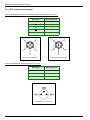
2.2.1 M12 connector assignment
Connector assignment for M12 connector and sockets for Bus In and Bus Out :
2
IBS signal
M12 assignment
DO
1
DO
2
DI
3
DI
4
GND
5
1
1
2
4
4
3
4
3
5
5
Pin (for components)
Socket (for components)
Connector assignment for M8 connector for ext. 24V:
IBS signal
M8 assignment
+24V
1
GND
3
PE
4
Connector (for components)
10
Subject to technical alterations
BU 0070 GB
2 Modules
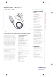
2.2.2 Installation of technology units in the SK 300E and SK 750E
The 6 cover plate screws must be removed to install the technology box. Note the earthing cable, which can be
plugged into the plate. Ensure this cable is connected when installing the technology box to guarantee complete
earthing. Maximum protection class IP66 is only guaranteed if the seal is used and the 6 screws are secured
correctly to create a tight seal.
Installation of a technology box separate to the frequency inverter is not possible. It must be installed or connected
directly on the inverter.
WARNING / NOTE
Installation must be carried out by qualified personnel only, paying particular attention to safety
and warning instructions.
Only install technology units when the device is voltage-free.
Installation of a technology box separate to the frequency inverter is not possible. It must be
connected directly to the frequency inverter.
The technology units must be installed as follows:
1. Switch off the mains voltage, observe the waiting period.
2. Remove the dummy cover by unscrewing the 6 hexagon socket screws.
3. Make sure that the plug-in connections are firmly in place and that the lid is sealed.
4. Insert the technology box and screw in place.
Earthing line
Make sure the earthing line is plugged into the plate of the standard device and each technology unit. This line
must be connected when installing the technology unit to ensure it is fully earthed.
Earthing of the cover plate
Fastening screws for
the technology unit
2.2.3 Installing the FE (PE) connection
A flat plug is provided on the bottom of the technology box for connection to the FE (function earth) or PE. A
connection cable with appropriate components is already included in the frequency inverter and is connected to the
dummy cover in the standard design. This must be used to create the PE connection to the technology unit.
BU 0070 GB
Subject to technical alterations
11
NORDAC InterBus Operating Manual
3
Bus configuration
An InterBus network consists of a maximum of 256 subscribers and is based on a ring topology. The number of
subscribers is dependent on the number of IO's. With a useful data length of 3 words, it is possible to connect 85
devices with the NORDAC 700E.
3.1 Laying the bus cables
In an industrial environment the correct installation of the Bus system is particularly important in order to reduce
potential interference. The following points are designed to help prevent interference and problems right from the
start. The installation guidelines are not complete as applicable safety and accident prevention guidelines must
also be complied with.
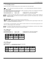
3.2 Cable material
The guaranteed transfer speeds or transfer distances can only be achieved without errors if the specific cable
parameters are complied with.
Max. line
capacitance
Resistance
Cable cross-section
Baud rate
60nF/km
250mΩ/m
3*2*0.2 mm2
500k
See also http://www.interbusclub.com/de/doku/pdf/kabel-d.pdf
Certified InterBus data cables are recommended.
Designation (example):
INTERBUS
Certified! No. xxx
3.3 Cable layout and shielding (EMC measures)
If EMC measures are not in place, high-frequency interference which is principally brought about by switch
procedures or lightning often causes electronic components in the bus subscribers to be faulty and error-free
operation can no longer be ensured.
Appropriate shielding of the bus cable reduces electrical interference which can arise in an industrial environment.
You can achieve the best shielding qualities with the following measures
•
Connect the bus subscribers with the shortest amount of cable possible.
•
The shielding on the bus line must be applied completely on both sides.
•
Avoid using tap lines to connect field devices to the bus.
•
Avoid extending the bus lines using plug connectors.
Bus lines should be laid with a minimum spacing of 20 cm to other lines which carry a voltage higher than 60V.
This applies to lines laid inside and outside of control cabinets.
If earthing potential values are different, transient current may flow through shielding which is connected on
both sides. This may be a danger to electronic components. Differences in potential must be reduced using
sufficient potential equalisation.
12
Subject to technical alterations
BU 0070 GB
4 The InterBus protocol
4
The InterBus protocol
InterBus works with a summation frame protocol. Each subscriber has a fixed data length.
Note:
If the mode switch is permanently set (Position 1 – 3), the software/parameter settings are ineffective!
4.1 Drive profile
If the drive is to be operated as per DRIVECOM 21 profile, the frequency inverter can be configured via Parameter
551. This also changes the ID of the subscriber.
Drive profile On (P551 = 1)
ID[7..0]= E3h
Æ DRIVECOM with 1 PCP word, RemoteBus
Drive profile Off (P551 = 0)
ID[7..0]= F3h
Æ Module with 1 PCP word, RemoteBus
To render the profile change effective, the module must be reinstalled (e.g. switch the mains voltage off
and then on again). The entire bus must also be restarted. The profile is only effective with 3 word data
lengths (PPO type 1).
4.2 Data length
The default setting is 5 words when the inverter is switched off.
Attention: After the frequency inverter is switched on, the profile and PPO type settings are read in and
the InterBus reinitialised (P507 and P551).
The data length can be set between 3 and 5 words for the IBS module and is set via the PPO types (P507: see
Chap. 5.1). The PPO types 3 and 4 are reserved.
To render the data length change effective, the InterBus must be reinstalled (e.g. switch the mains voltage
off and then on again). The entire bus must also be restarted.
4.2.1 PPO type 1
3 words data width
Drive profile On (P551 = 1)
Drive profile Off (P551 = 0)
Byte
0
1
Æ DRIVECOM with 1 PCP word, RemoteBus
Æ Module with 1 PCP word, RemoteBus
ID[7..0]= E3h
ID[7..0]= F3h
2
3
4
5
out
PCP
Control word
Speed setpoint
(rpm)
in
PCP
Status word
Speed actual
value (rpm)
4.2.2 PPO type 2
5 words data width
ID[7..0]= F3h
Æ Module with 1 PCP word, RemoteBus
Note: The parameter "Drive profile" has no effect.
Byte
0
1
2
3
4
5
6
7
8
9
out
PCP
Control word
Setpoint 1
Setpoint 3
Setpoint 2
in
PCP
Status word
Act. value 1
Act. value 3
Act. value 2
BU 0070 GB
Subject to technical alterations
13
NORDAC InterBus Operating Manual
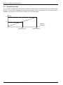
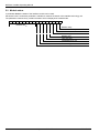
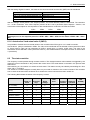
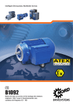
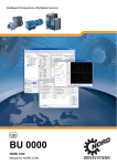
4.3 Transmission times
The cycle time is dependent on the number of words to be transmitted. It increases linearly with increasing word
quantity. The cycle time in dependence on the total word length is shown in the diagram for a transmission rate of
500kBit/s. The number of inverters shown is based on a 3 word data length.
t /[ms]
14
7,2
Words in
total frame
1
14
128
(equiv. to 42 FI)
256
(equiv. to 85 FI)
Subject to technical alterations
BU 0070 GB
5 Settings and displays
5
Frequency inverters – settings and displays
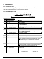
5.1 Frequency inverter bus parameters
To operate the inverter with the InterBus protocol, the bus must be connected to the master and some settings
have to be made on the frequency inverter.
With InterBus protocol, the inverter parameters are mapped in the range 2000hex to 23E7hex (= 8192dec to
9191dec), i.e. when parameterisation is carried out via the bus, the parameter numbers must be added to the
value 2000hex (e.g. P508 → obj 21FChex).
The frequency inverter can always be parameterised. Control of the inverter via InterBus can be activated by
setting parameter P509 to value 12, 13 or 14. (see below)
Available in Option
Parameter
Setting value / Description / Note
P507
PPO type
1 ... 4
Only with Profibus or InterBus option
[1]
1
= PPO type 1: InterBus with data length of 3 words (see Chap. 4.2.1)
2
= PPO type 2: InterBus with data length of 5 words (see Chap. 4.2.2)
Always visible
3, 4 = PPO type 3, 4: reserved
P509
Interface
0 ... 21
Selection of the interface from which the inverter is controlled.
[0]
0 = Control terminals or keypad control with the Control Box (optional), the ParameterBox
(optional) or the potentiometer option.
valid for
SK 300/700/750E
1 = Control terminals only. The inverter can only be controlled via the digital inputs and the analog
input.
Always visible
12= InterBus setpoint. The frequency setpoint is transferred via InterBus. Control via the digital inputs
is still active.
13= InterBus control word. The control signals (enable, rotational direction ...) are transferred via
InterBus, the setpoint via the analog input or the fixed frequencies.
14= InterBus. All control data and setpoints are transferred via InterBus. The analog input and the
digital inputs have no function (except safety functions, see below)
P510
Auxiliary setpoint interface
0 ... 7
Selection of the interface from which the inverter is controlled.
[0]
0 = Auto: The auxiliary setpoint value is automatically 3 =
taken from the interface of the master setpoint value 4 =
P509 >interface<
5=
1 = USS
6=
2 = CANbus
7=
valid for
SK 300/700/750E
BU 0070 GB
Subject to technical alterations
Always visible
Profibus
InterBus
CANopen
DeviceNet
Reserved
15
NORDAC InterBus Operating Manual
Parameter
Available in Option
Setting value / Description / Note
P509
Source control word
Selection of the interface via which the FI is controlled.
0 ... 9
[0]
valid for SK 5xxE
0 = Control terminals or keyboard control ** with the Control Box (when P510=0), the
Parameter Box (not ext. p-box) or via Bus I/O Bits.
1 = Only control terminals *, the FI can only be controlled via the digital and analog inputs or
via the Bus I/O Bits.
2 = USS control word *, the control signals (enable, rotation direction, etc.) are transferred via
the RS485 interface, the setpoint via the analog input or the fixed frequencies.
3 = CAN control word *
4 = Profibus control word *
5 = InterBus control word *
6 = CANopen control word *
7 = DeviceNet control word *
8 = reserved
9 = CAN Broadcast *
*) Keyboard control (ControlBox, ParameterBox) is blocked, parameterisation is still possible.
**) If the communication during keyboard control is interrupted (time out 0.5 sec), the FI will block
without an error message.
P510
... - 01
... - 02
0 ... 8
[0]
Setpoint source
Selection of the setpoint source to be parameterised.
[01] =
Master setpoint value source
[02] = Master setpoint value source
valid for SK 5xxE
Selection of the interface via which the FI receives the setpoint.
0 = Auto: The source of the auxiliary setpoint is
automatically derived from the setting in the
parameter P509 >Interface<
1 = Control terminals, digital and analog inputs
control the frequency, including fixed frequencies
2 = USS
5 = InterBus
6 = CANopen
7 = DeviceNet
8 = reserved
3 = CAN
16
4 = Profibus
Subject to technical alterations
BU 0070 GB
5 Settings and displays
Parameter
Available in Option
Setting value / Description / Note
P513
Telegram down time
0.0 / 0.1 ... 100.0 s
Monitoring function of the active bus interface. Following receipt of a valid telegram, the next one must
arrive within the set period. Otherwise the inverter reports an error and switches off with the error
message E010 >Bus Time Out<.
[ 0.0 ]
Always visible
Monitoring is switched off at a setting value of 0.0.
P543 (P)
Actual bus value 1
0 ... 21
The return value 1 (IW1) can be set for bus control in this parameter.
[1]
0=
1=
2=
3=
4=
5=
6=
7=
8=
9=
P544 (P)
Actual bus value 2
0 ... 21
The return value 2 (IW2) can be set for bus control in this parameter.
[0]
This parameter is identical to P543.
Always visible
Off
Actual frequency
Actual speed
Current
Torque current
Status of digital inputs and relay
Actual position (with PosiCon, SK 700E only)
Setpoint position (with PosiCon, SK 700E only)
Setpoint frequency
Error number
10 = Actual position increment1 (with PosiCon, SK
700E only)
11 = Actual position increment1 (with PosiCon, SK
700/750E only)
12 = Bus IO Out Bits 0...7
13 = ... 16 (reserved)
17 = Value analog input 1 (P400)
18 = Value analog input 2 (P405)
19 = Setpoint frequency master value (P507)
20 = Setpoint frequency after master value ramp
21 = Setpoint frequency without master value slip
Always visible
Condition is PPO 2 or PPO 4 type (P507).
P545 (P)
Actual bus value 3
0 ... 21
The return value 3 (IW3) can be set for bus control in this parameter. This is only available if P546 is ≠
3 (not with SK 5xxE).
[0]
Always visible
This parameter is identical to P543.
Condition is PPO 2 or PPO 4 type (P507).
P546 (P)
Bus setpoint 1
0 ... 6
In this parameter, a function is assigned to the delivered setpoint 1 (SW1) for bus control.
[1]
0=
1=
2=
3=
4=
5=
6=
valid for
SK 300/700/750E
Always visible
Off
Setpoint frequency (16 Bit)
16-bit setpoint position (with PosiCon option only)
32-bit setpoint position (only available with PosiCon option and when PPO type 2 or 4 is selected)
PosiCon control terminals (only available with PosiCon option, 16-bit)
Setpoint position (16 Bit) increment1 (with PosiCon, SK 700E only)
Setpoint position (32 Bit) increment1 (with PosiCon, SK 700E only)
1
BU 0070 GB
The setpoint/actual position corresponding to an 8192 increment encoder.
Subject to technical alterations
17
NORDAC InterBus Operating Manual
Available in Option
Parameter
Setting value / Description / Note
P546
Function bus - Setpoint 1
0 ... 24
In this parameter, a function is allocated to the output setpoint 1 during bus actuation.
[1]
NOTE:
valid for SK
5xxE
Always visible
Further details can be found in the respective BUS operating instructions or in the
description of P400.
0 = Off
12 = Reserved
1 = Setpoint frequency (16 Bit)
13 = Multiplication
2 = Torque current limit (P112)
14 = PI process controller actual value
3 = Actual frequency PID
15 = PI process controller setpoint
4 = Frequency addition
16 = PI process controller lead
5 = Frequency subtraction
17 = Digital In Bits 0...7
6 = Current limit (P536)
18 = Reserved
7 = Maximum frequency (P105)
19 = Status output (P434/441/450/455=38)
8 = Actual PID frequency limited
20 = Value analog output (P418=31)
9 = Actual PID frequency monitored
21 = … 24 reserved
10 = Torque servo mode (P300)
11 = Torque lead (P214)
P547 (P)
Bus setpoint 2
0 ... 20
In this parameter, a function is assigned to the delivered setpoint 2 (SW2) for bus control.
Always visible
[0]
valid for
SK 300/700/750E
0 = Off
1 = Setpoint frequency (16 Bit)
2 = Torque current limit (P112)
3 = Actual frequency PID
4 = Frequency addition
5 = Frequency subtraction
6 = Current limit (P536)
7 = Maximum frequency (P105)
8 = Actual PID frequency limited
9 = Actual PID frequency monitored
10 = Torque servo mode (P300)
12 = Control terminals PosiCon (only with
PosiCon option)
13 = Multiplication
14 = PI process controller actual value
15 = PI process controller setpoint
16 = PI process controller lead
17 = Digital In Bits 0...7
18 = Curve travel calculator
19 = Status output (P434/441/450/455=38)
20 = Value analog output (P418=31)
21 = … 24 reserved
11 = Torque lead (P214)
18
Subject to technical alterations
BU 0070 GB
5 Settings and displays
Parameter
Available in Option
Setting value / Description / Note
P547
Function bus - Setpoint 2
Always visible
0 ... 24
[0]
valid for SK
5xxE
P548 (P)
0 ... 20
This parameter is identical to P546.
Bus setpoint 3
Always visible
In this parameter, a function is assigned to the delivered setpoint 3 (SW3) for bus control. Only
available if P546 is ≠ 3.
[0]
valid for
SK 300/700/750E
P548
This parameter is identical to P547.
Function bus - Setpoint 3
Always visible
0 ... 24
[0]
This parameter is identical to P546.
valid for SK
5xxE
P551
Drive profile
On / Off
The InterBus Drivecom profile is activated with this parameter.
[ 0 = Off ]
0: Switch off profile
Always visible
1: Switch on profile as per DRIVECOM 21
Information parameters:
P745
Module version
0 ... 32767
Software version of the installed module
(InterBus technology unit Index 01)
P746
Module status
0000 ... FFFF hex
Status of installed modules (see 5.2)
Always visible
Array level:
[01] Technology unit
[02] Customer unit
[03] Special extension unit
Always visible
Array level:
(InterBus technology unit Index 01)
[01] Technology unit
[02] Customer unit
[03] Special extension unit
NOTE
When activated, the functions block voltage, quick stop, remote control and error
acknowledgement are available at the control terminals (local). To operate the drive, a high
signal must be present on the digital inputs being used before the drive can be enabled.
BU 0070 GB
Subject to technical alterations
19
NORDAC InterBus Operating Manual
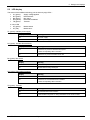
5.2 Module status
In parameter P746, the status of the InterBus module can be read.
Parameter P746 is a subindex parameter: Subindex 0 contains the status of the InterBus technology unit.
The parameter contains binary coded information which is displayed in hexadecimals:
15 14 13 12 11 10
Module - ID
InterBus=0Dhex
9
8
7
6
5
4
3
2
1
0
Module ready
Module in status “operational”
Initialisation active
Reserved (0)
Module error
Time-out error
Initialisation error (0)
Reserved (0)
20
Subject to technical alterations
BU 0070 GB
5 Settings and displays
5.3 LED display
The status of the InterBus technology unit is shown by 5(6) LED's :
• UL (green):
Supply voltage applied
• RC (green):
RemoteCheck
• BA (green):
Bus Active
• RD (yellow):
Remotebus Disabled
• TR (green):
Transmit
2-colour LED
• ST (green):
• ST (red):
Module status
Module error
UL (green): InterBus power supply
Display
Meaning
Off
No power supply
On
InterBus power supply OK
RC (green): InterBus RemoteCheck
Display
Meaning
Off
Remote bus to previous subscriber interrupted
- check corresponding cable connection
On
Remote bus to previous InterBus device OK
BA (green): Bus Active
Display
Meaning
Off
InterBus in stop state
On
InterBus data is being exchanged
RD (yellow): RemoteBus Disabled
Display
Meaning
Off
Remote bus to next InterBus device OK
On
Remote bus to next InterBus device disabled
- check corresponding cable connection
TR (green): Transmit
BU 0070 GB
Display
Meaning
Off
No communication at the moment
On
Communication telegrams are being transmitted to the access module
Subject to technical alterations
21
NORDAC InterBus Operating Manual
ST (red/green): Module status / Module error
ST (green) module status:
Display
Meaning
Off (red/green)
No voltage supply
Flashing (alternating with red)
Initialisation (init. phase)
On
Module OK
Display
Meaning
On
System error
Rapid flashing (0.2s)
Initialisation phase
Slow flashing (0.5s)
Time-out error
Isolated flashing
Inverter error (see frequency inverter instructions)
On
System error, e.g. plug contact not correct
ST (red):
22
Subject to technical alterations
BU 0070 GB
6 Data transmission
6
Data transmission
6.1 Process data (PZD)
The inverter with InterBus technology unit is a slave on the InterBus. The process date are setpoint and actual data
that need to be transmitted rapidly, e.g. motor speed.
In the process data area (PZD), control words and setpoints are transferred from the master to the slave and in
return, status words and actual values are sent from the slave to the master.
6.1.1 The control word (STW)
The control word (STW) is the first word transferred to the frequency inverter in the process data area in an order
telegram.
PZD1
PZD2
PZD3
PZD3
STW
SW1
SW3
SW2
15 14 13 12 11 10
9
8
7
6
5
4
3
2
1
0
Significance of the individual bits
Bit
0
Value Significance
1
0
1
0
OFF 1
ON
OFF 2
2
1
0
Operating condition
OFF 3
3
1
0
Operating condition
Block operation
4
1
0
Enable operation
Block run-up encoder
1
0
1
0
1
0
1
Operating condition
Stop run-up encoder
Enable run-up encoder
Block setpoint
Enable setpoint
5
6
7
8
9
10
0/1
0/1
0
1
11
0
1
0
1
0/1
0/1
0/1
12
13
14
15
BU 0070 GB
Acknowledge
PZD invalid
PZD valid
Rotation right
Comments
Return with the brake ramp, at f=0Hz voltage activation
Ready for operation
Block voltage; the inverter output voltage is switched off, the FI goes
into switch-on block status.
OFF 2 is cancelled
Emergency stop with programmed emergency stop time; at f = 0Hz
voltage enable; the FI goes into switch-on block status
OFF 3 is cancelled
Block voltage; the inverter output voltage is switched off, the FI goes
into standby status.
Output voltage enabled, run-up to present setpoint.
Run-up encoder is set to zero; at f = 0Hz no voltage enable; FI
remains in operation enabled status.
Run-up encoder is enabled
Freezing of actual setpoint from run-up encoder (hold frequency).
Enable setpoint on run-up encoder
Selected setpoint is set to zero in the run-up encoder.
Selected setpoint on run-up encoder is activated.
With the switch from 0 to 1, inactive errors are acknowledged.
Note: If a digital input is programmed to function "Error ack.", this Bit
must not be set permanently to 1 via the bus (this will otherwise
prevent edge detection).
Reserved
Reserved
The transmitted process data is invalid.
Valid process data is transferred from the master.
Note: If setpoints only are transferred via the bus (setting: interface),
this Bit must be set so that the setpoint transferred is valid.
Rotation right is on
Rotation left
Rotation left is on
Reserved
Parameter set switch Bit 0
00 Parameter set 1
10 Parameter set 3
Par. set switch Bit 1
Subject to technical alterations
01 Parameter set 2
11 Parameter set 4
23
NORDAC InterBus Operating Manual
6.1.2 The status word (ZSW)
The status word (ZSW) is the first word transferred to the inverter in the process data area in the inverter response
telegram.
PZD1
ZSW
PZD2
IW1
15 14 13 12 11 10
9
PZD3
IW3
8
7
6
PZD3
IW2
5
4
3
2
1
0
Significance of the individual bits
Bit
0
1
2
3
4
5
6
7
8
Value Significance
0
1
0
Not on standby
Standby
Not operational
1
Ready for operation
0
1
0
1
Operation blocked
Operation enabled
No errors
Error
0
1
0
1
0
1
0
1
0
OFF 2
No OFF 2
OFF 3
No OFF 3
No switch-on block
Switch-on block
No warning
Warning
Actual value not O.K.
1
9
10
0
1
0
1
11
12
13
0
1
0
1
0
1
24
14
0/1
15
0/1
Comments
Initialisation complete, load relay on, output voltage blocked
Causes: No On command, an error has occurred, OFF 2 or OFF 3
active, switch-on block status active.
On command active, no errors. The inverter can be started with the
ENABLE OPERATION command.
Output voltage enabled, run-up to present setpoint.
Drive malfunctioning therefore out of order, if acknowledgement is
successful, will go to switch-on block status.
OFF 2 command active
OFF 3 command active
Goes through OUT 1 to Standby status
Drive still in operation, no acknowledgement necessary
Actual value does not match the setpoint (with posicon: Setpoint
position not reached)
Actual value O.K.
Actual value matches the setpoint (setpoint reached)
(with posicon: Setpoint position reached)
Local guidance
Local guidance active on device
Guidance required
The Master is called upon to take over the guidance.
MFR 1 reference value Programmed function of the MFR 1 not met or
undershot
actual value < programmed reference value
MFR 1 reference value Programmed function of the MFR 1 met or
reached
actual value > programmed reference value
Rotation right
Inverter output voltage has right-hand rotating field
Rotation left
Inverter output voltage has left-hand rotating field
MFR 4 reference value For SK 700E only with posicon upgrade: status MFR 4 = 0
undershot
MFR 4 reference value For SK 700E only with posicon upgrade: status MFR 4 = 1
reached
Actual active parameter
00 Parameter set 1
set Bit 0
01 Parameter set 2
Actual active parameter
set Bit 1
10 Parameter set 3
11 Parameter set 4
Subject to technical alterations
BU 0070 GB
6 Data transmission
6.1.3 The setpoint 1 (SW1)
The function of the 1st setpoint is set in parameter P546. The following options are available:
Setpoint frequency (16 Bit)
The setpoint frequency in setpoint 1 is transferred as a 16 Bit value as standard. Setpoint 1 is transferred to the
inverter as the second word in the process data area in the order telegram.
PZD1
STW
15 14 13 12 11 10
PZD2
SW1
9
PZD3
SW3
8
7
6
PZD3
SW2
5
4
3
2
1
0
The setpoint is transferred as a whole number with a value range of -32768 to 32767 (8000 hex to 7FFF hex). The
value 16384 (4000 hex) is equal to 100%. The value C000 HEX is equal to -100%. A setpoint of 100% corresponds
to the parameter maximum frequency (parameter P105) set in the same parameter set.
Setpoint position (16 or 32 Bit)
Using the posicon special upgrade for the SK 700E, the absolute setpoint position can be transferred in setpoint 1.
It can be transferred as a 16 or 32 Bit value with a resolution of 1=0.001 revolutions. In addition, the control
terminals (PosiCon control bits setting) can be transferred in binary.
16-Bit setpoint position setting:
A value range of +32767 (= 32.767 revolutions) to -32768 (= -32.768 revolutions) is possible as a 16 Bit value. The
16 Bit setpoint position is transferred as a second word in the area of the process data (like the setpoint frequency,
see above)
32-Bit setpoint position setting:
The full position range of +/- 50000,000 revolutions is available as a 32 Bit value. The 32 Bit setpoint position is
transferred as the second and third word in the process data area:
PZD1
STW
PZD2
PZD3
SW1
PZD3
SW2
Posicon control bits setting:
A 16 Bit value is transferred in which the control terminals of the posicon special extension unit are mapped. The
setpoint position is based on the position array / position increment as per the P610 setpoint mode.
The transferred bits have the following significance (see operating instructions BU 0710):
Bit 0 -5
Bit 6
Bit 7
Bit 8
Bit 9
Bit 10
BU 0070 GB
Bit0-Bit5 positional array / positional increm.
Reference point run
Reference Point
Teach-in
Quit teach-in
Reset position
Subject to technical alterations
25
NORDAC InterBus Operating Manual
6.1.4 Second and third setpoint (SW2/3)
If the PPO type 2 or 4 is used, in addition to setpoint 1, a 2nd setpoint can be transferred in word PZD4 and a 3rd
setpoint in PZD3.
PZD1
STW
PZD2
SW1
PZD3
SW3
PZD3
SW2
A third setpoint value can only be transferred if a 32 Bit setpoint value is not transferred in the first setpoint.
PZD1
PZD2
PZD3
PZD3
STW
SW1
SW2
The second and third setpoints are always 16 Bits. The function of the second and third setpoints can be set in the
inverter with parameter P547 ‘Setpoint 2 function’ and P548 ‘Setpoint 3 function’ respectively.
Both setpoints are transferred as whole numbers in the range -32768 to 32767. The value 16384 (4000 HEX) is
equal to 100%. The value C000 HEX is equal to –100%, so setpoints in the range –200% to +200% can be
transferred. A setpoint of 100% corresponds to the respective nominal size:
Setting
Off
Setpoint frequency, actual frequency PID, actual
frequency PID limited, actual frequency PID
monitored, frequency addition, frequency
subtraction, maximum frequency
Torque current limit
Current limit
Servo mode torque
Torque precontrol
100% equals
Maximum frequency
Torque current limit (P112)
Inverter nominal current
Nominal torque
Torque precontrol (P214)
In addition, PosiCon control bits can be transferred here (see setpoint 1)
6.1.5 The actual value 1 (IW1)
The actual frequency , i.e. the actual output frequency of the inverter, is transferred as a 16 Bit value as standard.
The actual value 1 is transferred to the master in the inverter response telegram as the second word in the process
data area.
PZD1
ZSW
15 14 13 12 11 10
PZD2
IW1
9
PZD3
IW3
8
7
6
PZD3
IW2
5
4
3
2
1
0
The actual value 1 is transferred as a whole number in the range -32768 to 32767. In addition to the actual
frequency, other actual inverter values can be transferred. The setting is made in P543 'Actual value 1 function'.
The settings ‘Actual frequency’, ‘Actual speed’, ‘Current’ and ‘Torque current’ are transferred as percentages of the
respective nominal sizes. The value 16384 (4000 HEX) is equal to 100%. The value C000 HEX is equal to -100%.
Actual values in the range –200% to +200% can be transferred.
26
Subject to technical alterations
BU 0070 GB
6 Data transmission
With the setting ‘Digital I/O status’, the states of the control terminals and the relay (MFR) can be transferred:
Bit
Bit 0 -5
Bit 6-11 for Posicon special extension unit
Bit 6 for encoder special extension unit
Bit 12 -15
Status
Digital input 1-6
Digital input 7-12
Digital input 7
Multifunctional relay 1-4
With the settings ‘Actual position’ and ‘Setpoint position’, the actual absolute position is transferred. The resolution
is 1 = 0.001 revolutions. If the value ‘Setpoint position 32 Bit’ is set in parameter P546 ‘Setpoint 1 function’, the
actual value of the setpoint or actual position is also transferred as a 32 Bit value in PZD2 and PZD3:
PZD1
ZSW
PZD2
PZD3
PZD3
IW2
IW1
Please notice: with all SK5XXE inverter units the SW2 and SW3 are exchanged and IW2 and IW3 are
exchanged, too. So the setpoints protocol is STW – SW1 – SW2 – SW3 and the status is ZSW – IW1 – IW2 –
IW3.
6.1.6 Actual value 2 and actual value 3 (IW2/3)
It is possible to forward two more actual values to the controller when PPO type 2 or 4 is used for transfer.
Actual value 2 (IW2) is transferred in PZD4. The value to be transferred can be selected in P544 (actual bus value
2). Actual value 3 (IW3) can be transmitted in PDZ3 if actual value 1 is not a 32 Bit value. The value to be
transferred can be selected in P545 (actual bus value 3). The standardisations correspond to those of actual value
1 (see above)
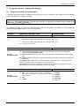
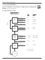
6.2 The status machine
The frequency inverter passes through a status machine. The changes between various states are triggered by the
respective control commands in the process data control word. The actual status is returned in the process data
status word.
After switching on, the inverter is in switch-on block status. This status can only be ended by transmitting the “Shut
down (Off 1)” command.
The answer to a master telegram normally does not yet contain a reaction to the control command. The controller
has to check the answers from the slaves as to whether the control command has been carried out.
The following Bits indicate the status of the frequency inverter:
Status
Bit6
Bit5
Bit 4
Bit2
Bit1
Switch-on
block
Emergency
stop
Block
voltage
Error
Operation
enabled
Ready for
operation
Standby
Not on standby
0
X
X
0
0
0
0
Switch-on block
1
X
X
0
0
0
0
Standby
0
1
1
0
0
0
1
activated
0
1
1
0
0
1
1
Operation enabled
0
1
1
0
1
1
1
Error
0
X
X
1
0
0
0
Error active
0
X
X
1
1
1
1
Emergency stop active
0
0
1
0
1
1
1
BU 0070 GB
Bit3
Subject to technical alterations
Bit0
27
NORDAC InterBus Operating Manual
5
Internal status machine
Sw itching on the inverter
Bit2 = 0: Emergency stop
1
Not on standby
3
4
5
6
6
8
Bit1 = 0: Block voltage
v Bit2 = 0: Emergency stop
Loading relay applied
Emergency
stop active
2
f = 0 reached
(Emergency stop ended)
2
4
Sw itch-on block
5
From every device status
Bit0 = 0: Shut dow n
& Bit1 = 1: Enable voltage
& Bit2 = 1: Enable pulses
(xxxx x1xx xxxx x110)
Bit0 = 0: Shut dow n
Error
3
2
5
7
Error reaction
active
Standby
5
Bit 3 = 0: Block operation
Error reaction
ended
Bit0 = 1: Sw itch on
4
2
3
8
activated
3
Bit3 = 1: Enable operation
& Bit0 = 1: Sw itch on
Error
2
Bit3 = 1: Enable operation
5
2
3
4
6
Operation
enabled
Bit7 0Î 1
error acknow ledgement
Bit4 = 0: Move dow n emergency ramp and
remain in "Operation enabled"
Bit5 = 0: Hold frequency
Bit6 = 0: Setpoint = 0%
Control bits
0. Ready for operation / shut dow n
1. Block / enable voltage
2. Enable pulses / emergency stop
3. Block / enable operation
4. Operation condition / block RUE
5. Enable / stop RUE
6. Block / enable setpoint
7. Error acknow ledgement (0Î 1)
10. Control data valid / invalid
11. Rotation right
12. Rotation left
14. Parameter set Bit 0
15. Parameter set Bit 1
28
Priority of control com mands:
1. Block voltage
2. Emergency stop
3. Shut dow n
4. Enable operation
5. Sw itch on
6. Block operation
7. Reset error
Subject to technical alterations
Designation of states:
1: Bit 0 = 0
2: Bit 6 = 1
3: Bit 0 = 1
4: Bit 1 = 1
5: Bit 2 = 1
6: Bit 5 = 0
7: Bit 2 & Bit 3 = 1
8: Bit 3 = 1
BU 0070 GB
6 Data transmission
6.3 Parameter orders with Compact PCP
Parameter data are divided into individual parameter blocks and transmitted in sequence. This is implemented by
the PCP (Peripherals Communication Protocol). The transmission of a parameter can therefore take several bus
cycles. This is slower in comparison to process data transmission.
The IBS technology unit has an integrated 1 word PCP channel.
The PCP is implemented in the Compact PCP version.
Compact PCP has limited functionalities in comparison to the full PCP version. The following commands are
supported: initiate, read, write
The Phoenix Contact software for the InterBus master offers full Compact PCP support from firmware
4.60 onwards.
The object index (OI) used in PCP is omitted here.
6.3.1 Frequency inverter parameters (2000 hex -23E7 hex)
All FI parameters can be accessed directly via the parameter channel.
With InterBus protocol, the inverter parameters are mapped in the range 2000hex to 23E7hex (= 8192dec to
9191dec), i.e. when parameterisation is carried out via the bus, the parameter numbers must be added to
the value 2000hex (e.g. P508 → obj 21FChex).
Index
200023E7
Sub
-
Object
Manufacturer-specific
parameters
Description
FI parameters
(see inverter operating instructions)
Unit
-
Acc Type
-
-
6.3.2 Drive profile as per DRIVECOM21
The following parameters are only valid if the frequency inverter parameter drive profile (P551) is
switched on. The profile is not valid in PPO type 2.
The objects remain valid for the 1st parameter set only.
The DRIVECOM objects are described in more detail in Chap. 6.4.
Index
6000
6001
6002*
603F
6040*
6041*
6042
6043
6044
6046
6048
6049
Sub
ARR
1
2
REC
1
2
REC
1
2
•
BU 0070 GB
Object
PE data description
PA data description
PA data enabled
Error code
Control word
Status word
Speed setpoint
Speed control variable
Speed actual value
Speed min/max amount
Speed min. amount
Speed max. amount
Speed acceleration
Delta speed
Delta time
Speed deceleration
Delta speed
Delta time
Description
Control word
Control word
Control word
Error description
Control word
Status word
Speed setpoint
Setpoint speed behind ramp
Actual speed value
Speed min/max amount
Speed min. amount
Speed max. amount
Speed acceleration
Delta speed
Delta time
Speed deceleration
Delta speed
Delta time
Unit
rpm
rpm
rpm
rpm
rpm
rpm
s
rpm
s
Acc
RO
RO
RW
RO
RW
R0
RW
RO
RO
RW
RW
RW
RO
RW
RW
RO
RW
RW
Type
U8
U8
U16
U32
U16
U16
I16
I16
I16
ARR
U32
U32
REC
U32
U16
REC
U32
U16
The control word 6040 or the setpoint 6041 is only valid when object 6002 (PA data enabled) is
switched off (not equal to 0xFF). Otherwise (6002=FF) control word and setpoint of the process
data channel are valid.
Subject to technical alterations
29
NORDAC InterBus Operating Manual
6.4 Drive profile DRIVECOM 21
If the drive profile parameter (P551) is switched on in the frequency inverter, the device supports the
profile as per DRIVECOM 21 (speed profile). The mandatory objects are implemented (see
overview).
The profile is only valid in parameter set 1.
6.4.1 Speed functions overview
Speed function 1
(Mandatory objects only)
Status
Limit
value
reached
Speed
restriction
Ramp
function
Controller
USS
display
DRIVECOM
display
Error code
P700
P603F
Control word
Pzd
Pzd, P6040
Status word
Pzd
Pzd, P6041
Setpoint
Pzd
Pzd, P6042
Minimum amount
P104
P6046.1
Maximum amount
P105
P6046.2
Acceleration
P102 / P105
P6048.1 / P6048.2
Deceleration
P103 / P105
P6049.1 / P6049.2
Guidance variable
P718.2
P6043
Actual value
Pzd
Pzd, P6044
Pxxx = Parameter No.
Pzd = process data
T
30
M
Subject to technical alterations
BU 0070 GB
6 Data transmission
6.4.2 Object description
Object 603F error code
Code
Error description
Code
Error description
0
No error
6000
Device software
1000
General error
6310
Parameter loss
2200
Internal device current
7112
Brake chopper overcurrent
2310
Constant output overcurrent
7120
Motor
3110
Mains overvoltage
7300
Sensor
3120
Mains undervoltage
7305
Incremental encoder 1
3130
Phase failure
7306
Incremental encoder 2
3210
Internal device overvoltage
7310
Speed sensor
3230
Charging error
7320
Position sensor
4210
Device overheating
8100
Communication monitoring
4310
Drive overheating
8300
Torque controller
5110
Low voltage supply
8400
Speed controller
5300
Operation unit
8612
Reference limit
5510
RAM data memory
9000
External error
5520
Eprom data memory
5530
EEPROM data memory
Object 6040 control word and 6041 status word
6040 control word
6041 status word
Bit
InterBus significance
Bit
InterBus significance
0
Switch on
0
Standby
1
Block voltage
1
Switched on
2
Emergency stop
2
Operation enabled
3
Enable operation
3
Error
4
Block run-up encoder
4
Current blocked
5
Stop RUE
5
Emergency stop
6
RUE zero
6
Switch-on block
7
Reset error
7
Warning
8
Reserve
8
0
9
Reserve
9
Remote
10
Reserve
10
Setpoint reached
11
Rotary direction (0=right)
11
Limit value*
12
Free
12
0
13
Free
13
0
14
Free
14
Rotation direction (0=right)
15
Free
15
0
*Min or max value reached
BU 0070 GB
Subject to technical alterations
31
NORDAC InterBus Operating Manual
7
Example telegrams
Various example telegrams are shown below to clarify the control and parameterisation of the frequency inverter
with InterBus.
7.1 Switch-on block → Standby
A frequency inverter must be switched from the "Switch-on block" status (STW Bit 0 – 0), which is active when the
device is switched on, to the "Standby" status (STW Bit 0 = 1). Parameter set 1 is valid. Only the PZD channel is
evaluated.
Procedure:
•
•
•
Check last status word (ZSW 0A 70)
Generate control word (STW 04 7E)
Check response telegram (ZSW 0A 31)
Details:
Status word of frequency inverter → frequency inverter is in switch-on block status
9
ZSW
0B
Bit
15
14
13
12
11
10
9
8
7
6
5
4
3
2
1
0
Value Value HEX
0
0
0
0
0
1
B
0
1
1
0
7
1
1
1
0
0
0
0
0
10
ZSW
70
Significance
Parameter set Bit 1 off
Parameter set Bit 0 off
Reserved
Rotation left is off
Rotation right is on
Reference value undershot
Bus controller
Setpoint = actual value
No warning
Switch-on block
No emergency stop
Block voltage
No errors
Operation blocked
Not ready for operation
Not at standby
11
IW1
00
12
IW1
00
Abbreviations used:
PKW
PZD
PKE
IND
PWE
STW
ZSW
SW1..3
IW1..3
Parameter identifier Value
Process data
Parameter identifier
Index
Parameter Value
Control word 1
Status word 1
Setpoint
Actual value
To switch the frequency inverter to the Standby status, the following telegram must be sent:
9
STW
04
10
STW
7E
11
SW1
00
12
SW1
00
When the frequency inverter switches to the Standby status, it sends the following response telegram:
9
ZSW
0B
Note:
32
10
ZSW
31
11
IW1
00
12
IW1
00
The control telegram must be sent cyclically as the frequency inverter may not switch to the required
status within the response time of a telegram.
Subject to technical alterations
BU 0070 GB
7 Example telegrams
7.2 Enable with 50% setpoint
A frequency inverter in the "Standby" status must be enabled for clockwise rotation with 50% setpoint. The last
response telegram was received as follows in the controller.
Procedure:
• Check last status word (ZSW 0A 31)
• Generate control word (STW 04 7F)
• Check response telegram (ZSW 0F 37)
Details:
Starting requirement (status word of frequency inverter)
9
ZSW
0B
10
ZSW
31
11
IW1
00
12
IW1
00
The following telegram must be sent to the frequency inverter
9
STW
04
10
STW
7F
11
SW1
20
12
SW1
00
The frequency inverter accelerates the motor in the ramp. When the inverter reaches 50% setpoint, it responds
with the following telegram.
9
ZSW
0F
Note:
10
ZSW
37
11
IW1
20
12
IW1
00
The status of MFR 1 is indicated in Bit 10 of the response telegram. Depending on the programmed
function and status, the status word may differ.
BU 0070 GB
Subject to technical alterations
33
NORDAC InterBus Operating Manual
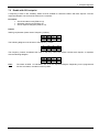
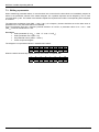
7.3 Writing a parameter
When transferring parameter orders, it must be taken into account that the slave does not immediately respond to
orders in the parameter channel of the master telegram, but a positive response can be delayed by one or more
communication cycles. The master must therefore repeat the required order until the corresponding slave response
is received.
The parameter acceleration time (PNU = 102dec / 66hex) of a frequency inverter should be set to the value 10sec in
parameter set 3. Only the PKW channel is evaluated.
As the acceleration time has a frequency-internal resolution of 0.01sec, a parameter value of 10 / 0.01 = 1000
(3E8hex) must be transferred for 2 sec.
Procedure:
• Select parameter (P 102dec + 1000 = P 1102 = P 44Ehex)
• Select parameter set 3 (IND = 02)
• Set parameter value (1000dec / 3E8hex)
• Check response telegram
The telegram is composed as follows in hexadecimal notation:
3
PKE
24
4
PKE
4E
5
IND
02
6
IND
00
7
PWE
00
8
PWE
00
9
PWE
03
10
PWE
E8
When the order has been fully implemented by the inverter, it responds with
3
PKE
14
34
4
PKE
4E
5
IND
02
6
IND
00
7
PWE
00
8
PWE
00
9
PWE
03
Subject to technical alterations
10
PWE
E8
BU 0070 GB
8 Additional information
8
Additional information
8.1 Repairs
The device must be sent to the following address if it needs repairing:
NORD Electronic DRIVESYSTEMS GmbH
Tjüchkampstraße 37
26605 Aurich, Germany
For queries about repairs, please contact:
Getriebebau NORD GmbH & Co. KG
Telephone: +49 4532 / 401 514 or 401 518
Fax: 04532 / 401-555
If a frequency inverter or accessories are sent in for repair, no liability can be accepted for any added components,
e.g. such as line cables, potentiometer, external displays, etc.!
Please remove all non-original parts from the frequency inverter.
BU 0070 GB
Subject to technical alterations
35
NORDAC InterBus Operating Manual
9
Technical data
Bus connection
Remote bus
Data width
3 words (1 word PCP) ÆPPO type 1
5 words (1 word PCP) ÆPPO type 2
ID
E3hex: with profile
F3hex: without profile
Baud rate
500kBit/sec (2MBaud on request)
External power supply
24V +/-10% *
5V-out at IBS-Out
max. 100mA
* can be operated optionally via internal 5V (e.g. for commissioning)
36
Subject to technical alterations
BU 0070 GB
10 Keyword index
10
Keyword index
2
P
24V....................................................................... 7, 10
PPO type 1............................................................... 13
PPO type 2............................................................... 13
Process data ......................................................23, 24
A
Actual value ....................................................... 26, 27
B
R
Repairs..................................................................... 35
Bus cable ................................................................. 12
Bus configuration ..................................................... 12
Bus parameters ....................................................... 15
S
IW1........................................................................... 26
IW2........................................................................... 27
IW3........................................................................... 27
Setpoint ..............................................................25, 26
SK 300E ..................................................................... 9
SK 500/520E .............................................................. 7
SK 700E ..................................................................... 7
SK 750E ..................................................................... 9
SK TU1-IBS ............................................................... 7
SK TU2-IBS ............................................................... 9
SK TU3-IBS ............................................................... 7
Status LEDs .....................................................8, 9, 21
Status machine ........................................................ 27
Status of the InterBus module ................................. 20
Status word .............................................................. 24
STW ......................................................................... 23
SW1 ......................................................................... 25
SW2/3 ...................................................................... 26
M
T
M12 connector ......................................................... 10
M8 connector ........................................................... 10
Technical Data ......................................................... 36
Transmission times .................................................. 14
O
Z
Object description .................................................... 31
ZSW ......................................................................... 24
C
Control word ............................................................ 23
E
Example telegrams .................................................. 32
F
FE (function earth) ............................................... 8, 11
I
BU 0070 GB
Subject to technical alterations
37
NORDAC InterBus Operating Manual
11
Sales agencies and branch offices
N O R D branches worldwide:
Brazil / Brasilien
NORD Motoredutores do Brasil Ltda.
Rua Dr. Moacyr Antonio de Morais, 700
Parque Santo Agostinho
Guarulhos – São Paulo
CEP 07140-285
Tel.: +55-11-6402 8855
Fax: +55-11-6402 8830
[email protected]
India / Indien
NORD Drivesystems Pvt. Ltd.
21 VEDAS CENTRE
D.P. Road
AUNDH
Pune Maharashtra - 411 057
Tel: +91-2(0)-5889 373
Fax: +91-2(0)-5888 872
[email protected]
Canada / Kanada
NORD Gear Limited
41, West Drive
CDN - Brampton, Ontario, L6T 4A1
Tel.: +1-905-796-3606
Fax: +1-905-796-8130
[email protected]
Indonesia / Indonesien
PT NORD Indonesia
Jln. Raya Serpong KM. 7
Kompleks Rumah Multi Guna
Blok D No. 1
Pakulonan (Serpong) - Tangerang
West Java - Indonesia
Tel.: +62-21-5312 2222
Fax: +62-21-5312 2288
[email protected]
Mexico / Mexiko
NORD GEAR CORPORATION
Mexico Regional Office
Av. Lázaro Cárdenas 1007 Pte.
San Pedro Garza Garcia, N.L.
México, C.P. 66266
Tel.: +52-81-8220-9165
Fax: +52-81-8220-9044
[email protected]
P.R. China / V. R. China
NORD (Beijing) Power Transmission
Co.Ltd.
No. 5 Tangjiacun,
Guangqudonglu, Chaoyangqu
Beijing 100022
Tel.: +86-10-67704 -069 (-787)
Fax: +86-10-67704 –330
[email protected]
P.R. China / V. R. China
Singapore / Singapur
United States / USA
NORD Gear Pte. Ltd.
NORD Gear Corporation
33 Kian Teck Drive, Jurong
Singapore 628850
800 Nord Drive / P.O. Box 367
USA - Waunakee, WI 53597-0367
Tel.: +65-6265 9118
Fax: +65-6265 6841
[email protected]
Tel.: +1-608-849 7300
Fax: +1-608-849 7367
[email protected]
NORD (Suzhou) Power Transmission
Co.Ltd.
地址:苏州工业园区长阳街510号
No. 510 Changyang Street,
Suzhou Ind. Park, Jiangsu, China.
P.C : 215021
总机 Tel:+86-512-85180277
传真 Fax: +86-512-85180278
[email protected]
38
Subject to technical alterations
BU 0070 GB
10 Sales agencies and branch offices
NORD branches in Europe:
Austria / Österreich
Belgium / Belgien
Croatia / Kroatien
Getriebebau NORD GmbH
Deggendorfstr. 8
A - 4030 Linz
NORD Aandrijvingen Belgie N.V.
Boutersem Dreef 24
B - 2240 Zandhoven
NORD Pogoni d.o.o.
Obrtnicka 9
HR - 48260 Krizevci
Tel.: +43-732-318 920
Fax: +43-732-318 920 85
Tel.: +32-3-4845 921
Fax: +32-3-4845 924
Tel.: +385-48 711 900
Fax: +385-48 270 494
[email protected]
[email protected]
[email protected]
Czech. Republic / Tschechien
Denmark / Dänemark
Finland / Finnland
NORD Pohánèci Technika s.r.o
Palackého 359
CZ - 50003 Hradec Králové
NORD Gear Danmark A/S
Kliplev Erhvervspark 28 – Kliplev
DK - 6200 Aabenraa
NORD Gear Oy
Aunankorvenkatu 7
FIN - 33840 Tampere
Tel.: +420-495 5803 -10 (-11)
Fax: +420-495 5803 -12
Tel.: +45 73 68 78 00
Fax: +45 73 68 78 10
Tel.: +358-3-254 1800
Fax: +358-3-254 1820
[email protected]
[email protected]
[email protected]
Great Britain / Großbritannien
Hungary / Ungarn
NORD Réducteurs sarl.
17 Avenue Georges Clémenceau
F - 93421 Villepinte Cedex
NORD Gear Limited
11, Barton Lane
Abingdon Science Park
GB - Abingdon, Oxfordshire OX 14 3NB
NORD Hajtastechnika Kft.
Törökkö u. 5-7
H - 1037 Budapest
Tel.: +33-1-49 63 01 89
Fax: +33-1-49 63 08 11
Tel.: +44-1235-5344 04
Fax: +44-1235-5344 14
[email protected]
[email protected]
Italy / Italien
Netherlands / Niederlande
Norway / Norwegen
NORD Motoriduttori s.r.l.
Via Newton 22
IT-40017 San Giovanni in Persiceto (BO)
NORD Aandrijvingen Nederland B.V.
Voltstraat 12
NL - 2181 HA Hillegom
Nord Gear Norge A/S
Solgaard Skog 7, PB 85
N-1501 Moss
Tel.: +39-051-6870 711
Fax: +39-051-6870 793
Tel.: +31-2525-29544
Fax: +31-2525-22222
Tel.: +47-69-206 990
Fax: +47-69-206 993
[email protected]
[email protected]
[email protected]
Poland / Polen
Russian Federation / Russland
Slowakia / Slowakei
NORD Napedy Sp. z.o.o.
Ul. Grottgera 30
PL – 32-020 Wieliczka
OOO NORD PRIVODY
Ul. A. Nevsky 9
RU-191167 St.Petersburg
NORD Pohony, s.r.o
Stromová 13
SK - 83101 Bratislava
Tel.: +48-12-288 22 55
Fax: +48-12-288 22 56
Tel.: +7-812-327 0192
Fax: +7-812-327 0192
Tel.: +421-2-54791317
Fax: +421-2-54791402
[email protected]
[email protected]
[email protected]
Sweden / Schweden
Switzerland / Schweiz
NORD Drivsystem AB
Ryttargatan 277 / Box 2097
S - 19402 Upplands Väsby
Getriebebau NORD AG
Bächigenstr. 18
CH - 9212 Arnegg
Tel.: +46-8-594 114 00
Fax: +46-8-594 114 14
Tel.: +41-71-388 99 11
Fax: +41-71-388 99 15
[email protected]
[email protected]
France / Frankreich
Spain / Spanien
NORD Motorreductores
Ctra. de Sabadell a Prats de Llucanès
Aptdo. de Correos 166
E - 08200 Sabadell
Tel.: +34-93-7235322
Fax: +34-93-7233147
[email protected]
Tel.: +36-1-437-0127
Fax: +36-1-250-5549
[email protected]
Turkey / Türkei
Ukraine / Ukraine
NORD-Remas Redüktör San. ve Tic. Ltd.
Sti.
Tepeören Köyü
TR - 34959 Tuzla – Istandbul
Tel.: +90-216-304 13 60
Fax: +90-216-304 13 69
GETRIEBEBAU NORD GmbH
Repräsentanz
Vasilkovskaja, 1
office 306
03040 KIEW
[email protected]
[email protected]
BU 0070 GB
Tel.: + 380-44-537 0615
Fax: + 380-44-537 0615
Subject to technical alterations
39
NORD offices in Germany
Getriebebau NORD GmbH & Co. KG
Rudolf- Diesel- Str. 1 ⋅ 22941 Bargteheide
Telephone +49 4532 / 401 - 0
Fax +49 4532 / 401 - 253
[email protected]
www.nord.com
South branches
Getriebebau NORD GmbH & Co. KG
Rudolf- Diesel- Str. 1 ⋅ 22941 Bargteheide
Getriebebau NORD GmbH & Co. KG
Katharinenstr. 2-6 ⋅ 70794 Filderstadt- Sielmingen
Telephone +49 4532 / 401 - 0
Fax +49 4532 / 401 - 253
Telephone +49 7158 / 95608 - 0
Fax +49 7158 / 95608 - 20
[email protected]
[email protected]
Sales office Bremen
Sales Office Nuremberg
Getriebebau NORD GmbH & Co. KG
Getriebebau NORD GmbH & Co. KG
Stührener Weg 27 ⋅ 27211 Bassum
Schillerstr. 3 ⋅ 90547 Stein
Telephone +49 4249 / 9616 - 0
Fax +49 4249 / 9616 - 76
Telephone 0911 / 67 23 11
Telefax 0911 / 689378 - 0
[email protected]
[email protected]
Representative:
Hans-Hermann Wohlers
Handelsgesellschaft mbH
Ellerbuscher Str. 179 ⋅ 32584 Löhne
Telephone +49 5732 / 40 72
Fax +49 5732 / 123 18
[email protected]
West branches
Sales Office Munich
Getriebebau NORD GmbH & Co. KG
Untere Bahnhofstr. 29a ⋅ 82110 Germering
Telephone +49 89 / 840 794 - 0
Fax +49 89 / 840 794 - 20
[email protected]
East branches
Getriebebau NORD GmbH & Co. KG
Getriebebau NORD GmbH & Co. KG
Großenbaumer Weg 10 ⋅ 40472 Düsseldorf
Leipzigerstr. 58 ⋅ 09113 Chemnitz
Telephone +49 211 / 99 555 - 0
Fax +49 211 / 99 555 -45
Telephone +49 371 / 33 407 - 0
Fax +49 371 / 33 407 - 20
[email protected]
[email protected]
Sales Office Butzbach
Sales Office Berlin
Getriebebau NORD GmbH & Co. KG
Getriebebau NORD GmbH & Co. KG
Marie- Curie- Str. 2 ⋅ 35510 Butzbach
Heinrich- Mann- Str. 8 ⋅ 15566 Schöneiche
Telephone +49 6033 / 9623 - 0
Fax +49 6033 / 9623 - 30
Telephone +49 371 / 639 79 - 0
Fax +49 371 / 639 79 - 414
[email protected]
[email protected]
Mat. Nr. 607 0702 / 5205
North branches