1
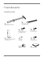
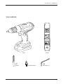
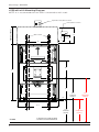
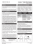
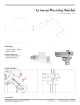
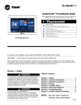
e550
Wallstation
MANUAL 071014
The Enovate Medical e550 Wallstation was designed to set a new standard in quality. Enovate
Medical’s goal is to provide a wallstation ready for years of use and backed by a commitment of
exemplary service and support.
Thank you for purchasing the
Enovate Medical e550 Wallstation!
©2013 Enovate Medical LLC. All Rights Reserved. Content is subject to change without notification.
1
IMPORTANT WARNINGS:
Read the entire installation manual before you begin.
MOUNTING
Installer must verify that the entire wall will safely support the combined weight of all attached
equipment and hardware. Improper installation of this product can cause extensive property damage
or serious personal injury, either during or after installation. It is the responsibility of the installer
to ensure that all applications including wood, concrete, block, brick, steel, etc are secured properly
and are in compliance with local and national building codes. California installations could require
specific anchorage, and additional mounting screws. Check with local authorities for codes in your
area. Other seismic states have similar regulations.
WARNING: Because wall surfaces and construction methods and materials vary, it is imperative that
you consult with the appropriate engineering, architectural or construction professional to ensure
that your Wall computing station is mounted properly to handle the applied loads.
ELECTRICAL SHOCK HAZARD
Cutting or drilling into electrical wires and cables can cause FIRE, DEATH or SERIOUS PERSONAL
INJURY! Always make certain the area behind the mounting surfaces is free of electrical wires and
cables before drilling into wall.
EXPLOSION AND FIRE HAZARD
Drilling into gas plumbing can cause EXPLOSION, FIRE, DEATH or SERIOUS PERSONAL INJURY!
Always make certain the area behind the mounting surface is free of gas, water, waste, or any other
plumbing before drilling.
GROUNDING
Connect the Enovate Medical Wall Station to a grounded receptacle
SERVICE AND REPLACEMENT
Do not attempt to service or replace any part of the Enovate Medical Wall Station unless directed to
do so through Enovate Medical approved documentation (i.e., this User Manual or other instructions).
Only Enovate Medical or an Enovate-certified entity may service or replace the wall station components. If any component on the wall station is missing or damaged, the wall station must not be used.
Contact Enovate Medical immediately to request service.
If the unit is not working properly, please contact Enovate Medical Customer Service toll free at
888.909.8930
or by email at support@enovatemedical .com.
2
Table Of Contents • MANUAL
1
WELCOME
2
WARNINGS
4
HARDWARE
6
MOUNTING
11
HEIGHT RESTRICTION BRACKET
12
COMPONENT INSTALLATION
15
UNIVERSAL CPU BRACKET
16
OPTIONAL WORK SURFACE W/
SLIDE OUT KEYBOARD TRAY
18
ADJUSTMENTS
21
KEYPAD OPERATIONS (Lift &/or Locking Units Only)
3
Hardware
HARDWARE INCLUDED
8x
4x
#10 x 2 1/2”
Pan Head Screw
SNAPTOGGLE® Anchor
2x
1/4-20 x 3/4”
Button Head Screw
(Lift Models Only)
1x
Height Restriction Bracket
(Lift Models Only)
4x
4x
#10 x 1/4”
Standoff
M4 x 16mm
Pan Head Screw
10x
4x
Cable Tie
4
4x
M4 x 12mm
Pan Head Screw
Dual Lock Pads
Hardware • MANUAL
TOOLS NEEDED
Drill
1/2”
Drill Bit
Level
Phillips Head Bit
1/8
Allen Wrench
5
Mounting • MANUAL
e550 with eLift Mounting Diagram
NOTE: It is recommend that the e550 is mounted to wall studs .
Optional Power/Data Location
VERTICAL TRAVEL
Power/Data Location
12"
WALL STUDS
16"
6"
4"
.5” DIAMETER HOLE
15"
45"
.5” DIAMETER HOLE
17"
1.5"
47.5"
IN ROOM
HEIGHT
57"
CORRIDOR
HEIGHT
29.5"
30.5"
IN ROOM
HEIGHT
FLOOR
6
40" MIN. ABOVE FLOOR IF HUNG IN CORRIDOR
+- 30.5 ABOVE FLOOR IF HUNG IN PATIENT ROOM
40"
CORRIDOR
HEIGHT
Mounting • MANUAL
e550 Non-Lift Mounting Diagram
NOTE: It is recommend that the e550 is mounted to wall studs .
WALL STUDS
6"
6.5"
16"
5.2"
Power/Data
Location
5"
7.8"
5.25"
.5” DIAMETER HOLE
15"
45"
.5” DIAMETER HOLE
17"
1.5"
47.5"
IN ROOM
HEIGHT
57"
CORRIDOR
HEIGHT
29.5"
CENTER LINE
FLOOR
30.5"
IN ROOM
HEIGHT
40"
CORRIDOR
HEIGHT
40" MIN. ABOVE FLOOR IF HUNG IN CORRIDOR
+- 30.5 ABOVE FLOOR IF HUNG IN PATIENT ROOM
7
Mounting
In-Room Installation
STEP 1
Determine your desired keyboard height. The dimensions on drawing
(see page 6 and 7) are shown for a keyboard height range of 30.5" to
42.5". Adjust dimensions as required for desired height.
STEP 2
Locate the exact center line of the wall studs.
STEP 3
Using a level, mark two horizontal lines at the distance from finish
floor shown on the drawing on page 6 and 7.
STEP 4
Drill (4) ½” holes through the center of the wall studs and install
(4) SNAPTOGGLE® brand hollow wall anchors. (See wall anchor
installation instructions on page 10.)
STEP 5
Screw Wallstation to the wall using the #10 Pan Head Screws provided.
Check the Wall Station for level before tightening completely.
Corridor Installation
STEP 1
FOR CORRIDOR INSTALLATION THE WALLSTATION IN CLOSED
POSITION MUST BE A MINIMUM OF 40" ABOVE FLOOR AND 2"
ABOVE CORRIDOR HANDRAIL OR ANY OBSTRUCTION (PER CMS
REGULATIONS).
STEP 2
Locate the exact center line of the wall studs.
8
STEP 3
Using a level, mark two horizontal lines at the distance from finish
floor shown on the drawing.
STEP 4
Drill (4) ½” holes through the center of the wall studs and install
(4) SNAPTOGGLE® brand hollow wall anchors. (See wall anchor
installation instructions on page 10.)
STEP 5
Screw Wallstation to the wall using the screws provided. Check the
Wallstation for level before tightening completely.
METAL STUD MOUNTING
Back Plate
Wall
Track
Metal Stud
SNAPTOGGLE®
#10x2 1/2”
Pan Head Screw
9
Mounting • MANUAL
SNAPTOGGLE® HOLLOW WALL ANCHOR INSTALLATION
STEP 1
Drill a ½" hole through center of metal stud. Hold metal
channel flat alongside plastic straps and slide channel
through hole.
1/2”
Must be 1-7/8” minimum
clearance 1/2”
behind wall for
channel rotation.
1/2”
Metal Stud
Must be 1-7/8”
3/8” -minimum
3 5/8”
clearance behind
wall for
Thick
Must
be
1-7/8” minimum
channel rotation.
clearance behind wall for
channel rotation.
STEP 2
Hold ends of straps between
thumb and forefinger and
pull toward you until channel
rests flush behind wall. Slide
plastic cap along straps with
other hand until flange of cap
is flush with wall.
3/8” - 3 5/8”
Thick
3/8” - 3 5/8”
Thick
Metal Stud
Metal Stud
Metal Stud
Metal Stud
Metal Stud
STEP 3
Snap straps at wall by pushing side to side, snapping off
straps level with flange of cap.
Patented under one or more of the follow ng U.S. Patent Nos.: 4,993,901; 5,028,186; 5,161,296;
5,938,385; 6,161,999; 7,144,212; 7,320,569; and foreign counterparts thereof and of 4,650,386 and
4,752,170. Other patents pending.
TOGGLER and typeface, symbol, TA, TB, TC, TH, ALLIGATOR, SNAPTOGGLE, and SnapSkru are
worldwide registered trademarks of Mechanical Plastics Corp.
10
(eLift Models Only)
Height Restriction
Bracket - Optional
The e550 has an optional height restriction bracket that can be installed
if there is a low ceiling condition where vertical travel is limited. Refer to
the following diagrams for three mounting options. The height restriction
bracket should only be used to prevent ceiling damage. When the wall
station comes into contact with the bracket it will shut the unit off.
OPTION 1
Restricts vertical movement to 6" total.
OPTION 2
Restricts vertical movement
to 8" total.
OPTION 3
Restricts vertical movement
to 10" total.
11
Component Installation
MONITOR INSTALLATION
STEP 1
Unlock and open the component door
and display glass.
STEP 2
Remove VESA plate Thumb Nuts
and remove the VESA plate from the
wall station
STEP 3
Mount VESA plate to monitor using
the (4) M4x12 pan head screws
provided.
12
STEP 4
Attach monitor and VESA plate assembly into wall station with the
Thumb Nuts. Do not fully tighten to allow for adjustment. (PLUG
POWER CORD FROM WCC CONTROLLER INTO MONITOR)
STEP 5
Close the display glass
13
Component Installation • MANUAL
STEP 6
Ensure that monitor is placed in the center of the frame and tighten
thumb screws.
14
CPU Bracket
The e550 is equipped with a universal CPU bracket that will accommodate
CPU's with maximum dimensions of 10.5"x 10.5"x 2.6".
STEP 1
Loosen thumb screw and move
CPU bracket to its upper most
position.
STEP 2
Put the CPU in place
STEP 3
Loosen thumb screw and move
the CPU bracket so it snugly
holds the CPU in place. Tighten
thumb screw.
15
Optional Work Surface w/
Slide out Keyboard Tray
STEP 1
Slide out keyboard tray
STEP 2
Remove (4) screws
16
Optional Work Surface w/ Slide out Keyboard Tray • MANUAL
STEP 3
Plug mouse and keyboard USB cords into pre-wired jack.
Using cable ties secure excess wire to tie pads.
NOTE: Leave just enough slack
for keyboard tray to slide all
the way out
STEP 4
Replace (4) screws
17
Adjustments
KEYBOARD TRAY GAS SPRING ADJUSTMENT
STEP 1
To adjust the keyboard tray
closing tension, turn adjustable
gas spring bracket screw.
Turn clockwise to increase
tension and counterclockwise to
decrease tension.
NOTE: Do not over adjust as this may defeat
the closing mechanism.
ADJUSTING THE CPU DOOR HINGES FOR PROPER DOOR ALIGNMENT
LATERAL ADJUSTMENT
Turn front spiral-tech cam screw
to increase or decrease door
overlay.
DEPTH ADJUSTMENT
Turn rear spiral-tech cam screw
to adjust door position.
HEIGHT ADJUSTMENT
Rotate cam screw on plate to
adjust door position
18
Adjustments • MANUAL
FINISHING UP eLIFT (non-lift see page 20)
1. Attach the USB cable from the WCC Controller Box to the PC.
2. Plug LCD VGA cable into CPU.
3. Plug the power from the three way splitter to the PC Power.
To AC Power
Actuator Power Brick
To PC USB
Three Way
Power Splitter
To PC Power
USB OUT
KEYBOARD
LIGHT
USB
IN
MED ACTUATOR MAGNETS &
LOCK
PWR
LIMIT SWITCH
12V
POWER IN
Wall Station Controller
SENSOR
MONITOR
POWER
OUT
KEYPAD
WARNING
120V
POWER IN
CHASSIS
GROUND
WCC
Controller Box
Monitor Power
WCC - CONTROLLER BOX
THREE WAY SPLITTER
To AC Power
Pre Wired for
Keyboard & Mouse
To PC
USB OUT
KEYBOARD
LIGHT
Three Way
Power Splitter
USB
IN
MED ACTUATOR MAGNETS &
LOCK
PWR
LIMIT SWITCH
12V
POWER IN
Wall Station Controller
SENSOR
MONITOR
POWER
OUT
KEYPAD
To Monitor
WARNING
120V
POWER IN
CHASSIS
GROUND
Pre Wired
From Power Splitter
Pre Wired
To WCC Power In
Pre Wired To
Power Brick
To PC Power
19
FINISHING UP NON-LIFT
1. Attach the USB cable from the WCC Controller Box to the PC.
2. Plug LCD VGA cable into CPU.
3. Plug the power from the two way splitter to the PC Power.
To AC Power
To PC USB
Two Way
Power Splitter
Additional Power
To PC Power
USB OUT
KEYBOARD
LIGHT
USB
IN
MED ACTUATOR MAGNETS &
LOCK
PWR
LIMIT SWITCH
12V
POWER IN
Wall Station Controller
SENSOR
MONITOR
POWER
OUT
KEYPAD
WARNING
120V
POWER
WCC
Controller Box
IN
CHASSIS
GROUND
Monitor Power
WCC - CONTROLLER BOX
THREE WAY SPLITTER
To AC Power
Pre Wired for
Keyboard & Mouse
To PC
USB OUT
KEYBOARD
LIGHT
USB
IN
Three Way
Power Splitter
MED ACTUATOR MAGNETS &
LOCK
PWR
LIMIT SWITCH
12V
POWER IN
Wall Station Controller
SENSOR
MONITOR
POWER
OUT
KEYPAD
To Monitor
20
WARNING
120V
POWER
IN
CHASSIS
GROUND
Pre Wired
From Power Splitter
Pre Wired
To WCC Power In
Additional
Power Source
To PC Power
3. Mount keyboard to keyboard tray with supplied 3M™ Dual Lock™
Squares. Be sure keyboard does not cover round metal plate.
4. Plug keyboard and mouse into the USB hub that is pre-wired into
the keyboard tray.
Cleaning Instructions:
• Use non abrasive cleaners or mild cleaning solutions.
• Do not use abrasive cleaners, solvents, polishes, waxes or steam cleaning tools.
• A s a precaution to test the suitability of a cleaning product, apply to an inconspicuous area, minimizing the time of exposure and the amount of cleaning agent (diluting as recommended by the supplier) in order to prevent any damage to the surface.
• C ontamination by intensively colored substances, for example coffee, mustard,
curry or red wine, have to be removed immediately.
21
Keypad Operations
(Electronic Lift &/or Locking Units Only)
1
2
3
4
5
Keypad
There are five keys that are used to enter 5-digit PIN codes.
LED
A single multi-color LED on the keypad provides feedback to the user
as key sequences are pressed. The LED can appear as green or red.
LED COLOR
FLASH ONCE
FLASH TWICE
Green
Each key press
Successful operation
Red
N/A
Failed operation or timeout
Master Code
There is one, 5-digit Master PIN Code for use by the system administrator. The Master Code is used to assign User PIN Codes and for other
maintenance functions.
The factory default Master Code is 12345.
User PIN Codes
Up to 100, 5-digit PIN Codes can be assigned for use by hospital
personnel to access the wall cabinet keyboard. When a user enters
their valid PIN code, the keyboard drawer unlocks and can be opened
by user to allow access. Additionally the LCD monitor is turned on
and additional keys on the keypad become enabled for adjusting the
height of the wall unit, turning on the optional keyboard light and for
closing the keyboard drawer.
The factory default User PIN Code is 54321.
22
Keypad Operations • MANUAL
Reserved PIN Codes
The following PIN codes are reserved for administrative usage. These
codes cannot be assigned as either the Master Code or as a User PIN Code.
PIN CODE
DESCRIPTION
13321
Turn on USB. Keypad behaves like a keyboard for the PC.
13322
Turn off USB.
13323
Set the Open mode.
13324
Set the Close mode.
13325
Reserved for future use.
13331
Set the keyboard light opening state.
13332
Set the proximity sensor delay time.
13333
Report configuration over USB (to a text editor).
13334
Reserved for future use.
13335
Reserved for future use.
13341
Delete a user PIN code.
13342
Delete all user PIN codes and restore default user PIN code 54321.
13343
Set the keyboard tray unlock time.
13344
Add a user PIN code.
13345
Reserved for future use.
13351
Enter the bootloader to upgrade the embedded firmware.
Factory Defaults Summary - For Locking Units
All units are shipped from the factory with the following default values:
ITEM
DEFAULT VALUE
Master Code
12345
User PIN Code
54321
Keyboard Tray Unlock Time
2 seconds
USB Interface
On
Keyboard Light Opening State
On
Proximity Sensor Delay Time
30 seconds
Open Mode
User PIN only
Close Mode
Prox timeout, Close switch or door close.
23
Keypad Operations • MANUAL
USER FUNCTION
LOCKING KEYBOARD TRAY - PIN
TO OPEN:
1. Enter your assigned PIN code, wait until green light flashes.
(DO NOT PRESS THE
BUTTON)
2. Pull keyboard tray down.
3. Log on to computer.
NOTE: You must be standing in front of the wallstation for keyboard tray
to remain open.
TO CLOSE:
1. Log off computer.
2. Slide mouse toward back of keyboard tray, away from edge.
3. Press
to close keyboard tray.
NON LOCKING KEYBOARD TRAY
TO OPEN:
1. Pull keyboard tray down.
2. Log on to computer.
NOTE: You must be standing in front of the wallstation for keyboard tray
to remain open.
TO CLOSE:
1. Log off computer.
2. Slide mouse toward back of keyboard tray, away from edge.
3. Press
24
to close keyboard tray.
Keypad Operations • MANUAL
(eLift Models Only)
1
2
3
4
5
Adjusting the Wall Unit Height
1. P
ress and hold the Up or Down
switch to adjust the height of the
wall unit. There is a 12" height
adjustment from the lowest
keyboard height unless the height
restriction bracket has been
installed.
Activating the Keyboard Light
1. Press the
logo on the keypad to turn the light on.
2. Press the
logo again to turn the light off.
25
Keypad Operations • MANUAL
Administrative Functions
All code entries require five key presses. Too few or too many key
presses will result in a failed operation. NOTE: All administrative functions must be completed with the keyboard tray in the closed position.
Please note that in all of the following examples it is advised to have all
key strokes written down for the desired operation. If there is a pause
of 2 seconds or longer between any two keys the red LED will flash
twice to indicate a failure. To cancel an operation, stop pressing keys
and let the operation fail due to a timeout. When an operation completes successfully there will be two green flashes.
Changing the Master Code
1. Enter the current Master Code.
2. Enter the current Master Code again.
3. Enter the new Master Code.
4. Pause for 2 seconds.
5. The green LED flashes twice for success. The new Master Code
has been saved and activated.
IMPORTANT: RECORD YOUR MASTER CODE AND SAVE IT IN A SAFE PLACE.
Adding a User PIN Code
1. Enter the Master Code.
2. Enter 13344.
3. Enter the PIN Code to add.
4. Pause for 2 seconds.
5. The green LED flashes twice for success. The PIN Code has been
saved and activated.
Deleting a User PIN Code
1. Enter the Master Code.
2. Enter 13341.
3. Enter the PIN Code to delete.
4. Pause for 2 seconds.
5. The green LED flashes twice for success. The PIN Code has been
deleted.
Deleting All User PIN Codes and Restoring the Default PIN Code
1. Enter the Master Code.
2. Enter 13342.
3. Pause for 2 seconds.
4. T
he green LED flashes twice for success. All User PIN Codes have
been deleted and the factory default PIN code 54321 restored.
26
Keypad Operations • MANUAL
How to Turn On the USB Interface
1. Enter the Master Code.
2. Enter 13321.
3. Pause for 2 seconds.
4. T
he green LED flashes twice for success. The new state has
been saved and activated. When the USB interface is turned on,
key presses will be sent to the PC over USB just like a standard
keyboard.
How to Turn Off the USB Interface
1. Enter the Master Code.
2. Enter 13322.
3. Pause for 2 seconds.
4. T
he green LED flashes twice for success. The new state has
been saved and activated
How to Set the Keyboard Light Opening State
1. Enter the Master Code.
2. Enter 13331.
3. Enter 11111 to turn the light on, or 11112 to turn the light off at
open.
4. Pause for 2 seconds.
5. The green LED flashes twice for success. The new opening state
has been saved and activated
How to Set the Open Mode for the Unit
1. Close the keyboard tray by pressing the Close switch.
2. Enter the Master Code.
3. Enter 13323.
4. Enter the Open Code for the desired Open Mode from table below.
5. Pause for 2 seconds.
6. T
he green LED flashes twice for success. The new Opening mode
has been saved and activated.
OPEN MODE
DESCRIPTION
OPEN CODE
1
Open by User PIN only.
11111
2
Open by User PIN or Close button press.
11112
3*
Open by pulling down the keyboard tray.
11113
* Option 3 is for non-locking units only.
27
Keypad Operations • MANUAL
How to Set the Close Mode for the Unit
This option determines when the monitor will turn off. The first option
turns the monitor off when the proximity sensor timeout period expires
due to the user walking away, the user pushes the Close button, or the
keyboard tray is closed by the user. The second option turns off the
monitor only when the keyboard tray is actually closed all the way.
1. Close the keyboard tray by pressing the Close switch.
2. Enter the Master Code.
3. Enter 13324.
4. E
nter the Close Code for the desired Close Mode from the table
below.
5. Pause for 2 seconds.
6. T
he green LED flashes twice for success. The new Closing mode
has been saved and activated.
7. Press the Close switch.
CLOSE MODE
DESCRIPTION
CLOSE CODE
1
Prox Timeout, Close Switch or Door Close.
11111
2
Door Close.
11112
How to Set the Proximity Sensor Delay Time
1. Enter the Master Code.
2. Enter 13332.
3. Enter the 5-digit time code for the required delay time from the
table below.
4. Pause for 2 seconds.
5. The green LED flashes twice for success. The new Delay Time
has been saved and activated.
DELAY TIME
TIME CODE
DELAY TIME
TIME CODE
3 sec
11111
2 min
11131
5 sec
11112
3 min
11132
7 sec
11113
4 min
11133
10 sec
11114
5 min
11134
15 sec
11115
7 min
11135
20 sec
11121
10 min
11141
30 sec
11122
12 min
11142
40 sec
11123
15 min
11143
50 sec
11124
20 min
11144
60 sec
11125
Disabled
11145
28
Keypad Operations • MANUAL
How to Set the Proximity Sensor Range
1. Enter the Master Code.
2. Enter 13325.
3. Enter the 5-digit range code for the proximity sensor from the
table below
4. Pause for 2 seconds.
5. The green LED flashes twice for success. The new range has
been saved and activated.
RANGE
RANGE CODE
INCHES
CM
20
51
11111
30
76
11112
40
102
11113
50
127
11114
60
152
11115
29
30
31
32
33
1152 Park Avenue
Murfreesboro, TN 37129
p. (888)909-8930 f. (615)896-8906
www.enovatemedical.com
[email protected]
©2014 Enovate Medical LLC. All Rights Reserved