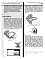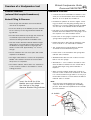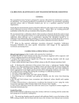
1
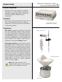
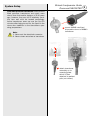
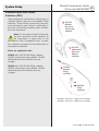
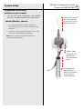
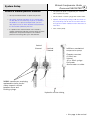
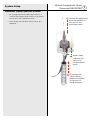
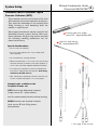
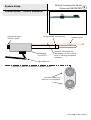
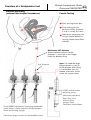
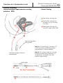
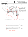
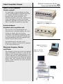
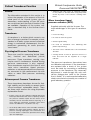
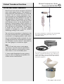
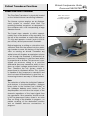
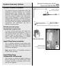
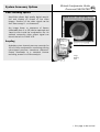
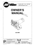
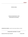
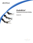
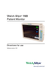
Clinical Urodynamics Guide
Document No. NSO1875D
Revised: 17.07.99
The purpose of this guide is not to describe
the clinical reasons for urodynamic diagnostic
testing, but to give a general outline of the
mechanics of the test. The actual sequences
and methods utilised may vary from lab to lab.
References to equipment and their operation
are clarified in later revisions.
This document contains clinical diagrams for
pressure transducer and catheter setup.
Some diagrams are representations and may
not accurately depict certain equipment. It is
intended as a guide only.
This document is under revision, some
sections may not contain the latest
information on some of our new products.
Some procedures are under revision to
include these new products,
Please contact Neomedix Systems if you have any
problems or suggestions regarding this document or
require more detailed information for system setup
Tel:
Fax:
eMail:
netSite:
+612 9913 8044
+612 9913 7818
[email protected]
http://neomedix.com
System Setup
Clinical Urodynamics Guide
Document NSO1875D 2
General Preparation
Because of the many variations in testing
procedures it is not possible to dictate any
standard in patient preparation. Follow the
normal procedures adopted by your
department.
Acquidata
Ensure the system has been turned on for at
least 10 minutes before a test to allow all
components (mostly the pressure transducers)
to thermally stabilise.
acquiamplifier (top) &
acquiprocessor (bottom)
Transducers
Fill volume: suspend the infusion bag, filled
with the appropriate bladder filling solution,
from the fill volume hook and position the delivery tubing such that it is not under tension. If
a powered filling pump is used, the tubing from
the infusion bag feeds to the inlet fitting on the
pump tubeset. The tubeset output fitting is
connected to the patient filling catheter.
filling volume sensor
Void volume and flow: ensure that the receiving chamber has a small amount of liquid in
the bottom, which is enough to just cover the
bottom of the central tube. Position the receiving chamber upon the holding platform and
position it under the voiding commode. Attach
the funnel splash cover for male use when not
using the commode. The optional turbulence
reducer plug may also be placed in the funnel
when urine flow has a tendency to be focused
directly above the funnels central area (this
added kinetic energy can cause increased
noise in the flow signal).
receiving chamber
Note: Some later models of the
Uromac system may not use a holding
platform and weighing transducer
flow sensor
System Setup
Fluid filled pressure transducers: External fluid
filled pressure transducers are much more
robust than their earlier designs of 5-10 years
ago, however, they are still a relatively sensitive item and must be treated accordingly.
Active transducers warm up over the first 10
minutes after being turned on, the liquid in the
dome also stabilises to the transducers operating temperature.
Note:
1. Never wet the electrical connector.
2. Never steam autoclave a transducer
Clinical Urodynamics Guide
Document NSO1875D 3
1 mount MX848 sterilised
disposable dome to MX860
transducer
2 attach transducer
assembly on to
mounting plate
which is then
attached to patient
pole (not shown)
System Setup
Clinical Urodynamics Guide
Document NSO1875D 4
Standard Fluid Filled Patient
Catheters (FFC)
Have prepared for connection a sterile pack of
standard patient pressure and bladder filling
catheters. These will be connected to the pressure transducers (and saline or water bag in
the case of the filling catheter) after introduction into the patient.
Note: For the sake of clarity of description the connection of the catheters to
the transducers is given prior to the
description of the ‘urodynamics test’. In practice, catheters are placed in the patient prior to
transducer connection.
These are supplied as kits:
UD-001 with 14F UD-005 filling catheter,
UD-004 vesical pressure catheter, UD-003
abdominal pressure catheter and two
syringes.
UD-002 with 10F UD-005 filling catheter,
UD-004 vesical pressure catheter, UD-003
abdominal pressure catheter and two
syringes.
A UD-004
bladder
pressure
monitoring
catheter
B UD-003
abdominal
pressure
balloon
catheter
C UD-005
bladder
filling
catheter
D MX634L
4-way
stopcock
• UD-005 in 14F size is supplied in kit UD-001
• UD-005 in 10F size is supplied in kit UD-002
• this page to be revised
System Setup
Clinical Urodynamics Guide
Document NSO1875D 5
Preparation of fluid filled
patient pressure channel
Use normal sterile techniques and hospital
protocols as appropriate for this procedure.
Vesical (Bladder) channel
3 connect the vesical
pressure catheter
to this port on the
transducer dome
• Fill a syringe with sterile saline or water and
connect it to the luer port of the vesical pressure
transducer.
• Connect the vesical pressure catheter to the other
port of the vesical pressure transducer.
Note: This is usually done after the catheter is
introduced into the patient
2 attach 4-way
stopcock this
luer port of
the transducer
dome
1 fill syringe with
sterile saline or
water and connect
to luer port of
4-way stopcock
Clinical Urodynamics Guide
Document NSO1875D 6
System Setup
Vesical & Urethral pressure channels
• The perfused liquid is supplied by the mechanical compression pump
• Set up vesical transducer as previously shown.
• Fill the 10mL or 30mL syringe with sterile water.
• Set up the urethral transducer as for vesical channel but add the second 4-way stopcock to facilitate
the addition of a pressurised perfused (low flow
rate) liquid source to allow accurate measurements
for the urethral sphincter pressure.
• Operate the pump by turning to on the switch on
the pump body until all the air has been flushed
through the urethral catheter lumen and interconnect tube.
• In operation the urethral lumen of the vesical /
urethral multilumen catheter measure both pressure
and passes the perfused liquid to the urethral
pressure monitoring side eye in the catheter.
Vesical
Channel
• Turn off the pump.
Urethral
Channel
InfuPress mechanical
compression pump
Flowrate: constant
0.03mL/sec
Volume:
10 or 30mL syringe
Perfusate:
Sterile water or saline.
MX860 transducers employing
replaceable sterile domes.
4-way stopcock utilised
between dome and
flushing syringe.
Hydraulic resister tubing
• this page to be revised
System Setup
Clinical Urodynamics Guide
Document NSO1875D 7
Abdominal (Rectal) pressure channel
• Fill a syringe with sterile saline and connect to a
sterile 4 way stopcock which in turn is connected to
the luer port on the transducer dome.
• Flush through the transducer dome until all air is
displaced.
3 connect the abdominal
pressure catheter to
this port on the
transducer dome
2 attach 4-way
stopcock this
luer port of
the transducer
dome
1 fill syringe with
sterile saline or
water and connect
to luer port of
4-way stopcock
System Setup
Clinical Urodynamics Guide
Document NSO1875D 8
Alternative Micro Transducer Tipped
Pressure Catheters (MTC)
These devices can be used instead of the fluid
filled catheter connected external transducers.
They have the advantage of not requiring fluid
filling, flushing or zero balancing when the
patient is repositioned.
Micro tipped transducers can be used with the
Acquidata Uromac system directly. With care,
these catheters will give long service provided
the following handling precautions are followed meticulously.
Special Considerations:
A closeup view of a single
sensor 5F - polyurethane MTC
B view of a dual sensor
8F - polyurethane MTC
• Do not 'kink' the catheter.
• Do not coil the catheter into loops smaller than
20cm diameter.
• Do not handle the sensing element.
• When the transducer is not in use cover the sensing
elements with the protective cover tube supplied, or
store in the optionally supplied calibration burettes.
A
B
• To sterilise the transducer follow the manufacturer
instructions supplied with the catheter. Autoclaving
will destroy the MTC devices.
• Take care that the electrical connector end does not
come in contact with liquids or corrosive gases.
Standard units available for the
Acquidata Uromac are:
P5FU Vesical and Abdominal channels
(single sensor 5F - polyurethane)
and for predominately female urethral testing:
2P8FLU Vesical and Urethral channels
(dual sensor 8F with filling lumen polyurethane)
• this page to be revised
Clinical Urodynamics Guide
Document NSO1875D 9
System Setup
Powered Vesical / Urethral Withdrawal
withdrawal speed
selector switch
spring biased securing clip
withdrawal
unit UPP01
catheter guide
catheter introduced into
the bladder via the urethra
prior to starting withdrawal
operation
adjustable arm
footswitch cable to withdrawal unit power module
I
footswitch pads for
insertion or withdrawal
W
• this page to be revised
System Setup
Electromyography (EMG)
EMG Option
The EMG option allows the recording of muscle activity to be recorded simultaneously
with other urodynamic signals. The option
comprises four items:• The EMG amplifier inherent within the
AcquiAmplifier.
• The active input patient headstage (NT462F).
• An external audio amplifier and loudspeaker.
• The patient leadwires and electrode kit.
The EMG amplifier is a high gain device, different from those used for normal pressure
and other transducer monitoring. For
Urodynamic applications the output can be
selected as the raw input signal or a integrated (200ms) envelope of the input signal. The
amplifier has a fully isolated input stage for
patient protection.
EMG Range
To select the desired sensitivity for an input
signal range from 100 uV to 50 mV using the
knob control on the extreme right/side of the
AcquiAmplifier. For each selected range an
input signal of the indicated range in amplitude will produce a full scale output of 1.0
Vpp. to the ADC in the AcquiProcessor.
Volume
A single turn control for adjustment of the
EMG signal volume is available on the speaker supplied. During electrode or cable
replacement, the speaker can be turned off
to remove loud artifact noises.
Optional EMG
needle electrode
(dual concentric bipolar)
Clinical Urodynamics Guide
Document NSO1875D 10
Operating Procedure
• Connect the audio output to the remote speaker.
• Connect the patient electrode and interconnect
with the leadwires connectors to the active head
stage input (NT462F).
• Select the range switch to a suitable setting
which, in most cases, will be approximately 1mV
or greater sensitivity. Monitor the quality of the
audio signal aurally until the recording electrodes
are correctly positioned and recording the urethral
electromyographic activity synchronous with
patient voiding.
• Select 'Integrated' EMG using the rear panel
switch on the AcquiAmplifier. This optional integrated EMG will now be displayed if a smoothed
envelope display is preferred.
• A suggested sampling rate of 100 samples/division will give a more detailed raw data display.
Electrodes
1. The ability to selectively record from the desired
muscle is best when carried out with needle electrodes and least when using surface electrodes.
2. Suitable electrode systems are available from
Neomedix Systems or your Acquidata distributor.
3. Any of the following electrode systems can be
used with this system:
• Needle electrodes (dual concentric Bipolar).
• Surface electrodes, preferably of the silver-silver
chloride type, which are generally situated over
the perineum.
• Biologically inert stable recording wires connected
to a urethral catheter. Usually these wires are
made of nichrome or medical grade stainless
steel,
• or alternatively, an anal plug with conductive ring
electrodes.
Detailed Neurohysiological Investigation
For carrying out EMG recordings in the
Neurophysiological investigation (high speed
sweep) mode when monitoring single fibre
responses or pudendal nerve conduction velocities (requiring a current stimulator), refer to the
the separate scope mode EMG option.
Information on the EMG/NCV option for the
Acquidata system is available from your supplier.
System Setup
General Test of System
Filling Volume, Voiding Volume, Pressures &
Voiding Flow: Launch the Uromac application
software using the desired settings file (usually located in the calibration folder and
accessed via the Apple Menu) for the test. The
settings file will need to have been set up for
all the preferred recording parameters and calibrations to suit you site. Refer to the Uromac
User's Guide for details in maintaining and creating new settings files. This also explains how
and where to store you settings.
Void Volume: Place the urine receiving chamber onto the holding platform (if you system
was delivered with this option). Connect to the
appropriate AcquiAmplifier connector.
Fill Volume: Ensure that the fill volume transducer has the required liquid source hanging
on the hook and that all the tubing and connectors are in place. The physical arrangement
should be setup as it is intended to be used.
Connect to the appropriate AcquiAmplifier connector.
Void Flow: There must be enough fluid in the
receiving chamber to cover the bottom of the
central tube (to form a water trap), otherwise
there will be no flow recording until the urine
height reaches the central tube.
Check the appropriate display range is being
used (typically 0-50mL per second). Ensure
there is no flow. Zero balance the trace and the
trace will force to the zero position. Now any
liquid introduced through the funnel assembly
(urine flow) will enter the enclosed internal volume of the receiving chamber. As the urine
level rises it will displace air through the
mechanical flow head sensor and cause the
screen trace to move upwards. Connect to the
appropriate AcquiAmplifier connector.
Pressures: Setup the pressure transducers as
previously described and connect the interconnect cables to the appropriate AcquiAmplifier
connectors.
Clinical Urodynamics Guide
Document NSO1875D 11
Recording
Press start (bottom right of screen or F13 on
the keyboard). As filling and/or voiding commences the respective screen traces will
move from right to left as they would on a
paper chart recorder. Should an inappropriate display range have been selected, the
range can be altered by selecting a new
range from the 'Range' menu (the small
down arrow to the left of each channel title
on the right side of each waveform trace). A
greater value will increase the display range
reducing sensitivity. Selecting a value either
side of the default setting will typically double
or half the display range. Larger changes are
rarely required.
If the range needs to be altered by a smaller
amount (usually for screen cosmetics) the
actual display range can be set using the
'Set Scale' menu (select the small down
arrow to the left of each of the waveform
trace displays). Do not alter the range more
than +/– 30% of the default value using this
technique.
Zero Balancing
Three methods are available to zero the
transducers, either globally by pressing the
'Balance' push button on the AcquiAmplifier
front panel or using the F15 key on the keyboard. Alternatively all or any one of each
each parameter can be balanced using the
Uromac software. This is done through the
Uromac Zero menu. Individually balancing
one transducer channel is useful when only
that transducer channel needs to be reset
(for example, if the volume requires resetting
prior to a second bladder filling).
Operating any of the these balancing mechanisms will offset any recorded input value on
that transducer channel and force the trace
for that channel to the zero position on the
screen.
Overview of a Urodynamics test
The purpose of this section is not to describe
the clinical reasons for urodynamic diagnostic
testing, but to give a general outline of the
mechanics of the test. The actual sequences
and methods utilised may vary between
laboratories. Specific references to equipment and its operation are clarified in later
revisions.
Clinical Urodynamics Guide
Document NSO1875D 12
After the patient has emptied their bladder
the technician or doctor may record the
residual bladder volume by ultrasound or by
introducing a 'Foley' drainage catheter into
the bladder to drain the residual urine into a
measuring container and the volume noted.
No computer measurement is needed at this
point.
Pre-Main Test
Initial Voiding Test
The patient is commonly asked to come in for
the test with a full bladder. Upon arrival the
patient is asked to void (empty their bladder)
into the voiding flow/volume transducer funnel
mounted under the commode. No pressure
transducers or bladder/abdominal catheters
are connected to the patient at this time. The
flow rate whilst voiding (Void Flow) and volume
voided (Void Volume) parameters are recorded. The flow range is usually within 0-50
ml/sec and the volume range 0-800 ml.
drainage flow
volume
Catheterisation
note: no patient connections
At this point the patient will have the relevant
catheters placed by the technician or the
doctor. For the male patient this is generally
limited to a Vesical (bladder) and Abdominal
(rectal) catheter to record pressures, and a
larger diameter Vesical catheter introduced
for bladder filling. If appropriate for the
patient symptoms, urethral pressures may
also be measured although this measurement is more frequently made on female
patients (this can be a second sensor in a
micro transducer tipped catheter or an additional lumen in a fluid filled pressure sensing
catheter).
Please review the following pages describing
both the catheterisation site and connection
of the catheters to the transducers.
Overview of a Urodynamics test
Catheter Insertion
(external fluid coupled transducers)
Vesical Filling & Pressure
• Flush through the transducer dome and catheter
until all air is displaced.
• Insert the distal tip of the bladder pressure catheter
into the side eye of the large diameter bladder filling catheter.
• Introduce both catheters up through the urethra as
a combination pair until the distal ends are
assumed as being well above the bladder neck.
Clinical Urodynamics Guide
Document NSO1875D 13
Abdominal Pressure
• Connect the sterile rectal balloon catheter to the
other port of the transducer dome and introduce
about 6 - 8 ml of liquid into the balloon.
• Hold balloon upwards as shown in Figure 2 holding your thumb over and gently pushing down on
the balloon to hold the trapped internal air bubble
over the end of the catheter inside the balloon.
• Pull back on the syringe withdrawing the air bubble back down the catheter into the syringe. Close
the stopcock off to the transducer dome.
• Push down on the syringe to expel the air in the
syringe. Refill syringe if required.
• Hold the smaller diameter catheter between finger
and thumb of one hand and introduce further into
the bladder the larger catheter using finger and
thumb of other hand. Approximately 1 to 2 cm is
enough.
• Repeat the balloon filling and air aspiration until
most of the air is out of the balloon catheter.
• The two catheters will now move apart and remain
separate in the bladder.
• Fit the dome to the transducer with syringe and
catheter still connected.
• The larger sized catheter is used to fill the patient's
bladder. This catheter can then be removed after
this process is completed.
• Withdraw all but about 2-3ml of saline from the
balloon into the syringe.
• The smaller catheter, which offers less obstruction
to urine outflow, remains in the bladder to record
voiding pressures.
• The syringe/dome/stopcock/balloon catheter
should be a closed fluid filled system.
• With about 2 - 3 ml of saline in the balloon introduce the balloon catheter into the rectum with a
gloved index finger using sterile lubricant if
required.
• When correctly located operate the stopcock to
return 5 to 6ml of saline into the balloon. The balloon should contain enough saline to loosely 3/4
fill the balloon before a volume where the balloon
material starts to stretch.
insert the distal tip of the
bladder pressure catheter into
the side eye of the large
diameter bladder filling catheter
Note:
Some the later rectal catheter kits utilise an
'open/slit' balloon simplifying the de bubbling
process. Flush these as explained for the vesical
pressure catheter.
air bubble
saline
Clinical Urodynamics Guide
Document NSO1875D 14
Overview of a Urodynamics test
Pressure Recording
(external fluid coupled transducers)
Female Testing
A Pves sensing lumen port.
C
B Pura sensing port for
perfused lumen. Distance
A to B is usually 5 to 6cm.
A
B
C Pabd active measuring site
using a special balloon or
sensing sheath liquid filled
catheter.
Multi-lumen UPP Catheter
Several catheter options can be
employed – some with a third larger
lumen for bladder filling.
2nd Stopcock
Note: The separate larger
filling catheter is used to
fill the bladder. After filling
it is withdrawn from the
bladder urethra as shown
under the system setup.
UTRAZ urethral lumen
perfusing pump.
(electrically operated)
Rate: 5mL min-1
Volume: 50mL
Syringe: 50mL
Perfusate: Sterile Water
Three MX860 transducers employing replaceable
sterile domes. 4-way stopcock utilised between
dome and flushing syringe.
Transducer plugs connect to AcquiAmplifier inputs
Overview of a Urodynamics test
Clinical Urodynamics Guide
Document NSO1875D 15
Pressure Recording
(external fluid coupled transducers)
Male Testing
A Pves measuring site using
small 3F liquid filled
catheter.
A
B Pabd active measuring site
using a special balloon or
sensing sheath liquid filled
catheter.
B
Note: The separate larger
filling catheter is used to
fill the bladder. After filling
it is withdrawn from the
bladder urethra as shown
under system setup.
Two MX860 transducers
employing replaceable sterile
domes. 4-way stopcock
utilised between dome and
flushing syringe.
Transducer plugs connect to
AcquiAmplifier inputs
Clinical Urodynamics Guide
Document NSO1875D 16
Overview of a Urodynamics test
Pressure Recording
(micro-transducer tipped pressure sensing
catheters - MTC)
Female Testing
A Pves active sensing site
B Pura active sensing site.
Distance A to B is usually
5 to 6cm.
A
C
B
C Pabd active sensing site
using 5F single sensor MTC
Optional large bore
filling lumen
Note 1: A, B and Filling is through a 7F
or 8F dual sensor (with filling lumen)
polyurethane or silicone catheter.
Note 2: This system requires no lumen
flushing, urethral lumen perfusion, or
re-adjustment of channel zero with
patients repositioning
Transducer plugs connect to
AcquiAmplifer
A
B
to be revised
C
An Overview of a Urodynamics test
Pressure Recording
(micro-transducer tipped pressure sensing
catheters - MTC)
A
B
Clinical Urodynamics Guide
Document NSO1875D 17
Male Testing
A Pves active measuring site
using 3F or 5F single
sensor MTC (can be supplied with a second filling
lumen
B Pabd active measuring site
using 5F single sensor MTC
Transducer plugs connect to
AcquiAmplifer
A
B
to be revised
Note 1: This system
requires no liquid flushing.
An Overview of a Urodynamics test
Testing Pressure Channels
After the catheters and transducers are connected the recording is commenced and the
patient is asked to cough to confirm that the
catheters are recording correctly. Note that as
long as the system catheters are filled correctly and there are no air bubbles either in the
catheters or the transducer domes there will
be cough pressure spikes seen on both the
Vesical and Abdominal pressure recording
channels, but little or no activity on the detrusor pressure channel. The detrusor pressure
records the intrinsic contractions of the bladder wall muscle, and is the subtraction of
abdominal pressure from the vesical pressure.
If a urethral pressure is being recorded, that
channel will also show the cough pressure
albeit often at a lower magnitude than the
vesical pressure.
Clinical Urodynamics Guide
Document NSO1875D 18
Vesical Filling
The patient is placed supine (lying on back)
on an examination couch. The patient filling
catheter is connected to the fluid source and
the bladder filling, usually between 50 and
100 ml per minute, and event (associated
with patient sensations) comments annotated at the various points during filling. When
the technician or doctor has decided that the
patients' bladder is full, the filling is stopped
and the filling catheter removed. The clinical
interest during filling is to ascertain the
patients' sensory perception of different volumes and as to whether the bladder exhibits
unstable detrusor pressure contractions during filling. At the end of filling the patient may
be asked to stand and/or cough to further
test whether these provocation pressures to
the bladder mediate unstable
detrusor contractions.
Note: MTC devices are not subjected to air
bubble problems.
Optional (female) test:
Urethral Pressure Profile (Empty Vesical)
This is usually recorded only in the female
patient. The multi pressure site sensing
catheter (vesical and urethral pressure) is
withdrawn from the patient, whilst recording,
using an electronically controlled motor withdrawal device to maintain a constant speed of
withdrawal. This is to allow the measurement
of the differences in pressure between the
urethral pressure and the vesical pressure to
indicate the per formance of the urethral
sphincter muscle along its length. Part of this
test also includes the patient coughing during
the catheter withdrawal to allow the measurement of the abdominal pressure transient
transmissions in the urethra (cough pressure
transmission ratio).
Above: vesical filling using fluid
bag and gravity.
Insert: vesical filling using fluid
bag and perfusion pump
Above: vesical filling using fluid bag
and AcquiVes compression cuff
An Overview of a Urodynamics test
Optional (female) test:
Urethral Pressure Profile (Full Bladder)
The multi pressure site sensing catheter (vesical and urethral pressures) is withdrawn from
the patient, whilst recording, using electronically controlled withdrawal device. This is to
allow the measurement of the differences in
pressure between the urethral pressure and
the vesical pressure to indicate the performance of the urethral sphincter muscle along
its length. Part of this test also includes the
patient coughing during the catheter withdrawal to allow the measurement of the abdominal
pressure transient transmissions in the urethra. The results are compared with the test
undertaken whilst the bladder is empty.
Vesical Emptying
At this point the patient is transferred to the
commode/voiding flow transducer. The patient
is then told to empty their bladder into the
voiding flow/volume transducer and commode
to carry out the second voiding flow phase
(including pressure recording). The relationship of flow to pressure (including in some
centres X-Y or P-Q plots) at different vesical
volumes is reviewed.
At this point the testing is normally completed
and all catheters removed and the patient test
terminated.
Note:
It is also common, particularly in urogynaecology testing, to have the patient answer a
questionnaire which is added to the
urodynamic history notes.
Clinical Urodynamics Guide
Document NSO1875D 19
About Acquidata Uromac
Clinical Urodynamics Guide
Document NSO1875D 20
What is in the Acquidata
Uromac system?
The Acquidata is a physiological recording
system, utilising patient connected transducers, digitally controlled amplifiers, data
processor and system computer. The
Acquidata acquires, processes, displays and
stores the patient test data. The Uromac
application package of transducers and software to facilitate Urodynamics recording.
AcquiAmplifier & AcquiProcessor
Above: 8ch system Below: 4ch system
System hardware
Acquidata data acquisition unit
This consists of the AcquiAmplifier and
AcquiProcessor combined together for conditioning the signals from the sensing
transducers and digitally managing the data
to allow for real time acquisition display and
local data buffering whilst the operator may
interact with the user controls.
The AcquiProcessor connects to the
Macintosh computer via the SCSI or optionally, the serial modem port.
Macintosh Computer, Monitor
and Printer
The computer screen and mouse (or trackpad
when a Powerbook computer is used) are the
effective user interface, giving access to the
systems operation for viewing waveforms, carrying out measurement and editing the patient
report data. Also included may be archive
devices, video interfaces and other computer
specific options.
Right: 8ch Acquidata
Petite system
Left: 8ch Acquidata
Median cart system
Patient Transducer Function
General
The information contained in this section is to
inform the operator of the purpose of the individual parts of the Uromac system, give an
elementary understanding of how the parts
are constructed and the control functions that
are available. Operation of the system software is described fully in the Uromac User's
Guide.
Transducers
A transducer is a device which converts one
form of energy to another. For example, a loudspeaker in an audio system converts electrical
energy to mechanical displacement, the displacement generating an audio pressure
sound wave.
Physiological Pressure Transducers
These are used for measuring Vesical (bladder), Urethral and Abdominal (rectal)
pressures. Three transducer sensing sites
may be used if simultaneous Urethral closing
pressure measurement is also required.
These transducers may be in the form of solid
state micro transducer tipped pressure
catheters or extracorporeal pressure transducers connected to the measurement site with
saline or water filled pressure conducting
catheters.
Extracorporeal Pressure Transducers
These transducers have been chosen for their
high stability and the facility to accept sterile
'closed envelope' replaceable domes. There
are three major reasons for using disposable
replaceable domes.
• If there is any risk of the patient's catheter becoming
infected/contaminated the dome completely entraps
the pressure catheter liquid and the whole dome
assembly can be discarded without disposing of a
more expensive transducer assembly. Note these
domes are labeled for one patient use only.
• As the disposable domes utilise a flexible membrane
between the liquid filled patient catheter and the
pressure sensing diaphragm of the transducer, the
corrosive effects of saline are prevented from acting
upon the diaphragm.
Clinical Urodynamics Guide
Document NSO1875D 21
• Additional (fail safe) Class CF electrical isolation
for the patient is afforded when using disposable
domes by virtue of the silicone isolating membrane.
Micro transducer tipped
pressure catheters (MTC)
Supplied optionally with the Uromac. The
major advantages of this type of transducer
are:
• in-situ recording.
• No need to flush the system
• Greater signal fidelity
• No need for transducer 'zero' balancing with
patient repositioning.
• Test time is also reduced due to the convenience
afforded.
• A filling lumina as well as pressure sensors for
Pves and Pura can be supplied as a single
catheter.
The pressure transducers themselves have
no calibration adjustment. If the transducers
are replaced then a check of the system
must be made by connecting a calibrating
pressure to the transducer. Any necessary
adjustment is made through the units conversion dialogue box (refer to the Uromac
User's Guide). It is recommended calibration
checks are carried out weekly as a matter of
good laboratory practice.
Patient Transducer Functions
Clinical Urodynamics Guide
Document NSO1875D 22
Fill and Void Volume Transducers
Both fill and void volume transducer are based
upon strain gauge sensors. The operation is
based upon the small deflection of a metal bar
or beam. The fill volume transducer has a
hook mounted on a strain gauge beam. A standard drip bag will hang directly on the hook. At
the beginning of the procedure a full bag is
'weighed' and then tared to zero by use of the
zero balance control on the AcquiAmplifier or
keyboard. During bladder filling, reduction in
the weight of the bag equals the weight of the
fluid transferred to the bladder. This reduction
in weight (as the load on the strain gauge
reduces) is displayed as a positive (upward
deflecting) tracing on the screen.
The void volume transducer is identical to the
fill system except that the responding beam is
connected to a weighing platform upon which
the urine receiving chamber is placed. As urine
voiding proceeds the increasing mass increases the beams tension which is translated by
the strain gauge to an electrical signal.
Fill Volume transducer to measures the Vesical (bladder) volume during filling with water, saline or
radiopaque liquids.
Note:
1. The Fill and Void volume strain gauge
transducers have NO internal adjustments
other than maximum load protection stops.
These have no user serviceable parts.
2. Later model Acquidata Uromac systems
may not utilise a weighing load platform for
voided volume measurement.
This measures voiding volume and voiding flow rate
using two separate transducers in the same housing (Uromac Major). The Uromac Median and Petite
utilise only a voiding flowrate sensor, and volume is
derived by integration.
• this page to be revised
Patient Transducer Functions
Clinical Urodynamics Guide
Document NSO1875D 23
Voided Flow Rate Transducer
The Flow Rate Transducer is physically located
on the Voided Volume transducing hardware.
The Uromac system employs an air displacement system to monitor urine flow. The
receiving chamber comprises a transparent 3
litre container with a lid incorporating a large
diameter funnel.
The funnel stem extends to within approximately 5mm of the bottom of the container. On
the top of the container a small orifice with an
'O' ring seal accepts a small 'push in'(0-10L
per minute) airflow pneumotach flowhead.
Before beginning a voiding or micturition test,
sufficient fluid must be poured into the receiving chamber to cover the bottom of the funnel
stem so causing an airseal. Thereafter any
added urine will displace an equivalent volume
of air through the flowhead. A differential air
pressure is developed in the flow head which
is proportional to airflow. This pressure is conducted via pressure tubing to a sensitive
differential pressure transducer which in turn
gives an output voltage proportional to pressure. Therefore the net system output is
proportional to displaced airflow. This system
is capable of fast response to transients and
does not need differentiation to give flow, so
increasing inherent accuracy of measurement.
Note:
The selection of either the individual 'balance'
push buttons in the AcquiAmplifier... dialogue
boxes (refer to the Uromac User's Guide), or
the hardware balance push button on the
AcquiAmplifier unit will zero the output of the
channels regardless of the input signal from
the transducer. Zero operation should normally NOT be depressed unless there is no urine
flow, no filling of the bladder in progress, no
patient straining of the abdominal muscles
and no bladder detrusor contractions in
progress.
Urine flow sensor
located on urine
receiving chamber.
System Accessory Options
Clinical Urodynamics Guide
Document NSO1875D 24
Urethral Pressure Profilometer
UPP01: Urethral
pressure profilometer
The Urethral Pressure Profilometer (UPP) will
withdraws a urethral catheter at a constant
pre-determined rate through the urethral
sphincter. This enables profiles of the urethral
pressures along its length to be made accurately using standard or micro transducer
tipped pressure catheters. The UPP mounts on
a patient pole and includes a repositionable
arm which holds the catheter withdrawal drive
mechanism. The withdrawal ring has a
catheter securing clamp.
InfuPress:urethral lumen perfusing syringe pump
Urethral pressure pump
(mechanical compression)
To record urethral pressures with liquid coupled external pressure transducers. This is a
self powered pump into which a syringe is
inserted (push & twist/lock). It is supplied
with a pole mounting bracket. A special
hydraulic resister tube is also required.
HPFP; cart mount multispeed peristaltic pump
Liquid Filling Pump (peristaltic)
This is typically mounted on the patient pole
and controls the filling rate of liquid into the
bladder from the liquid source hanging on the
Fill Volume transducer.
Note: gravity filling of the bladder without a
pump is also possible.
Liquid Filling Pump
(compression cuff powered)
This includes a special cuff able to take two
500ml saline bags or one 1000ml bag, a pole
mounted pressure controller and a compressed air regulator.
AcquiVes Pump:
compression powered
cuff & controller
System Accessory Options
Clinical Urodynamics Guide
Document NSO1875D 25
Video recording options
AcquiVideo allows high quality digital acquisition and display on screen of live video
images. Sources of the video signal can be
from fluoroscopy I.I. or ultrasound.
Any image frame or sequence of frames
(selectable from 1 to 25) can be captured and
saved to disk inside the urodynamics file. An
optional composite video output signal can
record the test to S-VHS VCR.
Acquilog
Ambulatory two channel pressure recorder for
12 to 24 hour urodynamics monitoring utilising
micro-tipped pressure transducer catheters.
Output downloads to a standard Uromac
recording screen for off-line analysis.
AcquiVideo window
AcquiLog:
ambulatory
recorder
• this page to be revised
Calibration
General
The Acquidata Uromac System is designed to
operate with minimum maintenance and ease
of calibration. If an unusual problem is
encountered or if there is an uncertainty
regarding operation please refer to Neomedix
Systems pty ltd or a qualified, approved
service organisation.
Good clinical measurement practice should be
followed with respect to the routine checking
of the calibration accuracy of the recording
system. Where there are existing protocols
established within the end user institution
they should be followed. We recommend that
a calibration check of the transducer channels
should be made at least weekly, or more frequently if there is a need dictated for
specialised patient testing. Notwithstanding
the preceding, if at any time there is doubt
about the accuracy or stability of the measurement being made the system calibration
should be checked.
Calibration & Operational Checks
Fill and Void Volume
To check the Fill or Void Volume (in the case of
systems supplied with a separate void volume
weighing transducer) measuring channels;
• prepare the system as if for regular use. Prime the
receiving chamber with the usual volume of water
(about 100ml).
• hang a saline infusion bag of known 500ml volume
on the fill volume transducer hook.
Important: If checking the calibration of the system
when using a radiopaque bladder filling medium, use
a bag containing a known 500ml volume and ensure
that the correct settings file has been selected.
Note that there should be a specific settings file
used with calibration factors appropriate to the higher specific density of the radiopaque medium used.
One can switch between settings files during the
recording of a calibration procedure or during patient
recording.
Clinical Urodynamics Guide
Document NSO1875D 26
• start the Uromac acquiring data .
• zero balance both Fill volume and Void volume
channels.
• drain the bag via a normally used giving set directly into the Urine Void Receiving Chamber.
the Fill and Void volume trace excursions and
displayed values should each register
500ml +/- 2%.
if either channel shows a discrepancy, recalibrate the channel in error using the Units
Conversion operation within Uromac (refer to
the Uromac User's Guide)
if the correct calibration cannot be achieved
contact your Acquidata Uromac supplier or
Neomedix Systems pty ltd.
Voided Flow Rate
Prior to flow channel calibration ensure the
Uromac software is running and the system
has been prepared to record the voiding
flow.
The receiving chamber must be
primed with sufficient fluid to cover
the bottom of the inner filling tube,
the flowhead must be clean. (See Uromac
User Manual) and correctly inserted in the
receptor plate.
• hang a saline infusion bag on the fill volume transducer hook.
• start the Uromac acquiring data.
• zero balance the flow (Qvoid) and Fill Volume (Vfill)
channels.
• drain the bag via a normally used giving set directly into the Urine Void Receiving Chamber at approx
25mL / sec.
• When the bag has emptied stop the chart.
• Move the marker (lower left side of the screen) to
a point on the Vfill tracing where it becomes artifact free just after starting the delivery of saline (or
water). Then move the cursor to a point on the
same tracing just prior to the fill waveform end
point. Ensure that the section of the Vfill waveform
between the marker and cursor looks linear.
Clinical Urodynamics Guide
Document NSO1875D 27
Calibration
• Read from the time box (top right of screen) the time
difference value in seconds. Read from the Vfill input
control panel (right end of Vfill tracing) the volume difference in ml. Divide the volume difference by the
time difference to determine the average flow rate.
• return the cursor to its home box (lower left of the
screen) and move the cursor to the smoothest and
most constant part of the flow tracing (usually about
mid point along the voided flow pattern) and read the
value. The two values should match to within +/-3%.
If the channel shows a discrepancy, recalibrate the flow channel using the Units
Conversion operation within Uromac (refer to
the Uromac User's Guide)
If the correct calibration cannot be achieved
contact your Acquidata Uromac supplier or
Neomedix Systems pty ltd.
Bladder, Rectal and Detrusor Pressures
Prior to pressure channel calibration ensure
the Uromac software is running with the correct settings file selected (some systems are
supplied with both external fluid filled (EFF)
and intra corporeal placed microtransducer
tipped pressure catheters (MTC) and that the
system has been prepared for measurement
• start the Uromac acquiring data.
• zero balance all pressure channels under calibration
test (Pves, Pabd, Pura).
• the calibration of the pressure channels is checked
by applying a known pressure to the particular transducer.
For EFF system is prepared by filling the transducer
dome and catheter with saline or water and flushing
out air bubbles, raise the liquid filled catheter vertically up to a known height (say 100cm) above the
transducer datum point and check that the pressure
value on the screen reads that pressure value (in the
example 100 cmH2O). Do the same for each pressure channel.
For MTC systems simply immerse the catheter into a
burette (vertical tube) of water to a known
depth. Measure the depth between the centre of the
actual sensor on the catheter and the bottom of the
meniscus at the top of the liquid column in the
burette, (say 100cm) and check that the pressure
value on the screen reads that pressure value (in this
example it would be 100 cmH2O).
• Do the same for each pressure channel.
With multiple sensor MTC catheters,
each sensor calibration will have to
be individually checked. The derived
(subtracted) pressure values (Pdet and Puc)
can be checked by applying a different
known pressures to the primary channels in
each case, (say 50cmH2O by applying
100cmH2O to Pves and 50 cmH2O to Pabd
to achieve Pdet) (say 50cmH2O by applying
100cmH2O to Pura and 50cmH2O to Pves to
achieve Puc) (insert important point finger
icon) If an equal pressure is applied to both
primary channels then the subtracted pressure of Pdet or Puc should be zero
+/-1cmH2O With dual sensor MTC devices
with fixed distances of either 5cm or 6cm
between the two sensors this difference will
be the Puc value displayed if that catheter is
inserted into the burette and all three pressure (Pura, Pves and Puc) are monitored.
EMG
To test the EMG sensitivity calibration a signal must be injected into the NT462F active
headstage. This can only be performed adequately by a qualified service person with
adequate specialist test calibrator. However
to quick check that a signal is being recorded can be done.
Note: This does not necessarily
ensure correct operation of the EMG
system. Prior to testing ensure the
Uromac software is running with the correct
settings file selected allowing an EMG channel display usually on channel G or H (7 or 8
on older AcquiAmplifier models).
• Connect the NT462F headstage and plug in the
three leadwires.
• Ensure that the appropriate channel G or H (or
channel 7 or 8 on older systems), to which EMG
has been display selected, has its AcquiAmplifier
mounted toggle mode switch (rear panel left side
when viewed from the rear) selected to direct.
• Select an appropriate range on the AcquiAmplifier
front panel range gain switch such as 0.5mV
Calibration
• place two Ag/AgCl disposable ECG electrodes on the
inside of the forearm placed axially over the underlying brachioradialis muscles, about 8cm apart. Place
a third electrode on the upper side of the forearm
away from underlying muscle. Connect the leadwires
to the electrodes such that the red and black sockets on the headstage connect to the pair of
electrodes over the muscles and the green socket
connects to the third reference electrode.
Clinical Urodynamics Guide
Document NSO1875D 28
• select the forward rotation push button.
• push the power on rocker switch and check that
the green 'power on' lamp in the switch illuminates.
• turn the speed switch clockwise and ensure that
the head rotates in the correct clockwise (viewed
from above) direction and that the speed control
knob causes appropriate speed changes.
• start the Uromac acquiring data
• relax the arm for 5 seconds and then contract the fist
to activate the underlying muscles.
The EMG trace should show activity during
muscle contraction.
Note: For some recording applications
it may be necessary to increase the
sampling rate for that channel to at
least 100 (see Uromac User Manual).
Urethral Profilometer
• Ensure that the withdrawal unit is electrically interconnected correctly to both footswitch and power
module.
• Select the highest speed on the rotary switch on the
end of the withdrawal unit assembly on the angle
poise arm.
• Operate either footswitch Enter or Withdraw keys and
check for operation of the withdrawal ring on the rod
to which the catheter is secured.
• Check that the unit runs at all selectable speeds by
measuring over a known displacement of 20cm and
timing the duration of travel with a stopwatch.
• Test that the withdrawal ring stops automatically
when it reaches either end of travel limits.
Bladder Filling Pump
There is no user adjustable parts of this
device, apart from the manual securing of the
tube set securing gate screw each time a tube
set is replaced.
• check operation by ensuring the power is connected
to the pump and that the pump head assembly is
free of obstruction.
• turn the pump speed control knob fully counter clockwise.
Note: the software in the Uromac
application carries our on line calculation of filling rate by computing the
actual rate of liquid loss from the bladder
filling bag during bladder filling. Using the
standard Neomedix 600.364 2P8FLU dual
sensor 8F MTC device with integral filling
lumen filling rates from 10 to 180 ml/min
can be achieved.
Cleaning & Sterlisation
Clinical Urodynamics Guide
Document NSO1875D 29
Responsibility for effective destruction of
micro organisms
General
Do Not clean any part of the system
to which electrical power is connected
without first removing the power from
the system or item by disconnecting the
power cable.
Do Not wet any electrical connectors!
External Fluid Filled Pressure Transducers
These are a three part device incorporating
sensing transducer body, removable disposable dome and interconnect cable. The
transducer domes are not intended for cleaning/sterilisation and reuse. It is recommended that they be changed for each new
patient test.
• follow the instructions supplied with the transducers
for the procedure of changing the domes.
• if the transducer body and integral cable needs cleaning this may be done with a soft cloth and warm
soapy water or a proteolytic enzyme cleaner. Do not
apply pressure to the sensitive pressure sensing
diaphragm of the transducer body. The sensing
diaphragm may be wiped with a dampened tissue
using a dragging action of the tissue only. Do not rub
or push the diaphragm.
Microtransducer Tipped Pressure
Catheters (MTC)
Techniques acceptable for these devices are;
• Ethylene Oxide Gas - after a preconditioning cycle
guaranteeing complete drying.
• Contact Neomedix Systems pty ltd with details of the
ETO cycle protocol intended to be used with the MTC
sterilisation for approval before processing an MTC
device.
• Formaldehyde (Webeco)
• Sterrad (with max. Temperature 60°C and max
Pressure 200 mbar)
• Gluteraldehyde (Cidex etc) - used as per the instructions included with the MTC devices.
to be revised
It is the responsibility of the end user to
ensure that the technique adopted for sterilisation complies with the hospitals local
infection control requirements and that all
recommended processes set by the manufacturer of the sterilising process or
chemical agent are met.
In the case of Sterrad the end user should
seek assurances as to the suitability of
Sterrad in destroying micro organisms and
to seek procedural protocols to this extent
from the manufacturer Johnson and
Johnson.
Void Transducers
To empty and clean the receiving chamber,
first gently pull the airflow transducer out of
the receiving socket on the flange plate on
the funnel assembly, lift up the complete
receiving chamber and carry to the urine disposal and cleaning area. Lift the funnel
assembly off the container. Empty the urine
and rinse out the receiving chamber. Rinse
the funnel assembly. Reassemble and
replace the airflow head. At the end of the
recording session sanitise the receiving
chamber and funnel assembly.
The receiving chamber can be cleaned with
warm soapy water or be soaked in a weak
gluteraldehyde ('CIDEX' solution or similar)
overnight for sanitising. The funnel and
flange plate assembly may be cleaned with a
standard domestic cleaning powder or liquid.
Do not use acetone based agents. The
metal receiving chamber holding platform if
supplied with the Acquidata systems should
be cleaned with a cloth dampened in warm
soapy water then wiped over by a cloth
moistened with a mild sanitising agent if the
transducer has been contaminated with
urine or saline.