1
MITSUBISHI ELECTRIC
Programmable Logic Controllers
User's Manual
QJ71MES96
MX MESInterface
(SW1DNC-MESIF-E)
Art. no. 204927
01012010
SH(NA)-080644ENG
Version I
MITSUBISHI ELECTRIC
INDUSTRIAL AUTOMATION
SAFETY PRECAUTIONS
(Always read these precautions before using this equipment.)
Before using this product, please read this manual and the relevant manuals introduced in this manual
carefully and pay full attention to safety to handle the product correctly.
The precautions given in this manual are concerned with only this product. For the safety precautions of the
programmable controller system, please read the User's Manual for the CPU module used.
In this manual, the safety instructions are ranked as "
Note that the
WARNING" and "
CAUTION".
WARNING
Indicates that incorrect handling may cause hazardous conditions,
resulting in death or severe injury.
CAUTION
Indicates that incorrect handling may cause hazardous conditions,
resulting in minor or moderate injury or property damage.
CAUTION level may lead to a serious consequence according to the circumstances.
Always follow the instructions of both levels because they are important to personal safety.
Please save this manual to make it accessible when required and always forward it to the end user.
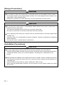
[Design Precautions]
WARNING
When controlling a running programmable controller (e.g. data modification), create an interlock
circuit on sequence programs so that the whole system functions safely all the time.
Also, be sure to read the manual carefully and ensure safety before performing any other controls
such as operating status change.
Especially, when controlling a programmable controller from a remote location via network, problems
on the programmable controller side may not be dealt with promptly due to failure of data
communications.
Create an interlock circuit on a sequence program.
For the operation status of each station at a communication error, refer to the manual for that station.
Incorrect output or malfunctions may cause an accident.
Install a safety circuit external to the programmable controller that keeps the entire system safe even
when there are problems with the external power supply or the programmable controller.
Otherwise, trouble could result from erroneous output or erroneous operation.
When the programmable controller system security needs to be protected against illegal access from
an external device via a network, take measures at the user's discretion.
A-1
[Design Precautions]
WARNING
Do not write any data to the "System area" in the buffer memory of the intelligent function module.
As for signals output from the programmable controller CPU to the intelligent function module, never
output (ON) a "Use prohibited" signal.
Doing these operations may cause malfunctions of the programmable controller system.
CAUTION
Do not bunch the control wires or communication cables with the main circuit or power wires, or
install them close to each other.
They should be installed 100 mm (3.94 inch) or more from each other.
Not doing so could result in noise that would cause erroneous operation.
During registering each setting, do not power OFF the mounted module or reset the programmable
controller CPU.
Otherwise, data in the CompactFlash card will be undefined. Therefore, resetting and re-registering
data are required.
This may also cause a module failure or malfunctions.
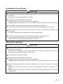
[Installation Precautions]
CAUTION
Use the programmable controller under the environment specified in the User's Manual.
Using this programmable controller in an environment outside the range of the general specifications
could result in electric shock, fire, erroneous operation, and damage to or deterioration of the
product.
While pressing the installation lever located at the bottom of module, insert the module fixing tab into
the fixing hole in the base unit until it stops.Then, securely mount the module with the fixing hole as a
supporting point.
Incorrect loading of the module can cause a malfunction, failure or drop.
When using the programmable controller in the environment of much vibration, tighten the module
with a screw.
A -2
[Installation Precautions]
CAUTION
Completely turn off the externally supplied power used in the system before mounting or removing
the module.
Not doing so could result in damage to the product.
Tighten the screw in the specified torque range.
Undertightening can cause a drop, short circuit or malfunction.
Overtightening can cause a drop, short circuit or malfunction due to damage to the screw or module.
Do not directly touch the module's conductive parts or electronic components.
Touching the conductive parts could cause an operation failure or give damage to the module.
When connecting a connector, properly press, crimp, or solder it using the tools specified by the
manufacturer.
Incomplete connection may cause short-circuit, fire, and malfunctions.
Push the CompactFlash card into the CompactFlash card slot and install it securely.
After installing the CompactFlash card, check that it is inserted securely.
Failure to do so may cause malfunctions due to poor contact.
[Wiring Precautions]
CAUTION
Always store the communication cables and power cables connected to the module in the duct or fix
them in place with clamps.
Not doing so may cause swing, move, or poor connection of the cable, or damage of a module and/
or cable due to careless pull, resulting in malfunctions.
Install connectors securely to modules.
Tighten the screw in the specified torque range.
Undertightening can cause a drop, short circuit or malfunction.
Overtightening can cause a drop, short circuit or malfunction due to damage to the screw or module.
When disconnecting communication cables connected to the module, never pull on the cable
section.
When using a cable with a connector, disconnect it with holding the connector connected to the
module.
When the cable is pulled while connected to the module, this may cause malfunctions or module/
cable damage.
A-3
[Wiring Precautions]
CAUTION
Be sure there are no foreign substances such as sawdust or wiring debris inside the module.
Such debris could cause fires, damage, or erroneous operation.
The module has an ingress prevention label on its top to prevent foreign matter, such as wire offcuts,
from entering the module during wiring.
Do not peel this label during wiring.
Before starting system operation, be sure to peel this label because of heat dissipation.
[Start-up and Maintenance Precautions]
WARNING
Do not touch any terminal during power distribution.
Doing so may cause malfunctions.
Always switch OFF the external supply power used by the system in all phases before cleaning or
retightening terminal screws.
Failure to do so may cause a failure or malfunctions of the module.
Loose screws may cause a drop of the module, short-circuit, or malfunctions.
Tightening screws excessively may damage the screws and/or the module, resulting in a drop of the
module, short-circuit, or malfunctions.
CAUTION
Do not disassemble or transform the module.
Doing so may cause a failure, malfunctions, personal injuries, and/or a fire.
Always shut OFF the external supply power used by the system in all phases before mounting or
removing a module.
Failure to do so may cause a failure or malfunctions of the module.
Do not install/remove the module to/from the base unit more than 50 times after the first use of the
product. (IEC 61131-2 compliant)
Failure to do so may cause malfunction.
Do not drop or apply any impact to the battery.
Doing so may damage the battery, resulting in a battery fluid leakage inside the battery.
If any impact has been applied, discard the battery and never use it.
Before handling a module, touch a grounded metal object to discharge the static electricity from the
human body.
Failure to do so may cause a failure or malfunctions of the module.
A -4
[Operation Precautions]
WARNING
Make sure safety before controlling a running programmable controller (e.g. data modification).
Do not write any data to the "System area" in the buffer memory of the intelligent function module.
As for signals output from the programmable controller CPU to the intelligent function module, never
output (ON) a "Use prohibited" signal.
Doing these operations may cause malfunctions of the programmable controller system.
[Disposal Precautions]
CAUTION
When disposing of the product, treat it as industrial waste.
When disposing of batteries, separate them from other wastes according to the local regulations.
(For details of the battery directive in EU member states, refer to Appendix 9.)
[Transportation Precautions]
CAUTION
When transporting lithium batteries, make sure to treat them based on the transportation regulations.
(Refer to Appendix 8 for details of the relevant models.)
A-5
CONDITIONS OF USE FOR THE PRODUCT
(1) Mitsubishi programmable controller ("the PRODUCT") shall be used in conditions;
i) where any problem, fault or failure occurring in the PRODUCT, if any, shall not lead to any major
or serious accident; and
ii) where the backup and fail-safe function are systematically or automatically provided outside of
the PRODUCT for the case of any problem, fault or failure occurring in the PRODUCT.
(2) The PRODUCT has been designed and manufactured for the purpose of being used in general
industries.
MITSUBISHI SHALL HAVE NO RESPONSIBILITY OR LIABILITY (INCLUDING, BUT NOT
LIMITED TO ANY AND ALL RESPONSIBILITY OR LIABILITY BASED ON CONTRACT,
WARRANTY, TORT, PRODUCT LIABILITY) FOR ANY INJURY OR DEATH TO PERSONS OR
LOSS OR DAMAGE TO PROPERTY CAUSED BY the PRODUCT THAT ARE OPERATED OR
USED IN APPLICATION NOT INTENDED OR EXCLUDED BY INSTRUCTIONS, PRECAUTIONS,
OR WARNING CONTAINED IN MITSUBISHI'S USER, INSTRUCTION AND/OR SAFETY
MANUALS, TECHNICAL BULLETINS AND GUIDELINES FOR the PRODUCT.
("Prohibited Application")
Prohibited Applications include, but not limited to, the use of the PRODUCT in;
• Nuclear Power Plants and any other power plants operated by Power companies, and/or any
other cases in which the public could be affected if any problem or fault occurs in the PRODUCT.
• Railway companies or Public service purposes, and/or any other cases in which establishment of
a special quality assurance system is required by the Purchaser or End User.
• Aircraft or Aerospace, Medical applications, Train equipment, transport equipment such as
Elevator and Escalator, Incineration and Fuel devices, Vehicles, Manned transportation,
Equipment for Recreation and Amusement, and Safety devices, handling of Nuclear or
Hazardous Materials or Chemicals, Mining and Drilling, and/or other applications where there is a
significant risk of injury to the public or property.
Notwithstanding the above, restrictions Mitsubishi may in its sole discretion, authorize use of the
PRODUCT in one or more of the Prohibited Applications, provided that the usage of the PRODUCT
is limited only for the specific applications agreed to by Mitsubishi and provided further that no
special quality assurance or fail-safe, redundant or other safety features which exceed the general
specifications of the PRODUCTs are required. For details, please contact the Mitsubishi
representative in your region.
A -6
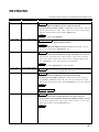
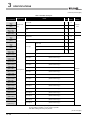
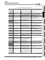
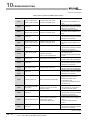
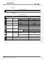
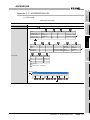
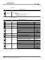
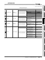
REVISIONS
The manual number is given on the bottom left of the back cover.
Print date
Manual number
Sep., 2006
SH(NA)-080644ENG-A
First edition
Revision
Jan., 2007
SH(NA)-080644ENG-B
Correction
GENERIC TERMS AND ABBREVIATIONS, DEFINITIONS AND
DESCRIPTIONS OF TERMS, Chapter 1, Sections 2.2, 2.4.2, 2.5, 3.1, 3.2, 3.5,
4.2, 4.6.2, 5.2, 6.1.10, 7.7.1, 7.8.1, 7.9.1, 7.10.1, 7.11.1, 7.11.2, 7.12.5, 7.13.2,
7.13.4, 8.1, 8.2, 8.6, 10.2.1, 10.3.2, 10.3.3, Appendix 3.9
Addition
Sections 2.6, 2.6.1, 2.6.2, Appendix 1
Apr., 2007
SH(NA)-080644ENG-C
Change of a term
"PLC" was changed to "programmable controller".
Correction
GENERIC TERMS AND ABBREVIATIONS, Sections 2.2, 2.5, 3.2, 7.7, 7.7.1,
7.8.1, 7.11.1, 7.12.2, 10.2.1, Appendices 2, 4.6
Oct., 2007
SH(NA)-080644ENG-D
Correction
DEFINITIONS AND DESCRIPTIONS OF TERMS, PACKING LIST, Sections 2.2,
2.4.2, 2.6.2, 3.1, 3.3, 3.6.10, 4.1, 6.1.6, 6.1.9, 7.3.1, 7.4.5, 7.6.2, 7.6.4, 7.8.1,
7.8.3, 7.9.1, 7.10.1 to 7.10.3, 7.10.5, 7.11.1, 7.11.2, 7.12.5, 8.5, 8.8.1, 8.8.2,
10.2.1, Appendices 1.1, 3.1, 3.2, 3.8, 3.10, 3.13, 3.15, 3.16
Addition
Sections 6.3.2, 7.8.2, Appendices 1.2, 3.5, 3.19, 3.20
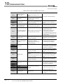
Oct., 2007
SH(NA)-080644ENG-E
Jan., 2008
SH(NA)-080644ENG-F
Correction
Sections 3.3, 7.8, 7.11.1, 7.12.5, Appendices 3.8, 3.20
Correction
GENERIC TERMS AND ABBREVIATIONS, DEFINITIONS AND
DESCRIPTIONS OF TERMS, Sections 1.1, 2.2 to 2.4, 2.6.2, 3.1, 3.2, 4.4.1,
4.7.1, Chapter 5, Sections 6.1.9, 6.1.10, 7.2, 7.3.1, 7.3.4, 7.5 to 7.11, 7.12.5,
7.13.4, 8.1 to 8.3, 8.5, 10.2.1, 10.2.2, 10.3.3, Appendices 1.1, 3.3, 3.4, 3.6 to 3.13
Addition
Appendix 7
Chenge of section No.
Appendix 7
Sep., 2008
SH(NA)-080644ENG-G
Appendix 8
Correction
SAFETY PRECAUTIONS, COMPLIANCE WITH THE EMC AND LOW
VOLTAGE DIRECTIVES, GENERIC TERMS AND ABBREVIATIONS, Sections
2.1.1, 2.2, 2.4.1, 2.4.2, 2.5, 3.1, 3.2, 4.1, 4.7.2, 4.8.1, 5.1, 6.1.4, 7.11.1, 7.11.2,
8.2, 8.5, 10.1.3, 10.2.1, 10.3.3, Appendices 1.1, 4
Addition
Appendix 9
A-7
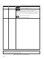
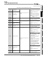
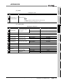
The manual number is given on the bottom left of the back cover.
Print date
Manual number
Revision
Jan., 2009
SH(NA)-080644ENG-H
Jan., 2010
SH(NA)-080644ENG-I
Correction
Sections 2.2, 3.2, 6.1.4, 10.3.3, Appendices 1.1, 1.2
Correction
SAFETY PRECAUTIONS, GENERIC TERMS AND ABBREVIATIONS,
DEFINITIONS AND DESCRIPTIONS OF TERMS, Sections 1.1, 2.3, 2.4.2, 2.5,
2.6.2, 3.1, 3.3, 4.3, 4.7.2, 4.8.1 to 4.8.3, 6.1.6, 6.1.9, 7.3.1, 7.3.4, 7.8.1, 7.9,
7.9.1, 7.10, 7.10.1, 7.11, 7.11.1, 7.12.5, 8.1, 8.2, 8.8.1, 10.2.1, 10.2.2, 10.3.2,
10.3.3,
Appendices 3.1, 3.10, 3.13 to 3.15, 3.19, 5, 7.1
Addition
CONDITIONS OF USE FOR THE PRODUCT
Japanese Manual Version SH-080643-H
This manual confers no industrial property rights or any rights of any other kind, nor does it confer any patent licenses.
Mitsubishi Electric Corporation cannot be held responsible for any problems involving industrial property rights which may
occur as a result of using the contents noted in this manual.
2006 MITSUBISHI ELECTRIC CORPORATION
A -8
INTRODUCTION
Thank you for choosing the Mitsubishi MELSEC-Q Series of General Purpose Programmable Controllers.
Before using the equipment, please read this manual carefully to develop full familiarity with the functions
and performance of the Q series programmable controller you have purchased, so as to ensure correct use.
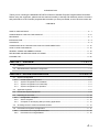
CONTENTS
SAFETY PRECAUTIONS .................................................................................................................................A - 1
CONDITIONS OF USE FOR THE PRODUCT..................................................................................................A - 6
REVISIONS.......................................................................................................................................................A - 7
INTRODUCTION...............................................................................................................................................A - 9
CONTENTS ......................................................................................................................................................A - 9
COMPLIANCE WITH THE EMC AND LOW VOLTAGE DIRECTIVES.......................................................... A - 15
HOW TO USE THIS MANUAL....................................................................................................................... A - 16
GENERIC TERMS AND ABBREVIATIONS................................................................................................... A - 18
DEFINITIONS AND DESCRIPTIONS OF TERMS ........................................................................................ A - 20
PACKING LIST .............................................................................................................................................. A - 22
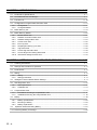
CHAPTER 1
OVERVIEW
1 - 1 to 1 - 8
1.1
Features........................................................................................................................................... 1 - 2
1.2
MX MESInterface Software Configuration ....................................................................................... 1 - 8
CHAPTER 2
2.1
SYSTEM CONFIGURATION
2 - 1 to 2 - 19
System Configuration ...................................................................................................................... 2 - 1
2.1.1
2.1.2
2.1.3
2.1.4
Overall system configuration .................................................................................................... 2 - 1
System configuration for installation......................................................................................... 2 - 2
System configuration for initial setup........................................................................................ 2 - 3
System configuration for operation........................................................................................... 2 - 4
2.2
Applicable Systems ......................................................................................................................... 2 - 5
2.3
Connection System Equipment ....................................................................................................... 2 - 8
2.4
Operating Environment.................................................................................................................. 2 - 10
2.4.1
2.4.2
2.4.3
Configuration computer .......................................................................................................... 2 - 10
Server computer ..................................................................................................................... 2 - 12
Computer for developing XML processing applications ......................................................... 2 - 13
2.5
Checking Function Version and Serial Number............................................................................. 2 - 14
2.6
Precautions for System Configuration ........................................................................................... 2 - 17
2.6.1
2.6.2
Precautions for using Redundant CPU................................................................................... 2 - 17
Precautions for using database .............................................................................................. 2 - 18
A-9
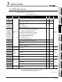
CHAPTER 3
SPECIFICATIONS
3 - 1 to 3 - 35
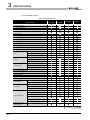
3.1
Performance Specifications ............................................................................................................. 3 - 1
3.2
Accessible Devices and Ranges ..................................................................................................... 3 - 5
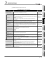
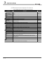
3.3
Function List .................................................................................................................................. 3 - 10
3.4
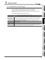
I/O Signals for Programmable Controller CPU .............................................................................. 3 - 14
3.4.1
3.4.2
I/O signal list ........................................................................................................................... 3 - 14
I/O signals details ................................................................................................................... 3 - 16
3.5
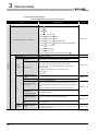
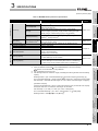
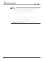
Buffer Memory List......................................................................................................................... 3 - 19
3.6
Buffer Memory Details ................................................................................................................... 3 - 24
3.6.1
3.6.2
3.6.3
3.6.4
3.6.5
3.6.6
3.6.7
3.6.8
3.6.9
3.6.10
CHAPTER 4
Module status area ................................................................................................................. 3 - 24
Network connection status area ............................................................................................. 3 - 24
Network settings status area .................................................................................................. 3 - 24
Current error area ................................................................................................................... 3 - 25
Error log area.......................................................................................................................... 3 - 26
Sampling/monitoring cycle area.............................................................................................. 3 - 28
Tag status area....................................................................................................................... 3 - 28
Current tag data value area .................................................................................................... 3 - 30
Access target CPU setting status area ................................................................................... 3 - 33
Information linkage function area............................................................................................ 3 - 34
SETTINGS AND PROCEDURE TO OPERATION
4 - 1 to 4 - 25
4.1
Handling Precautions....................................................................................................................... 4 - 1
4.2
Settings and Procedure to Operation .............................................................................................. 4 - 2
4.3
Parts Names .................................................................................................................................... 4 - 6
4.4
Wiring............................................................................................................................................... 4 - 8
4.4.1
4.4.2
Wiring........................................................................................................................................ 4 - 8
Wiring precautions .................................................................................................................... 4 - 8
4.5
Intelligent Function Module Switch Settings .................................................................................... 4 - 9
4.6
Self-diagnostics Test ..................................................................................................................... 4 - 12
4.6.1
4.6.2
4.7
CompactFlash Card ....................................................................................................................... 4 - 14
4.7.1
4.7.2
4.8
Precautions for using a CompactFlash card........................................................................... 4 - 14
Installation/removing the CompactFlash card......................................................................... 4 - 15
Battery ........................................................................................................................................... 4 - 20
4.8.1
4.8.2
4.8.3
4.9
Self-loopback test ................................................................................................................... 4 - 12
Hardware test ......................................................................................................................... 4 - 13
Battery specifications.............................................................................................................. 4 - 20
Mounting of battery ................................................................................................................. 4 - 20
Battery replacement................................................................................................................ 4 - 21
Operation without Mounting Battery ............................................................................................. 4 - 24
4.10 Removing Battery for Storage ....................................................................................................... 4 - 25
A - 10
CHAPTER 5
INSTALLATION AND UNINSTALLATION
5 - 1 to 5 - 9
5.1
Installation........................................................................................................................................ 5 - 1
5.2
Uninstallation ................................................................................................................................... 5 - 7
CHAPTER 6
6.1
FUNCTIONS
6 - 1 to 6 - 25
DB Interface Function ...................................................................................................................... 6 - 1
6.1.1
6.1.2
6.1.3
6.1.4
6.1.5
6.1.6
6.1.7
6.1.8
6.1.9
6.1.10
DB interface function operation ................................................................................................ 6 - 1
Job execution procedure .......................................................................................................... 6 - 2
Tag function.............................................................................................................................. 6 - 4
Trigger monitoring function....................................................................................................... 6 - 5
Trigger buffering function.......................................................................................................... 6 - 7
SQL text transmission (Communication action) ..................................................................... 6 - 10
Arithmetic processing function (Operation action) .................................................................. 6 - 11
Program execution function.................................................................................................... 6 - 11
DB buffering function .............................................................................................................. 6 - 12
Precautions............................................................................................................................. 6 - 21
6.2
XML Processing Function.............................................................................................................. 6 - 23
6.3
Time Synchronization Function ..................................................................................................... 6 - 24
6.3.1
6.3.2
Using the SNTP time query result in the programmable controller CPU ................................ 6 - 24
Daylight saving time function.................................................................................................. 6 - 25
CHAPTER 7
MES INTERFACE FUNCTION CONFIGURATION TOOL
7 - 1 to 7 - 135
7.1
MES Interface Function Configuration Tool..................................................................................... 7 - 1
7.2
Starting the MES Interface Function Configuration Tool ................................................................. 7 - 1
7.3
Screen Structure.............................................................................................................................. 7 - 2
7.3.1
7.3.2
7.3.3
7.3.4
7.4
Screen structure ....................................................................................................................... 7 - 2
Menu configuration ................................................................................................................... 7 - 4
Toolbar configuration................................................................................................................ 7 - 6
Operations using the Edit items tree ........................................................................................ 7 - 7
Project File Handling........................................................................................................................ 7 - 9
7.4.1
7.4.2
7.4.3
7.4.4
7.4.5
7.4.6
7.4.7
Creating a new project.............................................................................................................. 7 - 9
Opening a project ..................................................................................................................... 7 - 9
Saving a project...................................................................................................................... 7 - 10
Importing a project.................................................................................................................. 7 - 11
Importing a CSV file................................................................................................................ 7 - 13
Exporting a CSV file ............................................................................................................... 7 - 16
Printing a setting information file ............................................................................................ 7 - 16
7.5
Project Setting ............................................................................................................................... 7 - 17
7.6
System Setting............................................................................................................................... 7 - 18
7.6.1
7.6.2
7.6.3
7.6.4
7.7
Setting items in Network setting ............................................................................................. 7 - 19
Setting items in Time synchronization setting ........................................................................ 7 - 20
Setting items in Account setting ............................................................................................. 7 - 24
Setting items in DB buffering setting ...................................................................................... 7 - 27
Access Target CPU Setting ........................................................................................................... 7 - 32
7.7.1
Setting items in Access target CPU setting ............................................................................ 7 - 33
A - 11
7.8
Device Tag Setting ........................................................................................................................ 7 - 36
7.8.1
7.8.2
7.8.3
7.9
Setting items in Device Tag setting ........................................................................................ 7 - 37
Setting items in Array setting .................................................................................................. 7 - 41
Setting items in Component setting ........................................................................................ 7 - 43
Server Service Setting ................................................................................................................... 7 - 50
7.9.1
Setting items in Server Service setting ................................................................................... 7 - 51
7.10 Job Setting..................................................................................................................................... 7 - 55
7.10.1
7.10.2
7.10.3
7.10.4
7.10.5
Setting items in Job setting..................................................................................................... 7 - 56
Setting items in Trigger conditions.......................................................................................... 7 - 59
Setting items in Program execution ........................................................................................ 7 - 72
Setting items in DB Buffering.................................................................................................. 7 - 76
Setting items for job cancellation ............................................................................................ 7 - 77
7.11 Job Setting - Actions ...................................................................................................................... 7 - 78
7.11.1
7.11.2
Setting items in Communication action................................................................................... 7 - 82
Setting items in Operation action.......................................................................................... 7 - 108
7.12 Online .......................................................................................................................................... 7 - 112
7.12.1
7.12.2
7.12.3
7.12.4
7.12.5
7.12.6
Setting the target MES interface module .............................................................................. 7 - 112
Writing the MES interface function settings .......................................................................... 7 - 113
Reading the MES interface function settings........................................................................ 7 - 115
Verifying the MES interface function settings ....................................................................... 7 - 115
Checking the working log of the MES interface module ....................................................... 7 - 116
Executing a job as a one-shot task....................................................................................... 7 - 122
7.13 Online - Remote operation........................................................................................................... 7 - 123
7.13.1
7.13.2
7.13.3
7.13.4
7.13.5
7.13.6
7.13.7
7.13.8
Checking the operation status of the MES interface function ............................................... 7 - 124
Manipulating the operation status of the MES interface function.......................................... 7 - 125
Checking the connection of the previous job execution........................................................ 7 - 127
Changing the job status ........................................................................................................ 7 - 128
Checking the operation status of DB buffering ..................................................................... 7 - 129
Operating the DB buffering ................................................................................................... 7 - 130
Checking the operation status of the trigger buffering .......................................................... 7 - 131
Formatting the CompactFlash card ...................................................................................... 7 - 131
7.14 Help ............................................................................................................................................. 7 - 132
7.15 Precautions .................................................................................................................................. 7 - 133
CHAPTER 8
DB CONNECTION SERVICE AND SETTING TOOL
8 - 1 to 8 - 28
8.1
DB Connection Service Functions ................................................................................................... 8 - 1
8.2
Setting ODBC to the Database........................................................................................................ 8 - 5
8.3
Starting DB Connection Service Setting Tool ................................................................................ 8 - 12
8.4
Screen Structure of DB Connection Service Setting Tool ............................................................. 8 - 13
8.4.1
8.4.2
Screen structure ..................................................................................................................... 8 - 13
Menu configuration ................................................................................................................. 8 - 14
8.5
Setting Items of DB Connection Service Setting Tool ................................................................... 8 - 15
8.6
Importing/Exporting Files .............................................................................................................. 8 - 20
8.7
Help ............................................................................................................................................... 8 - 22
A - 12
8.8
Output Log Specifications.............................................................................................................. 8 - 23
8.8.1
8.8.2
Access log .............................................................................................................................. 8 - 24
SQL failure log........................................................................................................................ 8 - 28
CHAPTER 9
XML MESSAGE FORMAT
9 - 1 to 9 - 6
9.1
XML Message Format Definition ..................................................................................................... 9 - 2
9.2
XML Message Format Sending Method .......................................................................................... 9 - 4
9.2.1
9.2.2
XML message format sending method..................................................................................... 9 - 4
Sample program ....................................................................................................................... 9 - 5
CHAPTER 10
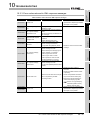
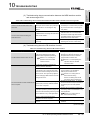
10.1
Finding an error code ............................................................................................................. 10 - 2
Error types .............................................................................................................................. 10 - 3
System monitor....................................................................................................................... 10 - 4
Error Code List............................................................................................................................... 10 - 7
10.2.1
10.2.2
10.2.3
10.3
10 - 1 to 10 - 46
Error Codes ................................................................................................................................... 10 - 2
10.1.1
10.1.2
10.1.3
10.2
TROUBLESHOOTING
Error codes for the MES interface module ............................................................................. 10 - 7
Error codes of DB Connection Service................................................................................. 10 - 22
Error codes returned in XML response messages ............................................................... 10 - 32
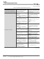
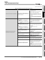
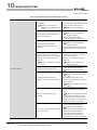
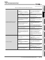
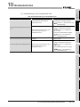
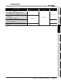
Troubleshooting by symptom....................................................................................................... 10 - 33
10.3.1
10.3.2
10.3.3
When using MES Interface Function Configuration Tool...................................................... 10 - 33
When using DB Connection Service Setting Tool ................................................................ 10 - 38
When operating the MES interface module.......................................................................... 10 - 39
APPENDICES
App - 1 to App - 67
Appendix 1 Functions Added in MES Interface Module and MX MESInterface .....................................App - 1
Appendix 1.1 Addition of new functions ............................................................................................App - 1
Appendix 1.2 Operations of former versions ..................................................................................... App - 3
Appendix 2 Usable Characters and ASCII Code Tables ........................................................................ App - 5
Appendix 2.1 ASCII code table .........................................................................................................App - 5
Appendix 2.2 Characters available for item names, component names, variable names, etc. .........App - 6
Appendix 2.3 Characters available for character string constants, etc. ............................................App - 7
Appendix 2.4 Characters available for field names, table names, etc............................................... App - 7
Appendix 3 Setting Information File Format (CSV File Format) .............................................................App - 8
Appendix 3.1
Appendix 3.2
Appendix 3.3
Appendix 3.4
Appendix 3.5
Appendix 3.6
Appendix 3.7
Appendix 3.8
Appendix 3.9
Appendix 3.10
Appendix 3.11
Appendix 3.12
Appendix 3.13
Setting information files list..........................................................................................App - 8
Setting information file format and editing precautions ...............................................App - 9
SYSTEM.CSV ...........................................................................................................App - 12
ACCOUNT.CSV ........................................................................................................App - 14
DST.CSV................................................................................................................... App - 16
DBBUF.CSV..............................................................................................................App - 18
CPU.CSV ..................................................................................................................App - 19
TAG.CSV................................................................................................................... App - 22
COMPONENT.CSV...................................................................................................App - 24
SERVER.CSV ...........................................................................................................App - 26
JOB.CSV ................................................................................................................... App - 28
CONDITION.CSV...................................................................................................... App - 30
ACTION.CSV ............................................................................................................App - 34
A - 13
Appendix 3.14 ACFIELD.CSV ...........................................................................................................App - 36
Appendix 3.15 ACCONDITION.CSV .................................................................................................App - 38
Appendix 3.16 ACEXCEPTION.CSV ................................................................................................App - 40
Appendix 3.17 ACOPERATION.CSV ................................................................................................App - 42
Appendix 3.18 REMOTE.CSV...........................................................................................................App - 45
Appendix 3.19 ORDERBY.CSV ........................................................................................................App - 47
Appendix 3.20 MULTISELECT.CSV .................................................................................................App - 48
Appendix 4 Processing Time ................................................................................................................App - 50
Appendix 4.1 Product whose first five digits of serial No. is "09102" or later ..................................App - 50
Appendix 4.2 Product whose first five digits of serial No. is "09101" or earlier ...............................App - 53
Appendix 5 External Dimensions..........................................................................................................App - 55
Appendix 6 Data Collection Method for CPUs that cannot be Accessed Directly ................................App - 56
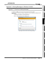
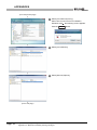
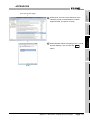
Appendix 7 Warning Messages in Windows Vista(R)...........................................................................App - 58
Appendix 7.1 Overview of warning messages.................................................................................App - 58
Appendix 7.2 Methods for disabling warning messages .................................................................App - 59
Appendix 8 Transportation Precautions................................................................................................App - 65
Appendix 8.1 Controlled model .......................................................................................................App - 65
Appendix 8.2 Handling for shipping.................................................................................................App - 65
Appendix 9 Handling of Batteries and Devices with Built-in Batteries in EU Member States...............App - 66
Appendix 9.1 Disposal precautions .................................................................................................App - 66
Appendix 9.2 Exportation precautions.............................................................................................App - 67
INDEX
A - 14
Index - 1 to Index - 2
COMPLIANCE WITH THE EMC AND LOW VOLTAGE DIRECTIVES
(1) For programmable controller system
To configure a system meeting the requirements of the EMC and Low Voltage
Directives when incorporating the Mitsubishi programmable controller (EMC and Low
Voltage Directives compliant) into other machinery or equipment, refer to
Chapter 9 "EMC AND LOW VOLTAGE DIRECTIVES" of the QCPU User's Manual
(Hardware Design, Maintenance and Inspection).
The CE mark, indicating compliance with the EMC and Low Voltage Directives, is
printed on the rating plate of the programmable controller.
(2) For the product
For the compliance of this product with the EMC and Low Voltage Directives, refer to
Section 9.1.3 "Cables" in Chapter 9 "EMC AND LOW VOLTAGE DIRECTIVES" of the
QCPU User's Manual (Hardware Design, Maintenance and Inspection).
A - 15
HOW TO USE THIS MANUAL
This manual is organized by objective for using the QJ71MES96 MES interface module
and MX MESInterface Version1 (SW1DNC-MESIF-E). Use this manual with referring to
the following.
(1) Features and software configuration
Chapter 1 OVERVIEW
Section 1.1 covers the features.
Section 1.2 covers the MX MESInterface software configuration.
(2) System configuration, applicable systems, connection system equipment, and
operating environment
Chapter 2 SYSTEM CONFIGURATION
Section 2.1 covers the system configuration.
Section 2.2 covers the applicable systems.
Section 2.3 covers the connection system equipment.
Section 2.4 covers the operating environment.
(3) Performance specifications about the MES interface module
Chapter 3 SPECIFICATIONS
Section 3.1 covers the performance specifications.
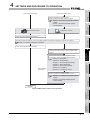
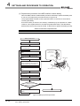
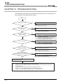
(4) Procedure up to MES interface Function module start-up
Chapter 4 SETTINGS AND PROCEDURE TO OPERATION
Section 4.2 covers the schematic procedure up to the MES interface module operation.
(5) Installation and uninstallation methods for MX MESInterface
Chapter 5 INSTALLATION AND UNINSTALLATION
Chapter 5 covers MX MESInterface installation and uninstallation methods.
(6) MES interface module functions
Chapter 6 FUNCTIONS
Chapter 6 covers the MES interface module functions.
(7) Setting method for MES Interface Function Configuration Tool
Chapter 7 MES INTERFACE FUNCTION CONFIGURATION TOOL
Chapter 7 covers the setting method of the MES Interface Function Configuration
Tool.
(8) Setting method for DB Connection Service
Chapter 8 DB CONNECTION SERVICE AND SETTING TOOL
Chapter 8 covers the functions and setting method for the DB Connection Service.
(9) XML message format
Chapter 9 XML MESSAGE FORMAT
Chapter 9 covers the XML message format.
(10)Methods for checking errors and the corrective actions
Chapter 10 TROUBLESHOOTING
Chapter 10 covers troubleshooting and lists the error codes.
A - 16
Displaying a reference
Reference in this manual and
reference manual are shown
with
.
Displaying a chapter title
Index on the right of a page
clears the chapter of the page.
Displaying a section title
The section in which the open page
is included is clear.
The above is different from the actual page, as it is provided for explanation only.
In addition, this manual provides the following explanations.
Explains the matters to be especially noted, the functions and others related to the
description on that page.
Remark
Provides the reference destination related to the description on that page and the
convenient information.
A - 17
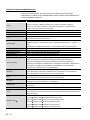
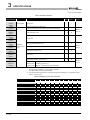
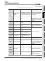
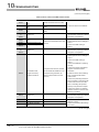
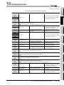
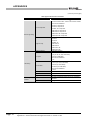
GENERIC TERMS AND ABBREVIATIONS
Unless otherwise specified, this manual uses the following generic terms and
abbreviations to explain the QJ71MES96 MES interface module and MX MESInterface
Version1 (SW1DNC-MESIF-E).
Generic term/abbreviation
Description
Generic term for the A1NCPU, A0J2HCPU, A1SCPU, A1SHCPU, A1SJCPU, A1SJHCPU,
ACPU
A2CCPU, A2CJCPU, A2NCPU, A2NCPU-S1, A2SCPU, A2SHCPU, A2ACPU,
A2ACPU-S1, A2UCPU, A2UCPU-S1, A2USCPU, A2USCPU-S1, A2USHCPU-S1,
CC-Link
A3NCPU, A3ACPU, A3UCPU, and A4UCPU
Abbreviation for CC-Link system
Ethernet
Ethernet module
Generic term for 100BASE-TX, 10BASE-T, 10BASE5, and 10BASE2 network systems
Generic term for the E71, QE71, and Q series E71
E71
Generic term for the AJ71E71N3-T, AJ71E71N-B5, AJ71E71N-B2, A1SJ71E71N3-T,
A1SJ71E71N-B5, and A1SJ71E71N-B2
Generic product name for the model names of the SWnD5C-GPPW-E,
GX Developer
SWnD5C-GPPW-EA, SWnD5C-GPPW-EV, and SWnD5C-GPPW-EVA. (n = Version 4 or
later)
MELSECNET/H
- A designates a multiple-license product; -V designates a version upgraded product.
Abbreviation for MELSECNET/H network system supporting the Q series
MELSECNET/10
MES interface module
Abbreviation for MELSECNET/10 network system supporting the AnU and QnA/Q4AR
Abbreviation for the QJ71MES96 MES interface module
MX MESInterface
QCPU (A mode)
Product name for the model name SW1DNC-MESIF-E
Generic term for the Q02CPU-A, Q02HCPU-A, and Q06HCPU-A
Generic term for the Q00JCPU, Q00CPU, Q01CPU, Q02CPU, Q02HCPU, Q06HCPU,
Q12HCPU, Q25HCPU, Q02PHCPU, Q06PHCPU, Q12PHCPU, Q25PHCPU,
QCPU (Q mode)
Q12PRHCPU, Q25PRHCPU, Q00UJCPU, Q00UCPU, Q01UCPU, Q02UCPU,
Q03UDCPU, Q04UDHCPU, Q06UDHCPU, Q10UDHCPU, Q13UDHCPU, Q20UDHCPU,
Q26UDHCPU, Q03UDECPU, Q04UDEHCPU, Q06UDEHCPU, Q10UDEHCPU,
Q13UDEHCPU, Q20UDEHCPU, and Q26UDEHCPU
Generic term for the AJ71QC24, AJ71QC24-R2, AJ71QC24-R4, A1SJ71QC24,
QC24(N)
A1SJ71QC24-R2, AJ71QC24N, AJ71QC24N-R2, AJ71QC24N-R4, A1SJ71QC24N,
A1SJ71QC24N-R2, A1SJ71QC24N1, and A1SJ71QC24N1-R2
QE71
QnACPU
Q series C24
Q series E71
Generic term for the AJ71QE71N3-T, AJ71QE71N-B5, AJ71QE71N-B2,
A1SJ71QE71N3-T, A1SJ71QE71N-B5, and A1SJ71QE71N-B2
Generic term for the Q2ACPU, Q2ACPU-S1, Q2ASCPU, Q2ASCPU-S1, Q2ASHCPU,
Q2ASHCPU-S1, Q3ACPU, Q4ACPU, and Q4ARCPU
Generic term for the QJ71C24N, QJ71C24N-R2, QJ71C24N-R4, QJ71C24, and
QJ71C24-R2
Generic term for the QJ71E71-100, QJ71E71-B5, and QJ71E71-B2
Generic term for the AJ71UC24, A1SJ71UC24-R2, A1SJ71UC24-R4, A1SJ71UC24-PRF,
UC24
A1SJ71C24-R2, A1SJ71C24-R4, A1SJ71C24-PRF, A1SCPUC24-R2, A2CCPUC24, and
A2CCPUC24-PRF
Generic term for the following:
Windows Vista
Microsoft Windows Vista
Home Basic Operating System
Microsoft Windows Vista
Home Premium Operating System
Microsoft Windows Vista
Business Operating System
Microsoft Windows Vista
Ultimate Operating System
Microsoft Windows Vista
Enterprise Operating System
(To the next page)
A - 18
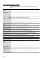
(From the previous page)
Generic term/abbreviation
Description
Generic term for the following:
Windows XP
Computer link module (Serial
communication module)
Personal computer
Microsoft Windows XP Professional Operating System
Microsoft Windows XP Home Edition Operating System
Generic term for the UC24, QC24(N), and Q series C24
Especially when referring to the QC24(N) and Q series C24, they are written as "Serial
communication module".
Abbreviation for the IBM-PC/AT-compatible personal computer
A - 19
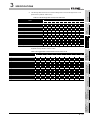
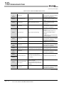
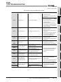
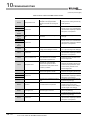
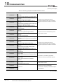
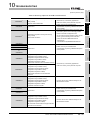
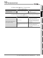
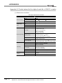
DEFINITIONS AND DESCRIPTIONS OF TERMS
The following table shows the definitions and descriptions of the terms used in this
manual.
Term
CSV
DB buffering
Description
Abbreviation for Comma Separated Values
Text file in which the data are aligned and set off by commas and double quotations
Function temporarily stores SQL text that failed to be sent due to a communication error and
resends the text when the communications have been recovered
Abbreviation for Hyper Text Transfer Protocol
HTTP
Protocol to exchange XML format messages between the MES interface module and user
applications in the XML processing function
Tag for Wonderware
Historian
Name for data unit in the data base Wonderware
Historian.
Abbreviation for Manufacturing Execution Systems
Systems for controlling and monitoring the plant status in real time to optimize production
MES
activities
The systems enable to speed up the responses to production plan and status changes that lead
to efficient production processes and optimization of production activities.
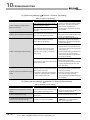
ODBC
SNTP
SNTP server computer
SQL
URL
URL encode
XML
Item
Account
Abbreviation for Open DataBase Connectivity
Standard specifications for software to access databases
Abbreviation for Simple Network Time Protocol
Protocol for synchronizing computer time via a TCP/IP network
Computer that provides time information to the MES interface module
This computer can be shared with a server computer.
Abbreviation for Structured Query Language
Data manipulation language and used for relational database operations
Abbreviation for Uniform Resource Locator
Notation method for indicating the locations of information resources on the Internet
Converts character strings into characters can be used in URLs.
This designates percent encoding defined by RFC3986.
Abbreviation for eXtensible Markup Language
Markup language for describing documentation, data meanings, and structures
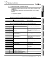
One setting group unit included each setting type for editing
Designates the right to use the MES interface module or server computer, or an ID necessary for
their use.
Unit for processing defined in a job
There are [Communication action] for communicating with a database and [Operation action] for
Action
operating tag component values.
[Communication action] is a processing unit for sending one SQL text (Select, Update, Insert,
MultiSelect, or Delete).
[Operation action] is a processing unit of up to 20 dyadic operations.
System switching
Function for the Redundant CPU to switch between control system and standby system of the
redundant system. (Switching from control system to standby system, and vice versa.)
COMMIT
Processing for finalizing the changes to a database
Storage card regulated by the [CF+ and CompactFlash Specification] issued by the Compact
CompactFlash card
Flash Association
(CF card)
This memory card is necessary for the MES interface module to operate the MES interface
function.
(To the next page)
A - 20
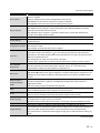
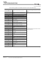
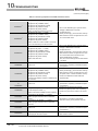
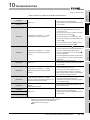
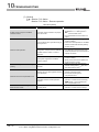
(From the previous page)
Term
Description
Generic term for the services can be offered by a server computer to which DB Connection
Service is installed
Server service
There are database server service and application server service.
The database server service is a service for accessing a database.
The application server service is a service for linking with a program.
There are database server computers and application server computers.
The database server computer is a personal computer with a relational database which links
Server computer
information with the MES interface module.
The application server computer is a personal computer with a program that operates upon
request from the MES interface module.
Job
Update settings
Configuration computer
Unit for accessing a database
Processing updates the MES interface module settings from MES Interface Function
Configuration Tool
Personal computer for configuring various settings required for the MES interface function in the
MES interface module
This computer can be shared with a server computer.
Standard time zone for each region of the world
Each nation uses the time difference ( 12 hours maximum) from the time at the Greenwich
Time zone
Observatory in the United Kingdom (GMT) as the standard time. The region using the same time
difference is called a time zone.
The standard time for Japan is 9 hours ahead of the GMT.
Tag component
(Component)
Data source
In some nations, daylight time in which the clock is advanced for one hour is used in summer.
Generic term for a component (Device data) making up a device tag (Tag)
This data organizes the communications path, data type, device, etc. for access to each
programmable controller CPU device data as a single data unit.
Connection information necessary for accessing data using ODBC
With Windows , a data source name is assigned to connection information for management. The
database can be accessed via ODBC by specifying the data source name in the MES interface
function.
Database (DB) or
relational database
(RDB)
Table
Device
Data management method that follows relational data model logic
One data is expressed as a collection of multiple items (Fields) and the data collection is
expressed as a table.
Data can be easily merged and selected using key data.
Data management format managed with relational databases
It is a two-dimensional table format composed of rows and columns.
Variety of memory data in the programmable controller
There are devices handled in units of bits and devices handled in units of words.
Data table that contains a set of information (Component) required to access the device data in
Device tag (Tag)
the programmable controller CPUs on the network
Trigger condition
Startup conditions for job operation
When trigger conditions (conditions for data transmission) of multiple jobs are met in a
The MES interface module collects device data in units of tags at an interval defined in the tag.
concentrated manner, their data and trigger times are buffered in the module's internal memory so
Trigger buffering
that actions (data operation/transmission) can be executed later using the buffered data.
Even if the frequency of data transmission triggers is high, jobs are executed without missing any
trigger.
(To the next page)
A - 21
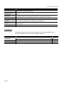
(From the previous page)
Term
Data separation
Description
New data and old data are mixedly exists in units of 16 bits (1 word) in 32 bits data (2 words) or
Daylight saving
larger data due to data reception timing.
The system in which clocks are set one hour ahead of standard time in a specific period of time in
(Summer time)
summer.
Handshake
For highly reliable processing, programmable controller CPU devices are used to manage
processing between the programmable controller CPU and MES interface module.
Field
Variable (Temporary
Corresponds to a column in a relational database and indicates a type of data (Record attribute).
Variable that can be used in a single job for temporary storage of values selected from a database
variable)
and for writing operation values to a database or tag components
Corresponds to a row in a relational database. One row (Record) stores the values of multiple
Record
columns (Fields).
Rollback
Processing for canceling changes to a database
PACKING LIST
The following table shows the products included to the QJ71MES96 MES interface
module and MX MESInterface Version1 (SW1DNC-MESIF-E).
Model
Product name
Quantity
QJ71MES96
QJ71MES96MES interface module
Battery (Q6BAT)
1
1
SW1DNC-MESIF-E
SW1DNC-MESIF-EA
MX MESInterface Version 1 (with one license)
(CD-ROM)
MX MESInterface Version 1 (with multiple licenses)
(CD-ROM)
1
1
A - 22
Memo
A - 23
1
OVERVIEW
CHAPTER 1 OVERVIEW
This manual explains the specifications, preparatory procedures, functions, and
troubleshooting for the MELSEC-Q series QJ71MES96 MES interface module (hereafter,
abbreviated as MES interface module).
When applying the following program examples to the actual system, make sure to
examine the applicability and confirm that it will not cause system control problems.
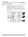
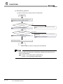
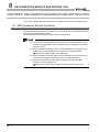
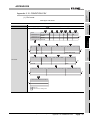
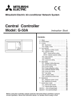
The MES interface module links the programmable controller (Production equipment)
device data with information system (Manufacturing Execution System) database without
communication gateways.
Information linkage using the MES interface module
Conventional information linkage
without the MES interface module
<Manufacturing Execution System>
<Manufacturing Execution System>
Information system
(Database)
Information system
(Database)
<Communication gateway>
Computerization via
communication gateways
is unnecessary.
Host information system
communication processing
SQL
XML
Data processing
(Operation processing,
logging, etc.)
Controller communication
<Production equipment>
<Production equipment>
MES interface module
Communication module
Programmable controller CPU
(Device data)
Programmable controller CPU
(Device data)
Figure 1.1 Information linkage using the MES interface module
1-1
OVERVIEW
1
(1) Connection with the information system is enabled by simple settings without
program
Access to information system databases can be realized simply by making the
necessary settings with the setting tool.
There is no need to write programs for accessing databases, so the engineering costs
for system construction can be reduced and the work period can be shortened.
2
SYSTEM
CONFIGURATION
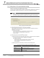
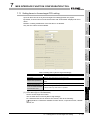
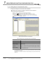
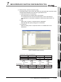
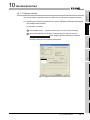
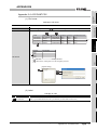
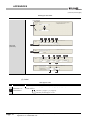
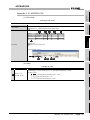
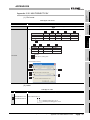
This section explains the features of MX MESInterface.
OVERVIEW
1.1 Features
3
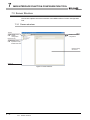
SPECIFICATIONS
[MX MESInterface] - [MES interface function configuration tool]
SETTINGS AND
PROCEDURE TO
OPERATION
4
INSTALLATION AND
UNINSTALLATION
5
Figure 1.2 [MX MESInterface] - [MES interface function configuration tool]
FUNCTIONS
6
MES INTERFACE
FUNCTION
CONFIGURATION TOOL
7
8
DB CONNECTION
SERVICE AND
SETTING TOOL
1
1.1 Features
1-2
1
OVERVIEW
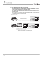
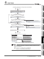
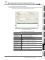
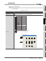
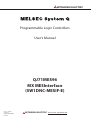
(2) The information system load can be reduced.
Data can be monitored on the MES interface module side and when the conditions
are met, the data can be sent to the information system.
Also, the data can be operated and the results of the operations can be sent to the
information system.
This can reduce the information system loads compared to the conventional system
of constantly obtaining and monitoring data.
[MES interface module...]
<Information system>
Sends data as required.
Conditions
met
Database
[In the conventional system...]
<Information system>
Database
Constantly obtaining/monitoring data
from information system are required.
Figure 1.3 Loads reduction of information system
1-3
1.1 Features
OVERVIEW
1
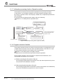
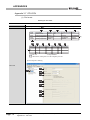
[MES interface module]
Trigger buffer
Job1-2) Trigger information (Tag data, time)
Job3-3) Trigger information (Tag data, time)
Job1-1)
Action
execution
Job 1-2)
Trigger conditions
met
Sending
data
Database
Executes action of Job 1-1), and
stores trigger information of Job 1-2)
and 3-3) in the trigger buffer.
Job3-3)
Trigger conditions
met
SETTINGS AND
PROCEDURE TO
OPERATION
Time
After loads have been reduced
[When loads are reduced]
Trigger buffer
Job 1-2)
Action
execution
Job3-3)
Action
execution
Time
4
Sending
data
5
Database
After completing the action of Job 1-1),
executes actions of Job 1-2) and 3-3)
in this order based on the trigger buffer
information.
Time
INSTALLATION AND
UNINSTALLATION
Time
SPECIFICATIONS
3
[When loads are concentrated]
Job1-1)
Trigger conditions
met
2
SYSTEM
CONFIGURATION
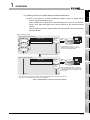
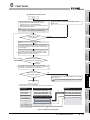
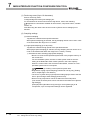
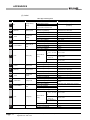
(a) Even if the frequency of data transmission triggers is high, no trigger will be
missed. (Trigger buffering function)
When multiple sets of conditions for data transmission are met in a concentrated
manner, their data and trigger times can be buffered in the module's internal
memory.
After the loads are reduced, data operations and transmission are executed using
the buffered data.
OVERVIEW
(3) Buffering function for reliable data acquisition/transmission
6
The numbers 1) to 3) show the order in which trigger conditions of respective jobs are met.
Job 1 and 3 are assumed to access the same database.
FUNCTIONS
Figure 1.4 Data buffering in the case of load concentration
MES INTERFACE
FUNCTION
CONFIGURATION TOOL
7
8
DB CONNECTION
SERVICE AND
SETTING TOOL
1
1.1 Features
1-4
1
OVERVIEW
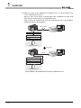
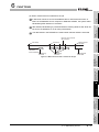
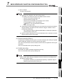
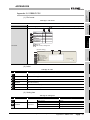
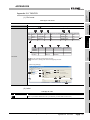
(b) Data to be send to the database are protected even if a communication error
occurs. (DB buffering function)
When an error occurs during communications with a database, the SQL texts
failed to send can be stored in a CompactFlash card.
After recovery, the buffered SQL texts are automatically sent to the database.
(Manual operation is also possible.)
Disconnected
Database
Insert...
Insert...
Insert...
Update...
CompactFlash card
Recovered
Resend
Database
Insert...
Insert...
Insert...
Update...
CompactFlash card
Figure 1.5 Buffering of send data (SQL text) during a communication error
1-5
1.1 Features
OVERVIEW
1
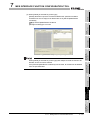
After connection with a database, when there is a communication error, a log of the
error contents can be recorded to the database side.
Analyzing the log can protect data and analyze the error.
OVERVIEW
(4) Log data are available in the event of an access error
SYSTEM
CONFIGURATION
2
Database
DB Connection
Service
SPECIFICATIONS
SQL
failure
log
(5) Directions from the information system can be realized.
Processing registered in the MES interface module can be started from information
system applications.
This enables to realize production directions from the information system.
Not only can data be sent to a database but it can also be received from a database.
This enables to download data such as production information from information
system databases.
1) Instructs job execution.
2) Starts registered
processing.
(Job execution)
6
1) Instructs job execution.
2) Starts registered
processing.
(Job execution)
Database
FUNCTIONS
3) Sends data.
<MES interface module>
<Information system>
5
<Information system>
7
MES INTERFACE
FUNCTION
CONFIGURATION TOOL
<MES interface module>
SETTINGS AND
PROCEDURE TO
OPERATION
4
Figure 1.6 Obtaining logs for access errors
INSTALLATION AND
UNINSTALLATION
Access
log
3
Database
3) Sends data.
Figure 1.7 Realization of directions from the information system
8
DB CONNECTION
SERVICE AND
SETTING TOOL
1
1.1 Features
1-6
1
OVERVIEW
(6) Supporting diverse databases
When designing a new system, a wide range of database types can be selected.
Even when connecting to the existing system, the system can be transferred without
changing the existing database.
(7) Access independent of the database table configuration is possible.
Freely designed database tables can be used for access to databases.
When designing a new system, not only the high flexibility of design, but when
connecting to the existing system, the system can be constructed without changing
the database tables.
(8) Time synchronization using SNTP is also possible.
The clocks for the MES interface module and the programmable controller CPU can
be set through communications with an SNTP server computer.
This enables to synchronize the time for the entire system.
1-7
1.1 Features
1
OVERVIEW
1
OVERVIEW
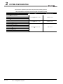
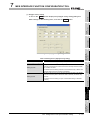
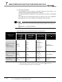
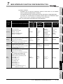
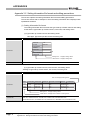
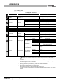
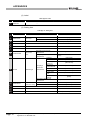
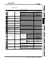
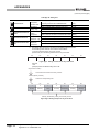
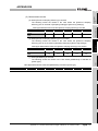
1.2 MX MESInterface Software Configuration
Table 1.1 MX MESInterface software configuration
Description
Reference
section
Installs each execution software (MES Interface Function Configuration Tool, DB
Installer
Connection Service, and DB Connection Service Setting Tool) in each operating
Chapter 5
environment.
Operates on a configuration computer and configures various settings required for the
MES Interface Function
MES interface function.
Configuration Tool
In addition to the configuration, the application tool offers features such as the operation
Chapter 7
status check, working log check, or stop/restart operation.
DB Connection Service
Operates on the server computer and links databases with the MES interface module.
DB Connection Service
Operates on the server computer and changes the settings of the DB Connection
Setting Tool
Service.
2
3
Chapter 8
Chapter 8
SPECIFICATIONS
Item
SYSTEM
CONFIGURATION
This section explains the MX MESInterface software configuration.
SETTINGS AND
PROCEDURE TO
OPERATION
4
INSTALLATION AND
UNINSTALLATION
5
FUNCTIONS
6
MES INTERFACE
FUNCTION
CONFIGURATION TOOL
7
DB CONNECTION
SERVICE AND
SETTING TOOL
8
1.2 MX MESInterface Software Configuration
1-8
2
SYSTEM CONFIGURATION
CHAPTER 2 SYSTEM CONFIGURATION
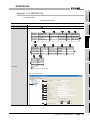
This chapter explains the system configuration of the MES interface module.
2.1 System Configuration
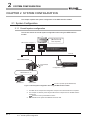
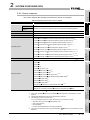
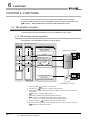
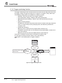
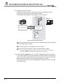
2.1.1 Overall system configuration
This section shows the overall system configuration when using the MES interface
module.
Oracle R , SQL Server R , etc.
(manufactured by
other companies)
Database
SNTP server computer *1 *2
Server computer *3
DB Connection Service
DB Connection Service Setting Tool
Ethernet
MES interface module
MES Interface Function
Configuration Tool
CompactFlash
card
Configuration computer *1
MELSECNET/H, etc.
Q/QnA/ACPU
Q/QnA/ACPU
:Functions provided by MX MESInterface
Figure 2.1 Overall system configuration when using the MES interface module
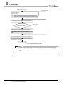
*1
*2
*3
2-1
The SNTP server computer and configuration computer can be shared with server computers.
This computer is necessary when using the SNTP server computer time for the MES interface
module time.
Section 6.3 Time Synchronization Function
The redundant server system and database cannot be used.
2.1 System Configuration
2.1.1 Overall system configuration
SYSTEM CONFIGURATION
1
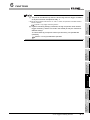
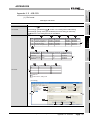
This section shows system configurations for installing MX MESInterface.
Server computer
MX MESInterface
2
SYSTEM
CONFIGURATION
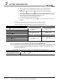
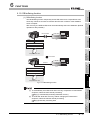
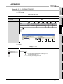
(1) When installing DB Connection Service and DB Connection Service Setting
Tool on a server computer
OVERVIEW
2.1.2 System configuration for installation
Installation
3
DB Connection Service
DB Connection Service Setting Tool
SPECIFICATIONS
Commercialized product
(1) When installing DB Connection Service on a database server computer, the
ODBC setting for the database used must be done beforehand.
Section 8.2 Setting ODBC to the Database
(2) When installing DB Connection Service on an application server computer, an
account for user program execution must be created beforehand.
4
SETTINGS AND
PROCEDURE TO
OPERATION
Figure 2.2 Installing DB Connection Service and DB Connection Service Setting Tool
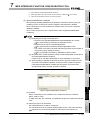
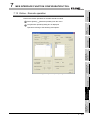
(2) When installing MES Interface Function Configuration Tool on a configuration
computer
Configuration computer
MX MESInterface
6
Installation
Commercialized product
FUNCTIONS
MES Interface Function
Configuration Tool
INSTALLATION AND
UNINSTALLATION
5
Figure 2.3 Installing MES Interface Function Configuration Tool
MES INTERFACE
FUNCTION
CONFIGURATION TOOL
7
8
DB CONNECTION
SERVICE AND
SETTING TOOL
2
2.1 System Configuration
2.1.2 System configuration for installation
2-2
2
SYSTEM CONFIGURATION
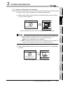
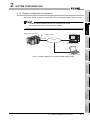
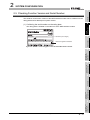
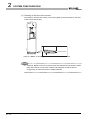
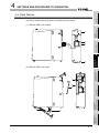
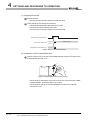
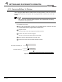
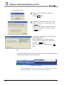
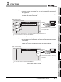
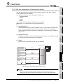
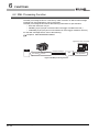
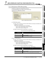
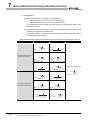
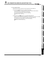
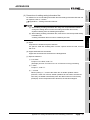
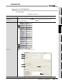
2.1.3 System configuration for initial setup
This section shows system configurations for initial setup of the MES interface module
using MES Interface Function Configuration Tool.
MES interface module
Twisted pair cable
(Crossing cable)
Ethernet
Configuration computer
or
MES interface module
Twisted pair cable
(Straight cable)
Ethernet
Hub
Configuration computer
Figure 2.4 System configurations for initial setup of the MES interface module
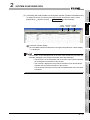
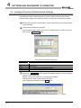
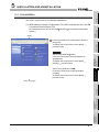
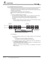
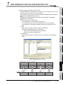
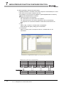
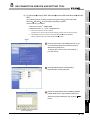
Remark
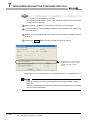
The following explains the network settings of the configuration computer when
connecting it to the MES interface module on a 1:1 basis.
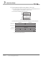
1 Set the same network address as the one of the MES interface module in the
network settings for the configuration computer.
Set the values to be identical.
Set different values.
Default value of
"MES interface module" Network section
Host
section
"Configuration computer"
Network section
Host
section
IP ADDRESS
192.168.3.
3
IP ADDRESS
192.168.3.
1
Subnet mask
255.255.255.
0
Subnet mask
255.255.255.
0
Figure 2.5 Network settings for configuration computer
2 Make the network settings of the configuration computer in the [Internet Protocol
(TCP/IP) Properties] dialog box.
Example: Microsoft Windows XP Professional Operating System
Figure 2.6 [Internet Protocol (TCP/IP) Properties] dialog box
3
2-3
2.1 System Configuration
2.1.3 System configuration for initial setup
SYSTEM CONFIGURATION
1
This section shows the system configuration when operating the MES interface module.
2
SYSTEM
CONFIGURATION
The MES interface module can only be connected with a LAN.
The module cannot be connected via the Internet.
MES interface module
OVERVIEW
2.1.4 System configuration for operation
Twisted pair cable
3
Intranet
SPECIFICATIONS
Ethernet
Server computer
SNTP server computer
Configuration computer
Figure 2.7 System configuration for operating the MES interface module
SETTINGS AND
PROCEDURE TO
OPERATION
4
INSTALLATION AND
UNINSTALLATION
5
FUNCTIONS
6
MES INTERFACE
FUNCTION
CONFIGURATION TOOL
7
8
DB CONNECTION
SERVICE AND
SETTING TOOL
2
2.1 System Configuration
2.1.4 System configuration for operation
2-4
2
SYSTEM CONFIGURATION
2.2 Applicable Systems
This section describes the applicable systems.
(1) Applicable modules and base units, and No. of modules
(a) When mounted with a CPU module
The table below shows the CPU modules and base units applicable to the MES
interface module and quantities for each CPU model.
Depending on the combination with other modules or the number of mounted
modules, power supply capacity may be insufficient.
Pay attention to the power supply capacity before mounting modules, and if the
power supply capacity is insufficient, change the combination of the modules.
Table 2.1 Applicable modules and base units, and No. of modules
Applicable module
CPU type
CPU model
Q00JCPU
Basic model QCPU
Q00CPU
Q01CPU
No. of modules*1
Base unit*2
Main base unit*1
Extension base unit
8
24
Q02CPU
High Performance
model QCPU
Q02HCPU
Q06HCPU
64
Q12HCPU
Q25HCPU
Q02PHCPU
Process CPU*6
Q06PHCPU
Q12PHCPU
64
Q25PHCPU
Redundant CPU*3*4
Q12PRHCPU
Q25PRHCPU
Q00UJCPU
Q00UCPU
Programmable
Q01UCPU
controller CPU
Q02UCPU
53
8
24
36
Q03UDCPU
Q04UDHCPU
Q06UDHCPU
Q10UDHCPU
Universal model
Q13UDHCPU
QCPU*5*6
Q20UDHCPU
Q26UDHCPU
Q03UDECPU
64
Q04UDEHCPU
Q06UDEHCPU
Q10UDEHCPU
Q13UDEHCPU
Q20UDEHCPU
Q26UDEHCPU
Safety CPU
C Controller module
QS001CPU
Q06CCPU-V
Q06CCPU-V-B
N/A
*7
N/A
:Applicable ,
2-5
2.2 Applicable Systems
:N/A
SYSTEM CONFIGURATION
SYSTEM
CONFIGURATION
SPECIFICATIONS
3
4
SETTINGS AND
PROCEDURE TO
OPERATION
*7
2
5
INSTALLATION AND
UNINSTALLATION
*6
6
FUNCTIONS
*5
Limited within the range of I/O points for the CPU module.
Can be installed to any I/O slot of a base unit.
Use the MES interface module whose serial No.(first five digits) is 09012 or later.
Can access host station only.
Cannot access other stations.
For the Q02U/Q03UD/Q04UDH/Q06UDHCPU
Use the MES interface module whose serial No.(first five digits) is 09042 or later.
For the Q02PH/Q06PHCPU and Q00UJ/Q00U/Q01U/Q10UDH/Q13UDH/Q20UDH/Q26UDH/
Q03UDE/Q04UDEH/Q06UDEH/Q10UDEH/Q13UDEH/Q20UDEH/Q26UDEHCPU
Use the MES interface module whose serial No.(first five digits) is 10012 or later.
Extension base unit cannot be installed to a safety CPU.
7
MES INTERFACE
FUNCTION
CONFIGURATION TOOL
*1
*2
*3
*4
OVERVIEW
1
8
DB CONNECTION
SERVICE AND
SETTING TOOL
2
2.2 Applicable Systems
2-6
2
SYSTEM CONFIGURATION
Use a MES interface module appropriate to each CPU module.
If an unsupported one is used for a CPU module, it does not function normally.
(b) When mounting to remote I/O station of MELSECNET/H
The MES interface module cannot be mounted to remote I/O station of the
MELSECNET/H.
Mount the MES interface module to a CPU module of the master station.
(2) Application to multiple CPU system
When using the MES interface module in multiple CPU system, refer to the following
manual.
QCPU User's Manual (Multiple CPU System)
The MES interface module is compatible with the multiple CPU system with function
version B from the first product.
(3) Compatible software packages
The following table shows the systems where the MES interface module can be used
and the compatible software packages.
Note that GX Developer is inaccessible to a programmable controller CPU via the
MES interface module.
Table 2.2 Compatible software packages
Software version
Item
Q00J/Q00/Q01CPU
Q02/Q02H/Q06H/Q12H/Q25HCPU
Q02PH/Q06PHCPU
Q12PH/Q25PHCPU
Q12PRH/Q25PRHCPU
MX MESInterface
Single CPU system
Version 7 or later
Multiple CPU system
Version 8 or later
Version 1.00A or
Single CPU system
Version 4 or later
later
Multiple CPU system
Version 6 or later
Single CPU system
Version 8.68W or
Version 1.04E or
Multiple CPU system
later
later
Single CPU system
Version 7.10L or
Multiple CPU system
later
Version 1.00A or
Version 8.45X or
later
Redundant system
later
Single CPU system
Version 8.76E or
Version 1.04E or
Multiple CPU system
later
later
Single CPU system
Version 8.48A or
Version 1.02C or
Multiple CPU system
later
later
Single CPU system
Version 8.76E or
Version 1.04E or
Multiple CPU system
later
later
Single CPU system
Version 8.62Q or
Version 1.04E or
Multiple CPU system
later
later
Q03UDE/Q04UDEH/Q06UDEH/
Single CPU system
Version 8.68W or
Version 1.04E or
Q13UDEH/Q26UDEHCPU
Multiple CPU system
later
later
Single CPU system
Version 8.76E or
Version 1.04E or
Multiple CPU system
later
later
Q00UJ/Q00U/Q01UCPU
Q02U/Q03UD/Q04UDH/Q06UDHCPU
Q10UDH/Q20UDHCPU
Q13UDH/Q26UDHCPU
Q10UDEH/Q20UDEHCPU
2-7
GX Developer
2.2 Applicable Systems
SYSTEM CONFIGURATION
1
This section explains the equipment can be connected to the MES interface module.
(1) CompactFlash card (sold separately)
2
The MES interface module requires one CompactFlash card.
SYSTEM
CONFIGURATION
Use either of the following CompactFlash cards.
Table 2.3 CompactFlash card (sold separately)
Description
GT05-MEM-256MC
CompactFlash card 256 MB
QD81MEM-512MBC
CompactFlash card 512MB
QD81MEM-1GBC
CompactFlash card 1GB
3
(1) For CompactFlash card format, use the formatting function of MES Interface
Function Configuration Tool.
Section 7.13.8 Formatting the CompactFlash card
(2) A CompactFlash card has a service life (restriction on the number of writes).
For details, refer to the specifications of each product.
SPECIFICATIONS
CompactFlash card 128 MB
4
SETTINGS AND
PROCEDURE TO
OPERATION
Model
GT05-MEM-128MC
OVERVIEW
2.3 Connection System Equipment
INSTALLATION AND
UNINSTALLATION
5
FUNCTIONS
6
MES INTERFACE
FUNCTION
CONFIGURATION TOOL
7
8
DB CONNECTION
SERVICE AND
SETTING TOOL
2
2.3 Connection System Equipment
2-8
2
SYSTEM CONFIGURATION
(2) Twisted pair cable (sold separately)
Use twisted pair cable that meets IEEE802.3 10BASE-T/100BASE-TX standards.
(a) For 100 Mbps
Either 1) or 2) of the following can be used.
1) Unshielded twisted pair cable (UTP cable), Category 5 or higher
2) Shielded twisted pair cable (STP cable), Category 5 or higher
(b) For 10 Mbps
Either 1) or 2) of the following can be used.
1) Unshielded twisted pair cable (UTP cable), Category 3 or higher
2) Shielded twisted pair cable (STP cable), Category 3 or higher
During high speed communication (100 Mbps) via 100BASE-TX connection,
communication errors may occur due to the effect of high frequency noise
generated from the equipment other than programmable controller, depending on
the installation environment.
Take the following countermeasures on the MES interface module side to
eliminate the effect of high frequency noise when constructing the network
system.
(1) Wiring
• Do not install the twisted pair cables together with the main circuit or
power lines, or bring them close to each other.
• Make sure to place the twisted pair cable in a duct.
(2) Cable
• In the environment where the cable is susceptible to noise, use the
shielded twisted pair cable (STP cable).
(3) 10 Mbps communication
• Connect the 10 Mbps-compatible equipment with the MES interface
module and transmit the data to the equipment at a transmission speed of
10 Mbps.
2-9
2.3 Connection System Equipment
2
SYSTEM CONFIGURATION
1
OVERVIEW
2.4 Operating Environment
2.4.1 Configuration computer
This section explains the operating environment for the configuration computer.
2
SYSTEM
CONFIGURATION
Table 2.4 Operating environment for configuration computer
Item
Description
PC/AT-compatible personal computer can operate the following operating systems.
CPU
See Table 2.5 "Performance required for personal computer and operating systems".
memory
64 MB or more
Disc drive
CD-ROM disc drive
Display
Resolution 1024 × 768 pixels or higher
Operating system
Interface
SPECIFICATIONS
3
Hard disk available capacity
Microsoft
Windows 2000 Professional Operating System (English version) *2 *3
Microsoft
Windows XP Professional Operating System (English version) *1 *3 *4
Microsoft
Windows XP Home Edition Operating System (English version) *3 *4
Microsoft
Windows 2000 Server Operating System (English version) *2 *3
Microsoft
Windows Server 2003 Operating System (English version) *1 *3 *4
Microsoft
Windows Vista
Home Basic Operating System (English version) *1 *3 *4 *5 *6
Microsoft
Windows Vista
Home Premium Operating System (English version) *1 *3 *4 *5 *6
Microsoft
Windows Vista
Business Operating System (English version) *1 *3 *4 *5 *6
Microsoft
Windows Vista
Ultimate Operating System (English version) *1 *3 *4 *5 *6
Microsoft
Windows Vista
Enterprise Operating System (English version) *1 *3 *4 *5 *6
4
Ethernet
*1
64-bit versions of Windows XP Professional, Windows Server 2003, and Windows Vista
cannot be used.
*2
When using Windows 2000 Server or Windows 2000 Professional, ServicePack2 or later is
required.
Installing MX MESInterface requires the Administrator's authority.
Also, logging on to MX MESInterface as a user in Administrators group is recommended.
The following functions cannot be used.
If any of the following functions is used, this product may not operate normally.
*4
•
•
•
•
Application startup in Windows compatibility mode
User simple switching
Remote desktop
Large Fonts (Detailed setting in the Display Properties) unctions cannot be used.
For Windows Vista , at least 15GB of free space is required.
*6
For Windows Vista , an authority of USER or higher must be used.
6
7
MES INTERFACE
FUNCTION
CONFIGURATION TOOL
*5
5
FUNCTIONS
*3
SETTINGS AND
PROCEDURE TO
OPERATION
Required
INSTALLATION AND
UNINSTALLATION
Computer
DB CONNECTION
SERVICE AND
SETTING TOOL
8
2.4 Operating Environment
2.4.1 Configuration computer
2 - 10
2
SYSTEM CONFIGURATION
Performance required for personal computer and operating systems
Table 2.5 Performance required for personal computer and operating systems
Operating system
Performance required for personal computer
CPU
Required memory
Pentium 300MHz or more
128 MB or more
Pentium 550MHz or more
256 MB or more
Pentium 1GHz or more
1GB or more
Windows 2000 Professional
Windows XP Professional
Windows XP Home Edition
Windows 2000 Server
Windows Server 2003
Windows Vista
Home Basic
Windows Vista
Home Premium
Windows Vista
Business
Windows Vista
Ultimate
Windows Vista
Enterprise
2 - 11
2.4 Operating Environment
2.4.1 Configuration computer
2
SYSTEM CONFIGURATION
1
OVERVIEW
2.4.2 Server computer
This section explains the operating environment for the server computer.
Table 2.6 Operating environment for server computer
Item
2
Description
Computer
PC/AT-compatible personal computer can operate the following operating systems.
SYSTEM
CONFIGURATION
CPU
See Table 2.7 "Performance required for personal computer and operating systems".
memory
CD-ROM disc drive
Display
Resolution 1024 × 768 pixels or higher
Interface
Windows 2000 Professional Operating System (English version)*2 *3
Microsoft
Windows XP Professional Operating System (English version)*1 *3 *4
Microsoft
Windows 2000 Server Operating System(English version)*2 *3
Microsoft
Windows Server 2003 Operating System (English version)*3 *4
Microsoft
Windows Server 2003 x64 Edition (English version) *3 *4
Microsoft
Windows Server 2008 Operating System (English version) *3 *4 *7 *8 *11
Microsoft
Windows Vista
Business Operating System (English version)
*3 *4 *7 *8
Microsoft
Windows Vista
Ultimate Operating System (English version) *3 *4 *7 *8
Microsoft
Windows Vista
Enterprise Operating System (English version) *3 *4 *7 *8
3
4
Ethernet
When using the DB interface function: relational database (any of the following)*9 *10
• Oracle
9i
• Oracle
10g
• Oracle
11g (32-bit, x 64)
INSTALLATION AND
UNINSTALLATION
8i
• Microsoft
SQL Server 2000*5
• Microsoft
SQL Server 2005*5 *6
• Microsoft
SQL Server 2008 (32-bit, x64) *5 *6
• Microsoft
SQL Server 2000 Desktop Engine (MSDE 2000)*5
• Microsoft
Access 2000*5
• Microsoft
Access 2003*5
• Microsoft
Access 2007*5 *6
• Wonderware
6
FUNCTIONS
Required software
5
• Oracle
Historian 9.0 (Industrial SQL Server ) *5 *6
When using the time synchronization function: SNTP server
(Equipped as a standard to Windows
7
2000 Server, Windows Server 2003)
*1
64-bit versions of Windows XP Professional cannot be used.
*2
When using Windows 2000 Server or Windows 2000 Professional, ServicePack2 or later is
required.
Installing MX MESInterface requires the Administrator's authority.
The following functions cannot be used.
If any of the following functions is used, this product may not operate normally.
*3
*4
•
•
•
•
*5
Application startup in Windows compatibility mode
User simple switching
Remote desktop
Large Fonts (Detailed setting in the Display Properties)
There are some restrictions when using this database. (
database)
Section 2.6.2 Precautions for using
2.4 Operating Environment
2.4.2 Server computer
2 - 12
MES INTERFACE
FUNCTION
CONFIGURATION TOOL
Operating system
Microsoft
SPECIFICATIONS
64 MB or more
Disc drive
SETTINGS AND
PROCEDURE TO
OPERATION
Hard disk available capacity
8
DB CONNECTION
SERVICE AND
SETTING TOOL
Required
2
SYSTEM CONFIGURATION
*6
Check the version for the corresponding MES interface module and MX MESInterface.
(
*7
Appendix 1 Functions Added in MES Interface Module and MX MESInterface)
For Windows Vista , or Windows Server 2008 at least 15GB of free space is required.
*8
*9
For Windows Vista , or Windows Server 2008 an authority of USER or higher must be used.
To use a relational database, a license based on the number of MES interfaces is usually required.
(Varies depending on the relational database type and license type.)
For details, please consult the relational database vendor.
*10 The redundant relational data base cannot be used.
*11 The Server Core installation of Windows Server 2008 is not supported. Be sure to install a full
installation.
Performance required for personal computer and operating systems
Table 2.7 Performance required for personal computer and operating systems
Performance required for personal computer
Operating system
Windows 2000 Professional
Windows XP Professional
Windows 2000 Server
Windows Server 2003
CPU
Required memory
Pentium 300MHz or more
128 MB or more
Pentium 550MHz or more
256 MB or more
Pentium 2GHz or more
2GB or more
Pentium 1GHz or more
1GB or more
Windows Server 2008
Windows Vista
Business
Windows Vista
Ultimate
Windows Vista
Enterprise
2.4.3 Computer for developing XML processing applications
This section explains the operating environment of the computer for developing XML
processing applications.
Table 2.8 Operating environment of computer for developing XML processing applications
Item
Program development environment
2 - 13
Description
Microsoft
Visual Studio
.NET 2003
Sun Microsystems J2SE v1.4.2
2.4 Operating Environment
2.4.3 Computer for developing XML processing applications
SYSTEM CONFIGURATION
1
The serial No. and function version of the MES interface module can be confirmed on the
rating plate and GX Developer's system monitor.
OVERVIEW
2.5 Checking Function Version and Serial Number
2
(1) Confirming the serial number on the rating plate
SYSTEM
CONFIGURATION
The rating plate is situated on the side face of the MES interface module.
MAC ADD.
3
Serial No. (first 5 digits)
SPECIFICATIONS
12012
Relevant regulation standards
Figure 2.8 "SERIAL" on the rating plate on the side of the MES interface module
SETTINGS AND
PROCEDURE TO
OPERATION
4
INSTALLATION AND
UNINSTALLATION
5
FUNCTIONS
6
MES INTERFACE
FUNCTION
CONFIGURATION TOOL
7
8
DB CONNECTION
SERVICE AND
SETTING TOOL
2
2.5 Checking Function Version and Serial Number
2 - 14
2
SYSTEM CONFIGURATION
(2) Checking on the front of the module
The serial No. and function version on the rating plate are also indicated on the front
of the module (lower part).
120121102450001-B
Function version
Serial number
Figure 2.9 "SERIAL" on the rating plate on the front of the MES interface module
Remark
Serial No. display on the front of the module was started from December in 2008.
Note that, however, some of the modules manufactured around the time of
change may not have the serial No. display attached.
2 - 15
2.5 Checking Function Version and Serial Number
SYSTEM CONFIGURATION
1
To display the screen for checking the serial number and function version, select
[Diagnostics]
[System monitor]
Product inf. list
in GX Developer.
OVERVIEW
(3) Confirming the serial number on the system monitor (Product Information List)
2
SYSTEM
CONFIGURATION
Serial Function Product
number version number
The serial No. on the rated plate and on the front of the module may not match the
serial No. displayed in the product information list of GX Developer.
• The serial No. on the rated plate and on the front of the module indicates
the management information of the product.
• The serial No. displayed in the product information list of GX Developer
indicates the functional information of the product.
The functional information of the product is updated when some functions
are added.
4
SETTINGS AND
PROCEDURE TO
OPERATION
Production number display
Since the MES interface module does not support the production number display,
"-" is displayed.
5
FUNCTIONS
6
7
MES INTERFACE
FUNCTION
CONFIGURATION TOOL
1
2
INSTALLATION AND
UNINSTALLATION
Figure 2.10 [Product Information List] of GX Developer
SPECIFICATIONS
3
8
DB CONNECTION
SERVICE AND
SETTING TOOL
2
2.5 Checking Function Version and Serial Number
2 - 16
2
SYSTEM CONFIGURATION
2.6 Precautions for System Configuration
This section describes precautions for system configuration.
2.6.1 Precautions for using Redundant CPU
The following describes the precautions for using the Redundant CPU.
(1) Mountable base unit
When using the MES interface module in a redundant system, be sure to mount the
MES interface module to the extension base unit for CPU or redundant power supply.
The MES interface module cannot be mounted to the main base unit in a redundant
system.
(2) [Access target CPU setting]
• When the MES interface module is mounted to the Redundant CPU, it can
access the CPU of host station only.
It cannot access the CPU of other station.
• When the MES interface module is mounted to other than the Redundant CPU, it
cannot access the Redundant CPU of other station.
(3) [Device Tag setting]
• When a system switching occurs to the Redundant CPU, collection of device tag
may stop for about 15 seconds.
• When selecting [High-speed sampling] from Sampling settings of Device Tag
setting, be sure to create system area for the user setting to the Redundant CPU
of both systems in the same capacity.
Section 7.8.1 REMARKS (1) Creating a user-specified system area
(4) [Job setting]
When accessing the Redundant CPU, it is recommended to select [Handshake
operation] for the trigger condition of a job.
When other than [Handshake operation] is selected for the trigger condition, the
following phenomenon may occur at system switching of a redundant system.
• Data separation
• The write data is not reflected to the programmable controller CPU.
Section 7.10.2 (8) Handshake operation
2 - 17
2.6 Precautions for System Configuration
2.6.1 Precautions for using Redundant CPU
SYSTEM CONFIGURATION
1
The following shows the precautions for using database.
(1) Microsoft SQL Server 2000, Microsoft SQL Server 2005 and Microsoft
SQL Server 2008
2
SYSTEM
CONFIGURATION
(a) Set the security authentication mode into the Mixed Mode.
The setting can be made in [SQL Server Properties (Configure)].
OVERVIEW
2.6.2 Precautions for using database
SPECIFICATIONS
3
SETTINGS AND
PROCEDURE TO
OPERATION
4
INSTALLATION AND
UNINSTALLATION
5
Figure 2.11 [SQL Server Properties (Configure)]
(2) Microsoft SQL Server 2000 Desktop Engine (MSDE 2000)
(a) The number of fields to be updated (UPDATE) by the one [Communication action]
is up to 127.
(b) Do not make multiple accesses to one and the same file.
(Do not make access from multiple MES interface modules.)
(c) Memo-type fields in Rich Text Format cannot be used (when using Microsoft
Access 2007).
(d) A field having multiple values cannot be used (when using Microsoft
2007).
2.6 Precautions for System Configuration
2.6.2 Precautions for using database
Access
2 - 18
7
MES INTERFACE
FUNCTION
CONFIGURATION TOOL
(3) Microsoft Access 2000, Microsoft Access 2003 and Microsoft Access
2007
FUNCTIONS
6
(a) Set the security authentication mode into the Mixed Mode.
Specify the command parameter at installation of the MSDE 2000.
setup sapwd="sa" SECURITYMODE=SQL
(sa: Specify any password)
8
DB CONNECTION
SERVICE AND
SETTING TOOL
2
2
SYSTEM CONFIGURATION
(4) Wonderware Historian
(a) The insertion (INSERT) only can be used with [Communication action].
(b) The rollback of insertion (INSERT) to the database is disabled.
2 - 19
2.6 Precautions for System Configuration
2.6.2 Precautions for using database
3
SPECIFICATIONS
1
3.1 Performance Specifications
This section explains the MES interface module and the MX MESInterface performance
specifications.
2
SYSTEM
CONFIGURATION
This chapter explains the performance specifications, functions, buffer memory, etc. of the
MES interface module and the MX MESInterface.
For general specifications of the MES interface module, refer to the following manual.
QCPU User's Manual (Hardware Design, Maintenance and Inspection)
OVERVIEW
CHAPTER 3 SPECIFICATIONS
3
SPECIFICATIONS
(1) Transmission and interface specifications
Table 3.1 Transmission and interface specifications
Item
Specifications
Interface
*1
Data transmission
rate
10BASE-T
100BASE-TX
10 Mbps
100 Mbps
4
No. of cascaded
stages
Max. segment
length*2
Supported function
Maximum 4 stages
100 m
The auto-negotiation function is available. (automatically distinguishes 10BASE-T from
100BASE-TX)
Supply power voltage 3.3V
Supply power
CompactFlash card
capacity
Card size
Number of occupied I/O points
5%
Maximum 150 mA
TYPE I card
No. of installable
cards
Maximum 2 stages
5
INSTALLATION AND
UNINSTALLATION
Ethernet
SETTINGS AND
PROCEDURE TO
OPERATION
Transmission method Base band
1
6
32 points/slot (I/O assignment: Intelli. 32 points)
The clock data is obtained from a programmable controller CPU (in multiple CPU
system, CPU No.1) or the SNTP server computer.
5VDC internal current consumption
0.65A
External dimensions
98 (3.86) (H) × 27.4 (1.08) (W) × 90 (3.54) (D) [mm (inch)]
Weight
0.16 kg
*2
The MES interface module distinguishes 10BASE-T from 100BASE-TX depending on the device
on other end.
For connection with a hub not having the auto-negotiation function, set the hub side to half-duplex
auto communication mode.
Distance between a hub and node.
7
8
DB CONNECTION
SERVICE AND
SETTING TOOL
*1
FUNCTIONS
Section 6.3 Time Synchronization Function
MES INTERFACE
FUNCTION
CONFIGURATION TOOL
Clock
3.1 Performance Specifications
3-1
3
SPECIFICATIONS
(2) Software specifications
Table 3.2 MX MESInterface performance specifications
Item
No. of connected databases
No. of databases that can be connected
Specifications
Reference
section
Maximum 32 items/project
• Oracle
8i
• Oracle
9i
• Oracle
10g
• Oracle
11g (32-bit, x64)
• Microsoft SQL Server
2000
• Microsoft SQL Server
2005
• Microsoft SQL Server
2008 (32-bit, x64)
• Microsoft SQL Server
2000 Desktop Engine (MSDE 2000)
Section 7.9.1
• Microsoft Access 2000
• Microsoft Access 2003
• Microsoft Access 2007
Allowable number of settings
Trigger buffering
No. of conditions can be
DB interface
combined
Section 7.10.1
(Combination can be selected either AND or OR)/job
Period: 1 to 32767 seconds
Time: Year, month, day, day of the week, hour, minute
Trigger
conditions
• Wonderware Historian 9.0 (Industrial SQL Server )
Maximum 64 items/project
Maximum 128 times
Maximum 2 conditions
Value monitoring*1: Compares tag component value and tag
Condition type
Section 7.10.2
component value.
Compares tag component value and constant value.
Module startup
Handshake*1
Allowable number of
settings
Type
Job
No. of communication
action fields
Action
Maximum 10 actions/job
[DB-tag link settings]: Maximum 256 rows/communication action
[Select/Update/Delete conditions]: Maximum 8 rows/communication
action
[Select sort settings]: Maximum 8 rows/communication action
No. of records/data
selectable for
communication action
No. of operations
Up to 45000 words/job
(Maximum 20 dyadic operations)/operation action
action
Operators for operation
Addition, subtraction, multiplication, division, remainder, character
Program
Allowable number of
execution
settings
Section 7.11.1
Up to 40000 records/MultiSelect communication action
possible for operation
action
Section 7.11
Select, update, insert, multiselect, delete, operation
Maximum 8192 fields/project
Section 7.11.2
string combination
Maximum 2 programs/job
One program before execution of initial action + one program after
Section 7.10.3
execution of final action
(To the next page)
3-2
3.1 Performance Specifications
3
SPECIFICATIONS
1
(From the previous page)
64 tags/project
4096 components/project
Signed single-precision integer type (16 bits), signed double-
Data type
precision integer type (32 bits), single-precision floating point type
Section 7.8.3
(32 bits), bit type, character string type (1 to 32 characters)
Statistical processing
Average, maximum, minimum, moving average*3, moving
maximum*3, moving minimum*3
Buffering capacity during Maximum capacity: CompactFlash card capacity - 32M bytes
communication error*4
(16 M bytes to 512 M bytes)
Command type
One-shot execution of a job, enabling the job, disabling the job
Request message size
Maximum 128 k bytes
Reception protocol
HTTP1.0
Chapter 9
No. of accounts: 16
User authentication
Section 7.6.4
User ID: 1 to 20 characters
4
Password: 6 to 14 characters
Maximum capacity: 1 M byte
Error log capacity
3
Section 7.12.5
• At least 4800 logs can be recorded. (When there is no detailed log)
• At least 2 logs can be recorded. (When there is a detailed log)
*1
The monitoring interval is 1 to 600 (in units of 0.1 seconds) or 1 to 32767 (in units of seconds).
*2
When the database is Microsoft
*3
*4
Section 2.6.2 Precautions for using database
[No. of samples] can be set up to 20.
The following shows the method for roughly calculating the buffering duration from the buffering
capacity.
Access 2000/2003/2007, refer to the following.
Buffering duration = (No. of executable bufferings)
(Execution frequency [times/hour]) [h]
No. of executable bufferings = (Usage capacity) (SQL text length + Overhead (4 bytes) [cases]
SQL text length = Total field character length + 6 × No. of fields + Total data length + 20 [bytes]
[Calculation example]
Accessing to 256 fields with 1 job and 1 action and performing every 30 seconds when capacity:
64 M bytes, field name: 16 characters, data length: 32 characters
SQL text length = (16 × 256) + 6 × 256 + (32 × 256) = 13844 [bytes]
No. of executable bufferings = (64 × 1024 × 1024)
(60
30 × 60)
4846 [cases]
40 [h]
6
7
MES INTERFACE
FUNCTION
CONFIGURATION TOOL
Buffering duration = 4846
(13844 + 4)
5
INSTALLATION AND
UNINSTALLATION
Event log capacity
SETTINGS AND
PROCEDURE TO
OPERATION
• At least 4800 logs can be recorded.
Maximum capacity: 4 M bytes
FUNCTIONS
DB buffering
XML processing
2
256 components*2/tag
8
DB CONNECTION
SERVICE AND
SETTING TOOL
DB interface
No. of components
Working log
section
SYSTEM
CONFIGURATION
No. of tags
Device tag
Reference
Specifications
SPECIFICATIONS
Item
OVERVIEW
Table 3.2 MX MESInterface performance specifications
3.1 Performance Specifications
3-3
3
SPECIFICATIONS
Performance of the MES interface module and the system using the MES
interface module differs depending on the following factors.
Conduct a verification by user prior to starting the system.
• Operating environment (personal computer, network, and the
CompactFlash card)
• Loading status of the server computer and the network.
• Sequence scan time
• Accessing status from a personal computer, terminal display, or intelligent
function module to the programmable controller CPU.
• Access from a personal computer by [MES Interface Function
Configuration Tool] and XML processing.
• Settings of the MES interface module.
For the reference value of the processing time, refer to the following.
Appendix 4 Processing Time
3-4
3.1 Performance Specifications
SPECIFICATIONS
1
OVERVIEW
3.2 Accessible Devices and Ranges
This section explains the accessible devices and accessible ranges.
For inaccessible programmable controller CPUs, refer to the following.
Appendix 6 Data Collection Method for CPUs that cannot be Accessed Directly
2
Table 3.3 Accessible programmable controller CPUs
PLC series
Model
Q00JCPU, Q00CPU, Q01CPU, Q02CPU, Q02HCPU, Q06HCPU, Q12HCPU, Q25HCPU, Q02PHCPU,
Q06PHCPU, Q12PHCPU, Q25PHCPU, Q12PRHCPU*1, Q25PRHCPU*1, Q00UJCPU, Q00UCPU,
QCPU (Q mode)
Q01UCPU, Q02UCPU, Q03UDCPU, Q04UDHCPU, Q06UDHCPU, Q10UDHCPU, Q13UDHCPU,
SYSTEM
CONFIGURATION
(1) Accessible programmable controller CPUs
3
Q13UDEHCPU, Q20UDEHCPU, Q26UDEHCPU
QnACPU
QCPU (A mode)
Q2ACPU, Q2ACPU-S1, Q2ASCPU, Q2ASCPU-S1, Q2ASHCPU, Q2ASHCPU-S1, Q3ACPU,
Q4ACPU, Q4ARCPU
Q02CPU-A, Q02HCPU-A, Q06HCPU-A
A1NCPU, A0J2HCPU, A1SCPU, A1SHCPU, A1SJCPU, A1SJHCPU, A2CCPU, A2CJCPU, A2NCPU,
4
A2NCPU-S1, A2SCPU, A2SHCPU, A2ACPU, A2ACPU-S1, A2UCPU, A2UCPU-S1, A2USCPU,
A2USCPU-S1, A2USHCPU-S1, A3NCPU, A3ACPU, A3UCPU, A4UCPU
SETTINGS AND
PROCEDURE TO
OPERATION
Cannot access the Redundant CPU of other station.
INSTALLATION AND
UNINSTALLATION
5
6
FUNCTIONS
*1
7
MES INTERFACE
FUNCTION
CONFIGURATION TOOL
ACPU
SPECIFICATIONS
Q20UDHCPU, Q26UDHCPU, Q03UDECPU, Q04UDEHCPU, Q06UDEHCPU, Q10UDEHCPU,
8
DB CONNECTION
SERVICE AND
SETTING TOOL
3
3.2 Accessible Devices and Ranges
3-5
3
SPECIFICATIONS
(2) Accessible routes
(a) Single network
Network 2 to 7
MES interface module
Relay
station
Network 1
Relay
station
Network 8
Access target CPU
Network communication route
"Network" indicates CC IE Cont, NET/10(H) or Ethernet.
The relay stations are assumed as the QCPU.
Figure 3.1 Single network
Table 3.4 Single network
Access target CPU (PLC series)
Network communication
route
QCPU (Q mode)
QnACPU
QCPU (A mode), ACPU
CC IE Cont, NET/10(H)
*1
Ethernet
*1 *2
: Accessible
: Inaccessible
MES interface module
Access target CPU
C24 multidrop
CC-Link
Network communication route
Figure 3.2 Single network
Table 3.5 Single network
Access target CPU (PLC series)
Network communication
route
QCPU (Q mode)
CC-Link
QnACPU
QCPU (A mode), ACPU
*3
*3
C24
: Accessible
3-6
3.2 Accessible Devices and Ranges
: Inaccessible
3
SPECIFICATIONS
1
Network 2 to 7
Relay
station
Relay
station
Network 8
Access target CPU
Co-exlstence
network
communication
route
Network communication route
"Network" indicates CC IE Cont, NET/10(H) or Ethernet.
The relay stations are assumed as the QCPU.
3
Figure 3.3 Different network
Table 3.6 Different network
Network communication
route
Access target CPU (PLC series)
Co-existence network route
CC IE Cont, NET/10(H),
CC-Link
Ethernet
C24
QCPU (Q mode)
QCPU (A mode),
QnACPU
ACPU
*3
: Inaccessible
Network 2 to 7
Network 1
Network
communication
route
Relay
station
Relay
station
5
Network 8
Access target CPU
INSTALLATION AND
UNINSTALLATION
Relay
station
C24 multidrop
CC-Link
4
*3
: Accessible
MES interface module
2
SYSTEM
CONFIGURATION
Relay
station
SPECIFICATIONS
Network 1
C24 multidrop
CC-Link
SETTINGS AND
PROCEDURE TO
OPERATION
MES interface module
OVERVIEW
(b) Different network
Co-exlstence network communication route
6
"Network" indicates CC IE Cont, NET/10(H) or Ethernet.
The relay stations are assumed as the QCPU.
Table 3.7 Different network
CC-Link, C24
QCPU (Q mode)
QnACPU
QCPU (A mode),
7
ACPU
CC IE Cont, NET/10(H)
Ethernet
*1
: Accessible
*1
*2
*3
: Inaccessible
For the network No. and station number, set the values same with the parameter settings of the Q
series E71 and QE71 on access target CPU side.
Also, set [Station No. IP information] in the parameter settings of the Q series E71, QE71.
For the [Station No. IP information], specify the IP address computation method, table conversion
method, or both.
For the QnACPU and QE71 on the access target CPU side, use products of the manufacturing
date 9707B or later.
For the CC-Link system master/local module on the access target CPU side, use modules of
software version "S" or later.
3.2 Accessible Devices and Ranges
3-7
MES INTERFACE
FUNCTION
CONFIGURATION TOOL
route
Access target CPU (PLC series)
Co-existence network route
8
DB CONNECTION
SERVICE AND
SETTING TOOL
Network communication
FUNCTIONS
Figure 3.4 Different network
3
SPECIFICATIONS
(3) Accessible devices
Table 3.8 Accessible devices
Device
*1
(Device name)
QCPU
QCPU
(Q mode)
(A mode)
QnACPU
ACPU
Function input (FX)
Function output (FY)
Function register (FD)
Special relay (SM) (M)*2
Special register (SD) (D)*3
Input relay (X)
Output relay (Y)
Internal relay (M)*9*11
Latch relay (L)*9
Annunciator (F)
Edge relay (V)
Link relay (B)*12
Data register (D)
Link register (W)
Contact (TS)
Coil (TC)
Timer
Current value (T/TN)*4
Contact (CS)
Counter
Coil (CC)
Current value (C/CN)*4
Contact (SS)
Retentive timer
Coil (SC)
Current value (ST/SN)*4
Link special relay (SB)
Link special register (SW)
Step relay (S) *9
Direct input (DX)
Direct output (DY)
Accumulator (A)
Index register
File register
(Z)
(V)
(R)
*8
(ZR)
*8
(ERn\R)*5*10
Link input (Jn\X)*6
Link output (Jn\Y)*6
Link direct device
Link relay (Jn\B)*6
Link special relay (Jn\SB)*6
Link register (Jn\W)*6
Link special register (Jn\SW)*6
Intelligent function
module device
Buffer register (Un\G0)*7
: Accessible,
: Inaccessible
(To the next page)
3-8
3.2 Accessible Devices and Ranges
SPECIFICATIONS
1
SYSTEM
CONFIGURATION
2
3
SPECIFICATIONS
The local devices of the Q/QnA series programmable controller CPU and file registers for
individual programs cannot be accessed by specifying the program name.
Do not use local devices and file registers for individual programs since they may not be read/
written correctly.
*2 For the QCPU (Q mode)/QnACPU, specify SM; for the QCPU (A mode)/ACPU, specify M9000 or
later.
*3 For the QCPU (Q mode)/QnACPU, specify SD; for the QCPU (A mode)/ACPU, specify D9000 or
later.
*4 For the device name, specify either of them.
*5 For "n", specify the block number.
*6 For "n", specify the network No.
*7 For "n", specify the intelligent function module/special function module I/O number.
*8 When using the Q00JCPU, the access is not possible.
*9 M, L, and S devices are in the same region, regardless of the parameter device setting.
*10 ER0\R cannot be specified.
*11 M32768 or later cannot be specified.
*12 B8000 or later cannot be specified.
OVERVIEW
*1
SETTINGS AND
PROCEDURE TO
OPERATION
4
INSTALLATION AND
UNINSTALLATION
5
FUNCTIONS
6
MES INTERFACE
FUNCTION
CONFIGURATION TOOL
7
8
DB CONNECTION
SERVICE AND
SETTING TOOL
3
3.2 Accessible Devices and Ranges
3-9
3
SPECIFICATIONS
3.3 Function List
This section lists the MES interface module functions.
(1) Function summary
The following explains the function summary of the MES interface module and MX
MESInterface.
The functions of the items are listed (2) and the subsequent descriptions.
MX MESInterface
Database
Windows
application
R
MES Interface Function
Configuration Tool
Products manufactured
by other companies
DB Connection
Service
User-created
application
SNTP server
DB interface
function
XML processing
function
Time
synchronization
function
MES interface module
Figure 3.5 Function summary
3 - 10
3.3 Function List
3
SPECIFICATIONS
1
Table 3.9 MES interface module function list
Reference
Description
section
Section 6.1
DB interface function
Executes access to the database in units of jobs.
Section 7.11
Collects device data of the programmable controller CPUs on the network in units of
tags.
By allocating database fields to tag components, the DB interface function enables the
Tag function
2
Section 7.10
following.
Section 6.1.3
Section 7.8
• Database value reading/writing
• Reading/writing of programmable controller CPU device data specified with tag
SYSTEM
CONFIGURATION
Function
OVERVIEW
(2) MES interface module function list
3
Monitors values such as the time and tag values, and when the trigger condition
Section 6.1.4
function
changes from false to true (when the conditions are met), starts a job.
Section 7.10.2
When multiple sets of conditions for data transmission are met in a concentrated
Trigger buffering
function
manner, their data and trigger times are buffered in the module's internal memory so that
actions (data operation/transmission) can be executed later using the buffered data.
Even if the frequency of data transmission triggers is high, jobs are executed without
Section 6.1.5
Section 7.10.1
SPECIFICATIONS
components
Trigger monitoring
4
Automatically creates an SQL text and communicates with the database.
The following commands can be selected for the SQL text.
SQL text transmission
• Select/MultiSelect
Section 6.1.6
(Communication action)
• Update
Section 7.11.1
• Insert
5
• Delete
Arithmetic processing
Section 6.1.7
Performs operations for tag component values.
Section 7.11.2
(Operation action)
Program execution
Executes programs in the application server computer before execution of the first action
Section 6.1.8
function
and after execution of the last one in a job.
Section 7.10.3
Buffers SQL texts into a CompactFlash card when they cannot be sent due to network
Section 6.1.9
DB buffering function
disconnection or failure of the database server computer.
Section 7.6.4
After recovery, the buffered SQL texts are automatically sent to the database. (Manual
Section 7.10.4
operation is also possible.)
Section 7.13.6
INSTALLATION AND
UNINSTALLATION
function
SETTINGS AND
PROCEDURE TO
OPERATION
missing any trigger.
6
messages.
The XML processing function allows the following instructions for job execution.
Section 6.2
Chapter 9
• One-shot execution of a job
• Validating a job (The job is executed when the trigger conditions are met.)
7
• Invalidating a job (The job is not executed even if the trigger conditions are met.)
function
server computer on the network or a programmable controller CPU (No.1 CPU in the
multiple CPU system).
Section 6.3
Section 7.6.2
8
DB CONNECTION
SERVICE AND
SETTING TOOL
Time synchronization
Makes the time of the MES interface module synchronized with the time of the SNTP
MES INTERFACE
FUNCTION
CONFIGURATION TOOL
XML processing function
FUNCTIONS
Processes execution of requests made by user applications using XML format
3.3 Function List
3 - 11
3
SPECIFICATIONS
(3) MES Interface Function Configuration Tool function list
Table 3.10 MES Interface Function Configuration Tool function list
Function
System Setting
Network settings
Time synchronization
setting
Description
Configure the initial settings for the MES interface module.
Configure the settings necessary for connecting the MES interface module to the
network.
Make the time setting for the MES interface module.
Reference
section
Section 7.6
Section 7.6.1
Section 7.6.2
Account setting
Set user authentication accounts used for access to the MES interface module.
Section 7.6.3
DB buffering setting
Configure the settings for the DB buffering function.
Section 7.6.4
Access Target CPU setting
Set a connection channel to the access target CPU.
Section 7.7
Device tag settings
Configure the settings for the tag function.
Section 7.8
Array setting
Component setting
Configure this setting when writing multiple records extracted from a database to the
same tag component.
Configure the settings for assigning programmable controller CPU devices to tags.
Section 7.8.2
Section 7.8.3
Server Service setting
Configure the settings for access to a server computer.
Section 7.9
Job settings
Configure the settings for the DB interface function.
Section 7.10
Trigger conditions
Configure the settings for startup conditions of the job.
Section 7.10.2
Trigger buffering
Set whether to utilize the Trigger buffering function or not.
Section 7.10.1
Communication action
Configure the settings for communications with a database.
Section 7.11.1
Operation action
Configure the settings for operation of tag component values.
Section 7.11.2
Program execution
Configure the settings for the program execution function.
Section 7.10.3
Set whether to utilize the DB buffering function or not.
Section 7.10.4
DB buffering
Online
Perform online operations to the MES interface module connected to the network.
Communication setting
Section 7.12
Section 7.12.1
Write
Write the MES interface function settings (project) to the MES interface module.
Section 7.12.2
Read
Read the MES interface function settings (project) from the MES interface module.
Section 7.12.3
The MES interface function settings in the MES interface module are compared with
Verify
those in the currently editing project.
Remote operation
Working log
One-shot execution of a
job
Help
3 - 12
Set the target MES interface module.
Display or change the operation status of the MES interface module, or format a
CompactFlash card.
Section 7.12.4
Section 7.13
The working log of the MES interface module can be checked.
Section 7.12.5
Execute a job as a one-shot task.
Section 7.12.6
The product information of the MES Interface Function Configuration Tool and the
Connect to MELFANSweb screen can be displayed.
3.3 Function List
Section 7.14
3
SPECIFICATIONS
1
Table 3.11 DB Connection Service function list
Function
IP filter function
Connection Service to ensure the security of the server computer.
Communication
Outputs the communication contents between the MES interface module and DB
log
Connection Service to the access log.
Section 8.1
3
If data cannot be updated/inserted/deleted normally due to no table, etc. at SQL text
execution, the error contents are output to the SQL failure log.
Software changes the DB Connection Service settings
Section 8.5
SETTINGS AND
PROCEDURE TO
OPERATION
4
INSTALLATION AND
UNINSTALLATION
5
6
FUNCTIONS
SQL failure log
DB Connection Service Setting
Tool
Specifies the IP address of the MES interface module that can connect to the DB
7
MES INTERFACE
FUNCTION
CONFIGURATION TOOL
function
interface module.
8
DB CONNECTION
SERVICE AND
SETTING TOOL
Log output
2
Executes a program on the application server computer upon request from the MES
SYSTEM
CONFIGURATION
Program execution function
section
Connects the MES interface module and the ODBC interface for database.
SPECIFICATIONS
ODBC connection function
Reference
Description
OVERVIEW
(4) DB Connection Service function list
3.3 Function List
3 - 13
3
SPECIFICATIONS
3.4 I/O Signals for Programmable Controller CPU
3.4.1 I/O signal list
The following lists the MES interface module I/O signals to the programmable controller
CPU.
The following I/O signal assignment is based on the case where the start I/O No. of the
MES interface module is "0000" (installed to slot 0 of the main base unit)
If the MES interface module is mounted other than slot 0, see the list with changing the I/O
signals by those of the mounted slot.
Device X indicates an input signal from the MES interface module to the programmable
controller CPU and device Y indicates an output signal from the programmable controller
CPU to the MES interface module.
Table 3.12 I/O signal list
Signal direction MES interface module
Signal direction programmable controller CPU
Programmable controller CPU
Device
Signal name
No.
MES interface module
Device
Signal name
No.
Module READY
X0
ON: Module prepared
Y0
OFF: Module being prepared
X1
X2
X3
X4
X5
CompactFlash card status
ON: Installed
OFF: Not installed
File access status
ON: Stopped
OFF: Running
Use prohibited
OFF: Not connected
Information linkage status
ON: Executing
OFF: Stopped
X6
OFF: —
Y5
Y9
Use prohibited
YA
SNTP time query timing
ON: Query complete
OFF: No query
XC
XE
ON: Stop request
Y4
Y8
XA
XD
File access stop request
Y7
Use prohibited
X9
XB
Y2
Y6
X7
X8
Y1
Y3
Network connection status
ON: Connected
Use prohibited
YB
YC
Use prohibited
XF
YD
YE
YF
(To the next page)
3 - 14
3.4 I/O Signals for Programmable Controller CPU
3.4.1 I/O signal list
3
SPECIFICATIONS
1
(From the previous page)
Signal direction programmable controller CPU
Programmable controller CPU
Device
Signal name
No.
Sampling error
ON: Error
OFF: Normal
Information linkage error
ON: Error
OFF: Normal
X13
X14
Y12
Y15
Access target CPU error
ON: Error
OFF: Normal
Y16
Y17
Y18
Y1A
X1B
Y1B
Y1D
Use prohibited
Y1E
Watchdog timer error
OFF: Normal
Y1F
5
As for I/O signals to a programmable controller CPU, do not output (ON) a "Use
prohibited" signal.
Doing so may cause malfunctions of the programmable controller system.
6
FUNCTIONS
ON: Error
Y1C
7
MES INTERFACE
FUNCTION
CONFIGURATION TOOL
X1F
OFF: Normal
4
8
DB CONNECTION
SERVICE AND
SETTING TOOL
X1E
Another error
ON: Error
Use prohibited
Y19
Use prohibited
X1A
X1D
3
Y14
Use prohibited
X18
X1C
OFF: —
Y11
X17
X19
ON: Error clear request
Y13
X15
X16
Y10
SPECIFICATIONS
X12
OFF: Extinction
2
Error clear request
SETTINGS AND
PROCEDURE TO
OPERATION
X11
ON: Lighting, flashing
Signal name
No.
INSTALLATION AND
UNINSTALLATION
X10
ERR. LED status
MES interface module
Device
SYSTEM
CONFIGURATION
Signal direction MES interface module
OVERVIEW
Table 3.12 I/O signal list
3.4 I/O Signals for Programmable Controller CPU
3.4.1 I/O signal list
3 - 15
3
SPECIFICATIONS
3.4.2 I/O signals details
The following table shows the details of the I/O signals of the MES interface module.
(1) Input signals details
Table 3.13 Input signals details
Device
No.
X0
X1
Signal name
Module READY
Description
Turns ON when the MES interface module becomes ready after the programmable controller is
powered ON from OFF or the programmable controller CPU is reset.
CompactFlash card
(1)
Turns ON when the CompactFlash card is installed and the file access status (X2) is OFF.
status
(2)
Turns OFF when the CompactFlash card is not installed or the file access status (X2) is ON.
(1)
Turns ON while file access is stopped.
(a) The following operations are available while file access is stopped.
Removing and installing a CompactFlash card
(
Section 4.7.2 Installation/removing the CompactFlash card)
Powering OFF the programmable controller during operation without battery
(
Section 4.9 Operation without Mounting Battery)
(b) While file access is stopped, the following status occurs.
Reading from or writing to a CompactFlash card is disabled.
The MES interface function is suspended.
Operation from MES Interface Function Configuration Tool is disabled.
(2)
Turns OFF during file access operation.
Powering ON the programmable controller from OFF or resetting the programmable controller
CPU brings file access in operation.
X2
File access status
File access stop request (Y2)
File access status (X2)
(In operation)
(During stop)
Information linkage status (X5)
CompactFlash card status (X1)
Replace the CompactFlash card.
Power OFF the programmable controller.
X4
Network connection
status
(1)
(2)
Turns ON when the MES interface module is connected to the network.
When powering ON the programmable controller from OFF or resetting the programmable
controller CPU, the MES interface module connects with the network.
(To the next page)
3 - 16
3.4 I/O Signals for Programmable Controller CPU
3.4.2 I/O signals details
3
SPECIFICATIONS
1
(From the previous page)
No.
Signal name
OVERVIEW
Table 3.13 Input signals details
Device
Description
(1)
Turns ON when the MES interface function operation is enabled.
2
This indicates that MES interface function processing is executable.
(2)
Turns OFF when the MES interface function is in stop.
1) The period after the programmable controller is powered ON from OFF or the programmable
controller CPU is reset until the MES interface function starts
2) When the MES interface function processing stops with [Remote operation] of MES Interface
status
Function Configuration Tool (
Section 7.13 Online - Remote operation)
3) When a module stop error occurs in the MES interface module
(
3
Section 10.3.1 When using MES Interface Function Configuration Tool)
4) During updating settings (
Section 7.13.2 Manipulating the operation status of the MES
interface function)
5) While file access is stopped (
(1)
Section 4.7 CompactFlash Card)
Turns ON when [Synchronize with SNTP] is selected in [Time synchronization setting], and
after succeeding the time query and storing the time into the buffer memory.
(2)
Reads time data from the SNTP time query results (Buffer memory address: 11501 to 11507),
while XB is ON.
This device turns OFF 1 second after XB turns ON.
SNTP time query timing (XB) (Initial value: OFF)
1 second
1 second
SNTP time query
timing
"Time synchronization" setting status (Initial value: 0)
(Buffer memory address: 11500)
SNTP time query result (Initial value: 0)
(Buffer memory address:
11501 to 11507)
Sets time
data
Time query processing
Inquires time
to the SNTP
server computer.
5
INSTALLATION AND
UNINSTALLATION
XB
4
SETTINGS AND
PROCEDURE TO
OPERATION
(3)
SPECIFICATIONS
X5
Information linkage
SYSTEM
CONFIGURATION
The MES interface function processing stops in the following cases.
Sets time
data
6
Inquires time
to the SNTP
server computer.
Turns ON while the ERR. LED is ON (during a module continuation error) or flashing (during a
module stop error).
ERR. LED status
(2)
Turns OFF when the ERR. LED is turned OFF by turning the Error clear request (Y10) ON with
the ERR. LED ON. (However, this is not possible while the ERR. LED is flashing.)
(3)
While the ERR. LED is ON or flashing (when X10 is ON), any or some of X11, X12, X16, and
X1C turn(s) ON.
X11
Sampling error
(1)
Turns ON when an error regarding Sampling error occurs.
(2)
When this device is ON, the error code is stored into the Tag status area (Buffer memory
address: 1000 to 1075).
(3)
X12
Information linkage
Turns OFF when the Error clear request (Y10) is turned ON.
(1)
Turns ON when an error regarding information linkage occurs.
(2)
When this device is ON, the error code is stored into the Error log area (Buffer memory
error
7
8
address: 150 to 247).
(3)
Turns OFF when the Error clear request (Y10) is turned ON.
(To the next page)
3.4 I/O Signals for Programmable Controller CPU
3.4.2 I/O signals details
3 - 17
DB CONNECTION
SERVICE AND
SETTING TOOL
X10
MES INTERFACE
FUNCTION
CONFIGURATION TOOL
(1)
FUNCTIONS
(Initial)
3
SPECIFICATIONS
(From the previous page)
Table 3.13 Input signals details
Device
No.
Signal name
Description
(1)
X16
Access target CPU
(2)
error
When this device is ON, the error code is stored into the Access target CPU setting status area
(Buffer memory address: 4000 to 4071).
(3)
Turns OFF when the Error clear request (Y10) is turned ON.
(1)
Turns ON when an error not corresponding to X11, X12, or X16 occurs.
(2)
X1C
Turns ON when an error occurs in communications with the access target CPU.
Another error
When this device is ON, the error code is stored into the Error log area (Buffer memory
address: 150 to 247).
(3)
Turns OFF when the Error clear request (Y10) is turned ON. (Only in case of a module
continuation error)
X1F
Watchdog timer
error
Turns ON when a watchdog timer error occurs.
(2) Output signals details
Table 3.14 Output signals details
Device
No.
Y2
Signal name
Description
File access stop
(1)
request
(2)
Turns ON when file access is stopped.
For ON/OFF timing, refer to the description of X2.
(1)
By turning ON during a module continuation error (ERR. LED: ON) turns OFF the ERR. LED
and X10, X11, X16, and X1C.
During a module stop error (ERR.LED: flashing), turning this device ON does not turn OFF the
Y10
ERR. LED.
Error clear request
(2)
Clears the Current error area (Buffer memory address: 140 to 145).
Clears the latest error code displayed on [System monitor] of GX Developer. (
10.1.3 System monitor)
3 - 18
3.4 I/O Signals for Programmable Controller CPU
3.4.2 I/O signals details
Section
3
SPECIFICATIONS
1
OVERVIEW
3.5 Buffer Memory List
The buffer memory list is shown below.
Table 3.15 Buffer memory list
Application
Name
Initial
Read/
value
*1
RUN LED status
0
(0H)
0: OFF 1: ON
ERR. LED status
1
(1H)
0: OFF 1: ON 2: Flash
write
0
R
0
R
0
R
Reference
section
Switch 1 status (Mode setting)
2
0000h: Online
(2H)
0001h: Hardware test
2
SYSTEM
CONFIGURATION
Address
(Decimal(Hex))
3
Switch 2 status (Default operation setting/battery error detection setting)
(1) Default operation setting [Account setting] (b0)
0: Operates according to [Account setting].
Module status
3
area
Section
1: Operates according to the default.
(2) Default operation setting [Account setting] (b1)
(3H)
0: Operates according to [Network settings].
0
R
0
R
3.6.1
SPECIFICATIONS
0002h: Self-loopback test
4
1: Operates according to the default.
SETTINGS AND
PROCEDURE TO
OPERATION
(3) Battery error detection setting (b2)
0: Detects battery errors.
1: Does not detect battery errors.
System area
Battery status
7
(7H)
8 to 54
(8H to 36H)
Use prohibited
57 to 58
(39H to 3AH)
59 to 60
61 to 70
connection
73 to 74
(49H to 4AH)
75 to 76
Use prohibited
77 to 139
IP address
0
R
Subnetwork
0
R
Default gateway
0
R
System area
—
IP address
—
0
settings status
Subnet mask
0
R
Default gateway
0
R
area
Use prohibited
System area
*1
—
—
Section
—
—
Section
3.6.3
—
7
8
Shows whether or not reading/writing is possible.
R: Only reading is possible. W: Only writing is possible.
R/W: Both reading and writing are possible.
(To the next page)
3.5 Buffer Memory List
6
3.6.2
R
Network
(4BH to 4CH)
(4DH to 8BH)
—
—
status area
71 to 72
(47H to 48H)
R
Network
(3BH to 3CH)
(3DH to 46H)
System area
5
—
0
0: Normal 1: Battery error
55 to 56
(37H to 38H)
—
INSTALLATION AND
UNINSTALLATION
5 to 6
(5H to 6H)
FUNCTIONS
15 to 255 (Second): Response monitoring time
MES INTERFACE
FUNCTION
CONFIGURATION TOOL
(4H)
3 - 19
DB CONNECTION
SERVICE AND
SETTING TOOL
Switch 3 status (Response monitoring time setting)
4
3
SPECIFICATIONS
(From the previous page)
Table 3.15 Buffer memory list
Address
(Decimal(Hex))
Application
140
141
Current error
area
142 to 145
146 to 149
Use prohibited
150
(96H)
151
(97H)
System area
153
R
Error log write pointer
0
R
0
R
154 to 157
Time
(9AH to 9DH)
158 to 163
164 to 169
(A4H to A9H)
170 to 175
(AAH to AFH)
176 to 181
(B0H to B5H)
182 to 187
194 to 199
(C2H to C7H)
200 to 205
(C8H to CDH)
206 to 211
(CEH to D3H)
212 to 217
(D4H to D9H)
218 to 223
(DAH to DFH)
224 to 229
(E0H to E5H)
230 to 235
(E6H to EBH)
236 to 241
(ECH to F1H)
242 to 247
(F2H to F7H)
—
—
(Same as Error log 1)
Error log 3
(Same as Error log 1)
Error log 4
(Same as Error log 1)
Error log 5
(Same as Error log 1)
Error log 6
(Same as Error log 1)
Error log 7
(Same as Error log 1)
Error log 8
(Same as Error log 1)
Error log 9
(Same as Error log 1)
Error log 10
(Same as Error log 1)
Error log 11
(Same as Error log 1)
Error log 12
(Same as Error log 1)
Error log 13
(Same as Error log 1)
Error log 14
(Same as Error log 1)
Error log 15
(Same as Error log 1)
Error log 16
(Same as Error log 1)
Error log area
*1
Section
3.6.4
—
—
0
Error log 2
section
R
0
System area
Reference
R
Error count
Error log 1
(9EH to A3H)
write
—
—
Error code
(99H)
(BCH to C1H)
—
0
152
188 to 193
*1
0
System area
(98H)
(B6H to BBH)
Read/
value
Time
(8EH to 91H)
(92H to 95H)
Initial
Error code
(8CH)
(8DH)
Name
R
Section
3.6.5
Shows whether or not reading/writing is possible.
R: Only reading is possible. W: Only writing is possible.
R/W: Both reading and writing are possible.
(To the next page)
3 - 20
3.5 Buffer Memory List
3
SPECIFICATIONS
1
(322H to 323H)
804 to 999
(324H to 3E7H)
0
R
cycle area
Maximum cycle (Unit: second)
0
R
Use prohibited
System area
Tag status area
1012
(3F4H)
R
Sampling information
0
R
Sampling error information
0
R
Sampling 1, error code
0
R
64, error codes
1290
1291
(50BH)
1292
Current tag
data value area
(50DH)
1294 to 1299
1300 to 1811
1812 to 3999
Use prohibited
4000 to 4003
(FA0H to FA3H)
4004 to 4007
(FA4H to FA7H)
Access target
4008
CPU setting
(FA8H)
status area
4009 to 4071
(FA9H to FE7H)
Section
4
error code.
Refer to *2 for the assignment of each area.
System area
—
—
No. of requested tag
0
R/W
No. of stored tag
0
R
Update count
0
R
No. of components
0
R
—
Current tag data value
(514H to 713H)
3
The composition of each area is the same as that of the Sampling 1,
System area
(50EH to 513H)
—
3.6.7
(3F5H to 433H)
(50AH)
3.6.6
—
0
Sampling 2 to
Use prohibited
—
Tag setting information
1013 to 1075
(714H to F9FH)
Section
Current cycle (Unit: second)
1008 to 1011
1293
2
monitoring
1004 to 1007
(50CH)
—
Sampling/
(3ECH to 3EFH)
1076 to 1289
—
System area
1000 to 1003
(434H to 509H)
—
Use prohibited
(3E8H to 3EBH)
(3F0H to 3F3H)
section
—
5
Section
3.6.8
—
0
System area
—
6
R
—
Access target CPU setting information
0
R
Access target CPU error information
0
R
—
Section
Access target CPU 1, error code
0
R
3.6.9
Access target
The composition of each area is the same as that of the Access target
CPU 2 to 64,
CPU 1, error code.
error codes
Refer to *3 for the assignment of each area.
*1
SPECIFICATIONS
802 to 803
Reference
write*1
SETTINGS AND
PROCEDURE TO
OPERATION
(320H to 321H)
Read/
value
INSTALLATION AND
UNINSTALLATION
800 to 801
Initial
Shows whether or not reading/writing is possible.
R: Only reading is possible. W: Only writing is possible.
R/W: Both reading and writing are possible.
7
8
(To the next page)
3.5 Buffer Memory List
FUNCTIONS
(F8H to 31FH)
Name
MES INTERFACE
FUNCTION
CONFIGURATION TOOL
248 to 799
Application
3 - 21
DB CONNECTION
SERVICE AND
SETTING TOOL
Address
(Decimal(Hex))
SYSTEM
CONFIGURATION
Table 3.15 Buffer memory list
OVERVIEW
(From the previous page)
3
SPECIFICATIONS
(From the previous page)
Table 3.15 Buffer memory list
Address
(Decimal(Hex))
Application
Name
Initial
Read/
Reference
value
write*1
section
—
—
—
4072 to 11499
(FE8H to
Use prohibited
System area
2CEBH)
11500
"Time synchronization" setting status
(2CECH)
0
0: [Synchronize with PLC CPU time]1: [Synchronize with SNTP]
R
Section
11501 to 11507
SNTP time query result
(2CEDH to
0
3.6.10
R
2CF3H)
11508
(2CF4H)
System area
11509
—
—
—
(2CF5H)
11510
(2CF6H)
11511
(2CF7H)
11512
(2CF8H)
Information
linkage function
area
Monitoring interval timeout count
0
R
No. of trigger buffer data
0
R
Trigger buffer overflow count
0
R
Section
3.6.10
11513 to 11519
(2CF9H to
System area
—
—
—
2CFFH)
11520
(2D00H)
Trigger buffer overflow count for Job 1
0
R
Trigger buffer
The composition of each area is the same as that of the Trigger buffer
(2D01H to
overflow counts
overflow count for Job 1.
2D3FH)
for Jobs 2 to 64
Refer to *4 for the assignment of each area.
11521 to 11583
*1
*2
Section
3.6.10
Shows whether or not reading/writing is possible.
R: Only reading is possible. W: Only writing is possible.
R/W: Both reading and writing are possible.
The following table shows the error code area assignment for Sampling 1 to 64 (Buffer memory
address: 1012 to 1075).
Table 3.16 Sampling 1 to 64, error code areas
Name
2
1015
5
1016
6
1017
7
1018
8
1019
9
1020
10
11
12
13
14
15
16
17
18
19
20
Sampling 11 to 20, error codes
1022
1023
1024
1025
1026
1027
1028
1029
1030
1031
21
22
23
24
25
26
27
28
29
30
1032
1033
1034
1035
1036
1037
1038
1039
1040
1041
31
32
33
34
35
36
37
38
39
40
Sampling 31 to 40, error codes
1042
1043
1044
1045
1046
1047
1048
1049
1050
1051
41
42
43
44
45
46
47
48
49
50
Sampling 41 to 50, error codes
1052
1053
1054
1055
1056
1057
1058
1059
1060
1061
51
52
53
54
55
56
57
58
59
60
Sampling 51 to 60, error codes
1062
1063
1064
1065
1066
1067
1068
1069
1070
1071
61
62
63
64
1072
1073
1074
1075
3.5 Buffer Memory List
1014
4
1012
Sampling 61 to 64, error codes
1013
3
Sampling 1 to 10, error codes
Sampling 21 to 30, error codes
3 - 22
Sampling 1 to 64, error code areas
1
1021
3
SPECIFICATIONS
1
2
3
4
5
6
7
8
9
10
4008
4009
4010
4011
4012
4013
4014
4015
4016
4017
11
12
13
14
15
16
17
18
19
20
4018
4019
4020
4021
4022
4023
4024
4025
4026
4027
21
22
23
24
25
26
27
28
29
30
Access target CPU 21 to 30, error codes
4028
4029
4030
4031
4032
4033
4034
4035
4036
4037
31
32
33
34
35
36
37
38
39
40
Access target CPU 31 to 40, error codes
4038
4039
4040
4041
4042
4043
4044
4045
4046
4047
41
42
43
44
45
46
47
48
49
50
Access target CPU 41 to 50, error codes
4048
4049
4050
4051
4052
4053
4054
4055
4056
4057
51
52
53
54
55
56
57
58
59
60
Access target CPU 51 to 60, error codes
4058
4059
4060
4061
4062
4063
4064
4065
4066
4067
61
62
63
64
Access target CPU 61 to 64, error codes
4068
4069
4070
4071
Access target CPU 1 to 10, error codes
Access target CPU 11 to 20, error codes
*4
The following table shows the assignment of the Trigger buffer overflow count areas for Jobs 1 to
64 (Buffer memory address: 11520 to 11583).
Table 3.18 Trigger buffer overflow count areas for Jobs 1 to 64
2
3
4
5
6
7
8
9
10
11520
11521
11522
11523
11524
11525
11526
11527
11528
11529
11
12
13
14
15
16
17
18
19
20
11531
11532
11533
11534
11535
11536
11537
11538
11539
21
Trigger buffer overflow counts for Jobs 21 to 30 11540
31
Trigger buffer overflow counts for Jobs 31 to 40 11550
41
Trigger buffer overflow counts for Jobs 41 to 50 11560
51
Trigger buffer overflow counts for Jobs 51 to 60 11570
61
Trigger buffer overflow counts for Jobs 61 to 64 11580
22
23
24
25
26
27
28
29
30
11541
11542
11543
11544
11545
11546
11547
11548
11549
32
33
34
35
36
37
38
39
40
11551
11552
11553
11554
11555
11556
11557
11558
11559
42
43
44
45
46
47
48
49
50
11561
11562
11563
11564
11565
11566
11567
11568
11569
52
53
54
55
56
57
58
59
60
11571
11572
11573
11574
11575
11576
11577
11578
11579
62
63
64
11581
11582
11583
5
6
FUNCTIONS
Trigger buffer overflow counts for Jobs 11 to 20 11530
4
7
MES INTERFACE
FUNCTION
CONFIGURATION TOOL
Trigger buffer overflow counts for Jobs 1 to 10
Trigger buffer overflow count areas for Jobs 1 to 64
1
3
8
DB CONNECTION
SERVICE AND
SETTING TOOL
Name
2
SYSTEM
CONFIGURATION
1
SPECIFICATIONS
Access target CPU 1 to 64, error code areas
Name
SETTINGS AND
PROCEDURE TO
OPERATION
Table 3.17 Access target CPU 1 to 64, error code areas
OVERVIEW
The following table shows the error code area assignment for the Access target CPUs 1 to 64
(Buffer memory address: 4008 to 4071).
INSTALLATION AND
UNINSTALLATION
*3
3.5 Buffer Memory List
3 - 23
3
SPECIFICATIONS
3.6 Buffer Memory Details
This section explains the buffer memory details.
(1) The values stored in buffer memory are cleared when the programmable
controller is powered ON from OFF, or the programmable controller CPU is
reset.
(2) When a value of 65536 or more is stored in the area composed of one word, a
count is stopped at FFFFh (65535).
(3) If a value of more than two words is stored in the area composed of two
words, a count is stopped at FFFFFFFFh (4294967295).
3.6.1 Module status area
The ON/OFF status of the MES interface module LED, setting status of the intelligent
function module switches, and battery status are stored.
Refer to the following for details.
• Section 4.3 Parts Names
• Section 4.5 Intelligent Function Module Switch Settings
3.6.2 Network connection status area
The status of network connection to which the MES interface module is currently
connected is stored.
For network connection, refer to the following.
Section 7.6.1 Setting items in Network setting
3.6.3 Network settings status area
This network settings status of the MES interface module is stored.
For network settings, refer to the following.
Section 7.6.1 Setting items in Network setting
3 - 24
3.6 Buffer Memory Details
3.6.1 Module status area
SPECIFICATIONS
1
3.6.4 Current error area
OVERVIEW
(1) Error code (Buffer memory address: 140)
An error code which indicates the error contents is stored.
For error codes, refer to the following:
Section 10.2 Error Code List
2
SYSTEM
CONFIGURATION
(2) Time (Buffer memory address: 142 to 145)
The time when the error occurred is stored in BCD code.
Month (01H to 12H)
b7
to
3
b0
Year (00H to 99H) The last
two digits of the year
143
Hour (00H to 23H)
Day (01H to 31H)
144
Second (00H to 59H)
Minute (00H to 59H)
145
Year (00H to 99H) The first
two digits of the year
Day of the week (0H to 6H)
SPECIFICATIONS
b8
4
Figure 3.6 Error time area
(1) The information of the Current error area can be confirmed on the following
diagnostic screen.
(a) Select [System monitor]
[Present Error] of GX Developer
(
Section 10.1.3 System monitor)
(2) The Current error area can be cleared in either of the following methods.
(a) Turn ON the Error clear request (Y10).
(b) Power ON the programmable controller from OFF or reset the
programmable controller CPU.
SETTINGS AND
PROCEDURE TO
OPERATION
Buffer memory address: 142
to
5
INSTALLATION AND
UNINSTALLATION
b15
FUNCTIONS
6
MES INTERFACE
FUNCTION
CONFIGURATION TOOL
7
8
DB CONNECTION
SERVICE AND
SETTING TOOL
3
3.6 Buffer Memory Details
3.6.4 Current error area
3 - 25
3
SPECIFICATIONS
3.6.5 Error log area
(1) Error count (Buffer memory address: 150)
(a) The cumulative number of registrations to the Error log area is stored.
(2) Error log write pointer (Buffer memory address: 151)
(a) The number of error log to which the latest error is registered is stored.*1
0: No error (No error log stored)
1 or more: Error log number of the latest error stored
*1
The pointer value of "16" indicates that the latest error has been registered into the error log area
of 16.
(b) If 17 or more errors occur, the excess errors are registered to the error log areas,
starting from the error log 1 area again.
(3) Error log 1 to 16 (Buffer memory address: 152 to 247)
The error history is stored.
The Error log area is composed of 16 logs of the same data arrangement.
(a) Error code
An error code which indicates the error contents is stored.
For error codes, refer to the following:
Section 10.2 Error Code List
(b) Time
The time when the error occurred is stored in BCD code.
b15
to
b8 b7
Buffer memory address: 152 to 157
Error log1
+0
Error code
158 to 163
Error log2
+1
System area (Use prohibited)
+2
242 to 247
Error log16
Month (01H to 12H)
to
b0
Year (00H to 99H) The last
two digits of the year
+3
Hour (00H to 23H)
Day (01H to 31H)
+4
Second (00H to 59H)
Minute (00H to 59H)
+5
Year (00H to 99H) The first
two digits of the year
Day of the week (0H to 6H)
Time
Figure 3.7 Error time area
(c) If an error that has already stored in the Error log area recurs, the error code is not
stored in the Error log area.
3 - 26
3.6 Buffer Memory Details
3.6.5 Error log area
SPECIFICATIONS
2
SYSTEM
CONFIGURATION
(1) The information of the Error log area can be confirmed on the following
diagnostic screen.
Select [System monitor]
[Error Display] of GX Developer (Section 10.1.3
System monitor)
(2) The Error log area can be cleared in either of the following methods.
(a) Power ON the programmable controller from OFF or reset the
programmable controller CPU.
(b) Select [Online] and click the [View working log] button.
(
Section 7.12.5 Checking the working log of the MES interface module)
OVERVIEW
1
SPECIFICATIONS
3
SETTINGS AND
PROCEDURE TO
OPERATION
4
INSTALLATION AND
UNINSTALLATION
5
FUNCTIONS
6
MES INTERFACE
FUNCTION
CONFIGURATION TOOL
7
8
DB CONNECTION
SERVICE AND
SETTING TOOL
3
3.6 Buffer Memory Details
3.6.5 Error log area
3 - 27
3
SPECIFICATIONS
3.6.6 Sampling/monitoring cycle area
The MES interface module monitors the device data sampling time and trigger conditions
alternately.
The time (cycle) required for this repetition can be confirmed in this area.
When the sampling/monitoring cycle is one second, device tag sampling and trigger
conditions are monitored based on the set values.
When it is longer than one second, delay of up to "sampling/monitoring cycle minus 1
second" may occur in the monitoring.
(1) Current cycle (buffer memory address: 800 to 801)
The current sampling/monitoring cycle value is stored. (Unit: Second)
(2) Maximum cycle (buffer memory address: 802 to 803)
The maximum sampling/monitoring cycle value up to the present moment is stored.
(Unit: Second)
3.6.7 Tag status area
(1) Tag setting information (Buffer memory address: 1000 to 1003)
(a) The information on whether [Device tag settings] have been made or not is stored.
(b) The bit corresponding to the preset tag setting No. is turned ON.
0: Not set
1: Set
Buffer memory address: 1000
1001
1002
1003
b15 b14 b13 b12 b11 b10 b9
b8
b7
b6
b5
b4
b3
b2
b1
b0
16
32
48
64
9
25
41
57
8
24
40
56
7
23
39
55
6
22
38
54
5
21
37
53
4
20
36
52
3
19
35
51
2
18
34
50
1
17
33
49
15
31
47
63
14
30
46
62
13
29
45
61
12
28
44
60
11
27
43
59
10
26
42
58
Figure 3.8 Tag setting information area
(2) Sampling information (Buffer memory address: 1004 to 1007)
(a) The tag sampling result is stored.
(b) The bit corresponding to the tag setting No. which executed sampling is turned
ON.
0: Not collected
1: Collected
Buffer memory address: 1004
1005
1006
1007
b15
16
32
48
64
b14
15
31
47
63
b13
14
30
46
62
b12
13
29
45
61
b11
12
28
44
60
b10
11
27
43
59
b9
10
26
42
58
b8
9
25
41
57
b7
8
24
40
56
Figure 3.9 Sampling information area
3 - 28
3.6 Buffer Memory Details
3.6.6 Sampling/monitoring cycle area
b6
7
23
39
55
b5
6
22
38
54
b4
5
21
37
53
b3
4
20
36
52
b2
3
19
35
51
b1
2
18
34
50
b0
1
17
33
49
SPECIFICATIONS
1
b14
15
31
47
63
b13
14
30
46
62
b12
13
29
45
61
b11
12
28
44
60
b10
11
27
43
59
b9
10
26
42
58
b8
9
25
41
57
b7
8
24
40
56
b6
7
23
39
55
b5
6
22
38
54
b4
5
21
37
53
b3
4
20
36
52
b2
3
19
35
51
b1
2
18
34
50
b0
1
17
33
49
Figure 3.10 Sampling error information area
(c) The following results when a Sampling error occurs.
(Example) When an error occurred in the tag sampling of the tag setting number
16
• The Sampling error (X11) is turned ON.
• Sampling error information area (Buffer memory address: 1008 (bit 15)) is
turned ON.
• The error code is stored in the Sampling 16, error code area (Buffer memory
address: 1027)
(4) Sampling 1 to 64, error codes (Buffer memory address: 1012 to 1075)
The error code that indicates the error contents is stored in the corresponding tag
setting number area for which the Sampling error occurred.
For error codes, refer to the following:
Section 10.2 Error Code List
SYSTEM
CONFIGURATION
b15
16
32
48
64
3
SPECIFICATIONS
Buffer memory address: 1008
1009
1010
1011
2
4
SETTINGS AND
PROCEDURE TO
OPERATION
(b) The bit corresponding to the tag setting No. to which the Sampling error occurred
is turned ON.
0: No sampling error
1: Sampling error detected
5
INSTALLATION AND
UNINSTALLATION
(a) The tag sampling error information is stored.
OVERVIEW
(3) Sampling error information (Buffer memory address: 1008 to 1011)
FUNCTIONS
6
MES INTERFACE
FUNCTION
CONFIGURATION TOOL
7
8
DB CONNECTION
SERVICE AND
SETTING TOOL
3
3.6 Buffer Memory Details
3.6.7 Tag status area
3 - 29
3
SPECIFICATIONS
3.6.8 Current tag data value area
The specified current tag data is stored.
This section explains how to display the specified tag data in the Current tag data value
area.
1 Set the tag number displayed in the No. of requested tag (Buffer memory address:
1290). *1
2 Check that the tag number is stored in the No. of stored tag (Buffer memory address:
1291) and that the Update count (Buffer memory address: 1292) is incremented by
1. *2
3 Check that the tag component values for the No. of components (Buffer memory
address: 1293) are stored in the Current tag data value (Buffer memory address:
1300 to 1811). *3
*1
*2
*3
The tag numbers are the numbers beginning at 1 to 64 in the order set with MES Interface
Function Configuration Tool.
If a value outside the range is set, the Current tag data value area is not updated.
The Current tag data value area is updated each time the sampling is completed for the tag whose
number is set as the No. of requested tag (Buffer memory address: 1290).
No. of requested tag
(Buffer memory address: 1290)
Specify tag No.
(Example) Specify "5".
No. of stored tag
(Buffer memory address: 1291)
The current tag No. is stored.
(Example) "5" is stored.
Update count
(Buffer memory address: 1292)
The cumulative number
of updates is stored.
(Example) "1" is stored.
No. of components
is stored.
No. of components
(Buffer memory address: 1293)
Current tag data value
(Buffer memory address: 1300)
Tag data is stored.
Figure 3.11 Current tag data value area
(1) No. of requested tag (Buffer memory address: 1290)
Specify the tag number whose current value is displayed as the Current tag data value
(Buffer memory address: 1300 to 1811).
(2) No. of stored tag (Buffer memory address: 1291)
The tag No. displayed as the Current tag data value (Buffer memory address: 1300 to
1811) is stored.
3 - 30
3.6 Buffer Memory Details
3.6.8 Current tag data value area
SPECIFICATIONS
1
Remark
The following is an example where the current value of tag No. 5 is confirmed in
[Buffer memory batch monitor] of GX Developer .
1 Specify "5" as the No. of requested tag (Buffer memory
address: 1290) with [Buffer memory batch monitor] of
GX Developer.
2 Check that "5" is stored as the No. of stored tag (Buffer
memory address: 1291).
3 Check that the Update count (Buffer memory address:
1292) is updated.
4 Check that the No. of components for tag No. 5 is
stored in the No. of components (Buffer memory
address: 1293).
5 Check that the tag component value is stored in the
Current tag data value (Buffer memory address: 1300
to the address required for the No. of components).
SYSTEM
CONFIGURATION
3
SPECIFICATIONS
The No. of components displayed as the Current tag data value (Buffer memory
address: 1300 to 1811) is stored.
4
SETTINGS AND
PROCEDURE TO
OPERATION
(4) No. of components (Buffer memory address: 1293)
2
5
INSTALLATION AND
UNINSTALLATION
(b) After specifying the tag number displayed as the No. of requested tag (Buffer
memory address: 1290), when the update count is increased, the Current tag data
value (Buffer memory address: 1300 to 1811) is updated with the value of the
specified tag number.
6
FUNCTIONS
(a) After the power is ON, the cumulative number of updates for the Current tag data
value (Buffer memory address: 1300 to 1811) is stored.
OVERVIEW
(3) Update count (Buffer memory address: 1292)
MES INTERFACE
FUNCTION
CONFIGURATION TOOL
7
8
DB CONNECTION
SERVICE AND
SETTING TOOL
3
3.6 Buffer Memory Details
3.6.8 Current tag data value area
3 - 31
3
SPECIFICATIONS
(5) Current tag data value (Buffer memory address: 1300 to 1811)
(a) The current values of the tag components whose No. is specified with the No. of
requested tag (Buffer memory address: 1290) are stored.
(b) Two words are assigned per tag component.
1300
1301
1302
1303
Current value of
tag component 1
Current value of
tag component 2
1810
Current value of
tag component 256
1811
Figure 3.12 Current tag data value area
(c) Data are stored as follows depending on the data type for the tag component.
Upper word
Lower word
0
Current value
Single precision:
Double precision:
Current value
Floating point:
Current value
Character string:
4th character
3rd character
bit:
2nd character
0
Figure 3.13 Data type of tag component
*1
3 - 32
Only the first four characters are stored.
3.6 Buffer Memory Details
3.6.8 Current tag data value area
1st character
0/1
*1
SPECIFICATIONS
1
Buffer memory address: 4000
4001
4002
4003
b15 b14 b13 b12 b11 b10 b9
b8
b7
b6
b5
b4
b3
b2
b1
b0
16
32
48
64
9
25
41
57
8
24
40
56
7
23
39
55
6
22
38
54
5
21
37
53
4
20
36
52
3
19
35
51
2
18
34
50
1
17
33
49
15
31
47
63
14
30
46
62
13
29
45
61
12
28
44
60
11
27
43
59
10
26
42
58
Figure 3.14 Access target CPU setting information area
(2) Access target CPU error information (Buffer memory address: 4004 to 4007)
(a) The access target CPU error information is stored.
(b) The bit corresponding to the Access target CPU setting number for which the
Access target CPU error has occurred is turned ON.
0: No Access target CPU error
1: Access target CPU error occurred
SYSTEM
CONFIGURATION
(b) The bit corresponding to the preset Access target CPU setting No. is turned ON.
0: Not set
1: Set
2
3
SPECIFICATIONS
(a) The information on whether [Access target CPU settings] have been made or not
is stored.
4
SETTINGS AND
PROCEDURE TO
OPERATION
(1) Access target CPU setting information (Buffer memory address: 4000 to 4003)
OVERVIEW
3.6.9 Access target CPU setting status area
b6
b5
b4
b3
b2
b1
b0
16
32
48
64
9
25
41
57
8
24
40
56
7
23
39
55
6
22
38
54
5
21
37
53
4
20
36
52
3
19
35
51
2
18
34
50
1
17
33
49
15
31
47
63
14
30
46
62
13
29
45
61
12
28
44
60
11
27
43
59
10
26
42
58
Figure 3.15 Access target CPU error information area
(c) The following results when the Access target CPU error occurs.
(Example) When an error occurred in the access target CPU for Access target
CPU setting No. 16
• Access target CPU error (X16) is turned ON.
• Access target CPU error information area (Buffer memory address: 4004 (bit
15)) is turned ON.
• The error code is stored in the Access target CPU 16, error code area (Buffer
memory address: 4023).
(3) Access target CPU 1 to 64, error codes (Buffer memory address: 4008 to
4071)
The error code showing the error contents is stored in the corresponding area of
access target CPU setting number for which the Access target CPU error has
occurred.
For error codes, refer to the following:
Section 10.2 Error Code List
3.6 Buffer Memory Details
3.6.9 Access target CPU setting status area
3 - 33
6
FUNCTIONS
b7
7
MES INTERFACE
FUNCTION
CONFIGURATION TOOL
Buffer memory address: 4004
4005
4006
4007
b8
INSTALLATION AND
UNINSTALLATION
5
b15 b14 b13 b12 b11 b10 b9
8
DB CONNECTION
SERVICE AND
SETTING TOOL
3
3
SPECIFICATIONS
3.6.10 Information linkage function area
(1) "Time synchronization" setting status (Buffer memory address: 11500)
(a) The setting status of [Time synchronization setting] is stored.
For [Time synchronization setting], refer to the following.
Section 7.6.2 Setting items in Time synchronization setting
0: [Synchronize with PLC CPU time]
1: [Synchronize with SNTP]
(b) When selecting [Synchronize with SNTP] in [Time synchronization setting]
This area is set when the time information was obtained from the SNTP server
computer.
If the time information could not be obtained from the SNTP server computer, this
area is not set since the operation for when [Synchronize with PLC CPU time] is
selected is performed (Time is synchronized with the programmable controller
CPU).
(2) SNTP time query result (Buffer memory address: 11501 to 11507)
When [Synchronize with SNTP] is selected in [Time synchronization setting], the time
information obtained from the SNTP server is stored.
(When [Daylight saving setting] is enabled, time corrected to daylight saving time is
stored during the period of summer time.)
Table 3.19 SNTP time query result
Address
Name
(Decimal)
11501
11502
SNTP time query result (Year)
SNTP time query result
(Month)
Description
The four-digit year data is stored.
The month data, 01 to 12, is stored.
11503
SNTP time query result (Day)
The day data, 01 to 31, is stored.
11504
SNTP time query result (Hour)
The hour data, 00 to 23, is stored.
11505
11506
SNTP time query result
(Minute)
SNTP time query result
(Second)
Setting side
The minute data, 00 to 59, is stored.
Set on system
side
The second data, 00 to 59, is stored.
The day of the week data is stored.
11507
SNTP time query result (Day of 0: Sunday 1: Monday 2: Tuesday
the week)
3: Wednesday 4: Thursday 5: Friday
6: Saturday
(3) Monitoring interval timeout count (Buffer memory address: 11510)
The cumulative number of times that a monitoring interval timeout has occurred is
stored.
The monitoring interval timeout occurs when trigger detection has not been completed
within the monitoring interval.
If this timeout occurs, perform the following:
• Increase the monitoring interval
Increase the sampling interval of the tag that is used for trigger conditions.
• Reduce the trigger detection time.
Reduce the number of configured jobs.
3 - 34
3.6 Buffer Memory Details
3.6.10 Information linkage function area
SPECIFICATIONS
1
The cumulative number of trigger buffer overflows is stored.
If the trigger buffer overflows frequently, check the number of jobs for which [Trigger
buffering] is enabled and the trigger condition setting. (
Section 7.10 Job Setting)
(6) Trigger buffer overflow counts for Jobs 1 to 64 (Buffer memory address: 11520
to 11583)
The cumulative number of trigger buffer overflows for each job is stored.
SYSTEM
CONFIGURATION
(5) Trigger buffer overflow count (Buffer memory address: 11512)
2
3
SPECIFICATIONS
The number of times the current trigger buffer has been used is stored.
If the number of times the trigger buffer has been used is always large, check the
number of jobs for which [Trigger buffering] is enabled and the trigger condition
setting. (
Section 7.10 Job Setting)
OVERVIEW
(4) No. of trigger buffer data (Buffer memory address: 11511)
SETTINGS AND
PROCEDURE TO
OPERATION
4
INSTALLATION AND
UNINSTALLATION
5
FUNCTIONS
6
MES INTERFACE
FUNCTION
CONFIGURATION TOOL
7
8
DB CONNECTION
SERVICE AND
SETTING TOOL
3
3.6 Buffer Memory Details
3.6.10 Information linkage function area
3 - 35
4
SETTINGS AND PROCEDURE TO OPERATION
CHAPTER 4 SETTINGS AND PROCEDURE TO OPERATION
This chapter explains the settings and procedure to operate the MES interface module in a
system.
(1) Before use, make sure to read SAFETY PRECAUTIONS at the beginning of
this manual.
(2) The mounting and installation environment of the MES interface module are
the same as those of a programmable controller CPU.
For details, refer to the following manual.
QCPU User's Manual (Hardware Design, Maintenance and Inspection)
4.1 Handling Precautions
This section explains the precautions for handling the MES interface module itself.
(1) Do not drop or apply severe shock to the module case since it is made of
resin.
(2) Before touching the module, always touch grounded metal, etc. to discharge
static electricity from human body, etc.
Not doing so can cause the module to fail or malfunction.
(3) Tighten the module fixing screws within the following range.
Table 4.1 Tightening torque
Screw
Tightening torque range
*1
Module fixing screw (usually not required) (M3 screw)
*1
4-1
0.36 to 0.48 N·m
The module can be easily fixed onto the base unit using the hook at the top of the module.
However, it is recommended to secure the module with the module fixing screw if the module is
subject to significant vibration.
4.1 Handling Precautions
SETTINGS AND PROCEDURE TO OPERATION
1
This section explains the schematic procedure up to operation for using the MES interface
function.
OVERVIEW
4.2 Settings and Procedure to Operation
2
SYSTEM
CONFIGURATION
(1) Starting the server computer
Start the server computer, and then the MES interface module.
(2) Starting the MES interface module
3
SPECIFICATIONS
Procedure to operation
Server computer/SNTP server computer
Application server computer *2
4
SNTP server computer *3
SETTINGS AND
PROCEDURE TO
OPERATION
Database server computer *1
Start the SNTP server.
Create a user program.
Set ODBC for the database.
Create an account for user program
execution. *5
Section 8.2 Setting ODBC to the
5
INSTALLATION AND
UNINSTALLATION
Install the relational database
and design the table. *4
Database
Install DB Connection Service and DB
Connection Service Setting Tool.
Section 5.1 Installation
Install DB Connection Service and DB
Connection Service Setting Tool.
Change the settings of DB Connection
Service.
Section 8.5 Setting Items of DB
Change the settings of DB Connection
Service.
Section 8.5 Setting Items of DB
6
FUNCTIONS
Connection Service Setting Tool
Section 5.1 Installation
Connection Service Setting Tool
Operation
7
*1
Be sure to make the settings to use the DB interface function.
*2
Section 6.1 DB Interface Function
Make the settings when using the program execution function.
*3
Section 6.1.8 Program execution function
Start it when using the SNTP server computer time with time synchronization function.
*4
*5
MES INTERFACE
FUNCTION
CONFIGURATION TOOL
Figure 4.1 Server computer start-up procedure
Section 6.3 Time Synchronization Function
Restart a personal computer after installing the relational database.
If not, communication with the MES interface module may be impossible.
Log on to the application server computer with the created account for user program execution
once before using the program execution function.
When using the application server computer to which the program execution function is set, log on
with an account other than the created account for user program execution.
4.2 Settings and Procedure to Operation
4-2
8
DB CONNECTION
SERVICE AND
SETTING TOOL
4
4
SETTINGS AND PROCEDURE TO OPERATION
(2) Starting the MES interface module
Start the server computer, and then the MES interface module.
(1) Starting the server computer
Procedure to operation
*1
MES interface module
Configuration computer
Install MES Interface Function Configuration Tool.
Section 5.1 Installation
Mount a battery to the MES interface module.
*2
Mount the MES interface module to a base unit.
Connect the MES interface module to the configuration computer on a 1:1 basis.
*3
Section 2.1.3 System configuration for initial setup
Power ON the programmable controller.
RUN LED is turned ON and ERR. LED flashes on the
MES interface module.
Install a CompactFlash card to the MES interface
module. *4
Start MES Interface Function Configuration Tool.
Confirm the outline of MES Interface Function
Configuration Tool.
• Section 7.2 Starting the MES Interface
Function Configuration Tool
• Section 7.3 Screen Structure
• Section 7.4 Project File Handling
• Section 7.5 Project Setting
Format the CompactFlash card.
Section 7.13.8 Formatting the CompactFlash card
Select [System setting] and make [Network settings].
Section 7.6.1 Setting items in Network setting
(To the next page)
(To the next page)
Figure 4.2 MES interface module start-up procedure
4-3
4.2 Settings and Procedure to Operation
SETTINGS AND PROCEDURE TO OPERATION
1
(From the previous page)
(From the previous page)
OVERVIEW
Set the target MES interface module.
Write a project to the MES interface module.
• Section 7.12.1 Setting the target MES interface
module
2
• Section 7.12.2 Writing the MES interface
MES interface module
SYSTEM
CONFIGURATION
function settings
Configuration computer
3
Power OFF the programmable controller.
SPECIFICATIONS
According to [Network settings], connect the MES interface module and configuration computer to a network.
Section 2.1.4 System configuration for operation
Power ON the programmable controller.
4
SETTINGS AND
PROCEDURE TO
OPERATION
Check communications with the MES interface module by
executing the PING command in the command prompt
screen. *5
Configure the settings in MES Interface Function
Configuration Tool for the MES interface function.
• Chapter 6 FUNCTIONS
• Section 7.6 System Setting
5
• Section 7.7 Access Target CPU Setting
INSTALLATION AND
UNINSTALLATION
• Section 7.8 Device Tag Setting
• Section 7.9 Server Service Setting
When changing
the settings
• Section 7.10 Job Setting
• Section 7.11 Job Setting - Actions
Set the target MES interface module.
Write the project to the MES interface module.
6
• Section 7.12.1 Setting the target MES interface
module
• Section 7.12.2 Writing the MES interface
FUNCTIONS
function settings
Operation
7
MES INTERFACE
FUNCTION
CONFIGURATION TOOL
Figure 4.2 MES interface module start-up procedure
8
DB CONNECTION
SERVICE AND
SETTING TOOL
4
4.2 Settings and Procedure to Operation
4-4
4
SETTINGS AND PROCEDURE TO OPERATION
*1
*2
As necessary, execute the self-diagnostic test for checking the communication function and
hardware of the MES interface module.
Section 4.6 Self-diagnostics Test
For a battery, refer to the following:
Section 4.8 Battery
Section 4.9 Operation without Mounting Battery
*3
Section 4.10 Removing Battery for Storage
If an account is forgotten and therefore connection to the MES interface module cannot be made,
eject the CompactFlash card from the MES interface module, then follow the procedure in the
figure above *3 and subsequent procedure.
For details on how to eject the CompactFlash card, refer to the following.
*4
*5
4-5
Section 4.7.2 Installation/removing the CompactFlash card
For details on how to insert/eject the CompactFlash card and precautions for use, refer to the
following.
Section 4.7 CompactFlash Card
When the test has been completed abnormally, check the following and execute the PING
command again.
• Network settings for the MES interface module or configuration computer
• Connection status of the MES interface module or configuration computer
4.2 Settings and Procedure to Operation
SETTINGS AND PROCEDURE TO OPERATION
1
OVERVIEW
4.3 Parts Names
This section explains the parts names of the MES interface module.
(1) With the LED cover closed
SYSTEM
CONFIGURATION
2
1)
3
SPECIFICATIONS
1)
2)
SETTINGS AND
PROCEDURE TO
OPERATION
4
3)
Figure 4.3 With the LED cover closed
(2) With the LED cover open
INSTALLATION AND
UNINSTALLATION
5
4)
6
5)
FUNCTIONS
6)
7)
MES INTERFACE
FUNCTION
CONFIGURATION TOOL
7
8)
8
DB CONNECTION
SERVICE AND
SETTING TOOL
4
Figure 4.4 With the LED cover open
4.3 Parts Names
4-6
4
SETTINGS AND PROCEDURE TO OPERATION
Table 4.2 Parts names
Name
Description
1) Indicator LED
Refer to (3) Indicator LED display contents.
Used for connecting the MES interface module in 10BASE-T/100BASE-TX
2)
10BASE-T/100BASE-TX
connection.
interface connector (RJ45)
(The MES interface module distinguishes 10BASE-T from 100BASE-TX
depending on the device on other end.)
3) Serial number plate
Indicates the serial number of the MES interface module.
4) EJECT button
Used for ejecting a CompactFlash card from the MES interface module.
5) CompactFlash card slot
Used for installing a CompactFlash card to the MES interface module.
6) CompactFlash card slot cover
Cover for the CompactFlash card slot
7) Battery
Battery for file protection
Connector pin for battery lead
8) Battery connector pin
(The battery lead is disconnected from the connector at shipment to prevent
battery consumption.)
(3) Indicator LED display contents
10BASE-T/
100BASE-TX
QJ71MES96
100
M
RUN
ERR.
SD/
RD
Figure 4.5 LED display
Table 4.3 LED display
Name
LED status
Description
In normal operation
RUN
ON
started.)
OFF
ERR.
100 M
SD/RD
4-7
4.3 Parts Names
(It may take some time until the RUN LED is turned ON after the module is
Watchdog timer error (Hardware error)
OFF
In normal status
ON
Module continuation error
Flash
Module stop error
ON
100 Mbps
OFF
10 Mbps
ON
During data send or data receive
OFF
Data not transmitted
SETTINGS AND PROCEDURE TO OPERATION
1
OVERVIEW
4.4 Wiring
4.4.1 Wiring
This section explains how to connect cables to the MES interface module.
2
SYSTEM
CONFIGURATION
HUB
MES interface module
QJ71MES96
RUN
ERR.
3
PULL
CF CARD
10BASE-T/
100BASE-TX
100
M
SPECIFICATIONS
Intranet
SD/
RD
Twisted pair cable
(Straight)
QJ71MES96
Remark
For the equipment required for 10BASE-T/100BASE-TX connection and system
configuration examples, refer to the following.
Section 2.1.4 System configuration for operation
5
INSTALLATION AND
UNINSTALLATION
Section 2.3 Connection System Equipment
SETTINGS AND
PROCEDURE TO
OPERATION
4
Figure 4.6 Wiring
(1) Sufficient safety measures must be taken when constructing the 100BASE-TX
and 10BASE-T networks.
Consult a specialist when connecting connection cable terminals, installing
main line cables, etc.
(2) Use a 10BASE-T/100BASE-TX connection cable compliant with the following
standards.
Section 2.3 Connection System Equipment
(3) The bending radius near the connector should be at least four times longer
than the cable's outside diameter.
(4) Connect the device on other end according to its specifications.
4.4 Wiring
4.4.1 Wiring
6
FUNCTIONS
To establish a reliable system and fully utilize the MES interface module functions, make
wiring so that noise effect can be reduced.
7
MES INTERFACE
FUNCTION
CONFIGURATION TOOL
4.4.2 Wiring precautions
8
DB CONNECTION
SERVICE AND
SETTING TOOL
4
4-8
4
SETTINGS AND PROCEDURE TO OPERATION
4.5 Intelligent Function Module Switch Settings
The intelligent function module switches are used to make the mode setting, default
operation setting, battery error detection setting, and response monitoring time setting.
1 Select [Project] window
of GX Developer.
[Parameter]
[PLC parameter]
[I/O assignment] tab
2 The [I/O assignment] tab is displayed.
Set the following items for the slot to which the MES interface module is mounted,
then click the Switch setting button.
Figure 4.7 [I/O assignment] tab
Table 4.4 [I/O assignment] tab setting items
Item
Description
Type
Select "Intelli.".
Model name
Enter the model name of the module.
Points
Select 32 points.
StartXY
Enter the MES interface module head I/O number.
Detailed setting
For a multiple CPU system, specify the control CPU of the MES interface module.
3 Clicking the Switch setting button displays the [Switch setting for I/O and intelligent
function module] dialog box.
Make the setting with referring to the following descriptions.
Selecting HEX in Input format facilitates the input.
After completing the setting, click the End button.
Figure 4.8 [Switch setting for I/O and intelligent function module] dialog box
4-9
4.5 Intelligent Function Module Switch Settings
SETTINGS AND PROCEDURE TO OPERATION
1
Table 4.5 Setting items of the [Switch setting for I/O and intelligent function module] dialog box
OVERVIEW
Description
Mode setting
Default operation setting/battery error detection setting
Switch 3 (Lower byte)
Response monitoring time setting
Switch 4 to 5
For system use (Do not set.)
2
SYSTEM
CONFIGURATION
(1) Mode setting (Switch 1)
Select the MES interface module operation mode.
Table 4.6 Mode setting (Switch 1) setting items
Setting
Item
number
0000h
Online
0001h
Hardware test
0002h
Self-loopback test
Description
3
Normal operation mode
Tests the ROM/RAM/intelligent function module switch settings.
(
Section 4.6.2 Hardware test)
Executes the 10BASE-T/100BASE-TX interface self-diagnostics
test. (
Section 4.6.1 Self-loopback test)
4
(2) Default operation setting/battery error detection setting (Switch 2)
to
Specify "0". *
b3
b2
b1
SETTINGS AND
PROCEDURE TO
OPERATION
Select the default operation setting/battery error detection setting for the MES
interface module.
b0
Switch 2
Battery error detection setting
Default operation setting [Account setting]
0: Operates according to [Account setting].
1: Operates according to the default.
User name :QJ71MES96
Password :MITSUBISHI
0: Detects battery errors.
1: Does not detect battery errors.
Default operation setting [Network settings]
* When other than 0 is specified in this area,
"Switch setting error" (0180h) occurs at hardware test.
0: Operates according to [Network settings].
1: Operates according to the default.
IP ADDRESS:192.168.3.3
Subnet mask:255.255.255.0
5
6
(a) Default operation setting (bit 0, 1)
Set whether to operate [Account setting] and [Network settings] with their default.
1) [Account setting] (bit 0)
0: Operates according to [Account setting].
1: Operates according to the default.
FUNCTIONS
Figure 4.9 Default operation setting/battery error detection setting (Switch 2)
7
MES INTERFACE
FUNCTION
CONFIGURATION TOOL
b15
SPECIFICATIONS
Switch 2
INSTALLATION AND
UNINSTALLATION
Switch number
Switch 1
2) [Network settings] (bit 1)
0: Operates according to [Network settings].
1: Operates according to the default.
8
DB CONNECTION
SERVICE AND
SETTING TOOL
4
4.5 Intelligent Function Module Switch Settings
4 - 10
4
SETTINGS AND PROCEDURE TO OPERATION
Use the default operation setting when changing the settings of the MES interface
module connected to the configuration computer on a 1:1 basis.
(b) Battery error detection setting (bit 2)
Set whether to detect battery errors while the MES interface module is operating
without battery. (
Section 4.9 Operation without Mounting Battery)
0: Detects battery errors.
1: Does not detect battery errors.
(3) Response monitoring time setting (Switch 3 (Lower byte))
Set the timeout time (Second) from when the MES interface module sends a request
to the access target CPU until receiving the reply.
A response time-out error (0002h) occurs if the access target CPU does not respond
within the set time.
Setting range: 15 to 255 (Second) (Default value: 15 seconds)
When setting the time between 0 and 14 or making no settings, response monitoring
time operates with 15 seconds.
b15
to
(Upper byte)*
b8 b7
to
(Lower byte)
b0
Specify "0".
*The upper byte data is ignored. However, when other than 0 is specified
in this area, "Switch setting error" (0180h) occurs at hardware test.
Switch 3
Response monitoring time setting
15 to 255 (Second)
When setting the time between 0
and 14 or making no settings,
response monitoring time operates
with 15 seconds.
Figure 4.10 Response monitoring time setting (Switch 3 (Lower byte))
After Write to PLC is executed, the intelligent function module switch settings are
enabled when turning the power ON from OFF, or resetting the programmable
controller CPU.
Remark
For GX Developer operation method, refer to the following manual.
GX Developer Operating Manual
4 - 11
4.5 Intelligent Function Module Switch Settings
SETTINGS AND PROCEDURE TO OPERATION
1
This section explains the self-diagnostics test designed for checking the MES interface
module communication function and hardware.
OVERVIEW
4.6 Self-diagnostics Test
(1) MES interface module operation mode setting
1
In [Switch setting for I/O and intelligent function module] of GX Developer, set
"Mode setting" to "Self-loopback test". (Switch 1: 0002h)
2
Match the other intelligent function module switch settings to the setting contents
used.
(2) Self-loopback test execution
3
SPECIFICATIONS
Execute the self-loopback test for a hardware check including the communication function
of the MES interface module (10BASE-T/100BASE-TX interface).
SYSTEM
CONFIGURATION
2
4.6.1 Self-loopback test
4
If a cable has been connected to the 10BASE-T/100BASE-TX interface,
disconnect it.
2
Set the programmable controller CPU to STOP status.
3
Reset the programmable controller CPU.
4
After the programmable controller CPU is reset, the following self-loopback test is
executed automatically.
SETTINGS AND
PROCEDURE TO
OPERATION
1
INSTALLATION AND
UNINSTALLATION
1) Self-loopback check
This test checks whether data can be sent to/received from in the MES
interface module.
During the test, the ERR. LED flashes.
5
6
Check the ERR. LED status to see the self-loopback test result.
Table 4.7 Self-loopback test result
ERR. LED status
Self-loopback test result
OFF
Completed
ON
Failed
7
2
When the test is completed normally, set the "Mode setting" to "Online" with
[Switch setting for I/O and intelligent function module] of GX Developer and reset
the programmable controller CPU. (Switch 1: 0000h)
3
When the test has failed, conduct the self-loopback test again.
If an error occurs again, a possible cause is the hardware error of the MES
interface module.
Please consult your local Mitsubishi representative, explaining a detailed
description of the problem.
4.6 Self-diagnostics Test
4.6.1 Self-loopback test
4 - 12
MES INTERFACE
FUNCTION
CONFIGURATION TOOL
1
FUNCTIONS
(3) Confirmation of the self-loopback test result
8
DB CONNECTION
SERVICE AND
SETTING TOOL
4
4
SETTINGS AND PROCEDURE TO OPERATION
4.6.2 Hardware test
Test ROM/RAM/intelligent function module switch settings for the MES interface module.
(1) MES interface module operation mode setting
1 In [Switch setting for I/O and intelligent function module] of GX Developer, set
"Mode setting" to "Hardware test". (Switch 1: 0001h)
2 Match the other intelligent function module switch settings to the setting contents
used.
(2) Hardware test execution
1 Set the programmable controller CPU to STOP status.
2 Reset the programmable controller CPU.
3 After the programmable controller CPU is reset, the following hardware tests are
executed automatically.
During the test, the ERR. LED flashes.
1) ROM check
Reads the ROM data and checks the sum.
2) RAM check
Reads the test data written to the RAM and checks the consistency.
3) Switch setting check
Checks that the intelligent function module switch settings are set within the
allowable range.
However, the Switch 1 "Mode setting" is not tested.
(3) Confirmation of hardware test result
1 Check the ERR. LED status to see the hardware test result.
Table 4.8 Hardware test result
ERR. LED status
Hardware test result
OFF
Completed
ON
Failed
2 When the test is completed normally, set the "Mode setting" to "Online" with
[Switch setting for I/O and intelligent function module] of GX Developer and reset
the programmable controller CPU. (Switch 1: 0000h)
3 When the test is completed abnormally, check to see if switch setting is correctly
set, and performs the hardware test again.
If an error occurs again, a possible cause is the hardware error of the MES
interface module.
Please consult your local Mitsubishi representative, explaining a detailed
description of the problem.
4 - 13
4.6 Self-diagnostics Test
4.6.2 Hardware test
SETTINGS AND PROCEDURE TO OPERATION
1
OVERVIEW
4.7 CompactFlash Card
4.7.1 Precautions for using a CompactFlash card
This section explains the precautions for using the CompactFlash card.
(1) When removing or replacing the CompactFlash card
(a) Be sure to stop file access before removing or replacing the CompactFlash card.
(
Section 4.7.2 Installation/removing the CompactFlash card)
(b) Not doing so may cause the data corruption in the CompactFlash card being
accessed or a file system error.
3
SPECIFICATIONS
(c) If an error occurs in the CompactFlash card, restore the card.
SYSTEM
CONFIGURATION
2
(2) CompactFlash card diagnostic time
The MES interface module diagnoses (such as file restoration) the installed
CompactFlash card when:
4
SETTINGS AND
PROCEDURE TO
OPERATION
1) Powering ON the programmable controller from OFF or resetting the
programmable controller CPU
(3) About a CompactFlash card format
(a) For the CompactFlash card format, use the formatting function of MES Interface
Function Configuration Tool.
Section 7.13.8 Formatting the CompactFlash card
(b) Do not format the CompactFlash card with Windows .
If doing so by mistake, restore the card according to the CompactFlash card
manual.
5
INSTALLATION AND
UNINSTALLATION
2) Installing the CompactFlash card during power-on
6
User-original files cannot be stored to the CompactFlash card installed to the MES
interface module.
If the user-original files are stored in the card, the characters in directories or files may
be corrupted or deleted.
FUNCTIONS
(4) About a CompactFlash card file
A CompactFlash card has a service life (restriction on the number of writes).
For details, refer to the specifications of each product.
Generally, the service life of a CompactFlash card is dependant on its free space.
Therefore, set an appropriate value to the user-settable DB buffering capacity so that
a sufficient free space will be ensured on the CompactFlash card.
Section 7.6.4 Setting items in DB buffering setting
MES INTERFACE
FUNCTION
CONFIGURATION TOOL
7
(5) Service life of CompactFlash card
8
DB CONNECTION
SERVICE AND
SETTING TOOL
4
4.7 CompactFlash Card
4.7.1 Precautions for using a CompactFlash card
4 - 14
4
SETTINGS AND PROCEDURE TO OPERATION
Remark
When the power is turned off or the programmable controller CPU is reset during
writing to the CompactFlash card, the write processing may not be completed.
In this case, the MES interface module can be powered off without file access
stop processing because it automatically restores the files when powered on
again.
In some cases, however, it cannot completely restore files.
If a problem may arise by this, stop file access before turning off the power or
resetting the programmable controller CPU.
Also, it is recommended to back up important data in various ways such as saving
them to other media.
Section 4.7.2 (1) Stopping file access
4.7.2 Installation/removing the CompactFlash card
This section explains how to install/remove the CompactFlash card.
(Installation of the CompactFlash card)
Installation of a CompactFlash card
Install the CompactFlash card.
(2) Installation of the CompactFlash card
Is the programmable
controller power ON?
NO
Power ON the programmable controller.
YES
Check that the CompactFlash card is fully inserted to the
MES interface module.
(Turning CompactFlash card status (X1) ON indicates
correct installation.)
End
Figure 4.11 Installation of the CompactFlash card
4 - 15
4.7 CompactFlash Card
4.7.2 Installation/removing the CompactFlash card
SETTINGS AND PROCEDURE TO OPERATION
(Removal or replacement of the CompactFlash card)
Before removing or replacing the CompactFlash card, be sure to stop file access by the
following procedure.
Removal/replacement of a CompactFlash card
2
Power ON the programmable controller.
SYSTEM
CONFIGURATION
NO
Is the programmable
controller power ON?
YES
Disable the read from/write to the CompactFlash card by
file access stop processing.
(1) Stopping file access
3
SPECIFICATIONS
Remove the CompactFlash card.
(3) Removing a CompactFlash card
NO
Install a new
CompactFlash card?
OVERVIEW
1
4
YES
SETTINGS AND
PROCEDURE TO
OPERATION
Install a new CompactFlash card.
(2) Installation of the CompactFlash card
NO
Operation restarted?
5
Turn the power OFF and ON, or reset the programmable
controller CPU to restart the MES interface module.
INSTALLATION AND
UNINSTALLATION
YES
Power OFF the programmable controller.
Check that file access is active by the following:
CompactFlash card status (X1): ON
File access status (X2): OFF
6
FUNCTIONS
End
Figure 4.12 Removal or replacement of the CompactFlash card
MES INTERFACE
FUNCTION
CONFIGURATION TOOL
7
Not following the procedure may cause the data corruption in the CompactFlash
card being accessed or a file system error.
8
DB CONNECTION
SERVICE AND
SETTING TOOL
4
4.7 CompactFlash Card
4.7.2 Installation/removing the CompactFlash card
4 - 16
4
SETTINGS AND PROCEDURE TO OPERATION
(1) Stopping file access
1 Stop file access.
• Turn the File access stop request (Y2) ON from OFF.
2 Check the file access stop by the following:
• Check the CompactFlash card status (X1) is OFF.
• Check the File access status (X2) is ON.
• Turn the File access stop request (Y2) OFF from ON.
File access stop request (Y2)
File access status (X2)
(During stop)
(In operation)
CompactFlash card status (X1)
Figure 4.13 File access stop processing
(2) Installation of the CompactFlash card
1 Open the LED cover on the front of the MES interface module, then remove the
CompactFlash card slot cover.
1)
2)
Figure 4.14 CompactFlash card slot cover removal
• Put the finger at the bottom of the LED cover that is on the front of the MES
interface module, and lift the LED cover to open.
• Put the finger at the top of the CompactFlash card slot cover and then
remove the cover.
4 - 17
4.7 CompactFlash Card
4.7.2 Installation/removing the CompactFlash card
SETTINGS AND PROCEDURE TO OPERATION
2
Install the CompactFlash card.
When installing the CompactFlash card into the MES interface module, pay
attention to the orientation of the card.
Push the CompactFlash card securely into the slot until it is flush with the EJECT
button.
Tab direction
EJECT button
Insert in
this direction.
PULL
Orientation of a
CompactFlash
card
CF CARD
10BASE-T/
100BASE-TX
2
SYSTEM
CONFIGURATION
LED cover
OVERVIEW
1
3
100
M
SPECIFICATIONS
SD/
RD
CompactFlash card
CompactFlash card slot
QJ71MES96
3
Lower the LED cover on the front of the MES interface module until it clicks.
When a CompactFlash card is installed, the CompactFlash card slot cover cannot
be attached to the MES interface module.
Save the removed CompactFlash card slot cover carefully.
4
SETTINGS AND
PROCEDURE TO
OPERATION
4
Figure 4.15 Installation of a CompactFlash card
INSTALLATION AND
UNINSTALLATION
5
FUNCTIONS
6
MES INTERFACE
FUNCTION
CONFIGURATION TOOL
7
8
DB CONNECTION
SERVICE AND
SETTING TOOL
4
4.7 CompactFlash Card
4.7.2 Installation/removing the CompactFlash card
4 - 18
4
SETTINGS AND PROCEDURE TO OPERATION
(3) Removing a CompactFlash card
1 Open the LED cover on the front of the MES interface module, then remove the
CompactFlash card.
LED cover
EJECT button
EJECT button
Press
Remove in this
direction.
PULL
CF CARD
10BASE-T/
100BASE-TX
100
M
SD/
RD
CompactFlash card
CompactFlash card slot
QJ71MES96
Figure 4.16 CompactFlash card removal
• Put the finger at the bottom of the LED cover that is on the front of the MES
interface module, and lift the LED cover to open.
• When ejecting the CompactFlash card from the MES interface module, press
the EJECT button to push the CompactFlash card out.
Remark
When having difficulty in replacing the CompactFlash card, the following tweezers
are available.
Product: Plastic tweezers
Model name: NK-2539
Figure 4.17 Replacing the CompactFlash card using Plastic tweezers
2 Attach the CompactFlash card slot cover and close the LED cover on the front of
the MES interface module.
• Attach the CompactFlash card slot cover.
When the CompactFlash card is not installed, attach the CompactFlash card
slot cover.
• Lower the LED cover on the front of the MES interface module until it clicks.
4 - 19
4.7 CompactFlash Card
4.7.2 Installation/removing the CompactFlash card
SETTINGS AND PROCEDURE TO OPERATION
1
OVERVIEW
4.8 Battery
This section explains the mounting and replacement of the battery.
4.8.1 Battery specifications
2
SYSTEM
CONFIGURATION
This section shows the specifications of the MES interface module battery.
Table 4.9 Battery specifications
Description
Item
Q6BAT
Manganese dioxide lithium primary battery
Initial voltage
3.0 V
Nominal current
1800 mAh
Battery life when stored
Actual life of 5 years (room temperature)
Battery life when used
3
SPECIFICATIONS
Type
Section 4.8.3 Battery replacement
Lithium content
0.49 g
Application
File protection
4
Remark
SETTINGS AND
PROCEDURE TO
OPERATION
For the battery directive in EU member states, refer to Appendix 9.
The MES interface module is shipped with the battery connector disconnected. Before
using the MES interface module, connect the battery connector.
Open the cover on the bottom of the
MES interface module.
6
FUNCTIONS
Connector fixing
Battery
After confirming the insertion direction
is correct, insert the battery connector
into the connector pin on the case.
7
MES interface module
End
Figure 4.18 Battery mounting procedure
• Firmly push the battery connector all the way in to the connector pin.
• When operating without battery mounted, refer to the following.
Section 4.9 Operation without Mounting Battery
Not following the procedure may cause the data corruption in the
CompactFlash card being accessed or a file system error.
4.8 Battery
4.8.1 Battery specifications
MES INTERFACE
FUNCTION
CONFIGURATION TOOL
Check if the battery is correctly
mounted.
Connector
5
INSTALLATION AND
UNINSTALLATION
4.8.2 Mounting of battery
8
DB CONNECTION
SERVICE AND
SETTING TOOL
4
4 - 20
4
SETTINGS AND PROCEDURE TO OPERATION
4.8.3 Battery replacement
This section explains how to replace the MES interface module battery.
The battery of the MES interface module is used for file protection.
If the voltage of the MES interface module battery has dropped, the battery must be
replaced.
(1) Checking the MES interface module for a battery voltage drop
1 Check for a battery voltage drop in the Battery status area (Buffer memory
address: 7).
2 The following results from battery errors.
• "1 (ON)" is written to the Battery status area (Buffer memory address: 7).
• The ERR. LED is turned ON, and ERR. LED status (X10) and Other error
(X1C) are turned ON.
The file contents will not be erased immediately after the battery error
occurrence, but may be erased if the battery error is not recognized.
3 Finish the battery replacement in the total power failure compensation time since
the Battery status area is turned ON is within the specified time.
Y100 is turned ON
at battery error.
Figure 4.19 Checking for a battery voltage drop
4 - 21
4.8 Battery
4.8.3 Battery replacement
SETTINGS AND PROCEDURE TO OPERATION
1
OVERVIEW
(2) MES interface module battery (Q6BAT) life
(a) The following shows the service life of the MES interface module battery.
Table 4.10 Battery life
50%
70%
100%
*1
*2
*3
*4
error *4
1,500 hours
2.96 years
37,142 hours
5 years
43,800 hours
62 days
1,500 hours
4.23 years
43,800 hours
5 years
43,800 hours
62 days
1,500 hours
5 years
43,800 hours
5 years
43,800 hours
62 days
1,500 hours
5 years
43,800 hours
5 years
43,800 hours
62 days
1,500 hours
5 years
5 years
62 days
SYSTEM
CONFIGURATION
26,000 hours
(Reference value)*3
43,800 hours
2
3
The power-on time ratio denotes the ratio of power-on time in a day (24 hours).
(If the power is ON for 12 hours and OFF for 12 hours, the power-on time ratio is 50%.)
The guaranteed value represents a battery life at 70°C, which is calculated based on characteristic
values of manufacturer-supplied memories (SRAM) and on the assumption of storage within the
ambient temperature range of -25 and 75°C (operating ambient temperature of 0 to 55°C).
The actual service value (reference value) represents a battery life that is calculated based on the
values measured at storage ambient temperature of 40°C. This value is intended for reference
only, as it varies with characteristics of the memory.
In either of the following status, the guaranteed time after power-off is 3 minutes.
• The battery connector is disconnected.
• The battery lead wire is broken.
(b) The battery (Q6BAT) life is 5 years when disconnected to the MES interface
module.
(c) Even though the data is retained for the specified time after the Battery status
area (Buffer memory address: 7) is turned ON, replace the battery as soon as
possible.
However, it is recommended to replace the battery periodically according to the
usage status, even when the battery error has not yet occurred.
4
5
6
7
MES INTERFACE
FUNCTION
CONFIGURATION TOOL
If the battery is not replaced after a battery error occurs, data in the CompactFlash
card being accessed may be corrupted or a file system error may occur.
SPECIFICATIONS
30%
Guaranteed time after battery
SETTINGS AND
PROCEDURE TO
OPERATION
0%
Guaranteed value
*2
INSTALLATION AND
UNINSTALLATION
ratio
*1
Battery life
Actual service value
FUNCTIONS
Power-on time
8
DB CONNECTION
SERVICE AND
SETTING TOOL
4
4.8 Battery
4.8.3 Battery replacement
4 - 22
4
SETTINGS AND PROCEDURE TO OPERATION
(3) Replacement procedure of the MES interface module battery
When the MES interface module battery has been exhausted, replace the battery with
a new one according to the procedure shown in Figure 4.20.
The programmable controller must be powered ON for 10 minutes or more before
removing the battery.
Even if the battery is removed, the memory is backed up by the capacitor for a while.
However, if the replacement time exceeds the guaranteed value in the table below,
data stored in the memory may be erased. To prevent this, replace the battery quickly.
Table 4.11 Power failure compensation time
Power failure compensation time
3 minutes
Battery replacement
Power OFF the programmable controller.
Remove the MES interface module
from the base unit.
Open the MES interface module
cover.
MES interface
module connector
Battery
connector
Remove the battery in use from the
holder.
Q6BAT battery
Insert a new battery into the holder in
the right orientation, and connect the
lead connector to the connector.
Close the MES interface module
cover.
MES interface module
Mount the MES interface module to
the base unit.
Power ON the programmable controller.
Monitor buffer
memory address 7 and check
the ON/OFF status.
OFF
ON
Battery failure of the MES interface
module
End
Figure 4.20 Battery replacement procedure
4 - 23
4.8 Battery
4.8.3 Battery replacement
4
SETTINGS AND PROCEDURE TO OPERATION
1
(1) Shutdown operation required when the programmable controller is powered
OFF while the MES interface module is operating without battery
If the file protection battery is not mounted to the MES interface module, make sure to
perform shutdown operation when the programmable controller is powered OFF.
When the programmable controller is powered OFF without mounting the battery,
data such as setting information and system data may be lost.
3
Stop file access.
(Turn the File access stop request (Y2) ON from OFF.)
2
Confirm that file access has stopped.
(Check the File access status (X2) is turned ON.)
3
Power OFF the programmable controller CPU.
4
SETTINGS AND
PROCEDURE TO
OPERATION
1
SPECIFICATIONS
(a) Operation procedure
File access stop request (Y2)
(During stop)
Figure 4.21 Shutdown operation required when the programmable controller is powered OFF while the MES interface module is
operating without battery
If the shutdown operation is not performed before powering OFF a programmable
controller even though the MES interface module is operating without battery, data
in the CompactFlash card being accessed may be corrupted or a file system error
may occur.
(2) Making battery error undetected during operation without battery
7
1
A battery error occurs when the file protection battery is not mounted to the MES
interface module.
• "1 (ON)" is written to the Battery status area (Buffer memory address: 7).
• The ERR. LED is turned ON, and ERR. LED status (X10) and Other error
(X1C) are turned ON.
2
Battery errors are not detected by turning "ON" the battery error detection setting
(Switch 2 (Bit 2)) with intelligent function module switch setting of GX Developer.
Refer to the following for the intelligent function module switch settings of GX
Developer.
Section 4.5 Intelligent Function Module Switch Settings
4.9 Operation without Mounting Battery
6
FUNCTIONS
Power OFF the programmable controller.
INSTALLATION AND
UNINSTALLATION
5
4 - 24
MES INTERFACE
FUNCTION
CONFIGURATION TOOL
(In operation)
8
DB CONNECTION
SERVICE AND
SETTING TOOL
File access status (X2)
2
SYSTEM
CONFIGURATION
This section explains operation without mounting a battery to the MES interface module.
OVERVIEW
4.9 Operation without Mounting Battery
4
SETTINGS AND PROCEDURE TO OPERATION
4.10 Removing Battery for Storage
When storing the MES interface module without mounting a battery, make sure to perform
the shutdown operation, then power OFF the programmable controller and remove the
battery.
Not doing so may cause the data corruption in the CompactFlash card being
accessed or a file system error.
(a) Operation procedure
1 Mount the programmable controller CPU and MES interface module on the base
unit and power ON the programmable controller CPU.
2 Stop file access.
(Turn the File access stop request (Y2) ON from OFF.)
3 Confirm that file access has stopped.
(Check the File access status (X2) is turned ON.)
4 Power OFF the programmable controller CPU.
5 Remove the battery from the MES interface module.
File access stop request (Y2)
File access status (X2)
(In operation)
(During stop)
Power OFF the programmable controller and remove the battery.
Figure 4.22 Removing battery for storage
4 - 25
4.10 Removing Battery for Storage
5
INSTALLATION AND UNINSTALLATION
1
This chapter explains how to install the execution software of MX MESInterface to each
operating environment and how to uninstall it.
OVERVIEW
CHAPTER 5 INSTALLATION AND UNINSTALLATION
2
SYSTEM
CONFIGURATION
5.1 Installation
This section explains how to install MX MESInterface.
(1) MX MESInterface installation procedure
3
SPECIFICATIONS
Installation start
Execute SETUP.exe.
4
Which software is
to be installed?
5
MES Interface
Function Configuration
Tool
Enter user information.
Enter the product ID.
Enter the product ID.
Select the installation destination.
Select the installation destination.
6
FUNCTIONS
Enter user information.
INSTALLATION AND
UNINSTALLATION
DB Connection Service
and Setting Tool
Installation
MES INTERFACE
FUNCTION
CONFIGURATION TOOL
7
Installation end
Figure 5.1 MX MESInterface installation procedure
If a confirmation message for overwriting DLL files is displayed at installation, click
the Yes button and overwrite the DLL files.
Not overwriting the DLLs may fail to execute MX MESInterface correctly.
5.1 Installation
8
DB CONNECTION
SERVICE AND
SETTING TOOL
Exit
SETTINGS AND
PROCEDURE TO
OPERATION
Select the component to be
installed.
5-1
5
SINSTALLATION AND UNINSTALLATION
(2) MX MESInterface installation
For system configurations, refer to the following:
Section 2.1.2 System configuration for installation
(1) Before installing MX MESInterface, close any other applications running on
Windows .
(2) The installer may not work normally because the update program of operating
system or other companies' software such as Windows Update and Java
update may start automatically.
Please install the driver after changing the setting of the update program not
to start automatically.
(3) When installing MX MESInterface, log on as a user with Administrator
authority.
(The following screens are for Microsoft Windows XP Professional Operating
System.)
(Start)
(To the next page)
5-2
5.1 Installation
1
Start Windows Explorer, then click the drive in
which the CD-ROM is loaded.
Double click "SETUP.exe".
To display Windows Explorer, right click [Start],
then select [Explore].
1
(When using Windows Vista )
When the screen on the left is displayed, click
"Allow".
INSTALLATION AND UNINSTALLATION
1
1
2
The dialog box for selecting the component to be
installed is displayed.
Select the component to be installed with the
2
SYSTEM
CONFIGURATION
radio button, then click the Install button.
OVERVIEW
(From the previous page)
3
If the left message appears, click the Cancel
SPECIFICATIONS
button and after uninstalling MX MESInterface,
install this product.
If the left message appears, execute
\EnvMEL\Setup.exe in the CD-ROM for this
product.
After executing Setup.exe, install this product.
If the product is not installed correctly at the time,
restart the computer.
5
6
7
8
9
(When using Windows Vista )
After completion of the "Environment of
MELSOFT" installation, the "Program
Compatibility Assistant" shown on the left may
appear.
10 Click "This program installed correctly" and close
the window.
11 Do not select "Reinstall using recommended
settings", because the installer installs an
incorrect module.
(To the next page)
SETTINGS AND
PROCEDURE TO
OPERATION
4
4
5
INSTALLATION AND
UNINSTALLATION
If the left message appears, install this product on
a computer to which the basic software (OS)
compatible with the product is installed.
Section 2.4 Operating Environment
6
FUNCTIONS
3
7
MES INTERFACE
FUNCTION
CONFIGURATION TOOL
2
8
DB CONNECTION
SERVICE AND
SETTING TOOL
5
5.1 Installation
5-3
5
SINSTALLATION AND UNINSTALLATION
(From the previous page)
3
The left screen appears. Check that all
applications have been closed, then click the
button.
If any applications are running, close them all.
OK
4
Setup starts.
The left screen appears. Check the description,
then click the Next > button.
5
Enter a user name and company name, then click
the Next > button.
(To the next page)
5-4
5.1 Installation
INSTALLATION AND UNINSTALLATION
1
Check the user name and company name
registered.
If the registration contents are correct, click the
2
Yes button.
When changing the registration contents, click the
No button to return to the previous screen.
7
SYSTEM
CONFIGURATION
6
OVERVIEW
(From the previous page)
3
Register the product ID.
SPECIFICATIONS
12 Enter the product ID, then click the Next >
button.
The product ID is shown on the software
registration card that came with the product.
SETTINGS AND
PROCEDURE TO
OPERATION
4
When using the default folder, click the Next >
button.
To change the folder, click the Browse... button,
then specify the drive and folder for installation
destination.
REMARKS
Up to 100 characters including "\MESIF" can be
used for the installation destination. This means
that up to 94 characters can be used when
specifying a destination folder as a directory.
(To the next page)
6
FUNCTIONS
Specify the folder for installation destination.
7
MES INTERFACE
FUNCTION
CONFIGURATION TOOL
8
INSTALLATION AND
UNINSTALLATION
5
8
DB CONNECTION
SERVICE AND
SETTING TOOL
5
5.1 Installation
5-5
5
SINSTALLATION AND UNINSTALLATION
(From the previous page)
9
When the left screen appears, installation is
complete.
Click the
OK
button.
10 To restart the computer, check the "Yes, I want to
restart my computer now." checkbox, then click
the OK button.
To not restart the computer, check the "No, I will
restart my computer later." checkbox, then click
the
OK
button.
11 The dialog box for selecting the component to be
installed is displayed.
12 When installing the other software, select the
component to be installed with the radio button,
then click the Install button.
13 When the installation is complete, click the Exit
button.
14
(End)
After installing MES Interface Function Configuration Tool and DB Connection Service
Setting Tool, the following icons are registered.*1
Figure 5.2 Icon registration
*1
5-6
5.1 Installation
For Windows Vista , "DB Connection Service Cliant" is installed, and its icon (DBCnctClient) is
shown in the list appeared by clicking [Start]
[All Programs]
[Startup].
INSTALLATION AND UNINSTALLATION
1
This section explains how to uninstall MX MESInterface.
(1) MES Interface Function Configuration Tool, DB Connection Service, and DB
Connection Service Setting Tool
(Start)
3
From the Control Panel, select [Add or Remove
Programs].
To display the Control Panel, select [Start]
[Control Panel].
SPECIFICATIONS
1
REMARKS
4
(When using Windows 2000)
From the control panel, select [Add/Remove
Applications].
To display the Control Panel, select [Start]
[Setting]
[Control Panel].
SETTINGS AND
PROCEDURE TO
OPERATION
2
2
SYSTEM
CONFIGURATION
(The following screens are for Microsoft Windows XP Professional Operating
System.)
OVERVIEW
5.2 Uninstallation
5
INSTALLATION AND
UNINSTALLATION
(When using Windows Vista )
From the Control Panel, select [Uninstall a
program].
To display the Control Panel, select [Start]
[Control Panel].
(To the next page)
FUNCTIONS
6
MES INTERFACE
FUNCTION
CONFIGURATION TOOL
7
8
DB CONNECTION
SERVICE AND
SETTING TOOL
5
5.2 Uninstallation
5-7
5
SINSTALLATION AND UNINSTALLATION
(From the previous page)
2
Select the program to be deleted and click the
Change/Remove button.
2
For DB Connection Service and Setting Tool
DB connection service and Setting tool
(MESInterface DBConnector)
2
For MES Interface Function Configuration Tool
MES interface function configuration tool
(MX MESInterface)
1
2
3
4
5
REMARKS
(When using Windows 2000)
(a) Click [Change or Remove Programs].
(b) Select the program to be deleted.
6
7
(c) Click the Change/Remove button.
8
(When using Windows Vista )
Select the program to be deleted in [Uninstall or
change a program], and cllick "Uninstall/Change".
9
10 (When using Windows Vista )
If the screen on the left appears, click the
Continue button.
(To the next page)
5-8
5.2 Uninstallation
5
INSTALLATION AND UNINSTALLATION
1
3
OVERVIEW
(From the previous page)
Confirm the file to be deleted.
To uninstall it, click the Yes button.
2
To not uninstall it, click the No button.
SYSTEM
CONFIGURATION
Clicking the No button returns to the previous
screen.
• The component indicates the installed icons
and file.
3
SPECIFICATIONS
11 If the left screen appears, click the No to All
button.
4
When the message showing the completion of the
removal is displayed, click the
OK
button.
SETTINGS AND
PROCEDURE TO
OPERATION
4
INSTALLATION AND
UNINSTALLATION
5
FUNCTIONS
6
MES INTERFACE
FUNCTION
CONFIGURATION TOOL
7
5 When the above screen is displayed, restart the personal computer.
6 When reinstalling after uninstallation, be sure to restart the personal computer.
7 If not, the DB Connection Service and Setting tool may not operate normally after reinstallation.
8
DB CONNECTION
SERVICE AND
SETTING TOOL
(End)
5.2 Uninstallation
5-9
6
FUNCTIONS
CHAPTER 6 FUNCTIONS
This chapter explains the MES interface functions of the MES interface module.
The MES interface functions are set using MES Interface Function Configuration Tool.
Chapter 7 MES INTERFACE FUNCTION CONFIGURATION TOOL
6.1 DB Interface Function
The DB interface function executes access to the database in units of jobs.
6.1.1 DB interface function operation
The operation of the DB interface function is shown below.
Programmable
controller CPU
Device
MES interface module
Tag 1
Job 1
Trigger monitoring *2
Trigger buffering *3
D1000
Component
Database server computer
Action *4
Communication action 1 (Update)
Operation action 2
Communication action 3 (Insert)
Database
Executed
in order
Communication action 10 (Select)
Program execution *5
DB buffering *6
*1
Execute
file
Application server computer
Figure 6.1 DB interface function operation
*1
Collects tag data.
*2
*3
Activates a job.
Section 6.1.4 Trigger monitoring function
Stores data and trigger times temporarily in the module's internal memory when loads are
concentrated.
*4
Section 6.1.3 Tag function
Section 6.1.5 Trigger buffering function
Accesses the database and performs arithmetic processing.
• Section 6.1.6 SQL text transmission (Communication action)
• Section 6.1.7 Arithmetic processing function (Operation action)
*5
*6
Executes programs.
Section 6.1.8 Program execution function
Temporarily stores SQL texts in a CompactFlash card when a communication error occurs.
Section 6.1.9 DB buffering function
6-1
6.1 DB Interface Function
6.1.1 DB interface function operation
FUNCTIONS
1
OVERVIEW
6.1.2 Job execution procedure
The following shows the job execution procedure.
2
Is the MES interface function
working?
SYSTEM
CONFIGURATION
Start
Stopped
No job is executed while the function is stopped.
Activate the MES interface function.
Working
• Section 7.13.1 Checking the operation status of the
MES interface function
3
• Section 7.13.2 Manipulating the operation status of the
SPECIFICATIONS
MES interface function
Disabled
Is the job enabled?
4
The job is not executed when it is disabled.
Enable the job.
Enabled
SETTINGS AND
PROCEDURE TO
OPERATION
• Section 7.13.4 Changing the job status
• Chapter 9 XML MESSAGE FORMAT
Job execution starts when trigger conditions are met.
• Section 6.1.4 Trigger monitoring function
5
• Section 7.10.2 Setting items in Trigger
INSTALLATION AND
UNINSTALLATION
conditions
When [Handshake operation] is selected for Trigger
conditions, tag component values are read out from the
programmable controller CPU.
Is the [Execute
program before action.] box
checked?
6
Not checked
Checked
FUNCTIONS
The program in the application server computer is
executed before execution of the first action.
• Section 6.1.8 Program execution function
• Section 7.10.3 Setting items in Program execution
7
MES INTERFACE
FUNCTION
CONFIGURATION TOOL
(To the next page)
Figure 6.2 Job execution procedure
8
DB CONNECTION
SERVICE AND
SETTING TOOL
6
6.1 DB Interface Function
6.1.2 Job execution procedure
6-2
6
FUNCTIONS
(From the previous page)
Executed in order
Actions are executed.
Up to 10 actions can set for a job, and they are
executed in order.
• Section 6.1.6 SQL text transmission (Communication action)
• Section 6.1.7 Arithmetic processing function (Operation action)
• Section 7.11 Job Setting - Actions
In Update/Insert actions, substitute or insert values are
committed to database.
Is the [Execute
program after action.]
box checked?
Not checked
Checked
The program in the application server computer is
executed after execution of the last action.
• Section 6.1.8 Program execution function
• Section 7.10.3 Setting items in Program execution
If a value was written to a tag component, it is written
to the device data of the programmable controller CPU.
Job execution is completed.
End
Figure 6.2 Job execution procedure
For the case where an error occurs during job execution, refer to the following:
Section 6.1.10 (2) When an error occurs in job execution
6-3
6.1 DB Interface Function
6.1.2 Job execution procedure
FUNCTIONS
1
Section 7.8 Device Tag Setting
Programmable
controller CPU
Device tag name: Process1
Read
Component name CPU name
Work_No
CPU1
Parameter
CPU1
Device
D1000
D2000
Data type
Single
Double
SPECIFICATIONS
D1000
D2000
D2001
3
MES interface module
Write
Figure 6.3 Tag function
4
5
INSTALLATION AND
UNINSTALLATION
For the tags for which [Enhance sampling efficiency] is selected, the tag data can
be read out at high speed when they are collected and when handshake operation
is performed.
SETTINGS AND
PROCEDURE TO
OPERATION
CPU1
Device
2
SYSTEM
CONFIGURATION
The tag function collects device data of the programmable controller CPUs on the network
in units of tags.
By allocating database fields to tag components, the DB interface function enables the
following.
• Database value reading/writing
• Reading/writing of programmable controller CPU device data specified with tag
components
For the tag function setting, refer to the following:
OVERVIEW
6.1.3 Tag function
FUNCTIONS
6
MES INTERFACE
FUNCTION
CONFIGURATION TOOL
7
8
DB CONNECTION
SERVICE AND
SETTING TOOL
6
6.1 DB Interface Function
6.1.3 Tag function
6-4
6
FUNCTIONS
6.1.4 Trigger monitoring function
The trigger monitoring function monitors values such as the time and tag values and, when
the trigger condition changes from false to true (when the condition is met), starts a job.
The following setting options are available as conditions for start.
• [Disable]: Does not start the job by a trigger condition.
• [Time specification startup]: Starts the job at the specified time.
• [Specified time period startup]: Starts the job at the specified intervals (Unit:
Seconds).
• [Value monitoring startup]:
Compares the actual tag component value with the condition value (tag component
value or constant value) at every sampling times, and starts the job when the
condition is met.
• [Handshake operation]:
Starts the job on request from the programmable controller CPU.
Completion of job execution can be reported to the programmable controller CPU.
• [At module startup]:
Starts the job only once when the MES interface module starts up.
Two kinds of conditions can be used in combination for starting a job.
For the trigger monitoring function setting, refer to the following:
Section 7.10.2 Setting items in Trigger conditions
Tag
Component
Value monitoring
startup
1st of every month, 9:00:00
3600 seconds
Time specification
startup
Specified time
period startup
Trigger
monitoring
Conditions met Job startup
Handshake
operation
ON
OFF
Figure 6.4 Trigger monitoring function
6-5
6.1 DB Interface Function
6.1.4 Trigger monitoring function
Job
FUNCTIONS
*1 When the first five digits of the serial No. is "11011" or earlier, the operation of the MES interface
module is different.
Appendix 1.2 (2) Trigger monitoring function
(2) If [Value monitoring startup] is selected, the tag component value used for
trigger monitoring and the one used in the started job may be collected at
different timings.
To collect these tag component values synchronously, use [Handshake
operation].
3
SPECIFICATIONS
Section 7.10.2 (8) Handshake operation
2
SYSTEM
CONFIGURATION
(1) The job can be started only when the device tags used for trigger conditions
of all jobs have been sampled normally. *1
OVERVIEW
1
SETTINGS AND
PROCEDURE TO
OPERATION
4
INSTALLATION AND
UNINSTALLATION
5
FUNCTIONS
6
MES INTERFACE
FUNCTION
CONFIGURATION TOOL
7
8
DB CONNECTION
SERVICE AND
SETTING TOOL
6
6.1 DB Interface Function
6.1.4 Trigger monitoring function
6-6
6
FUNCTIONS
6.1.5 Trigger buffering function
When multiple sets of trigger conditions (conditions for data transmission) are met in a
concentrated manner, their data and trigger times are buffered in the module's internal
memory so that actions (data operation/transmission) can be executed later using the
buffered data.
Even if the frequency of data transmission triggers is high, jobs are executed without
missing any trigger.
To utilize the trigger buffering function, enable [Trigger buffering] at each Job settings.
(1) Trigger buffering function
This section explains the operations of the job for which [Trigger buffering] is enabled.
(a) In a normal case (Trigger interval
Processing time for action)
• When trigger conditions are met, tag data and trigger time are stored in the
trigger buffer.
• Based on the information in the trigger buffer, an action is executed
immediately.
[MES interface module]
[Normal case]
Job 1
Trigger
conditions met
Trigger buffer
Time
Job 1
Action
execution
Time
Figure 6.5 In a normal case
6-7
6.1 DB Interface Function
6.1.5 Trigger buffering function
Sending
data
Database
FUNCTIONS
[MES interface module]
[When loads are concentrated]
Job 1-2)
Trigger
conditions met
Sending
data
3
Database
Executes action of Job 1-1), and stores
trigger information of Job 1-2) and 3-3)
in the trigger buffer.
Job 3-3)
Trigger
conditions met
Time
Time
4
The numbers 1) to 3) show the order in which trigger conditions of respective jobs are met.
Job 1 and 3 are assumed to access the same database.
Figure 6.6 In the case of load concentration
[MES interface module]
[When loads are reduced]
Job 1-2)
Action
execution
Job 3-3)
Action
execution
Time
5
INSTALLATION AND
UNINSTALLATION
(c) When loads are reduced (Trigger interval
Processing time for action)
• The information in the trigger buffer are read out sequentially, causing actions
to be executed.
• Since the trigger buffer information that was used for action execution is
cleared, free space is reproduced, enabling new trigger buffering.
Trigger buffer
SPECIFICATIONS
Job 3-3) Trigger information (tag data, time)
Job 1-1)
Action
execution
SETTINGS AND
PROCEDURE TO
OPERATION
Trigger buffer
Job 1-2) Trigger information (tag data, time)
Sending
data
6
Database
After completing the action of Job 1-1),
executes actions of Job 1-2) and 3-3)
in this order based on the trigger buffer
information.
Time
FUNCTIONS
Job 1-1)
Trigger
conditions met
2
SYSTEM
CONFIGURATION
(b) In the case of load concentration (Trigger interval
Processing time for action)
• Every time a trigger condition is met, tag data and trigger time are stored in
the trigger buffer.
• When action processing is not completed in time, up to 128 pieces of trigger
information are stored in the buffer.
OVERVIEW
1
7
MES INTERFACE
FUNCTION
CONFIGURATION TOOL
The numbers 1) to 3) show the order in which trigger conditions of respective jobs are met.
Job 1 and 3 are assumed to access the same database.
Figure 6.7 When loads are reduced
8
DB CONNECTION
SERVICE AND
SETTING TOOL
6
6.1 DB Interface Function
6.1.5 Trigger buffering function
6-8
6
FUNCTIONS
(1) For job operations performed when [Trigger buffering] is disabled, refer to the
following:
Section 6.1.10 (1) Operation behavior of jobs
(2) Whether a trigger condition changed from false to true or not is determined at
the time of sampling.
Section 7.10.2 (6) Value monitoring startup
(2) No. of times data can be stored in the trigger buffer
(a) The trigger buffering function allows up to 128 pieces of trigger information (tag
data, time) to be stored concurrently.
Note that there are no restrictions on the number of bufferings per job.
(b) No. of trigger buffer data can be confirmed by the following:
• No. of trigger buffer data (Buffer memory address: 11511)
• [Online] - [Remote operation] (
Section 7.13 Online - Remote operation)
(c) If a trigger occurs with No. of trigger buffer data already reached 128, it is
discarded.
The number of times the trigger buffer data are discarded can be confirmed in the
Trigger buffer overflow count area (Buffer memory address: 11512).
(3) Clearing the trigger buffer
The following clears the contents of the trigger buffer.
• [Update settings] (
Section 7.13.2 (3) Update settings)
• Stop of the MES interface function operation by [MES interface function
configuration tool] - [Online] - [Remote operation]
(
Section 7.13.2 Manipulating the operation status of the MES interface
function)
• Turning the programmable controller power OFF and ON
• Resetting the programmable controller CPU
6-9
6.1 DB Interface Function
6.1.5 Trigger buffering function
FUNCTIONS
1
Section 7.11.1 Setting items in Communication action
2
SYSTEM
CONFIGURATION
The SQL text transmission function allows automatic creation of SQL texts, enabling
communications with the database.
The following commands can be selected for the SQL text.
• Select/MultiSelect
• Update
• Insert
• Delete
For the SQL text transmission setting, refer to the following:
OVERVIEW
6.1.6 SQL text transmission (Communication action)
Select/MultiSelect is used to write a database value to a tag component value area or
to store it in the temporary variable area by sending a SQL text to the database.
When a value is stored in the temporary variable area, it can be used as a variable for
other actions.
SPECIFICATIONS
3
(1) Select/MultiSelect
Update and Insert are used to embed a tag component value or a temporary variable
in an SQL text and write the value to the database.
(3) Delete
Delete is used to eliminate a record from the database.
SETTINGS AND
PROCEDURE TO
OPERATION
4
(2) Update and Insert
5
INSTALLATION AND
UNINSTALLATION
Database server computer
Select/MultiSelect
Tag Component
Temporary variable
Select
Data
Update
Tag Component
Temporary variable
Constant
6
Update
Data
Tag Component
Temporary variable
Constant
FUNCTIONS
Database
Insert
Insert
Data
Delete
7
Delete
MES INTERFACE
FUNCTION
CONFIGURATION TOOL
1
1 There is no data communication.
Figure 6.8 SQL text transmission (Communication action)
Once records are deleted from the database, they cannot be restored.
Make sure that correct target record and timing are set for the delete action.
8
DB CONNECTION
SERVICE AND
SETTING TOOL
6
6.1 DB Interface Function
6.1.6 SQL text transmission (Communication action)
6 - 10
6
FUNCTIONS
6.1.7 Arithmetic processing function (Operation action)
The arithmetic processing function performs operations for tag component values.
In this function, up to 20 dyadic operations can be processed per operation action.
By storing an operation result in the temporary variable area, complicated operations are
also executable.
For the arithmetic processing function setting, refer to the following:
Section 7.11.2 Setting items in Operation action
An operand is selectable from
tag component, constant and
temporary variable.
Temporary
variable
Tag component
Constant
Tag component
Constant
Tag component
Temporary
variable
Tag component
Constant
Executed in order
The result can be
assigned to a tag
component or
temporary variable.
Up to 20 dyadic operations
can be performed for one
operation action.
Four operations and
remainder can be specified
by corresponding operators.
Figure 6.9 Arithmetic processing function (Operation action)
6.1.8 Program execution function
The program execution function is used for executing programs in the application server
computer before execution of the first action and after execution of the last one in a job.
For the program execution function setting, refer to the following:
Section 7.10.3 Setting items in Program execution
Programs that can be executed from [Command line] are applicable.
Since program execution is set on the server computer as described below, more
sophisticated data linkage can be realized.
(1) Before executing the first action of the job
By executing programs before the first action of the job, data required for the job can
be produced on the database in advance.
(2) After executing the last action of the job
By executing programs after the last action of the job, data written to the database by
the job can be utilized for programs on the server computer.
6 - 11
6.1 DB Interface Function
6.1.7 Arithmetic processing function (Operation action)
FUNCTIONS
1
The DB buffering function temporarily stores SQL texts into a CompactFlash card
when they cannot be sent due to network disconnection or failure of the database
server computer.
After recovery, the buffered SQL texts are automatically sent to the database. (Manual
operation is also possible.)
Disconnected
2
SYSTEM
CONFIGURATION
(1) DB buffering function
OVERVIEW
6.1.9 DB buffering function
3
Database
SPECIFICATIONS
Insert...
Insert...
Insert...
Update...
4
SETTINGS AND
PROCEDURE TO
OPERATION
CompactFlash card
Recovered
5
Database
INSTALLATION AND
UNINSTALLATION
Resend
Insert...
Insert...
Insert...
Update...
6
FUNCTIONS
CompactFlash card
(1) To automatically send SQL texts after recovery, irrespective of transmission
sequence, select the auto-resend processing.
(5) (c) Automatically resending data after recovery
(2) To send SQL texts after recovery, without changing the transmission
sequence, select the manual resend processing.
(5) (d) Manually resending data
7
MES INTERFACE
FUNCTION
CONFIGURATION TOOL
Figure 6.10 DB buffering function
8
DB CONNECTION
SERVICE AND
SETTING TOOL
6
6.1 DB Interface Function
6.1.9 DB buffering function
6 - 12
6
FUNCTIONS
(2) Factors for starting DB buffering
DB buffering is conducted when SQL texts cannot be sent to the database by any of
the following causes, (a) or (b).
(a) Disconnection on the network, or failure of the database server computer
Upon detection of a connection timeout, DB buffering is started.
(7) When SQL texts cannot be sent to the database
Time for detecting connection timeout is set to 10 seconds by default.
Section 7.9.1 (8) Connection timeout (Range: 1 to 180 seconds, Default: 10
seconds)
Even if a trigger condition is met again during connection timeout detection, the
corresponding job is not executed.
Section 6.1.10 (1) Operation behavior of jobs
(b) Failure of the database software
Upon detection of DB access timeout, DB buffering is started.
(7) When SQL texts cannot be sent to the database
Time for detecting DB access timeout is set to 30 seconds by default.
Section 8.5 (2) DB access timeout (required) (Range: 1 to 3600, Default: 30)
Even if a trigger condition is met again during detection of DB access timeout, the
corresponding job is not executed.
Section 6.1.10 (1) Operation behavior of jobs
If an error occurs when the sent SQL text is executed on the database, by some
reason such as its incorrectness or inconsistency with the database, buffering is
not performed and an SQL failure log is output on the database server computer.
Section 8.1 DB Connection Service Functions
6 - 13
6.1 DB Interface Function
6.1.9 DB buffering function
FUNCTIONS
1
(3) Processing for which the DB buffering is available
Processing
DB buffering
Update/Insert/Delete action
Available
Select/MultiSelect action
OVERVIEW
Table 6.1 Processing for which the DB buffering is available
2
SYSTEM
CONFIGURATION
N/A
Program execution
(4) Setting the DB buffering
3
Start
SPECIFICATIONS
Configure the settings for the DB buffering function.
Section 7.6.4 Setting items in DB buffering setting
Set whether to enable or disable the DB buffering for
each job.
4
SETTINGS AND
PROCEDURE TO
OPERATION
Section 7.10.4 Setting items in DB Buffering
End
Figure 6.11 DB buffering setting procedure
INSTALLATION AND
UNINSTALLATION
5
FUNCTIONS
6
MES INTERFACE
FUNCTION
CONFIGURATION TOOL
7
8
DB CONNECTION
SERVICE AND
SETTING TOOL
6
6.1 DB Interface Function
6.1.9 DB buffering function
6 - 14
6
FUNCTIONS
(5) DB buffering operation
(a) When no data are currently stored in the DB buffer
Start
Job execution starts when trigger conditions are met.
Section 6.1.2 Job execution procedure
Were the SQL texts sent
to the database?
(2) Factors for starting DB buffering
Sent
Sent to the database without being stored in the DB
buffer.
Not sent
Is the [Enable DB buffering]
box checked?
Section 7.10.4 Setting items in DB Buffering
Checked
Not checked
When disabled, the job execution is canceled without
DB buffering.
Section 6.1.10 Precautions
DB buffering is started.
End
Figure 6.12 When no data are currently stored in the DB buffer
Check the DB buffer status (No. of bufferings, utilization) and prevent the full
status of the DB buffer.
• Section 7.10.4 Setting items in DB Buffering
• Section 7.13.6 Operating the DB buffering
6 - 15
6.1 DB Interface Function
6.1.9 DB buffering function
FUNCTIONS
1
OVERVIEW
(b) When some data are currently stored in the DB buffer
Start
Job execution starts when trigger conditions are met.
2
Is "Manual resend" selected
for the job?
Section 7.10.4 Setting items in DB Buffering
3
No
(5) (c) Automatically resending data after
recovery
Not sent
4
Not checked
Is the [Enable DB buffering]
box checked?
Section 7.10.4 Setting items in DB Buffering
When disabled, the job execution is canceled without
DB buffering.
Section 6.1.10 Precautions
Checked
DB buffering is started. *1
5
INSTALLATION AND
UNINSTALLATION
End
*1 When accumulated job data currently exist in the DB buffer.
Auto-resend area in DB buffer
Job 1 (Auto)
Job 2 (Auto)
Job 3 (Auto)
Job 4 (Manual)
Job 5 (Manual)
Job 6 (Manual)
Job 3_SQL TEXT (Auto)
Job 1_SQL TEXT (Auto)
Job 2_SQL TEXT (Auto)
6
Stored in the order
that trigger conditions
are met.
Manual resend area in DB buffer
Job 6_SQL TEXT (Manual)
Job 4_SQL TEXT (Manual)
FUNCTIONS
Job settings
SETTINGS AND
PROCEDURE TO
OPERATION
(2) Factors for starting DB buffering
SPECIFICATIONS
Sent
Were the SQL texts sent
to the database?
Job 5_SQL TEXT (Manual)
Figure 6.13 When some data are currently stored in the DB buffer
7
Check the DB buffer status (No. of bufferings, utilization) and prevent the full
status of the DB buffer.
• Section 7.10.4 Setting items in DB Buffering
• Section 7.13.6 Operating the DB buffering
MES INTERFACE
FUNCTION
CONFIGURATION TOOL
Yes
SYSTEM
CONFIGURATION
Section 6.1.2 Job execution procedure
8
DB CONNECTION
SERVICE AND
SETTING TOOL
6
6.1 DB Interface Function
6.1.9 DB buffering function
6 - 16
6
FUNCTIONS
(c) Automatically resending data after recovery
Start
1)
Execution of the job with Auto resend setting is started.
The job with Auto resend setting is sent to the database
without being buffered. *1
2)
In the order of storing the jobs data in the DB buffer,
the accumulated data of the jobs with Auto resend
setting are sent again. *1
Is there any job for which
Manual resend is selected?
Yes
3)
No
Job with Manual resend setting will not be sent even
after recovery.
(5) (d) Manually resending data
End
*1 Automatically resends job data after recovery.
The numbers 1) to 3) correspond to those shown in the above.
Job settings
Job 1 (Auto)
Job 2 (Auto)
Job 3 (Auto)
Job 4 (Manual)
Job 5 (Manual)
Job 6 (Manual)
Auto-resend area in DB buffer
Database
Job 3_SQL TEXT (Auto)
Job 1_SQL TEXT (Auto)
Job 2_SQL TEXT (Auto)
Manual resend area in DB buffer
Job 10_SQL TEXT (Auto)
2)
3)
Job 6_SQL TEXT (Manual)
Job 4_SQL TEXT (Manual)
Job 5_SQL TEXT (Manual)
Job 10 (Auto)
1)
Figure 6.14 Automatically resending data after recovery
6 - 17
6.1 DB Interface Function
6.1.9 DB buffering function
Job 3_SQL TEXT (Auto)
Job 1_SQL TEXT (Auto)
Job 2_SQL TEXT (Auto)
FUNCTIONS
1
(d) Manually resending data
After line recovery, retry the manual resend of DB
buffer data.
2
SYSTEM
CONFIGURATION
Execute manual resend of the DB buffer data.
Resend request from [MES interface function
configuration tool] - [Remote operation]
Resend request from the specified tag component in
[Resend DB buffer request]
OVERVIEW
Start
• Section 7.6.4 Setting items in DB buffering setting
• Section 7.13.6 Operating the DB buffering
3
SPECIFICATIONS
Not sent
Were SQL texts sent to
the database?
(2) Factors for starting DB buffering
Sent
4
Not completed
Has all the manual resend
processing been completed?
5
INSTALLATION AND
UNINSTALLATION
Completed
If a job with manual resend setting is started after
completion of manual resend processing, its SQL texts
are sent to the database if it is accessible. *1
Yes
Is there any job for which
Auto resend is selected?
Data of the job with Auto Resend setting are sent again
after recovery.
No
6
(5) (c) Automatically resending data after recovery
End
FUNCTIONS
3)
SETTINGS AND
PROCEDURE TO
OPERATION
If a job with manual resend setting is started during
2) manual resending, its SQL texts are stored in the DB
buffer and then sent to the database. *1
*1 Perform manual resend processing.
The numbers 1) to 3) correspond to those shown in the above.
Job settings
Job 1 (Auto)
Job 2 (Auto)
Job 3 (Auto)
Job 4 (Manual)
Job 5 (Manual)
Job 6 (Manual)
Job 10 (Manual)
Job 11 (Manual)
Auto-resend area in DB buffer
Job 3_SQL TEXT (Auto)
Job 1_SQL TEXT (Auto)
Job 2_SQL TEXT (Auto)
7
Database
1)
Job 6_SQL TEXT (Manual)
Job 4_SQL TEXT (Manual)
Job 5_SQL TEXT (Manual)
Job 10_SQL TEXT (Manual)
Job 11_SQL TEXT (Manual)
Manual resend area in DB buffer
Job 6_SQL TEXT (Manual)
Job 4_SQL TEXT (Manual)
Job 5_SQL TEXT (Manual)
MES INTERFACE
FUNCTION
CONFIGURATION TOOL
1)
In the order of storing the jobs data in the DB buffer, the
accumulated data of the jobs with Auto resend setting
are sent again. *1
8
2)
DB CONNECTION
SERVICE AND
SETTING TOOL
6
3)
Figure 6.15 Manually resending data
6.1 DB Interface Function
6.1.9 DB buffering function
6 - 18
6
FUNCTIONS
If any of the jobs for which manual resend is selected exists in the DB buffer, it
remains there after recovery until manual resend is executed.
(6) Clearing the DB buffer
The DB buffer is cleared by the following:
• After writing the MES interface function setting to the MES interface module,
performing [Update settings], powering OFF and then ON, or resetting the
programmable controller CPU
Section 7.12.2 Writing the MES interface function settings
• Clear request from [MES interface function configuration tool] - [Remote
operation]
Section 7.13.6 Operating the DB buffering
• Clear request from [Clear DB buffer request] of the specified tag component
Section 7.6.4 Setting items in DB buffering setting
(7) When SQL texts cannot be sent to the database
(a) When auto-resend is selected for the job
1 If SQL texts cannot be sent to the database due to network disconnection or
failure of the database server computer or database software, the system starts
DB buffering after detection of a timeout.
2 After DB buffering is started, whether SQL texts can be sent to the database or
not is checked every time each job is activated.
3 When the system has not been recovered from network disconnection or failure
of the database server computer or database software, DB buffering is
executed.*1
*1
For use of a MES interface module with serial No.(first five digits) "09101" or earlier or an MX
MESInterface of software version "1.02C" or earlier, processing of DB buffering is different.
Appendix 1.2 Operations of former versions
Recovery from network
disconnection
Job startup
Job startup
After sending
SQL texts,
timeout detected
Job startup
Sending SQL
texts
DB buffering
executed
DB buffering execution
after checking if SQL
texts can be sent
Figure 6.16 When auto-send is selected for the job
6 - 19
6.1 DB Interface Function
6.1.9 DB buffering function
Auto-resending
DB buffer data
FUNCTIONS
1
If SQL texts cannot be sent to the database due to network disconnection or
failure of the database server computer or database software, the system starts
DB buffering after detection of a timeout.
2
After started, DB buffering is performed without checking whether SQL texts can
be sent to the database or not for each job activation.
3
The data stored in the DB buffer are resend when manual resend is executed.
Recovery from network
disconnection
Manual resend
operation
Job startup
4
Resending DB
buffer data
SETTINGS AND
PROCEDURE TO
OPERATION
After sending
SQL texts,
timeout detected
DB buffering
DB buffering
executed
executed
Figure 6.17 When manual resend is selected for the job
3
SPECIFICATIONS
Job startup
2
SYSTEM
CONFIGURATION
1
OVERVIEW
(b) When manual resend is selected for the job
INSTALLATION AND
UNINSTALLATION
5
FUNCTIONS
6
MES INTERFACE
FUNCTION
CONFIGURATION TOOL
7
8
DB CONNECTION
SERVICE AND
SETTING TOOL
6
6.1 DB Interface Function
6.1.9 DB buffering function
6 - 20
6
FUNCTIONS
6.1.10 Precautions
(1) Operation behavior of jobs
(a) When a trigger condition for a job is met again during execution of the job
1) When [Trigger buffering] is disabled for the job
Because the job is being executed, it is not executed again.
Condition value
Tag component value
Sampling
interval
Job startup
Job startup
Job execution
Job startup
Job execution
Job execution
Another job is not executed during job execution.
Figure 6.18 When trigger condition is met again during execution of the job set to [Value monitoring startup]
2) When [Trigger buffering] is enabled for the job
The trigger information is stored in the trigger buffer, and after completion of
the current job execution, the job is executed based on the trigger information.
Condition value
Tag component value
Sampling
interval
Trigger information 2)
3)
Trigger buffer
4)
Job
startup
Job execution 1)
Job
startup
2)
Job
startup
3)
Job
startup
4)
Job
startup
5)
Figure 6.19 When trigger condition is met again during execution of the job set to [Value monitoring startup]
(b) When trigger conditions for multiple jobs are met concurrently
• Up to three jobs can start their executions concurrently in the order in [Job
settings].
• After completion of these jobs, executions of the other jobs are started
sequentially.
Note that, if a job uses the same item in [Server service settings] that is
currently used for another job, the job is not executed until another job
execution is completed.
(c) Monitoring interval timeout
Depending on the number of set jobs or the trigger condition setting, the
monitoring interval timeout may occur.
6 - 21
6.1 DB Interface Function
6.1.10 Precautions
FUNCTIONS
1
The following explains access to device data in the programmable controller CPU
and to the database.
(1) Device data in the programmable controller CPU
Since all of data are written to the device data area in the programmable
controller CPU at a time upon completion of job execution, any change due to
the error is not reflected in the device data of the programmable controller
CPU.
(2) Database
Rollback is executed assuming the time immediately before job activation as
a commit point.
However, when the database is Wonderware Historian, rollback is not
executed. When an error occurs, data input before error occurrence is
reflected on the database.
(c) When [Notify errors (job cancellation) that occur during job execution] has been
selected, a value is assigned to the specified tag component.
Section 7.10.5 Setting items for job cancellation
SYSTEM
CONFIGURATION
SPECIFICATIONS
Remark
4
SETTINGS AND
PROCEDURE TO
OPERATION
(b) If a job execution is canceled, the operation processed before the error
occurrence returns to the status before the job execution.
3
5
INSTALLATION AND
UNINSTALLATION
Section 6.1.9 DB buffering function
• When statistic processing of [Moving average], [Moving maximum] or [Moving
minimum] is specified for a tag component, sampling for the specified number
of times is not complete.
• Failure in program execution
2
6
FUNCTIONS
(a) The job execution is canceled when the error cause is the following:
• Failure in device data writing due to network disconnection within the
programmable controller system
• Failure in device data writing, or an operation error
• Failure in access to database (except for jobs for which DB buffering is
enabled)
OVERVIEW
(2) When an error occurs in job execution
MES INTERFACE
FUNCTION
CONFIGURATION TOOL
7
8
DB CONNECTION
SERVICE AND
SETTING TOOL
6
6.1 DB Interface Function
6.1.10 Precautions
6 - 22
6
FUNCTIONS
6.2 XML Processing Function
The XML processing function is a function by which execution of XML format message
requests from user applications can be processed.
The XML processing function allows the following instructions for job execution.
• One-shot execution of a job
• Validating a job (The job is executed when the trigger conditions are met.)
• Invalidating a job (The job is not executed even if the trigger conditions are met.)
For the XML message format, refer to the following:
Chapter 9 XML MESSAGE FORMAT
Application server computer
Job
Request message
Job startup
XML processing
function
XML
Response message
Figure 6.20 XML processing function
6 - 23
6.2 XML Processing Function
User application
FUNCTIONS
1
By using the SNTP time query timing (XB) and the SNTP time query result area (buffer
memory address: 11501 to 11507), the time information acquired from the SNTP server
computer can be utilized in the programmable controller CPU.
(1) Program examples
The following are program examples where, when M0 turns ON, the time of the
programmable controller CPU is set at the SNTP time query timing (XB: ON).
• When the head I/O No. of the MES interface module is "0000", it indicates that
the module is installed in slot 0 of the main base unit.
• A time error in these programs shall be equal to two scan times or less.
SYSTEM
CONFIGURATION
6.3.1 Using the SNTP time query result in the programmable controller CPU
3
SPECIFICATIONS
Section 7.6.2 Setting items in Time synchronization setting
2
4
SETTINGS AND
PROCEDURE TO
OPERATION
The time synchronization function adjusts the time of the MES interface module to be
synchronized with the time of the SNTP server computer or a programmable controller
CPU (No.1 CPU in the multiple CPU system) on the network. Time information is utilized
for job start conditions or in send data to the database.
For the time synchronization function setting, refer to the following:
OVERVIEW
6.3 Time Synchronization Function
INSTALLATION AND
UNINSTALLATION
5
Figure 6.21 Program example (1)
6
FUNCTIONS
Figure 6.22 Program example (2)
MES INTERFACE
FUNCTION
CONFIGURATION TOOL
7
8
DB CONNECTION
SERVICE AND
SETTING TOOL
6
6.3 Time Synchronization Function
6.3.1 Using the SNTP time query result in the programmable controller CPU
6 - 24
6
FUNCTIONS
6.3.2 Daylight saving time function
The daylight saving time function allows the time of the MES interface module to be
changed to the daylight saving time during the period of summer time, using the clock time
of the SNTP server computer.
For the daylight saving time setting, refer to the following.
Section 7.6.2 (2) When [Synchronize with SNTP] is selected
(1) About the daylight saving time function
When [Daylight saving setting] is enabled, one hour is added at the daylight saving
start time, and one hour is subtructed at the daylight saving ending time.
The following is an example of the start and end of the daylight saving time.
(Example)
When the daylight saving time starts at 02:00 on the second Sunday in March,
and ends at 02:00 on the first Sunday in November
2nd Sunday
in March
1st Sunday
in November
[Before correction]
01:59:59
02:00:00
02:00:01
00:59:59
01:00:00
01:00:01
[After correction]
01:59:59
03:00:00
03:00:01
01:59:59
01:00:00
01:00:01
At the specified time of the start date,
the time is set ahead one hour.
Daylight saving time
At the specified time of
the end date, the time
is set back one hour.
Figure 6.23 Daylight saving time function
(2) Precautions
(a) If [Time specification startup] is set for a trigger condition of a job, the following
may occur:
• The job does not start at the daylight saving start time.
• The job starts two times at the daylight saving ending time.
(b) The daylight saving time function is enabled when clock time information is
acquired from the SNTP server computer.
For processing performed when clock time information is not obtainable from the
SNTP server computer, refer to the following.
Section 7.6.2 (3) When time information is not obtainable from the SNTP
server computer
6 - 25
6.3 Time Synchronization Function
6.3.2 Daylight saving time function
7
MES INTERFACE FUNCTION CONFIGURATION TOOL
1
OVERVIEW
CHAPTER 7 MES INTERFACE FUNCTION CONFIGURATION TOOL
This chapter explains the MES Interface Function Configuration Tool.
7.1 MES Interface Function Configuration Tool
The MES Interface Function Configuration Tool is used to configure various settings
required for the MES interface function in the MES interface module.
In addition to the configuration, the MES interface function offers features such as the
operation status check, working log check, or stop/restart operation.
[MESInterface]
[All Programs]
[MELSOFT Application]
[MES interface function configuration tool].
SPECIFICATIONS
3
7.2 Starting the MES Interface Function Configuration Tool
1 Select Microsoft Windows [Start]
SYSTEM
CONFIGURATION
2
4
SETTINGS AND
PROCEDURE TO
OPERATION
2 The MES Interface Function Configuration Tool is activated.
Up to five MES Interface Function Configuration Tools can be started.
INSTALLATION AND
UNINSTALLATION
5
FUNCTIONS
6
MES INTERFACE
FUNCTION
CONFIGURATION TOOL
7
DB CONNECTION
SERVICE AND
SETTING TOOL
8
7.1 MES Interface Function Configuration Tool
7-1
7
MES INTERFACE FUNCTION CONFIGURATION TOOL
7.3 Screen Structure
This section explains the screen structure of the MES Interface Function Configuration
Tool.
7.3.1 Screen structure
Toolbar
Menu
Section 7.3.2 Menu
Section 7.3.3
Toolbar
configuration
Edit items tree
configuration
Section 7.3.4
Operations using
the Edit items tree
Detailed setting
edit screen
Status bar
Figure 7.1 Screen structure
7-2
7.3 Screen Structure
7.3.1 Screen structure
MES INTERFACE FUNCTION CONFIGURATION TOOL
1
2
SYSTEM
CONFIGURATION
When a text takes up too much space and all characters are not displayed, perform the following:
• Resize the column of the table.
Drag the right border of the column to the desired width.
OVERVIEW
Remark
3
SPECIFICATIONS
Figure 7.2 Before resizing the column
Figure 7.3 Table column width adjustment
• Place your mouse cursor on it.
The setting can be viewed by placing your mouse cursor on the table or an
input box.
SETTINGS AND
PROCEDURE TO
OPERATION
4
INSTALLATION AND
UNINSTALLATION
5
6
FUNCTIONS
Figure 7.4 Checking with the mouse cursor
MES INTERFACE
FUNCTION
CONFIGURATION TOOL
7
8
DB CONNECTION
SERVICE AND
SETTING TOOL
7
7.3 Screen Structure
7.3.1 Screen structure
7-3
7
MES INTERFACE FUNCTION CONFIGURATION TOOL
7.3.2 Menu configuration
This section shows each command provided on the menu bar.
(1) Project
Figure 7.5 Project menu
Table 7.1 Project menu items
Item
Description
Reference
section
New
Creates a new project.
Section 7.4.1
Open
Retrieves an existing project.
Section 7.4.2
Save
Overwrites and saves the current project.
Section 7.4.3
Save As
Saves the current project under a new file name.
Section 7.4.3
Project file
Imports an existing project.
Section 7.4.4
CSV Files
Imports an existing CSV file.
Section 7.4.5
CSV Files
Exports the current project settings to a CSV file.
Section 7.4.6
Import
Export
Recent Files
Select a file recently used in MES Interface Function Configuration Tool to open it.
—
Exit
Terminates the MES Interface Function Configuration Tool.
—
(2) Edit
Figure 7.6 Edit menu
Table 7.2 Edit menu items
Item
Description
Add item
Adds the item selected in the Edit items tree.
Delete item
Deletes the item selected in the Edit items tree.
Replicate item
Copies the item selected in the Edit items tree and adds it.
7-4
7.3 Screen Structure
7.3.2 Menu configuration
Reference
section
Section 7.3.4
7
MES INTERFACE FUNCTION CONFIGURATION TOOL
1
OVERVIEW
(3) View
Figure 7.7 View menu
Table 7.3 View menu items
Reference
Description
Toolbar
Select whether to show or hide the toolbar.
Status bar
Select whether to show or hide the status bar.
section
3
—
SPECIFICATIONS
Item
SYSTEM
CONFIGURATION
2
(4) Online
SETTINGS AND
PROCEDURE TO
OPERATION
4
Item
Reference
Description
section
Transfer setup
Set the target MES interface module.
Section 7.12.1
Write
Writes the MES interface function settings (project) to the MES interface module.
Section 7.12.2
Read
Verify
Remote operation
Reads the MES interface function settings (project) from the MES interface
module.
Compares the MES interface function settings in the MES interface module with
those in the current project.
Displays or changes the operation status of the MES interface module, or formats
a CompactFlash card.
Section 7.12.3
Section 7.12.4
Section 7.13
View working log
Allows users to check the operation logs of the MES interface module.
Section 7.12.5
One-shot execution
Executes a job as a one-shot task.
Section 7.12.6
6
FUNCTIONS
Table 7.4 Online menu items
7
MES INTERFACE
FUNCTION
CONFIGURATION TOOL
Figure 7.8 Online menu
INSTALLATION AND
UNINSTALLATION
5
DB CONNECTION
SERVICE AND
SETTING TOOL
8
7.3 Screen Structure
7.3.2 Menu configuration
7-5
7
MES INTERFACE FUNCTION CONFIGURATION TOOL
(5) Help
Figure 7.9 Help menu
Table 7.5 Help menu items
Item
Description
Reference
section
Displays the product information of the MES Interface Function Configuration
Product information
Tool.
Connection to MELFANSweb
Section 7.14
Displays the [Connection to MELFANSweb] screen.
7.3.3 Toolbar configuration
This section shows each command provided on the toolbar.
Figure 7.10 Toolbar
Table 7.6 Toolbar items
Item
Reference
section
New
Creates a new project.
Section 7.4.1
Open
Retrieves an existing project.
Section 7.4.2
Save
Overwrites and saves the current project.
Section 7.4.3
Add item
Adds the item selected in the Edit items tree.
Section 7.3.4
Delete item
Deletes the item selected in the Edit items tree.
Section 7.3.4
Read
Reads the MES interface function settings (project) from the MES interface
module.
Section 7.12.3
Write
Writes the MES interface function settings (project) to the MES interface module.
Section 7.12.2
Restart
Makes the stopped MES interface function operation restart.
Section 7.13.2
Stop
Stops the MES interface function operation.
Section 7.13.2
One-shot execution
Executes a job as a one-shot task.
Section 7.12.6
Product information
7-6
Description
Displays the product information of the MES Interface Function Configuration
Tool.
7.3 Screen Structure
7.3.3 Toolbar configuration
Section 7.14
MES INTERFACE FUNCTION CONFIGURATION TOOL
1
OVERVIEW
7.3.4 Operations using the Edit items tree
The Edit items tree shows overall project settings in a tree.
This section explains the operations using the Edit items tree.
Project root
SYSTEM
CONFIGURATION
2
Item
3
SPECIFICATIONS
Setting type
Figure 7.11 Edit items tree
4
When double-clicking the project root or each setting type, some items are
displayed.
2
Selecting one of the items displays the corresponding edit screen on the detailed
setting edit screen area.
(2) Adding an item
Selecting an item or a setting type to be added and performing either of the
following will add the item.
• Select [Edit]
2
6
(Add item).
[Add item] from the menu.
When the item is added properly, it is automatically selected and the edit screen
is switched to the one for the added item.
FUNCTIONS
• Click
7
Since the number of items that can be added is limited depending on the setting
type, refer to the relevant section of each item.
MES INTERFACE
FUNCTION
CONFIGURATION TOOL
1
5
INSTALLATION AND
UNINSTALLATION
1
SETTINGS AND
PROCEDURE TO
OPERATION
(1) Selecting an item
8
DB CONNECTION
SERVICE AND
SETTING TOOL
7
7.3 Screen Structure
7.3.4 Operations using the Edit items tree
7-7
7
MES INTERFACE FUNCTION CONFIGURATION TOOL
(3) Deleting an item
1 Selecting an item to be deleted and performing either of the following will delete
the item.
• Click
(Delete item).
• Select [Edit]
[Delete item] from the menu.
(1) When the selected item is currently used for another item, it cannot be deleted.
As the error dialog box appears, identify the location, stop using it for another
item, and then delete the item.
(2) The top item listed under [Access target CPU settings]
(default name: ControlCPU) cannot be deleted.
(4) Replicating an item
1 Selecting an item and choosing [Edit]
replicates the item.
[Replicate item] from the menu
2 When the item is added properly, it is automatically selected and the edit screen
is switched to the one for the added item.
Since the number of items that can be added is limited depending on the setting
type, refer to the relevant section of each item.
(5) Moving an item
1 An item can be moved by a drag and drop operation.
(1) Items can be moved within each of [Access target CPU settings],
[Device tag settings], [Server service settings], and [Job settings].
(2) The top item listed under [Access target CPU settings]
(default name: ControlCPU) cannot be moved.
7-8
7.3 Screen Structure
7.3.4 Operations using the Edit items tree
MES INTERFACE FUNCTION CONFIGURATION TOOL
1
This section explains how to handle project files.
MES Interface Function Configuration Tool treats the MES interface function settings for a
single MES interface module as one project.
OVERVIEW
7.4 Project File Handling
2
SYSTEM
CONFIGURATION
7.4.1 Creating a new project
Create a new project.
When a new project is created, the project currently being edited is discarded.
1 Perform either of the following:
(New).
• Select [Project]
SPECIFICATIONS
• Click
3
[New] from the menu.
7.4.2 Opening a project
4
Retrieve an existing project.
• Click
SETTINGS AND
PROCEDURE TO
OPERATION
1 Perform either of the following:
(Open).
• Select [Project]
[Open] from the menu.
5
2 The [Open] dialog box is displayed
INSTALLATION AND
UNINSTALLATION
Set the following items and click the Open button.
FUNCTIONS
6
Figure 7.12 [Open] dialog box
MES INTERFACE
FUNCTION
CONFIGURATION TOOL
7
Table 7.7 Setting items in the [Open] dialog box
Item
Description
Look in
Select the location where the project is stored.
File name
Specify a project file name.
Files of type
Select a project file type.
8
• MES interface function project file (*.mup)
DB CONNECTION
SERVICE AND
SETTING TOOL
7
7.4 Project File Handling
7.4.1 Creating a new project
7-9
7
MES INTERFACE FUNCTION CONFIGURATION TOOL
7.4.3 Saving a project
Save a project.
(1) Save the current project.
1 Perform either of the following:
• Click
(Save).
• Select [Project]
[Save] from the menu.
(2) Saving a project under a new name
1 Select [Project]
[Save As] from the menu.
2 The [Save As] dialog box is displayed.
Set the following items and click the Save button.
Figure 7.13 [Save As] dialog box
Table 7.8 Setting items in the [Save As] dialog box
Item
Save in
Select the location where the project is to be saved.
File name
Specify the name of the project file to be saved.
Files of type
7 - 10
Description
7.4 Project File Handling
7.4.3 Saving a project
Select a type of the project file to be saved.
• MES interface function project file (*.mup)
MES INTERFACE FUNCTION CONFIGURATION TOOL
1
Import an existing project.
Any setting can be selected from an existing project and can be imported into the current
project setting.
This function is useful when settings of an existing project is utilized for another project.
SYSTEM
CONFIGURATION
[Project file] from the menu.
2 As the [Open] dialog box appears, specify the project to be imported.
For the operation for the [Open] dialog box, refer to the following:
Section 7.4.2 Opening a project
3 When the project to be imported is selected, the [Import from project file] dialog box
is displayed.
Make the setting referring to the following descriptions.
After completing the setting, clicking the Import button starts the import.
Existing registration
information
Project root
Setting
Item type
Import information
Selection tree
3
SPECIFICATIONS
[Import]
4
SETTINGS AND
PROCEDURE TO
OPERATION
Select [Project]
2
INSTALLATION AND
UNINSTALLATION
5
FUNCTIONS
6
7
Figure 7.14 [Import from project file] dialog box
Table 7.9 Setting items in the [Import from project file] dialog box
Item
Description
Selection tree
In the tree, select the item to be imported.
Existing registration
Displays the number of settings for each setting type in the project into
information
which data are imported.
Import information
Displays the number of the settings to be imported for each setting type.
MES INTERFACE
FUNCTION
CONFIGURATION TOOL
1
OVERVIEW
7.4.4 Importing a project
8
DB CONNECTION
SERVICE AND
SETTING TOOL
7
7.4 Project File Handling
7.4.4 Importing a project
7 - 11
7
MES INTERFACE FUNCTION CONFIGURATION TOOL
(1) Selecting an item to be imported
In the tree, select the item to be imported.
Table 7.10 Item to be imported
Checked item
*1
Item to be imported
Project root
All items in the project
Setting type*1
All items under the setting type whose checkbox is checked
Item
Each item whose checkbox is checked
When the setting type shown below is selected, items under any other setting type are
automatically selected if they are used for the selected one.
Note that, if an item of the same name exists in the target project, the item is not automatically
selected.
The user must select items to be imported.
Table 7.11 Automatically selected item
Setting type
Automatically selected item
[Device tag settings]
[Access target CPU settings]
[Job settings]
[Device tag settings], [Server service settings]
(2) Import precautions
There is a limit on the number of settings for each setting type in a project.
Check [Existing registration information] and [Import information], and select items of
each setting type to be imported so that each limit is not exceeded.
Table 7.12 Number of settings available for each setting type
Setting type
[Access target CPU settings]
*2
7 - 12
Allowable number of settings*2
64
[Device tag settings]
64
[Server service settings]
32
[Job settings]
64
If an item of the same name exists, it is overwritten and therefore, excluded from the restriction on
the number of settings for each setting type.
7.4 Project File Handling
7.4.4 Importing a project
MES INTERFACE FUNCTION CONFIGURATION TOOL
1
1 Save the import target CSV files shown in Table 7.13 in the same folder.
The files, which are shown as "Required" in the "Saving in folder" column of Table
7.13, must be saved in the same folder. (If any one of them is missing, an error is
detected.)
When the file shown as "Optional" is not included in the folder, it is imported with its
settings treated as disabled (no settings).
SYSTEM.CSV
ACCOUNT.CSV
Settings to be imported
• [System setting] - [Network setting]
• [System setting] - [Time synchronization setting]
[System setting] - [Account setting]
[System setting] - [Time synchronization setting] -
DST.CSV
[Daylight saving setting]
Required
Required
4
Saving in
folder
Optional
CPU.CSV
[Access target CPU setting]
TAG.CSV
[Device Tag setting]
Required
COMPONENT.CSV
[Device Tag setting] - [Component setting]
Required
2 Select [Project]
[Import]
Required
SETTINGS AND
PROCEDURE TO
OPERATION
Import target CSV file
3
SPECIFICATIONS
Table 7.13 Import target CSV files
2
SYSTEM
CONFIGURATION
Import an existing CSV file.
Any setting can be selected from a CSV file edited on a personal computer, and it can be
imported into the setting of the current project.
[System setting], [Access target CPU settings] and [Device tag settings] can be imported.
OVERVIEW
7.4.5 Importing a CSV file
5
[CSV Files] from the menu.
INSTALLATION AND
UNINSTALLATION
3 The [Open] dialog box is displayed.
Set the following items and click the Open button.
FUNCTIONS
6
MES INTERFACE
FUNCTION
CONFIGURATION TOOL
7
Figure 7.15 [Open] dialog box
Table 7.14 Setting items in the [Open] dialog box
Item
Look in
Description
Select the location where the CSV file is stored.
8
Specify "SYSTEM.CSV".
Files shown in the above
File name
1
and in the same folder as the specified file
(SYSTEM.CSV) are the import target CSV files.
For files to be imported, refer to the following:
Appendix 3 Setting Information File Format (CSV File Format)
Files of type
Select [CSV file(SYSTEM.CSV)].
7.4 Project File Handling
7.4.5 Importing a CSV file
7 - 13
DB CONNECTION
SERVICE AND
SETTING TOOL
7
7
MES INTERFACE FUNCTION CONFIGURATION TOOL
4 When the CSV file to be imported is selected, the [Import from CSV files] dialog box
is displayed.
Make the setting referring to the following descriptions.
After completing the setting, clicking the Import button starts the import.
Existing registration
information
Project root
Selection tree
Item
Setting
type
Import information
Figure 7.16 [Import from CSV files] dialog box
Table 7.15 Setting items in [Import from CSV files] dialog box
Item
7 - 14
Description
Selection tree
In the tree, select the item to be imported.
Existing registration
Displays the number of settings for each setting type in the project into
information
which data are imported.
Import information
Displays the number of the settings to be imported for each setting type.
7.4 Project File Handling
7.4.5 Importing a CSV file
MES INTERFACE FUNCTION CONFIGURATION TOOL
1
(1) Selecting an item to be imported
OVERVIEW
In the tree, select the item to be imported.
Table 7.16 Item to be imported
Checked item
All items in the project
*1
Item
Each item whose checkbox is checked
When the setting type shown below is selected, items under any other setting type are
automatically selected if they are used for the selected one.
Note that, if an item of the same name exists in the target project, the item is not automatically
selected.
The user must select items to be imported.
Table 7.17 Automatically selected item
Setting type
[Device tag settings]
3
SPECIFICATIONS
*1
Setting type
All items under the setting type whose checkbox is checked
SYSTEM
CONFIGURATION
Project root
2
Item to be imported
Automatically selected item
[Access target CPU settings]
4
There is a limit on the number of settings for each setting type in a project.
Check [Existing registration information] and [Import information], and select items of
each setting type to be imported so that each limit is not exceeded.
[Access target CPU settings]
64
[Device tag settings]
64
6
FUNCTIONS
If an item of the same name exists, it is overwritten and therefore, excluded from the restriction on
the number of settings for each setting type.
7
MES INTERFACE
FUNCTION
CONFIGURATION TOOL
*2
Allowable number of settings*2
INSTALLATION AND
UNINSTALLATION
5
Table 7.18 Number of settings available for each setting type
Setting type
SETTINGS AND
PROCEDURE TO
OPERATION
(2) Import precautions
8
DB CONNECTION
SERVICE AND
SETTING TOOL
7
7.4 Project File Handling
7.4.5 Importing a CSV file
7 - 15
7
MES INTERFACE FUNCTION CONFIGURATION TOOL
7.4.6 Exporting a CSV file
Export the current project settings to a CSV file.
Exported CSV files can be utilized for creating setting sheets or printing.
[System setting], [Access target CPU settings], [Device tag settings], [Server service
settings], and [Job settings] can be exported.
1 Select [Project]
[Export]
[CSV Files] from the menu.
2 The [Save As] dialog box is displayed.
Set the following items and click the Save button.
Figure 7.17 [Save As] dialog box
Table 7.19 Setting items in the [Save As] dialog box
Item
Save in
Description
Select the location where the CSV file is to be saved.
Specify "SYSTEM.CSV".
The respective setting files are exported into the same folder as the
File name
specified file (SYSTEM.CSV).
For the files to be exported, refer to the following:
Appendix 3 Setting Information File Format (CSV File Format)
Files of type
Select [CSV file(SYSTEM.CSV)].
7.4.7 Printing a setting information file
To print setting details of MES Interface Function Configuration Tool, use a CSV file that
includes exported project settings (setting information file).
For exporting CSV files, refer to the following:
Section 7.4.6 Exporting a CSV file
Print the setting information file with a tool that is capable of printing text files.
7 - 16
7.4 Project File Handling
7.4.6 Exporting a CSV file
MES INTERFACE FUNCTION CONFIGURATION TOOL
1
OVERVIEW
7.5 Project Setting
Set the information on the project (project name, comments).
1 Click the project root in the Edit items tree.
2
2 The "project setting" area is displayed on the detailed setting edit screen.
SYSTEM
CONFIGURATION
Set the following items.
SPECIFICATIONS
3
SETTINGS AND
PROCEDURE TO
OPERATION
4
INSTALLATION AND
UNINSTALLATION
5
Figure 7.18 [Project setting]
6
Table 7.20 Setting items in [Project setting]
Item
Enter comments about the project as necessary.
FUNCTIONS
Comment
Enter a project name. (Up to 32 characters)
(Up to 2048 characters)
(1) Project name (Up to 32 characters)
Enter a project name.
For characters that can be used for project names, refer to the following:
Appendix 2.2 Characters available for item names, component names, variable
names, etc.
The set project name is displayed at the project root.
(2) Comment (Up to 2048 characters)
Enter comments about the project as necessary.
For characters that can be used for comments, refer to the following:
Appendix 2.2 Characters available for item names, component names, variable
names, etc.
7.5 Project Setting
7 - 17
7
MES INTERFACE
FUNCTION
CONFIGURATION TOOL
Project name
Description
8
DB CONNECTION
SERVICE AND
SETTING TOOL
7
7
MES INTERFACE FUNCTION CONFIGURATION TOOL
7.6 System Setting
Configure the initial settings for the MES interface module.
1 Click [System setting] in the Edit items tree.
2 The "system setting" area is displayed on the detailed setting edit screen.
Make the setting referring to the following descriptions.
Figure 7.19 [System setting]
Table 7.21 Setting items in [System setting]
Item
Description
Configure the settings necessary for connecting the MES interface module
Network setting
to the network.
Time synchronization
Make the time setting for the MES interface module.
Section 7.6.1 Setting items in Network setting
setting
Section 7.6.2 Setting items in Time synchronization setting
Set user authentication accounts used for access to the MES interface
Account setting
module.
Section 7.6.3 Setting items in Account setting
DB buffering setting
Default button
7 - 18
7.6 System Setting
Configure the settings for the DB buffering function.
Section 7.6.4 Setting items in DB buffering setting
Clicking the Default button returns [System setting] to the initial status.
MES INTERFACE FUNCTION CONFIGURATION TOOL
1
Configure the settings necessary for connecting the MES interface module to the network.
OVERVIEW
7.6.1 Setting items in Network setting
SYSTEM
CONFIGURATION
2
SPECIFICATIONS
3
Figure 7.20 [Network settings]
Table 7.22 Setting items in [Network settings]
Item
Set the IP address of the MES interface module in decimal notation.
SETTINGS AND
PROCEDURE TO
OPERATION
IP address (required)
4
Description
(Default: 192.168.3.3)
Set the subnet mask in decimal notation.
Subnet mask (required)
All devices on the same network must use the same subnet mask.
(Default: 255.255.255.0)
Set the default gateway in decimal notation.
Default gateway
One default gateway can be registered for the MES interface module.
5
6
FUNCTIONS
Before entering values in [Network settings], consult your network administrator
(the person who plans networking and manages IP addresses).
INSTALLATION AND
UNINSTALLATION
(Default: No setting)
MES INTERFACE
FUNCTION
CONFIGURATION TOOL
7
8
DB CONNECTION
SERVICE AND
SETTING TOOL
7
7.6 System Setting
7.6.1 Setting items in Network setting
7 - 19
7
MES INTERFACE FUNCTION CONFIGURATION TOOL
7.6.2 Setting items in Time synchronization setting
Make the time setting for the MES interface module.
The time used in the MES interface module is obtained from the SNTP server computer or
programmable controller CPU (CPU No.1 in the case of a multiple CPU system).
To synchronize the time between the MES interface module and other devices on
the network, using the time on the SNTP server computer is recommended.
Figure 7.21 [Time synchronization setting]
(1) When [Synchronize with PLC CPU time] is selected
When the [Synchronize with PLC CPU time] radio button is selected, the time is
adjusted to the time of CPU No.1.
The timing is as follows:
• When powering ON the programmable controller from OFF
• When resetting the programmable controller CPU
• Once a minute
(2) When [Synchronize with SNTP] is selected
(a) When the [Synchronize with SNTP] radio button is selected, the time is adjusted
to the time of the SNTP server computer on the network.
The timing is as follows:
• When powering ON the programmable controller from OFF
• When resetting the programmable controller CPU
• Once a minute
(b) When [Synchronize with SNTP] is selected, set the following items.
Table 7.23 Setting items when [Synchronize with SNTP] is selected
Item
Enter the IP address of the SNTP server or NTP server in decimal
(required)
notation. (Default: No setting)
Time zone (required)
Daylight saving setting
7 - 20
Description
SNTP server address
Select a time zone used for time synchronization.
(Default: GMT+09:00 (Japan Standard Time))
Configure the daylight saving time settings.
(Default: No setting)
7.6 System Setting
7.6.2 Setting items in Time synchronization setting
MES INTERFACE FUNCTION CONFIGURATION TOOL
1
A click on the Setting button displays the [Daylight saving setting] dialog box.
Make settings for the following items, and click the
OK
button.
OVERVIEW
(c) Daylight saving setting
SYSTEM
CONFIGURATION
2
SPECIFICATIONS
3
4
SETTINGS AND
PROCEDURE TO
OPERATION
Figure 7.22 [Daylight saving setting]
Table 7.24 Setting items in [Daylight saving setting]
Item
Enable daylight saving
Description
5
Enable or disable the daylight saving setting.
and those of the end (time at which the clock is set back) for Month, Week,
Setting by week
Day of week, and Time.
(The default is set to starting at 02:00 on the second Sunday in March and
ending at 02:00 on the first Sunday in November.)
Specify the date and time of the start (time at which the clock is set ahead)
and those of the end (time at which the clock is set back) for Month, Day,
and Time.
6
(The default is set to starting on April 1 at 02:00 and ending on October 1
FUNCTIONS
at 02:00.)
7
MES INTERFACE
FUNCTION
CONFIGURATION TOOL
Setting by date
INSTALLATION AND
UNINSTALLATION
Specify the date and time of the start (time at which the clock is set ahead)
8
DB CONNECTION
SERVICE AND
SETTING TOOL
7
7.6 System Setting
7.6.2 Setting items in Time synchronization setting
7 - 21
7
MES INTERFACE FUNCTION CONFIGURATION TOOL
(3) When time information is not obtainable from the SNTP server computer
When the MES interface module cannot obtain time information from the SNTP server
computer due to failure of the network or time synchronization server, it behaves as
follows:
(a) When time information is not obtained at the time of powering ON the
programmable controller from OFF, or resetting the programmable controller CPU
1) The operation for the case of selecting [Synchronize with programmable
controller CPU time] is performed. (Adjusted to the time of CPU No.1. [Daylight
saving setting] is not enabled.)
2) Error code, 0A06h is output to the error log.
3) One minute later, time query is executed again to the SNTP server computer.
(If the time query is successful, [Daylight saving setting] is enabled.)
(b) When time information is not obtained in timings of once a minute
1) The module continues its operations based on the information that was
successfully obtained by time query.
2) When the previous time query was successful, error code, 0A07h is output to
the error log.
3) One minute later, time query is executed again to the SNTP server computer.
Whether time query to the SNTP server computer is executed successfully or not
can be confirmed by [Online] - [View working log].
Section 7.12.5 Checking the working log of the MES interface module
7 - 22
7.6 System Setting
7.6.2 Setting items in Time synchronization setting
MES INTERFACE FUNCTION CONFIGURATION TOOL
1
(b) Synchronizing time with programmable controller CPU
1) Before using the MES interface module, set the time of CPU No.1.
Changing time setting during operation of the MES interface module changes
its clock time at the timing of time data acquisition. Because of this, tag
sampling timing and job operation timing may be changed.
2) Since the MES interface module obtains time data of CPU No.1 in the following
timings, transmission time delay may occur.
• When powering ON the programmable controller from OFF
• When resetting the programmable controller CPU
• Once a minute
3) When obtaining the clock data of CPU No.1, an error of up to "scan time of
CPU No.1 plus 1 second" may be observed.
SYSTEM
CONFIGURATION
3
SPECIFICATIONS
2) If time information cannot be obtained at the time of powering ON the
programmable controller from OFF or resetting the programmable controller
CPU, the MES interface module operates in time synchronization with CPU
No.1 until successful time information acquisition.
When the clock time of CPU No.1 is different from that of the SNTP server
computer, the clock time of the MES interface module is changed when time
information is successfully obtained from the SNTP server computer. Because
of this, tag sampling timing and job operation timing may be changed.
2
4
SETTINGS AND
PROCEDURE TO
OPERATION
1) When [Synchronize with SNTP] is selected, an SNTP server computer is
required.
Note that the SNTP server computer must have the time synchronization
server function.
5
INSTALLATION AND
UNINSTALLATION
(a) Synchronizing time with SNTP server computer
OVERVIEW
(4) Precautions on the time synchronization function
6
FUNCTIONS
When using the time information, which is obtained from the SNTP server
computer, in the programmable controller CPU
Section 6.3.1 Using the SNTP time query result in the programmable
controller CPU
MES INTERFACE
FUNCTION
CONFIGURATION TOOL
7
8
DB CONNECTION
SERVICE AND
SETTING TOOL
7
7.6 System Setting
7.6.2 Setting items in Time synchronization setting
7 - 23
7
MES INTERFACE FUNCTION CONFIGURATION TOOL
7.6.3 Setting items in Account setting
Set user authentication accounts used for access to the MES interface module.
At least one account setting is required, and up to 16 accounts can be set.
Figure 7.23 [Account setting]
(1) Adding an account
1 Clicking the Add button displays the [Add Account] dialog box.
Set the following items and click the
OK
button.
Figure 7.24 [Add Account] dialog box
Table 7.25 Setting items in the [Add Account] dialog box
Item
Description
Enter a user name. (1 to 20 characters)
Case-sensitive.
User name
For characters that can be used for user names, refer to the
following:
Appendix 2.3 Characters available for character string
constants, etc.
Enter a password. (8 to 14 characters)
Password/Confirm
password
Case-sensitive.
For characters that can be used for passwords, refer to the following:
Appendix 2.3 Characters available for character string
constants, etc.
7 - 24
7.6 System Setting
7.6.3 Setting items in Account setting
MES INTERFACE FUNCTION CONFIGURATION TOOL
1
1
Selecting an account and clicking the Edit button displays the [Edit Account]
dialog box.
OK
2
button.
SYSTEM
CONFIGURATION
Set the following items and click the
OVERVIEW
(2) Modifying an account
SPECIFICATIONS
3
Figure 7.25 [Edit Account] dialog box
Table 7.26 Setting items in the [Edit Account] dialog box
Item
Description
4
Enter a user name. (1 to 20 characters)
Case-sensitive.
SETTINGS AND
PROCEDURE TO
OPERATION
For characters that can be used for user names, refer to the
following:
Appendix 2.3 Characters available for character string
constants, etc.
(Default: QJ71MES96)
5
Enter a password. (8 to 14 characters)
Case-sensitive.
Password/Confirm
password
For characters that can be used for passwords, refer to the following:
Appendix 2.3 Characters available for character string
constants, etc.
(Default: MITSUBISHI)
INSTALLATION AND
UNINSTALLATION
User name
6
(3) Deleting an account
FUNCTIONS
Select the account to be deleted and click the Delete button.
7
MES INTERFACE
FUNCTION
CONFIGURATION TOOL
1
8
DB CONNECTION
SERVICE AND
SETTING TOOL
7
7.6 System Setting
7.6.3 Setting items in Account setting
7 - 25
7
MES INTERFACE FUNCTION CONFIGURATION TOOL
(4) Precautions on security of the MES interface module
Although the MES interface module supports the basic authentication (account
setting) using user names and passwords, it shall not completely protect the system
from illegal access.
When the programmable controller system security needs to be protected against
illegal access, take measures at the user's discretion.
It is recommended to pay attention to the following:
(a) Set [Account setting] observing the following so that your account (user name,
password) will not be leaked.
1) Prevent any simple setting consisting of alphanumeric characters only, and
include some non-alphanumeric character(s) (e.g. $, &, ?) to create
complicated user name and password.
2) To protect from illegal access using the default account, delete the account
after creating another account.
(b) An account of User name, "QJ71MES96" and Password, "MITSUBISHI" is set by
default.
To protect from illegal access using the default account, delete the account after
creating another account.
7 - 26
7.6 System Setting
7.6.3 Setting items in Account setting
MES INTERFACE FUNCTION CONFIGURATION TOOL
1
OVERVIEW
7.6.4 Setting items in DB buffering setting
Configure the settings for the DB buffering function.
For the DB buffering function setting, refer to the following:
Section 6.1.9 DB buffering function
SYSTEM
CONFIGURATION
2
(1) DB buffering status
(a) Select a tag component into which whether data are currently accumulated in the
DB buffer or not is stored.
Note that the following tags are not selectable.
• Tags for which [Prohibit data writing] is enabled
• Tags for which [Array setting] is set.
(b) Data are stored as follows depending on the data type.
5
Table 7.27 Values stored in [DB buffering status]
Data type of tag
INSTALLATION AND
UNINSTALLATION
Description
component
OFF: Not accumulated
ON: One or more data accumulated
Other than the above
0: Not accumulated
1: One or more data accumulated
6
(2) No. of DB bufferings
(b) Data are stored as follows depending on the data type.
Table 7.28 Values stored in [No. of DB bufferings]
Data type of tag
Description
component
Bit
Other than the above
OFF: Not accumulated
8
ON: One or more data accumulated
0: Not accumulated
1 or greater: Number of buffering data that are accumulated
7.6 System Setting
7.6.4 Setting items in DB buffering setting
7
MES INTERFACE
FUNCTION
CONFIGURATION TOOL
(a) Select a tag component into which whether data are currently accumulated in the
DB buffer or not is stored.
Note that the following tags are not selectable.
• Tags for which [Prohibit data writing] is enabled
• Tags for which [Array setting] is set.
FUNCTIONS
Bit
4
SETTINGS AND
PROCEDURE TO
OPERATION
Figure 7.26 [DB buffering settings]
SPECIFICATIONS
3
DB CONNECTION
SERVICE AND
SETTING TOOL
7
7 - 27
7
MES INTERFACE FUNCTION CONFIGURATION TOOL
(3) Resend DB buffer request
(a) Select a tag component used to request for resend processing of the DB buffer.
Note that the following tags are not selectable.
• Tags for which [Prohibit data writing] is enabled
• Tags for which [Array setting] is set.
(b) The following explains the operation of the resend processing using [Resend DB
buffer request].
Table 7.29 Operation of the resend processing using [Resend DB buffer request]
Data type of tag component
Description
The resend processing of the DB buffer is performed when the specified tag
component is ON.
Normal: Turns OFF after completion of the resend processing.*1 *2
Error: Outputs error code, 0B83h, to the error log, and turns OFF.
Bit
Resend DB buffer request
Tag component value
DB buffer resend processing
Execute resend
The resend processing of the DB buffer is performed when "1" is written to the
Other than the above
specified tag component.
Normal: "0" is written after completion of the resend processing.*1 *2
Error: Outputs error code, 0B83h, and "0" is written.
*1
*2
7 - 28
Do not change the value of the specified tag component until the resend processing is completed.
Even if the value changes, however, the resend processing is not interrupted.
To make another DB buffer resend request after completion of resend processing, wait for a
sampling interval of the specified tag component or more, and then turn it ON or write "1".
7.6 System Setting
7.6.4 Setting items in DB buffering setting
MES INTERFACE FUNCTION CONFIGURATION TOOL
1
(b) The following explains the operation of the clear processing using [Clear DB
buffer request].
Table 7.30 Operation of the clear processing using [Clear DB buffer request]
Data type of tag
3
Description
component
2
SYSTEM
CONFIGURATION
(a) Select a tag component used to request for clear processing of the DB buffer.
Note that the following tags are not selectable.
• Tags for which [Prohibit data writing] is enabled
• Tags for which [Array setting] is set.
OVERVIEW
(4) Clear DB buffer request
The clear processing of the DB buffer is performed when the specified
SPECIFICATIONS
tag component is ON.
Turns OFF after completion of the clear processing.*1 *2
Clear DB buffer request
Tag component value
SETTINGS AND
PROCEDURE TO
OPERATION
DB buffer clear
processing
4
Execute clear
The DB buffer is cleared when "1" is written to the specified tag
Other than the above
component.
5
"0" is written after completion of the clear processing.*1 *2
6
FUNCTIONS
*2
Do not change the value of the specified tag component until the clear processing is completed.
Even if the value changes, however, the clear processing is not interrupted.
To make another DB buffer clear request after completion of clear processing, wait for a sampling
interval of the specified tag component or more, and then turn it ON or write "1".
7
MES INTERFACE
FUNCTION
CONFIGURATION TOOL
*1
INSTALLATION AND
UNINSTALLATION
Bit
8
DB CONNECTION
SERVICE AND
SETTING TOOL
7
7.6 System Setting
7.6.4 Setting items in DB buffering setting
7 - 29
7
MES INTERFACE FUNCTION CONFIGURATION TOOL
(5) DB buffering full
(a) Select a tag component into whose device the status of whether the DB buffer
(Auto-resend or Manual resend area) is full or not is stored.
Note that the following tags are not selectable.
• Tags for which [Prohibit data writing] is enabled
• Tags for which [Array setting] is set.
(b) Data are stored as follows depending on the data type.
Table 7.31 Values stored in [DB buffer full]
Data type of tag
Description
component
OFF: DB buffer is not full.
Bit
ON: DB buffer is full.
0: DB buffer is not full.
Other than the above
1: DB buffer is full.
(c) When the DB buffer becomes full, even if a DB-buffering-enabled job is activated,
its SQL texts are discarded without being buffered.
Note that execution of a DB-buffering-enabled job is not canceled.
Check [DB buffer utilization] shown in (6) to prevent the "DB buffer full" status.
(6) DB buffer utilization
(a) Select a tag component into whose device the utilization of the DB buffer area
(Unit: %) is stored.
Note that the following tags are not selectable.
• Tags for which [Prohibit data writing] is enabled
• Tags for which [Array setting] is set.
(b) Data are stored as follows depending on the data type.
Utilizations are compared between the auto-resend and manual resend areas and
data of a greater one is stored.
Table 7.32 Values stored in [DB buffer utilization]
Data type of tag
Description
component
OFF: Not accumulated
Bit
ON: One or more data accumulated
Other than the above
*1
7 - 30
0: Not accumulated
Other than 0: Utilization of DB buffer area (Unit: %)*1
Stored as an integer value. (Digits after decimal point are truncated.)
7.6 System Setting
7.6.4 Setting items in DB buffering setting
MES INTERFACE FUNCTION CONFIGURATION TOOL
1
(b) A half of the DB buffering capacity is used as the auto resend area and another
half as the manual resend area.
2
SYSTEM
CONFIGURATION
(a) Set the capacity used for DB buffering out of the entire CompactFlash card
capacity within the following range.
Maximum capacity CompactFlash card capacity - 32M bytes
Note that a sufficient free space is needed for the CompactFlash card.
OVERVIEW
(7) DB buffering capacity (Range: 16MB to 512MB, Default: 64MB)
SPECIFICATIONS
3
SETTINGS AND
PROCEDURE TO
OPERATION
4
INSTALLATION AND
UNINSTALLATION
5
FUNCTIONS
6
MES INTERFACE
FUNCTION
CONFIGURATION TOOL
7
8
DB CONNECTION
SERVICE AND
SETTING TOOL
7
7.6 System Setting
7.6.4 Setting items in DB buffering setting
7 - 31
7
MES INTERFACE FUNCTION CONFIGURATION TOOL
7.7 Access Target CPU Setting
Set a connection channel to the access target CPU.
The set CPU name is used in [Device tag settings].
1 Double-clicking [Access target CPU settings] in the Edit items tree displays relevant
items.
2 Selecting one of the items displays the corresponding edit screen on the detailed
setting edit screen area.
Make the setting referring to the following descriptions.
Figure 7.27 [Access target CPU settings]
(1) How to add, delete, or copy an item
For addition, deletion or copying of items, refer to the following:
Section 7.3.4 Operations using the Edit items tree
(2) When an item is added or copied, a "New CPU" item is added.
7 - 32
7.7 Access Target CPU Setting
MES INTERFACE FUNCTION CONFIGURATION TOOL
1
2
SYSTEM
CONFIGURATION
Up to 64 items can be set in [Access target CPU settings] within one project.
By default, a control CPU is set as the first item with "ControlCPU" displayed for CPU
name.
Deletion or setting modification of the first item is not allowed.
Only the CPU name can be modified.
OVERVIEW
7.7.1 Setting items in Access target CPU setting
SPECIFICATIONS
3
SETTINGS AND
PROCEDURE TO
OPERATION
4
INSTALLATION AND
UNINSTALLATION
5
Figure 7.28 [Access target CPU settings]
Table 7.33 Setting items in [Access target CPU settings]
Item
Multiple CPU specification
Other station specification
Network communication
route, Co-existence network
communication route
6
Select the PLC series of the access target CPU.
Select a CPU No. when the access target CPU is used in the multiple CPU
system.
Select whether or not to specify any other station.
Set the network type, network No, head I/O address, and station No. used
FUNCTIONS
PLC series
Description
Set the access target CPU name. (Up to 16 characters)
7
for access when any other station is specified.
MES INTERFACE
FUNCTION
CONFIGURATION TOOL
CPU name
(1) CPU name (Up to 16 characters)
Set the access target CPU name.
The set CPU name is used in [Device tag settings].
For characters that can be used for CPU names, refer to the following:
Appendix 2.2 Characters available for item names, component names, variable
names, etc.
8
DB CONNECTION
SERVICE AND
SETTING TOOL
7
7.7 Access Target CPU Setting
7.7.1 Setting items in Access target CPU setting
7 - 33
7
MES INTERFACE FUNCTION CONFIGURATION TOOL
(2) PLC series (QCPU (Q mode), QCPU (A mode), QnACPU, ACPU)
Select the PLC series of the access target CPU.
(3) Multiple CPU specification (No specification, No.1 to No.4)
Select a CPU No. when the access target CPU is used in the multiple CPU system.
When "No specification" is selected, access is made to the control CPU.
(4) Other station specification
Select whether or not to specify any other station.
(a) No specification
Select this when accessing the CPU on the host station.
(b) Other station (Single network)
Select this when accessing a CPU on another station via only one kind of network,
such as CC-Link IE controller network, MELSECNET/H, MELSECNET/10 or
Ethernet, or via a network consisting of multi-tier systems.
Specify Single network for systems containing the following network:
• CC-Link IE controller network
• MELSECNET/H
• MELSECNET/10
• Ethernet
(c) Other station (Different network)
Select this when accessing a CPU on another station via two kinds of networks.
Two kinds of networks represent two different networks such as combination of
CC-Link IE controller network, MELSECNET/H, MELSECNET/10 and CC-Link, or
Q series C24 and CC-Link IE controller network, MELSECNET/H, MELSECNET/
10.
(5) Network communication route, Co-existence network communication route
Set the network type, network No, head I/O address, and station No. used for access.
The setting items vary depending on the specified network type.
To access a CPU on another station, routing parameters must be set in addition to
this setting.
For the routing parameters, refer to the following:
Manual for the network module used
7 - 34
7.7 Access Target CPU Setting
7.7.1 Setting items in Access target CPU setting
MES INTERFACE FUNCTION CONFIGURATION TOOL
1
(c) When accessing the Redundant CPU, pay attention to the following points.
• When the MES interface module is mounted to the Redundant CPU, it can
access the CPU of host station only.
It cannot access the CPU of other station.
• When the MES interface module is mounted to other than the Redundant
CPU, it cannot access the Redundant CPU of other station.
SYSTEM
CONFIGURATION
3
SPECIFICATIONS
(b) Be sure to set a correct series for [PLC series].
If [PLC series] is incorrectly set, either of the following will occur.
• At startup of the MES interface module, an error may occur in a
programmable controller CPU or a module on the route to the access target
CPU.
• The system may operate within the device range of the incorrect [PLC series]
setting.
2
4
SETTINGS AND
PROCEDURE TO
OPERATION
(a) The MES interface module prepares for communication with the access target
CPU when executing [Update settings], powering ON the system from OFF, or
resetting the programmable controller CPU.
Therefore, if a large number of access target CPUs are set, several minutes are
required for the preparation.
Confirm that [Update settings] is completed, or the MES interface module is ready
(X0 is ON.) before making access from the personal computer to the MES
interface module.
OVERVIEW
(6) Precautions on [Access target CPU settings]
INSTALLATION AND
UNINSTALLATION
5
FUNCTIONS
6
MES INTERFACE
FUNCTION
CONFIGURATION TOOL
7
8
DB CONNECTION
SERVICE AND
SETTING TOOL
7
7.7 Access Target CPU Setting
7.7.1 Setting items in Access target CPU setting
7 - 35
7
MES INTERFACE FUNCTION CONFIGURATION TOOL
7.8 Device Tag Setting
Configure the settings for the tag function.
For the tag function, refer to the following:
Section 6.1.3 Tag function
Configured tags are used in [Job settings], etc.
1 Double-clicking [Device tag settings] in the Edit items tree displays relevant items.
2 Selecting one of the items displays the corresponding edit screen on the detailed
setting edit screen area.
Make the setting referring to the following descriptions.
Figure 7.29 [Device tag settings]
(1) How to add, delete, or copy an item
For addition, deletion or copying of items, refer to the following:
Section 7.3.4 Operations using the Edit items tree
(2) When an item is added or copied, a "New Tag" item is added.
7 - 36
7.8 Device Tag Setting
MES INTERFACE FUNCTION CONFIGURATION TOOL
1
OVERVIEW
7.8.1 Setting items in Device Tag setting
Up to 64 items can be set in [Device tag settings] within one project.
SYSTEM
CONFIGURATION
2
SPECIFICATIONS
3
SETTINGS AND
PROCEDURE TO
OPERATION
4
Figure 7.30 [Device tag settings]
5
Table 7.34 Setting items in [Device tag settings]
INSTALLATION AND
UNINSTALLATION
Description
Enter a device tag name. (Up to 16 characters)
Set whether to collect tag data at regular intervals or not.
Sampling settings
When collecting, set a sampling interval.
Also, set whether to make the sampling more efficient or not.
Array setting
Component setting input
Component List
Array block size
No. of tag components in
project
No. of statistical
Enable or disable writing data to the tag.
6
Set whether to use arrays for the tag or not.
Section 7.8.2 Setting items in Array setting
Configure the tag component settings.
Section 7.8.3 Setting items in Component setting
FUNCTIONS
Prohibit data writing
Displays a list of the components that have been already set.
Section 7.8.3 Setting items in Component setting
Make setting when changing the block size manually.
7
Section 7.8.3 Setting items in Component setting
Displays the number of all the tag components in the project.
Displays the number of the components in the project, for which [Perform
processings in project
statisticcal processing] is selected.
No. of device points in tag
Displays the number of total device points used in [Device Tag setting].
MES INTERFACE
FUNCTION
CONFIGURATION TOOL
Item
Device tag name
8
DB CONNECTION
SERVICE AND
SETTING TOOL
7
7.8 Device Tag Setting
7.8.1 Setting items in Device Tag setting
7 - 37
7
MES INTERFACE FUNCTION CONFIGURATION TOOL
(1) Device tag name (Up to 16 characters)
Enter a device tag name.
Configured tags are used in [Job settings], etc.
For characters that can be used for device tag names, refer to the following:
Appendix 2.2 Characters available for item names, component names, variable
names, etc.
Note that using the name same as the one set in [Server service settings] is not
allowed.
(2) Sampling settings
(a) Normal sampling
Tag data are collected at the specified intervals.
When [Normal sampling] is selected, the tag sampling interval can be set in units
of seconds within the range from 1 to 32767.
(b) High-speed sampling (up to 96 points)
Tag data are collected at high speed at the specified intervals.
When [High-speed sampling] is selected, the tag sampling interval can be set in
units of 100 milliseconds within the range from 1 to 600 (× 100ms).
1) Precautions when selecting [High-speed sampling]
• Be sure to create a user-specified system area in the program memory of
the control CPU.
For the redundant system, be sure to create system area for the user
setting to the Redundant CPU of both systems in the same capacity.
When the control CPU is the Universal model QCPU, creation of a userspecified system area is not required.
REMARKS (1) Creating a user-specified system area
• Registration of [High-speed sampling] is limited to one tag only. (Setting
this to multiple tags is not allowed.)
• The choice of [CPU name] in [Component setting input] is fixed to the first
item in [Access target CPU settings] (Control CPU).
• Devices of tag components can be set within the total of 96 points.
(The number of the set points can be checked on the status bar of [Device
tag settings].)
(Example) When [Double word (2 points)] is set for [Data type] of all
components, up to 48 component settings can be registered.
7 - 38
7.8 Device Tag Setting
7.8.1 Setting items in Device Tag setting
MES INTERFACE FUNCTION CONFIGURATION TOOL
1
OVERVIEW
(c) Do not sample
The tag is not sampled.
(1) Select [Do not sample] in the cases shown below.
This setting can reduce the load of the MES interface module.
• Tags for which [Array setting] is set
• Tags that perform writing only
• Tags that use handshaking for sampling device values
For handshaking, refer to the following:
If the [Enhance sampling efficiency] box is checked, sampling and reading of tag data
under handshake operation can be executed at high speed.
This can be selected when device numbers of all the devices registered to the tag are
sequential.
This is not selectable when [Array setting] is set.
(4) Prohibit data writing
Set whether to enable or disable writing data to the tag.
This is not selectable when [Array setting] is set.
SPECIFICATIONS
4
SETTINGS AND
PROCEDURE TO
OPERATION
(3) Enhance sampling efficiency
3
5
INSTALLATION AND
UNINSTALLATION
Section 7.10.2 (8) Handshake operation
• When reserving the tag
(2) Tags with [Do not sample] setting cannot be selected in the items provided for
tag read setting. (Except for the case where the trigger condition is set to
[Handshake operation].)
• Tag component value for [Select/Update/Delete conditions] of [Select] in
[Communication action], etc.
(3) When a system switching occurs to the Redundant CPU, collection of device
tag may stop for about 15 seconds.
SYSTEM
CONFIGURATION
2
7
MES INTERFACE
FUNCTION
CONFIGURATION TOOL
Tags for which data writing is prohibited cannot be selected in the setting items
provided for writing to tags.
• [Completion notification] of [Handshake operation], substitution tags of
[Select] in [Communication action], etc.
FUNCTIONS
6
8
DB CONNECTION
SERVICE AND
SETTING TOOL
7
7.8 Device Tag Setting
7.8.1 Setting items in Device Tag setting
7 - 39
7
MES INTERFACE FUNCTION CONFIGURATION TOOL
Remark
(1) Creating a user-specified system area
The following explains how to create a user-specified system area in the program
memory of the control CPU.
1 Select [Online]
[Format PLC memory] from the menu of GX Developer.
2 As the [Format PLC memory] dialog box appears, select [Create a user setting area]
in [Format Type].
3 Ensure 1K step for [High speed monitor area from other station.] per MES interface
module. *1
4 Clicking the Execute button executes formatting of the PLC memory.
*1 Separately from the areas used by
GX Developer and/or GOT, 1K step
is required per MES interface
module.
Figure 7.31 [Format PLC memory] in GX Developer
Execution of the PLC memory formatting deletes the programmable controller
CPU data.
Read the programmable controller CPU data into GX Developer before executing
the PLC memory formatting.
7 - 40
7.8 Device Tag Setting
7.8.1 Setting items in Device Tag setting
MES INTERFACE FUNCTION CONFIGURATION TOOL
1
2
SYSTEM
CONFIGURATION
An array is a data format, in which the specified number of data of the same data type are
arranged sequentially.
The Array setting is set when writing multiple records extracted from a database to the
same tag component.
Either of the following can be selected for device assignment to each tag component.
• Assigning consecutive devices to each tag component (series)
• Handling all tag components as a block and assigning the same kind of devices in a
series of blocks (block)
Tags with array settings are used for [MultiSelect].
OVERVIEW
7.8.2 Setting items in Array setting
SPECIFICATIONS
3
Figure 7.32 [Array setting]
(1) Use array
When the [Use array] checkbox is checked, the tag is arranged as arrays.
4
(2) Length of array (Range: 2 to 40000, Default: 2)
SETTINGS AND
PROCEDURE TO
OPERATION
Set the number of arrays for the tag.
(3) Series/Block
Select a method for the array setting.
5
INSTALLATION AND
UNINSTALLATION
(a) Series
Devices of respective tag components are arranged consecutively.
(Example)When [Length of array] is set to 4 with [series] setting
Devices in and after n=2 are configured automatically.
n=1
n=2
Component_A
D0
D1
Component_B
D100
to D101
Component_C
D102
to D103
ZR1000 ZR1004
to ZR1003 to ZR1007
n=3
n=4
D2
D3
D104
to D105
D106
to D107
ZR1008 ZR1012
to ZR1011 to ZR1015
Figure 7.33 When [series] is selected
6
FUNCTIONS
Only the start device (device in n=1) need be set.
MES INTERFACE
FUNCTION
CONFIGURATION TOOL
7
If any duplicate device is identified in the same tag, an error dialog box will
appear.
Check the device settings.
8
DB CONNECTION
SERVICE AND
SETTING TOOL
7
7.8 Device Tag Setting
7.8.2 Setting items in Array setting
7 - 41
7
MES INTERFACE FUNCTION CONFIGURATION TOOL
(b) Block
Devices of all tag components are arranged as a block.
The size of the block can be changed in [array block size].
For [array block size], refer to the following.
Section 7.8.3 Setting items in Component setting
Usually, the block size need not be changed because it is automatically adjusted
to avoid device duplication.
(Example) When [Length of array] is set to 4 with [block] setting
Only the start device (device in n=1) need be set.
Devices in and after n=2 are configured automatically.
Component_A
n=1
n=2
n=3
n=4
D0
D8
D16
D24
Component_B
D1 to D2 D9 to D10 D17 to D18 D25 to D26
Component_C
D3 to D7 D11 to D15 D19 to D23 D27 to D31
Block
Figure 7.34 When [block] is selected
When device types are different, [block] cannot be selected.
7 - 42
7.8 Device Tag Setting
7.8.2 Setting items in Array setting
MES INTERFACE FUNCTION CONFIGURATION TOOL
1
OVERVIEW
7.8.3 Setting items in Component setting
Configure the settings for assigning programmable controller CPU devices to tags.
Up to 256 components can be set for one tag.
Note that the maximum number of components available for one project is 4096.
(Modifying a component)
• When a component to be modified is selected in [Component List], its settings are
displayed in [Component setting input].
• Modify the item settings in [Component setting input], and click the Replace
button.
(Deleting a component)
• Select a component to be deleted in [Component List], and click the Delete button.
(Deleting the settings in [Component setting input])
3
SPECIFICATIONS
• Set required items in [Component setting input], and click the Add button.
• The component is added in [Component List].
SYSTEM
CONFIGURATION
2
(Adding a component)
4
SETTINGS AND
PROCEDURE TO
OPERATION
• Clicking the Clear button deletes the settings in [Component setting input].
INSTALLATION AND
UNINSTALLATION
5
FUNCTIONS
6
MES INTERFACE
FUNCTION
CONFIGURATION TOOL
7
Figure 7.35 [Component setting]
8
DB CONNECTION
SERVICE AND
SETTING TOOL
7
7.8 Device Tag Setting
7.8.3 Setting items in Component setting
7 - 43
7
MES INTERFACE FUNCTION CONFIGURATION TOOL
Table 7.35 Items in [Component setting]
Item
Description
Component name Enter a component name. (Up to 16 characters)
CPU name
Component
setting input
Select one from a list of the access target CPU names set in [Access
target CPU settings].
Head device
Set device name.
Data type
Select the data type of sampling data.
Character string
Set a character string length when [String] is selected for [Data type].
length
(1 to 32 characters)
Perform statistical
processing
Set whether to perform statistical processing or not.
Component name Displays a component name.
CPU name
Displays a CPU name.
Device
Displays a device range used.
Data type
Displays a data type.
Statistical type
When [Perform statistical processing] is set, displays the type of statistical
processing.
When [Array setting] is set, displays the device range of array No.n.
Device [n]
For a display example, refer to the following.
Section 7.8.2 Setting items in Array setting
n (Arrray No.)
Displays the array No. that is currently displayed in [Device [n]] of
[Component List].
If this is clicked, the device range of the first array is displayed in [Device
button
[n]] of [Component List].
When the device range of the first array is already displayed, this button
cannot be clicked.
If this is clicked, the device range of the previous array is displayed in
Component
button
[Device [n]] of [Component List].
When the device range of the first array is already displayed, this button
cannot be clicked.
List
If this is clicked, the device range of the next array is displayed in [Device
button
[n]] of [Component List].
When the device range of the last array is already displayed, this button
cannot be clicked.
If this is clicked, the device range of the last array is displayed in [Device
button
[n]] of [Component List].
When the device range of the last array is already displayed, this button
cannot be clicked.
Selecting a component in [Component List] and clicking the
button
immediately above it.
The
button cannot be clicked on the first component.
Selecting a component in [Component List] and clicking the
button
7 - 44
button
reverses the order between the selected component and the one
immediately below it.
The
Array block size
button
reverses the order between the selected component and the one
button cannot be clicked on the last component.
Make setting when changing the block size manually.
7.8 Device Tag Setting
7.8.3 Setting items in Component setting
MES INTERFACE FUNCTION CONFIGURATION TOOL
1
(3) Head device
(a) Set a device type and an actual device number.
(b) Indexing, digit specification, and word device specification by bit specification are
not allowed.
(c) For accessible devices, refer to the following:
Section 3.2 Accessible Devices and Ranges
(d) When [block] is selected in [Array setting], different kinds of devices cannot be
set.
(e) Set device points as follows:(The number of the set points can be checked on the
status bar of [Device tag settings].)
• 96 points when [High-speed sampling] is selected.
• 40000 points when [Array setting] is set.
(4) Data type
Select the data type of sampling data (device data).
SYSTEM
CONFIGURATION
Select one from a list of the access target CPU names set in [Access target CPU
settings].
If [High-speed sampling] is selected, the choice is fixed to the first item in [Access
target CPU settings] (Control CPU).
3
SPECIFICATIONS
(2) CPU name
2
4
SETTINGS AND
PROCEDURE TO
OPERATION
Appendix 2.2 Characters available for item names, component names, variable
names, etc.
5
INSTALLATION AND
UNINSTALLATION
Enter a component name.
For characters that can be used for component names, refer to the following:
OVERVIEW
(1) Component name (Up to 16 characters)
6
Table 7.36 Options of [Data type]
*1
Selectable
device
Single word
Handles data as single word data (16-bit Integer type).
Word
Double word
Handles data as double word data (32-bit Integer type).
Word
Real number
Handles data as floating point data.
Word
Bit
Handles data as bit data (in units of bits (0/1)).
String*1
Handles data as character strings.
Bit
Word
When [Data type] is [String], device values are processed as follows:
• When the device value neither an ASCII code nor shifted JIS code
It is replaced with "." (period: 2Eh).
• When the device value is model-dependent characters
The character code may be converted during action execution.
Appendix 2.2 Characters available for item names, component names, variable names, etc.
• When the device value is a termination character (NULL code: 00h)
The character data following it are ignored. (The character string is regarded as terminated.)
7.8 Device Tag Setting
7.8.3 Setting items in Component setting
7 - 45
FUNCTIONS
Description
7
MES INTERFACE
FUNCTION
CONFIGURATION TOOL
Item
8
DB CONNECTION
SERVICE AND
SETTING TOOL
7
7
MES INTERFACE FUNCTION CONFIGURATION TOOL
(5) Character string length (1 to 32 characters)
(a) Set a character string length when [String] is selected for [Data type].
(b) When [String] is selected, data are stored as follows:
1) When the value length is shorter than the character string length
NULL codes (00h) are stored after the stored values.
Example: "ABCD" is stored in the device of the tag component, whose
character length is 8.
A
B
C
D
41h 42h 43h 44h 00h 00h 00h 00h
2) When the value length is longer than the character string length
The values whose quantity is equal to the character string length are stored.
Example: "ABCD" is attempted to be stored in the device of the tag
component, whose character length is 2.
"AB" is stored.
(6) Perform statistical processing
(a) Set whether to perform statistical processing or not.
Up to 64 components that have [Perform statistical processing] setting can be set
in all projects. (The number of the set points can be checked on the status bar of
[Device tag settings].)
When the [Perform statistical processing] box is checked, statistical processing is
performed for tag component values.
Statistically processed values can be used by specifying the tag component
values, for which [Perform statistical processing] is selected, in [Job settings].
Note that this setting is not available when:
• [Do not sample] is selected in [Sampling settings].
• The data type of the tag component is [String].
• [Array setting] is set.
(b) When [Perform statistical processing] is selected, set the following items.
Table 7.37 Setting items for [Perform statistical processing]
Item
Statistical type
No. of samples
7 - 46
7.8 Device Tag Setting
7.8.3 Setting items in Component setting
Description
Select a type of the statistical processing.
Specify the number of samples (2 to 20) when [Moving average],
[Moving maximum], or [Moving minimum] is selected.
MES INTERFACE FUNCTION CONFIGURATION TOOL
1
OVERVIEW
1) Statistical type
Select a type of the statistical processing.
The minimum value after starting sampling is stored.
Tag component values are collected at sampling intervals for the
number of times specified by [No. of samples] , and an averaged value
Moving average*2 *3
is stored.
Since the processing range moves at each sampling, the latest value
can be obtained.
Tag component values are collected at sampling intervals for the
number of times specified by [No. of samples] , and the maximum
Moving maximum*2 *3
value is stored.
Since the processing range moves at each sampling, the latest value
can be obtained.
Tag component values are collected at sampling intervals for the
number of times specified by [No. of samples] , and the minimum value
Moving minimum*2 *3
is stored.
Since the processing range moves at each sampling, the latest value
can be obtained.
*1
If a statistical value of [Average], [Maximum], or [Minimum] is reset, a value obtained after resetting
will be stored.
• How to reset a statistical value of [Average], [Maximum], or [Minimum]
Perform substitution of some value for the relevant tag component using [Operation action] of a job.
Section 7.11.2 Setting items in Operation action
The statistical processing is reset and a value processed after the substitution is stored.
*2
Statistical values of [Moving average], [Moving maximum], and [Moving minimum] cannot be reset.
*3
When [Moving average], [Moving maximum] or [Moving minimum] is specified for a tag
component, a job using the tag component is not able to start its execution until sampling for the
specified number of times is completed.
The job will be canceled.
2) No. of samples (2 to 20)
Specify the number of samples when [Moving average], [Moving maximum], or
[Moving minimum] is selected.
2
SYSTEM
CONFIGURATION
The maximum value after starting sampling is stored.
Minimum*1
3
SPECIFICATIONS
Maximum*1
4
SETTINGS AND
PROCEDURE TO
OPERATION
Average
Description
An average value after starting sampling is stored.
*1
5
INSTALLATION AND
UNINSTALLATION
Table 7.38 Options of [Statistical type]
Item
6
(Moving average when [No. of samples] is 4)
3)
1)
Sampling interval
4)
5)
6)
7)
8)
9)
FUNCTIONS
2)
12)
10) 11)
7
Tag component value
1st
2nd
3rd
Moving average
Time (seconds)
0
8
<Change in tag component values>
1st
2nd
3rd
1)+2)+ 3)+4 )
2)+3 )+4)+5 )
3)+4 )+5)+6 )
4
4
4
Figure 7.36 Moving average
7.8 Device Tag Setting
7.8.3 Setting items in Component setting
MES INTERFACE
FUNCTION
CONFIGURATION TOOL
Device value
DB CONNECTION
SERVICE AND
SETTING TOOL
7
7 - 47
7
MES INTERFACE FUNCTION CONFIGURATION TOOL
(7) n (Array No.)
Figure 7.37 n (Array No.)
When [Array setting] is set, the device range of array No.n, is displayed in [Device [n]]
of [Component List].
To change the [Device [n]] display, use the following methods.
• Enter a value in the box.
• Change the value with the
,
,
, or
button.
(8) Array block size
Figure 7.38 [array block size]
When [block] is selected in [Array setting], [array block size] setting is available.
Usually, the block size need not be changed because the it is automatically adjusted
to avoid duplication of components.
Change [array block size] when:
• Setting a desired number for the start device No. of each block.
• Adding any component in the future.
The following example explains the cases where [array block size] is manually set and
is not set.
(Example) When [Component D] is to be added in the future
• When 10 is set for [array block size], device numbers are not changed.
• When nothing is set for [array block size], device numbers in and after array No.2
are changed.
[When the size is set]
(Array block size = 10)
Planned to
be added
Component name Device
Data type
Component A
D0
Single word
Component B
D1
Double word
Component C
D3
String (12 characters)
Component D
D9
Single word
Component A
Component B
Component C
Component D
7.8 Device Tag Setting
7.8.3 Setting items in Component setting
n=2
n=3
D0
D1 to D2
D3 to D8
D9
D10
D11 to D12
D13 to D18
D19
D20
D21 to D22
D23 to D28
D29
n=2
n=3
[When the size is not set]
n=1
Component A
D0
Component B
D1 to D2
Component C
D3 to D8
Component D
D9
Figure 7.39 An example of [array block size]
7 - 48
n=1
D9
D18
D10
D20
D10 to D11 D19 to D20
D11 to D12 D21 to D22
D12 to D17 D21 to D26
D13 to D18 D23 to D28
D19
D29
MES INTERFACE FUNCTION CONFIGURATION TOOL
1
If a wrong device number is set for a component in [Component setting], an error will
occur on another component that has the same access target CPU setting.
Correct the device number in [Component setting].
OVERVIEW
(9) Precautions on [Component setting]
SYSTEM
CONFIGURATION
2
SPECIFICATIONS
3
SETTINGS AND
PROCEDURE TO
OPERATION
4
INSTALLATION AND
UNINSTALLATION
5
FUNCTIONS
6
MES INTERFACE
FUNCTION
CONFIGURATION TOOL
7
8
DB CONNECTION
SERVICE AND
SETTING TOOL
7
7.8 Device Tag Setting
7.8.3 Setting items in Component setting
7 - 49
7
MES INTERFACE FUNCTION CONFIGURATION TOOL
7.9 Server Service Setting
Configure the settings for access to a server computer.
The set server service name is used in [Job settings].
1 Double-clicking [Server service settings] in the Edit items tree displays relevant
items.
2 Selecting one of the items displays the corresponding edit screen on the detailed
setting edit screen area.
Make the setting referring to the following descriptions.
Figure 7.40 [Server service settings]
(1) How to add, delete, copy, or move an item
For information on how to add, delete, copy, or move an item, refer to the
following:
Section 7.3.4 Operations using the Edit items tree
(2) When an item is added or copied, a "New server" item is added.
7 - 50
7.9 Server Service Setting
MES INTERFACE FUNCTION CONFIGURATION TOOL
1
OVERVIEW
7.9.1 Setting items in Server Service setting
Up to 32 items can be set in [Server service settings] within one project.
SYSTEM
CONFIGURATION
2
SPECIFICATIONS
3
SETTINGS AND
PROCEDURE TO
OPERATION
4
Figure 7.41 [Server service settings]
Table 7.39 Setting items in [Server service settings]
Server type
Select the server type of the server computer to be accessed.
User name
Service is installed.
Set a port number of the server computer.
(Range: 1024 to 65535, Default: 5112)
Set a user name used to access the server computer.
Password/Confirm
Set a password used to access the server computer.
password
(Up to 30 characters)
Data source name
Database type
Access error notification
setting
6
(Up to 30 characters)
Set the name of the ODBC data source to be accessed.
FUNCTIONS
Port No.
Enter a decimal IP address of the server computer where DB Connection
(Up to 30 characters)
Select the type of the database server.
Set whether to enable or disable notification of the access error status.
In case a connection error occurs on the network between the MES
Connection timeout
INSTALLATION AND
UNINSTALLATION
Enter a server service name. (Up to 16 characters)
IP address
5
Description
Sever service name
interface module and the server computer, set a timeout time during which
the MES interface module will detect the error.
(Range: 1 to 180 seconds, Default: 10 seconds)
7
MES INTERFACE
FUNCTION
CONFIGURATION TOOL
Item
8
DB CONNECTION
SERVICE AND
SETTING TOOL
7
7.9 Server Service Setting
7.9.1 Setting items in Server Service setting
7 - 51
7
MES INTERFACE FUNCTION CONFIGURATION TOOL
(1) Server service name (Up to 16 characters)
Enter a server service name.
The set server service name is used in [Job settings].
For characters that can be used for server service names, refer to the following:
Appendix 2.2 Characters available for item names, component names, variable
names, etc.
Note that using the name same as the one of the tag set in [Device tag settings] is not
allowed.
(2) Server type
(a) Select the server type of the server computer to be accessed.
Table 7.40 Options of [Server type]
Item
Description
Database server
Used in [Communication action] of [Job settings].
Application server
Used in [Program execution] of [Job settings].
(b) When [Database server] is selected, set the following items.
Table 7.41 Items set for [Database server]
Item
Description
Set the name of the ODBC data source to be accessed.
For characters that can be used for data source names, refer to the
Data source name
following:
Appendix 2.2 Characters available for item names, component
names, variable names, etc.
Select the type of the database server.
• Oracle 8i
• Oracle 9i
• Oracle 10g/11g
Database type
• SQL Server
2000/2005/2008
• MSDE 2000
• Access 2000
• Access 2003/2007
• Wonderware Historian (IndustrialSQL Server
)
(3) IP address
Enter a decimal IP address of the server computer where DB Connection Service is
installed.
(4) Port No. (Range: 1024 to 65535, Default: 5112)
Set a port number of the server computer.*1 *2
7 - 52
*1
Set the same value in [Port No.] as the one set in [Service port] of DB Connection Service.
*2
Section 8.5 Setting Items of DB Connection Service Setting Tool
Specify the number of the port that is not being used by any database or another application.
Usually, it need not be changed.
7.9 Server Service Setting
7.9.1 Setting items in Server Service setting
MES INTERFACE FUNCTION CONFIGURATION TOOL
1
(5) User name (Up to 30 characters)
OVERVIEW
Set a user name used to access the server computer.
For characters that can be used for user names, refer to the following:
Appendix 2.3 Characters available for character string constants, etc.
(b) When [Application server] is selected for [Server type]
Set the account user name used for the operating system (OS) of the application
server computer.
3
(6) Password/Confirm password (Up to 30 characters)
SPECIFICATIONS
Set a password used to access the server computer.
For characters that can be used for passwords, refer to the following:
Appendix 2.3 Characters available for character string constants, etc.
(b) When [Notify the access error status] is selected, choose a tag component into
whose device the access error status data is stored.
Note that the following tags are not selectable.
• Tags for which [Prohibit data writing] is enabled
• Tags for which [Array setting] is set
(c) Data are stored as follows depending on the data type.
Table 7.42 Values for [Notify the access error status]
ON : Access error status
FUNCTIONS
Other than the above
OFF : Normal/Not accessed
0 : Normal/Not accessed
1 : Access error status
7
MES INTERFACE
FUNCTION
CONFIGURATION TOOL
Bit
5
6
Description
component
4
SETTINGS AND
PROCEDURE TO
OPERATION
(a) [Notify the access error status]
Set whether to enable or disable notification of the access error status.
If the [Notify the access error status] box is checked, an error occurred in access
to the server computer is reported to a tag component.
INSTALLATION AND
UNINSTALLATION
(7) Access error notification setting
Data type of tag
SYSTEM
CONFIGURATION
2
(a) When [Database server] is selected for [Server type]
Set a user name that is required for ODBC access.
8
DB CONNECTION
SERVICE AND
SETTING TOOL
7
7.9 Server Service Setting
7.9.1 Setting items in Server Service setting
7 - 53
7
MES INTERFACE FUNCTION CONFIGURATION TOOL
(8) Connection timeout (Range: 1 to 180 seconds, Default: 10 seconds)
In case a connection error occurs on the network between the MES interface module
and the server computer, set a timeout time during which the MES interface module
will detect the error.
Usually, this setting is not needed.
In any of the following cases, adjust the connection timeout time if necessary.
(a) Reduce the connection timeout time to:
• Make the time elapsed from occurrence of a connection error to the start of
DB buffering shorter.
• Make the time elapsed from occurrence of a connection error to notification of
an access error and job cancellation shorter.
(b) Increase the connection timeout time when:
• A connection timeout occurs in spite of normal network condition.
The relation of the values set for [Connection timeout] and [DB access timeout
time] in [DB Connection Service Setting Tool] must be as follows:
• Connection timeout value
7 - 54
7.9 Server Service Setting
7.9.1 Setting items in Server Service setting
DB access timeout value
MES INTERFACE FUNCTION CONFIGURATION TOOL
1
OVERVIEW
7.10 Job Setting
Configure the settings for the DB interface function.
For the DB interface function, refer to the following:
Section 6.1 DB Interface Function
2 Selecting one of the items displays the corresponding edit screen on the detailed
setting edit screen area.
Make the setting referring to the following descriptions.
SYSTEM
CONFIGURATION
2
1 Double-clicking [Job settings] in the Edit items tree displays relevant items.
SPECIFICATIONS
3
SETTINGS AND
PROCEDURE TO
OPERATION
4
INSTALLATION AND
UNINSTALLATION
5
7
MES INTERFACE
FUNCTION
CONFIGURATION TOOL
(1) How to add, delete, copy, or move an item
For information on how to add, delete, copy, or move an item, refer to the
following:
Section 7.3.4 Operations using the Edit items tree
(2) When an item is added or copied, a "New job" item is added.
FUNCTIONS
6
Figure 7.42 [Job settings]
8
DB CONNECTION
SERVICE AND
SETTING TOOL
7
7.10 Job Setting
7 - 55
7
MES INTERFACE FUNCTION CONFIGURATION TOOL
7.10.1 Setting items in Job setting
Up to 64 items can be set in [Job settings] within one project.
For job operations, refer to the following:
Section 6.1.10 (1) Operation behavior of jobs
Figure 7.43 [Job settings]
Table 7.43 Setting items in [Job settings]
Item
Job name
Enable at module startup
Set whether to enable the job at startup of the MES interface module or not.
Trigger buffering
Set whether to enable the trigger buffering or not.
Startup logging
Set whether to output the startup history of the job to the log or not.
Test mode
Trigger conditions
Actions
Program execution
DB Buffering
Set whether to operate the job in test mode or not.
Configure the settings for startup conditions of the job.
Section 7.10.2 Setting items in Trigger conditions
Configure the action settings.
Section 7.11 Job Setting - Actions
Configure the settings for the program execution function.
Section 7.10.3 Setting items in Program execution
Set whether to utilize the DB buffering function or not.
Section 7.10.4 Setting items in DB Buffering
Notify errors (job
Set whether to enable or disable notification of errors (job cancellation) that
cancellation) that occur
occur during job execution.
during job execution
7 - 56
Description
Enter a job name. (Up to 16 characters)
7.10 Job Setting
7.10.1 Setting items in Job setting
Section 7.10.5 Setting items for job cancellation
MES INTERFACE FUNCTION CONFIGURATION TOOL
1
Table 7.43 Setting items in [Job settings](Continued)
No. of fields in job
Displays the total number of fields used in [Job settings].
Displays the total data length of the tag components in the job.
Enter a job name.
For characters that can be used for job names, refer to the following:
Appendix 2.2 Characters available for item names, component names, variable
names, etc.
(a) Set whether to enable the job at startup of the MES interface module or not.
If the [Enable at module startup] box is not checked, the job is disabled at startup
of the module. (Even if trigger conditions are met, the job is not executed.)
(b) While the MES interface module is operating, this setting can be changed by the
following:
• "Instruction of job execution" in the XML processing function
Section 6.2 XML Processing Function
• [Online] - [Remote operation] - [Change job status]
Section 7.13.4 Changing the job status
(3) Trigger buffering
SPECIFICATIONS
3
(2) Enable at module startup
4
5
INSTALLATION AND
UNINSTALLATION
(a) Set whether to enable the trigger buffering function or not.
For the trigger buffering function, refer to the following:
Section 6.1.5 Trigger buffering function
(b) Precautions when selecting [Trigger buffering]
1) [Handshake operation] is not selectable for trigger conditions.
2) No tag component can be selected for Substitution tag of [Operation action].
3) No tag component can be selected for Substitution tag of [Select] in
[Communication action].
4) [Communication action] - [MultiSelect] cannot be selected.
5) Up to 4096 words *1 can be set as the total tag component data length usable
in one job. (The setting can be checked on the status bar of [Job settings] or in
each action dialog box.)
*1
SYSTEM
CONFIGURATION
2
(1) Job name (Up to 16 characters)
SETTINGS AND
PROCEDURE TO
OPERATION
in job
The total data length of the tag components that are set in [DB-tag link settings] or [Select/Update/
Delete conditions] of [Communication action], or in [Operation action].
If two or more identical tag components are set in the same job, respective data lengths are
counted.
6) When Delete is used for Communication action and if it is executed, the
deleted record cannot be restored.
6
FUNCTIONS
Tag component data length
OVERVIEW
Description
Displays the total number of fields in the project.
7
MES INTERFACE
FUNCTION
CONFIGURATION TOOL
Item
No. of fields in project
8
DB CONNECTION
SERVICE AND
SETTING TOOL
7
7.10 Job Setting
7.10.1 Setting items in Job setting
7 - 57
7
MES INTERFACE FUNCTION CONFIGURATION TOOL
(4) Startup logging
(a) Set whether to output the startup history of the job to the log or not.
If this function is enabled, the job startup timing can be checked during system
start-up or tune-up.
When the [Startup logging] box is checked, the startup history of the job (date and
time, job name) is saved on a CompactFlash card.
The startup log can be checked from [Online] - [View working log].
Section 7.12.5 Checking the working log of the MES interface module
(b) When the log capacity becomes full (Log capacity: 2MB × 2)
The first half of the data are deleted.
The latest log is stored after the remaining data.
(c) When this function is enabled, a processing time is required for saving or deleting
the startup history of the job.
It is recommended to disable this function during system operation.
(5) Test mode
(a) Set whether to operate the job in test mode or not.
Up to 4 jobs can be set to [Test mode].
When the [Test mode] box is checked, the test mode is activated, and execution
details of the job can be confirmed before operation.
Execution details of the job can be checked by selecting [Online] - [View working
log] - [View details].
Section 7.12.5 Checking the working log of the MES interface module
(b) When [Test mode] is selected
The following are performed in the test mode.
Operations other than the following are identical to the actual operations.
• Startup data are logged.
• Detailed data are logged.
• No data are written to the programmable controller CPU.
• No data are written to the database.
7 - 58
7.10 Job Setting
7.10.1 Setting items in Job setting
MES INTERFACE FUNCTION CONFIGURATION TOOL
1
OVERVIEW
7.10.2 Setting items in Trigger conditions
Configure the settings for startup conditions of the job.
The job is activated when the trigger condition value is changed from false to true.
SYSTEM
CONFIGURATION
2
3
SPECIFICATIONS
Figure 7.44 [Trigger conditions]
Table 7.44 Setting items in [Trigger conditions]
Item
Description
Selects conjunction of Trigger 1 and 2.
Trigger 1
Selects Trigger 1.
Trigger 2
Selects Trigger 2.
4
SETTINGS AND
PROCEDURE TO
OPERATION
Combination
INSTALLATION AND
UNINSTALLATION
5
FUNCTIONS
6
MES INTERFACE
FUNCTION
CONFIGURATION TOOL
7
8
DB CONNECTION
SERVICE AND
SETTING TOOL
7
7.10 Job Setting
7.10.2 Setting items in Trigger conditions
7 - 59
7
MES INTERFACE FUNCTION CONFIGURATION TOOL
(1) Combination
(a) Selects a combination of [Trigger 1] and [Trigger 2].
• OR (When either of them is true, the result is true.)
• AND (When both of them are true, the result is true.)
The combination result of [Trigger 1] and [Trigger 2] is changed from false to true,
the job is activated.
(b) The following shows the timings at which the combination result of [Trigger 1] and
[Trigger 2] is changed from false to true.
(In any other cases, because the combination result is not changed from false to
true, the job is not activated.)
Table 7.45 Timings at which combination result of [Trigger 1] and [Trigger 2] is changed from false to true
Combination
Trigger 1
Trigger 2
Combination result
(Changed from false to true) (Remained false)
True
True
False
False
(Changed from false to true) (Changed from false to true)
OR (When either of them is
true, the result is true.)
True
False
True
False
(Remained false)
(Changed from false to true)
True
True
False
(Changed from false to true)
False
(Changed from false to true) (Remained true)
True
False
True
False
True
False
(Changed from false to true) (Changed from false to true)
AND (When both of them
True
are true, the result is true.)
False
(Remained true)
True
False
(Changed from false to true)
True
True
False
7 - 60
7.10 Job Setting
7.10.2 Setting items in Trigger conditions
False
MES INTERFACE FUNCTION CONFIGURATION TOOL
1
(2) Trigger 1, Trigger 2
OVERVIEW
Select items for [Trigger 1] and [Trigger 2], referring to (3) and subsequent
descriptions.
Table 7.46 Selection items for [Trigger 1] and [Trigger 2]
Item
Trigger 1 Trigger 2
No trigger conditions
(3) Disable
When the specified date, time and day of the
week match the actual date, time and day of
Time specification startup
2
SYSTEM
CONFIGURATION
Disable
Description
the week, the condition changes from false to
true, resulting in job startup.
3
(4) Time specification startup
The condition is alternated between true and
SPECIFICATIONS
startup
false in the specified cycles (unit: seconds),
and when it changes from false to true, the job
is activated.
(5) Specified time period startup
The actual tag component value is compared
4
with the condition value (tag component value
and the job is activated when the condition
SETTINGS AND
PROCEDURE TO
OPERATION
Value monitoring startup
or constant value) at every sampling times,
changes from false to true.
(6) Value monitoring startup
The job is activated only once when the MES
At module startup
interface module is started up.
5
(7) At module startup
The job is activated when [Handshake startup]
INSTALLATION AND
UNINSTALLATION
of the programmable controller CPU turns
ON.
Handshake operation
Upon completion of the job execution,
[Completion notification] of the programmable
controller CPU turns ON.
(8) Handshake operation
: Selectable,
: Not selectable
FUNCTIONS
(3) Disable
6
(a) When [Disable] is selected for [Trigger 1] or [Trigger 2]
Another trigger is regarded as a trigger condition.
7
(b) When [Disable] is selected for both [Trigger 1] and [Trigger 2]
The job is not activated by trigger conditions.
When [Disable] is selected, the job can be activated by an "instruction of job
execution" of the XML processing function.
Section 6.2 XML Processing Function
MES INTERFACE
FUNCTION
CONFIGURATION TOOL
Specified time period
8
DB CONNECTION
SERVICE AND
SETTING TOOL
7
7.10 Job Setting
7.10.2 Setting items in Trigger conditions
7 - 61
7
MES INTERFACE FUNCTION CONFIGURATION TOOL
(4) Time specification startup
(a) When the specified date, time and day of the week match the actual date, time
and day of the week, the condition changes from false to true, resulting in job
startup.
(b) When [Time specification startup] is selected, the date, time, and day of the week
must be set.
Figure 7.45 [Time specification startup]
1) Year, Month, Day, Hour, and Minute
Directly enter the date and time.
Matching with the actual date and time is not checked for any field that remains
blank.
Table 7.47 Setting items in [Time specification startup]
Item
Description
Year (4 digits)
1000 to 9999
Month
1 to 12
Day
1 to 31
Hour
0 to 23
Minute
0 to 59
2) Day:
Specify a day of the week.
Check the checkbox of the day to be specified.
If no box is checked, it means "every day".
(Example) The following shows that the job is to be activated at 17:30 on
Monday through Friday.
Figure 7.46 [Time specification startup] setting example 1
(Example) The following shows that the job is to be activated at 9:00 on the 1st
day of every month.
Figure 7.47 [Time specification startup] setting example 2
If [Startup logging] is selected, each job startup can be confirmed with the time to
the second in the startup log.
The startup log can be checked from [Online] - [View working log].
Section 7.12.5 Checking the working log of the MES interface module
7 - 62
7.10 Job Setting
7.10.2 Setting items in Trigger conditions
MES INTERFACE FUNCTION CONFIGURATION TOOL
1
(a) The condition is alternated between true and false in the specified cycles
(unit: seconds), and when it changes from false to true, the job is activated.
OVERVIEW
(5) Specified time period startup
2
SYSTEM
CONFIGURATION
(b) When [Specified time period startup] is selected, set the cycle.
(Range: 1 to 32767 seconds)
(Example)
The following shows that the job is activated at 60-second intervals for an hour
from 12:00 to 13:00 every day.
3
SPECIFICATIONS
Figure 7.48 [Specified time period startup]
(6) Value monitoring startup
Startup point
Startup point
6
FUNCTIONS
(a) The actual tag component value is compared with the condition value (tag
component value or constant value) at every sampling times, and the job is
activated when the condition changes from false to true.
Even if the trigger condition becomes true temporarily between samplings, the job
is not activated unless it is true at time of sampling.
5
INSTALLATION AND
UNINSTALLATION
Figure 7.49 Example of setting combination of [Time specification startup] and [Specified time period
startup]
SETTINGS AND
PROCEDURE TO
OPERATION
4
Condition value
Not activated here.
Tag component value
MES INTERFACE
FUNCTION
CONFIGURATION TOOL
7
8
DB CONNECTION
SERVICE AND
SETTING TOOL
7
Sampling interval
Figure 7.50 Job startup points when [Value monitoring startup] is selected
7.10 Job Setting
7.10.2 Setting items in Trigger conditions
7 - 63
7
MES INTERFACE FUNCTION CONFIGURATION TOOL
(b) When [Value monitoring startup] is selected, specify conditions for comparison.
Figure 7.51 [Value monitoring startup]
1) Tag, Component
Select a tag component to be compared with.
Note that tags with [Arrat setting] are not selectable.
2) Condition
Select a condition for comparison.
Table 7.48 Selection items for [Condition]
Item
Description
The tag component value is equal to the condition value.
The tag component value is not equal to the condition value.
The tag component value is equal to or greater than the condition value.
(Not selectable when [Data type] of the tag component is [Bit] or [String])
The tag component value is greater than the condition value.
(Not selectable when [Data type] of the tag component is [Bit] or [String])
The tag component value is smaller than the condition value.
(Not selectable when [Data type] of the tag component is [Bit] or [String])
The tag component value is equal to or smaller than the condition value.
(Not selectable when [Data type] of the tag component is [Bit] or [String])
3) Tag/Type
Select a tag or constant that is used as a condition for comparison.
Note that tags with [Arrat setting] are not selectable.
4) Component
Select or enter a component/constant value that is used as a condition for
comparison.
7 - 64
7.10 Job Setting
7.10.2 Setting items in Trigger conditions
MES INTERFACE FUNCTION CONFIGURATION TOOL
1
OVERVIEW
(Example)
The following shows that the job is activated when the value of the tag
component (Process 1, Temperature) reaches 45 or higher.
2
(Example)
To activate the job repeatedly while the condition of [Value monitoring startup]
is met, Make settings as follows:
Description
Combination
[AND]
Trigger 1, Trigger 2
[Value monitoring startup], [Specified time period startup]
As the condition alternates between true and false as shown below, job startup
can be repeated while the [Value monitoring startup] condition is met.
SPECIFICATIONS
3
Table 7.49 [Value monitoring startup] setting example 2
Item
SYSTEM
CONFIGURATION
Figure 7.52 [Value monitoring startup] setting example 1
4
Tag component value
Timing of [Value monitoring startup]
Condition value
SETTINGS AND
PROCEDURE TO
OPERATION
[Trigger 1]
5
True
Sampling interval
[Trigger 2]
INSTALLATION AND
UNINSTALLATION
False
Timing of [Specified time period startup]
True
6
False
FUNCTIONS
Fixed cycle
Combined by AND
Startup point
True
False
Figure 7.53 Job startup points when [Value monitoring startup] and [Specified time period startup] are
combined
MES INTERFACE
FUNCTION
CONFIGURATION TOOL
7
Timing when AND is used
8
DB CONNECTION
SERVICE AND
SETTING TOOL
7
7.10 Job Setting
7.10.2 Setting items in Trigger conditions
7 - 65
7
MES INTERFACE FUNCTION CONFIGURATION TOOL
(7) At module startup
The job is activated only once when the MES interface module is started up.
(8) Handshake operation
(a) The job is activated when [Handshake startup] of the programmable controller
CPU turns ON.
Upon completion of the job execution, [Completion notification] of the
programmable controller CPU turns ON.
[Handshake operation] is a startup method by which completion of job execution
can be notified to a programmable controller CPU.
Sampling interval
<Programmable controller
CPU operation>
Handshake operation started
ON
[Handshake startup]
OFF
ON
[Completion notification]
OFF
Handshake operation completed
Device data
<MES interface module>
Job operation
Data
Figure 7.54 [Handshake operation]
1 When [Handshake startup] turns ON in the sequence program, the MES interface
module collects tag component values used for the job and executes the job.
2 Upon completion of the job execution, the MES interface module turns ON
[Completion notification].*1
3 After confirming that [Completion notification] is ON, turn OFF [Handshake
startup] in the sequence program.
4 When [Handshake startup] turns OFF, the MES interface module turns OFF
[Completion notification], causing the handshake operation to be completed.
5 After confirming the completion of the handshake operation, the next job is
executed.
*1
If an error occurs during job execution, [Completion notification] does not turn ON.
To detect such an error, enable [Notify errors (job cancellation) that occur during job execution].
Section 7.10.5 Setting items for job cancellation
7 - 66
7.10 Job Setting
7.10.2 Setting items in Trigger conditions
MES INTERFACE FUNCTION CONFIGURATION TOOL
(b) [Handshake operation] is selectable only in [Trigger 1].
When [Handshake operation] is selected, selection is not allowed for [Trigger 2].
For selection of [Handshake operation], set the following items.
2
SYSTEM
CONFIGURATION
When accessing the Redundant CPU, it is recommended to select [Handshake
operation] for trigger condition.
When selecting other than [Handshake operation], data separation may occur at
system switching of the redundant system.
OVERVIEW
1
SPECIFICATIONS
3
Figure 7.55 [Handshake operation]
Table 7.50 Setting items when selecting [Handshake operation]
Item
Description
4
Select a tag component used to request for job startup.
Only the tag components whose [Data type] is [Bit] are selectable.
Note that tags with [Array setting] are not selectable.
Select a tag component that allows notification of execution
completion of the job.
Completion notification *1
Only the tag components whose [Data type] is [Bit] are selectable.
Note that the following tags are not selectable.
5
• Tags for which [Prohibit data writing] is enabled
INSTALLATION AND
UNINSTALLATION
• Tags for which [Array setting] is set
Do not specify the same [Completion notification] to multiple jobs.
FUNCTIONS
6
7
MES INTERFACE
FUNCTION
CONFIGURATION TOOL
*1
SETTINGS AND
PROCEDURE TO
OPERATION
Handshake startup
8
DB CONNECTION
SERVICE AND
SETTING TOOL
7
7.10 Job Setting
7.10.2 Setting items in Trigger conditions
7 - 67
7
MES INTERFACE FUNCTION CONFIGURATION TOOL
(c) Program example
1) Devices used in the program
Table 7.51 Devices used in the program
Device name
MES interface module
Device
Input
External input (command)
X5
X100
M0
Internal relay
Application
Information linkage status
Processing request
In-process
M100
Handshake startup
M200
Completion notification
M201
Job cancellation notification
Specify at [Job settings].
2) Program example
The following is a program example in which a job is executed when an
execution request (X100) from the outside turns ON.
Sets In-process flag at
processing request.
Resets In-process flag
at normal completion.
For XML processing
Send data generation
Job restart processing
Receive data processing
Processing for normal
job execution
Error handling
Processing for failed
job execution
Figure 7.56 Program example
7 - 68
7.10 Job Setting
7.10.2 Setting items in Trigger conditions
MES INTERFACE FUNCTION CONFIGURATION TOOL
1
OVERVIEW
3) Timing charts
Timing charts for the program example in 2) are shown below.
(When the job is executed normally)
SYSTEM
CONFIGURATION
2
SPECIFICATIONS
3
4
Job execution
SETTINGS AND
PROCEDURE TO
OPERATION
Figure 7.57 When the job is executed normally
(When an error occurs during job execution)
INSTALLATION AND
UNINSTALLATION
5
FUNCTIONS
6
7
MES INTERFACE
FUNCTION
CONFIGURATION TOOL
Figure 7.58 When an error occurs during job execution
8
DB CONNECTION
SERVICE AND
SETTING TOOL
7
7.10 Job Setting
7.10.2 Setting items in Trigger conditions
7 - 69
7
MES INTERFACE FUNCTION CONFIGURATION TOOL
(d) Program example(Accessing to the Redundant CPU)
1) Devices used in the program
Table 7.52 Device used in program when Redundant CPU is used
Device name
MES interface module
Device
Input
External input (command)
X5
X100
M0
M1
Internal relay
Special relay
Timer
Application
Information linkage status
Processing request
In-process
Retry flag
M100
Handshake startup
M200
Completion notification
M201
Job cancellation notification
SM1518
T100
Specify at [Job settings].
Standby system to control system swiching status flag
Retry timer
Retry timer (T100) should be set much longer than [DB access timeout] of DB
Connection Service.
7 - 70
7.10 Job Setting
7.10.2 Setting items in Trigger conditions
MES INTERFACE FUNCTION CONFIGURATION TOOL
2) Program example
The following is a program example in which a job is executed when an
execution request (X100) from the outside turns ON.
When system switching occurs during [Handshake operation], the processing
to retry is incorporated.
2
SYSTEM
CONFIGURATION
Sets In-process flag at
processing request.
OVERVIEW
1
Resets In-process flag
at normal completion.
3
SPECIFICATIONS
Processing at system
switching
Send data generation
Job restart processing
Receive data processing
Processing for normal
job execution
4
SETTINGS AND
PROCEDURE TO
OPERATION
For XML processing
Processing for failed
job execution
Retry timer (30 seconds) *1
INSTALLATION AND
UNINSTALLATION
5
Error handling
6
FUNCTIONS
Job restart processing
Resets Completion
notification *2
*1
*2
The same job cannot be restarted during the job operation.
After switching systems, the job waits time set by Retry timer (30 seconds in program example).
Completion notification (M200) may not be turned OFF at system switching.
The job restart processing is performed at the next scan.
3) Precautions
Executing the same job twice is necessary when switching systems.
Create the system in view of executing the same job twice.
(Example) When [INSERT] is used at [Communication action]
When the record of the same data (production number etc.) is inserted to the
table of data base twice, create the information system to use the latest data.
7.10 Job Setting
7.10.2 Setting items in Trigger conditions
7 - 71
MES INTERFACE
FUNCTION
CONFIGURATION TOOL
7
Figure 7.59 Program example when Redundant CPU is used
8
DB CONNECTION
SERVICE AND
SETTING TOOL
7
7
MES INTERFACE FUNCTION CONFIGURATION TOOL
7.10.3 Setting items in Program execution
Configure the settings for the program execution function.
For the program execution function, refer to the following:
Section 6.1.8 Program execution function
1 Click the Setting button of [Before actions] or [After actions].
• Before actions:
Set a program to be performed before execution of the first action of the job.
• After actions:
Set a program to be performed after execution of the last action of the job.
Figure 7.60 [Program execution]
2 [Program execution settings before action execution] or [Program execution settings
after action execution] is displayed.
Make the setting referring to the following descriptions.
After completing the setting, click the
OK
button.
Figure 7.61 [Program execution settings before action execution]
7 - 72
7.10 Job Setting
7.10.3 Setting items in Program execution
MES INTERFACE FUNCTION CONFIGURATION TOOL
OVERVIEW
1
SYSTEM
CONFIGURATION
2
SPECIFICATIONS
3
Item
Description
Execute program before
Set whether or not to enable program execution before or after execution
(after) action
of actions.
Program execution
destination
Command line
Select an application server to be accessed.
Enter a command line for the program that is executed on the application
server computer. (Up to 127 characters)
Check return value
Set whether to check the return value or not.
Wait for execution
Set whether or not to wait for execution completion of the program before
completion
executing the next processing.
(1) Execute program before action, or Execute program after action
4
SETTINGS AND
PROCEDURE TO
OPERATION
Table 7.53 Setting items when selecting [Program execution settings before action execution] or
[Program execution settings after action execution]
5
INSTALLATION AND
UNINSTALLATION
Figure 7.62 [Program execution settings after action execution]
6
(b) When [Execute program before action] or [Execute program after action] is
enabled, make the setting described in (2) and subsequent sections.
Select an application server to be accessed.
(3) Command line (Up to 127 characters)
Enter a command line for the program that is executed on the application server
computer. *1 *2
For characters that can be used for command lines, refer to the following:
Appendix 2.3 Characters available for character string constants, etc.
*2
8
Programs that need to be run with administrator privileges (by a user in Administrators group) are
not executable.
To execute a program including any displays, place the application server computer into the logon
status.
7.10 Job Setting
7.10.3 Setting items in Program execution
MES INTERFACE
FUNCTION
CONFIGURATION TOOL
7
(2) Program execution destination
*1
FUNCTIONS
(a) Set whether or not to enable program execution before or after execution of
actions.
7 - 73
DB CONNECTION
SERVICE AND
SETTING TOOL
7
7
MES INTERFACE FUNCTION CONFIGURATION TOOL
(4) Check return value
(a) Set whether to check the return value or not.
When the [Check return value] box is checked, the return value (End code) of the
executed program is checked.
If no return value is returned within the [DB access timeout] time set in DB
Connection Service Setting Tool, a timeout error is detected and the job execution
is canceled.
For [DB access timeout], refer to the following:
Section 8.5 Setting Items of DB Connection Service Setting Tool
(b) When [Check return value] is selected, set the following items.
1) Normal return value (Default: 0)
Set a normal return value.
2) Write the value into the tag when the value is faulty
When the [Write the value into the tag when the value is faulty] box is checked,
if the return value is not normal, a value is assigned to the specified tag
component.
Set a tag component to which a value is assigned when this is selected.
• Tag, Component
Select a tag component to which a value is assigned.
Note that the following tags are not selectable.
Tags for which [Prohibit data writing] is enabled
Tags for which [Array setting] is set
• Substitute value
Directly enter a substitute value.
The following lists values that can be entered as a substitute value.
Table 7.54 Values that can be entered as a substitute value
Data type of tag
Values that can be entered as a substitute value
component
Bit
ON/OFF is selectable.
Up to 16 characters
Single-precision integer
• Signed decimal notation
Double-precision integer
(Example: -521.98)
Floating-point data
• Signed exponential notation
(Example: -5.2198E03)
Up to 32 characters
For characters that can be used for character strings, refer to the
Character string
following:
Appendix 2.3 Characters available for character string constants,
etc.
3) Do not execute job when the value is faulty ([Program execution settings
before action execution] only)
When the [Do not execute job when the value is faulty] box is checked, if the
return value is faulty, the job execution is canceled.
7 - 74
7.10 Job Setting
7.10.3 Setting items in Program execution
MES INTERFACE FUNCTION CONFIGURATION TOOL
1
2
SYSTEM
CONFIGURATION
Set whether or not to wait for execution completion of the program before executing
the next processing.
When [Check return value] is selected, [Wait for execution completion] is always
selected.
OVERVIEW
(5) Wait for execution completion
SPECIFICATIONS
3
SETTINGS AND
PROCEDURE TO
OPERATION
4
INSTALLATION AND
UNINSTALLATION
5
FUNCTIONS
6
MES INTERFACE
FUNCTION
CONFIGURATION TOOL
7
8
DB CONNECTION
SERVICE AND
SETTING TOOL
7
7.10 Job Setting
7.10.3 Setting items in Program execution
7 - 75
7
MES INTERFACE FUNCTION CONFIGURATION TOOL
7.10.4 Setting items in DB Buffering
Set whether to utilize the DB buffering function or not.
For the DB buffering function setting, refer to the following:
Section 6.1.9 DB buffering function
Figure 7.63 [DB Buffering]
Table 7.55 Setting items when selecting [DB Buffering]
Item
Enable DB buffering
Description
Set whether to enable the DB buffering or not.
Set whether or not to automatically resend data after recovery.
Automatically resend at
time of restoration
When the [Automatically resend at time of restoration] box is checked,
resend processing is automatically performed after recovery.
When the [Automatically resend at time of restoration] box is not checked,
resend processing is manually performed after recovery.
7 - 76
7.10 Job Setting
7.10.4 Setting items in DB Buffering
MES INTERFACE FUNCTION CONFIGURATION TOOL
1
Figure 7.64 Setting example of [Notify errors (job cancellation) that occur during job execution]
(1) Notify errors (job cancellation) that occur during job execution
(b) Set a tag component to which the value is assigned when this is selected.
1) Tag, Component
Select a tag component to which a value is assigned.
Note that the following tags are not selectable.
• Tags for which [Prohibit data writing] is enabled
• Tags for which [Array setting] is set
FUNCTIONS
Values that can be entered as a substitute value
ON/OFF is selectable.
Up to 16 characters
• Signed decimal notation
Double-precision integer
(Example: -521.98)
Floating-point data
• Signed exponential notation
7
(Example: -5.2198E03)
Up to 32 characters
For characters that can be used for character strings, refer to the
Character string
following:
Appendix 2.3 Characters available for character string constants,
etc.
MES INTERFACE
FUNCTION
CONFIGURATION TOOL
component
Single-precision integer
SYSTEM
CONFIGURATION
INSTALLATION AND
UNINSTALLATION
6
Table 7.56 Values that can be entered as a substitute value
Bit
4
5
2) Substitute value
Directly enter a substitute value.
The following lists values that can be entered as a substitute value.
Data type of tag
3
SETTINGS AND
PROCEDURE TO
OPERATION
(a) Set whether to enable or disable notification of errors (job cancellation) that occur
during job execution.
When [Notify errors (job cancellation) that occur during job execution] box is
checked, if job execution is canceled, a value is assigned to the specified tag
component.
2
SPECIFICATIONS
Set whether to enable or disable notification of errors (job cancellation) that occur during
job execution.
Job execution is canceled when access to the database fails or when type mismatch is
found.
• Section 6.1.10 (2) When an error occurs in job execution
• Section 7.15 (4) Type mismatch
OVERVIEW
7.10.5 Setting items for job cancellation
8
DB CONNECTION
SERVICE AND
SETTING TOOL
7
7.10 Job Setting
7.10.5 Setting items for job cancellation
7 - 77
7
MES INTERFACE FUNCTION CONFIGURATION TOOL
7.11 Job Setting - Actions
Set actions of [Job settings].
Up to 10 actions can be set for one job.
There are two types of actions: [Communication action] for communicating with a
database and [Operation action] for operating tag component values.
(Adding an action)
• Select [Communication action] or [Operation action] in the combo box next to the
Add button, and click the Add button.
• The [Communication action] or [Operation action] dialog box is displayed.
Make the setting referring to the following:
• Section 7.11.1 Setting items in Communication action
• Section 7.11.2 Setting items in Operation action
(Modifying an action)
• Select an action to be modified in [Action list], and click the Edit button.
• The [Communication action] or [Operation action] dialog box is displayed.
Make the setting referring to the following:
• Section 7.11.1 Setting items in Communication action
• Section 7.11.2 Setting items in Operation action
(Deleting an action)
• Select an action to be deleted in [Action list], and click the Delete button.
(Copying an action)
• Select an action to be copied in [Action list], choose [Replicate the selected action]
from the combo box next to the Add button, and click the Add button.
7 - 78
7.11 Job Setting - Actions
MES INTERFACE FUNCTION CONFIGURATION TOOL
1
1 Select [Replicate actions of other jobs] in the combo box next to the Add button,
and click the Add button.
2 The [Replicate Actions of other Jobs] dialog box is displayed.
OVERVIEW
(Copying an action of another job within the project)
SYSTEM
CONFIGURATION
2
SPECIFICATIONS
3
SETTINGS AND
PROCEDURE TO
OPERATION
4
3 By repeating the following steps 4 to 6 , set copy targets in [Selected Actions to
replicate].
4 From [Source Jobs], select a job that includes a desired action.
5 Actions of the job selected in 4 are listed in [Source Actions]. Select an action to
be copied. (Multiple selection is available.)
5
INSTALLATION AND
UNINSTALLATION
Figure 7.65 [Replicate Actions of other Jobs] dialog box
6
Item
> button
>> button
< button
<< button
Description
Puts the action(s) selected in [Source Actions] into [Selected Actions
to replicate].
Puts all of the actions in [Source Actions] into [Selected Actions to
replicate].
Deletes the action(s) selected in [Selected Actions to replicate] from
the box.
Deletes all of the actions in [Selected Actions to replicate] from the
box.
7
MES INTERFACE
FUNCTION
CONFIGURATION TOOL
Table 7.57 Button operations in the [Replicate Actions of other Jobs] dialog box
FUNCTIONS
6 Clicking the > button displays the action(s) selected in 5 in [Selected Actions to
replicate].
8
7 Clicking the Run button executes copying.
8 Copied actions are placed after existing actions.
7.11 Job Setting - Actions
DB CONNECTION
SERVICE AND
SETTING TOOL
7
7 - 79
7
MES INTERFACE FUNCTION CONFIGURATION TOOL
Figure 7.66 [Action list]
Table 7.58 Setting items in [Action list]
Item
Description
Type
Displays the type of the action registered.
Summary
Displays the description of the action registered.
Selecting an action in [Action list] and clicking the
button reverses the
order between the selected one and the one immediately above it.
button
The
button cannot be clicked on the first action.
Selecting an action in [Action list] and clicking the
button reverses the
order between the selected one and the one immediately below it.
button
The
button cannot be clicked on the last action.
When more than one action are set, they are executed in order, starting from the
top.
(1) Type
The types of the existing actions are displayed.
Table 7.59 Displays in [Type]
Item
7 - 80
Description
Select
[Select] of [Communication action]
Update
[Update] of [Communication action]
Insert
[Insert] of [Communication action]
MultiSelect
[MultiSelect] of [Communication action]
Delete
[Delete] of [Communication action]
Operation
[Operation action]
7.11 Job Setting - Actions
7
MES INTERFACE FUNCTION CONFIGURATION TOOL
1
(2) Summary
OVERVIEW
Details of the existing actions are displayed.
(a) In the case of [Communication action]
2
Table 7.60 Display for [Communication action]
Item
Description
Display format*1
• Select: {DB-Tag link setting} = {Field name
SYSTEM
CONFIGURATION
[Database: Table name] {DB-Tag link setting No.1} ... {DB-Tag link setting No.n}
Tag component/constant value}
• Update/Insert: {DB-Tag link setting} = {Field name
Tag component/constant value}
• Delete: {DB-Tag link setting} is not displayed.
3
(b) In the case of [Operation action]
Item
SPECIFICATIONS
Table 7.61 Display for [Operation action]
Description
{Operation action No.1} ... {Operation action No.n}
• With substitution setting:
{Operation action} =
{Substitution tag component/constant value
Operation tag component/constant value Operator
4
SETTINGS AND
PROCEDURE TO
OPERATION
Operation tag component/constant value}
• Without substitution setting:
{Operation action} =
{Substitution tag component/constant value
*1
Operation tag component/constant value}
5
Display format of the tag component/constant value
Item
Description
Tag component
Device tag name, component name
Number
Numerical value
String
"Character string"
Unit time: Date [Module time]
Date
6
Server time: Date [Server time]
Date String
"Date [String]"
Variable
(Variable name)
FUNCTIONS
Display format of the operator
Table 7.63 Display format of the operator
Item
Description
+ (Addition)
+
- (Subtraction)
-
× (Multiplication)
×
÷ (Division)
÷
% (Remainder)
%
7
MES INTERFACE
FUNCTION
CONFIGURATION TOOL
*2
INSTALLATION AND
UNINSTALLATION
Table 7.62 Display format of the tag component/constant value
8
DB CONNECTION
SERVICE AND
SETTING TOOL
Display format*1 *2
7.11 Job Setting - Actions
7 - 81
7
MES INTERFACE FUNCTION CONFIGURATION TOOL
7.11.1 Setting items in Communication action
Configure the settings for communications with a database.
1 Performing the operation for adding or modifying an action displays the
[Communication action] dialog box.
Make the setting referring to the following descriptions.
Clicking the OK button after setting adds or modifies the action.
For the operation for adding or modifying an action, refer to the following:
Section 7.11 Job Setting - Actions
Figure 7.67 [Communication action] dialog box
Table 7.64 Setting items in the [Communication action] dialog box
Item
Action type
Description
Select an action type.
Database
Select a database to be accessed.
Table name
Set a table name of the database to be accessed.
DB-tag link settings *1
Set assignments between field values and tag component values (or
constant values).
Select/Update/Delete
When [Select], [Update], [MultiSelect], or [Delete] is selected for [Action
conditions *1
type], set conditions for the records to be selected, updated, or deleted.
Select sort settings *1
When [Select] or [MultiSelect] is selected for [Action type], set a condition
for sorting selected records.
(To the next page)
*1
7 - 82
Up to 8192 fields can be set in [DB-tag link settings], [Select/Update/Delete conditions] and [Select
sort settings] for each project.
(The setting can be checked on the status bar of [Job settings] or in the [Communication action]
dialog box.)
7.11 Job Setting - Actions
7.11.1 Setting items in Communication action
MES INTERFACE FUNCTION CONFIGURATION TOOL
1
(From the previous page)
Description
Set the processing to be performed in the following cases:
• No corresponding record exists when [Select], [Update], [MultiSelect], or
[Delete] is selected for [Action type].
of arrays set in [Array setting] of the tag when [MultiSelect] is selected
for [Action type].
When [MultiSelect] is selected, detailed settings can be configured by
Multi select setting button clicking this.
Tag component data length in
job
[Communication action].
Displays the total number of fields in the project.
Displays the total data length of the tag components in the job.
Selecting a row and clicking the
button
4
button cannot be clicked on the first row.
Selecting a row and clicking the
button reverses the order between the
selected row and the one immediately below it.
The
Delete row button
button reverses the order between the
selected row and the one immediately above it.
The
button
3
Displays SQL text that is generated in the currently editing
SPECIFICATIONS
No. of fields in project
SYSTEM
CONFIGURATION
is selected for [Action type].
• The number of records to be multi-selected is greater than the number
Generated SQL text
2
button cannot be clicked on the last row.
Selecting a row and clicking the Delete row button deletes the row.
• All of the tag set in [Device tag settings] are inserted into [Tag] and
[Component].
• Select a row into which data are inserted and choose a tag in a list box
next to the Insert a whole tag button. Clicking the
Insert a whole tag button
Insert a whole tag button inserts all of the tag components into
contiguous rows starting from the selected one.
• The existing data set in the rows starting from the selected one are
moved down.
SETTINGS AND
PROCEDURE TO
OPERATION
button
• Multiple corresponding records exist when [Select], [Update], or [Delete]
5
INSTALLATION AND
UNINSTALLATION
Exception process setting
OVERVIEW
Table 7.64 Setting items in the [Communication action] dialog box
Item
6
7
MES INTERFACE
FUNCTION
CONFIGURATION TOOL
(1) Entry of [Component]
When data are entered in [Component] by [Insert a whole tag] or with the
[Field name] space blank, the data are copied to the [Field name] space.
(Characters not allowed for [Field name] are not entered.)
Because of this, setting the same name to each of the field name and tag
component name is useful.
FUNCTIONS
Remark
8
DB CONNECTION
SERVICE AND
SETTING TOOL
7
7.11 Job Setting - Actions
7.11.1 Setting items in Communication action
7 - 83
7
MES INTERFACE FUNCTION CONFIGURATION TOOL
(1) Action type
Select an action type.
Table 7.65 Selection items for [Action type]
Item
Select*1
Update*1
Insert
MultiSelect*1
Delete*1
*1
Description
Substitutes a field value of the record, whose conditions are met, for
a substitute value (tag component value/variable).
Substitutes a substitute value (tag component value/variable) for a
field value of the record whose conditions are met.
Generates a new value, and inserts an insert value (tag component
value/constant value/variable) into a field of the generated record.
Substitutes field values of the records, whose conditions are met, for
substitute values (tag component values).
Deletes a specific record by specifying a database and a table.
Cannot be selected when the database is Wonderware Historian.
(2) Database
Select a database to be accessed.
(3) Table name (Up to 32 characters)
Set a table name of the database to be accessed.
For characters that can be used for table names, refer to the following:
Appendix 2.4 Characters available for field names, table names, etc.
(4) DB-tag link settings
Set assignments between field values and tag component values (or constant
values).
Up to 256 rows can be set in [DB-tag link settings] for each communication action.
7 - 84
7.11 Job Setting - Actions
7.11.1 Setting items in Communication action
MES INTERFACE FUNCTION CONFIGURATION TOOL
2) Tag
Select a tag or variable for which a value is substituted.
Note that the following tags are not selectable.
• Tags for which [Prohibit data writing] is enabled
• Tags for which [Array setting] is set.
3
4
SETTINGS AND
PROCEDURE TO
OPERATION
3) Component
Select or directly enter a component value or a variable of the substitution
target.
SYSTEM
CONFIGURATION
1) Field name (Up to 32 characters)
Set a field name for the field value to be selected.
For characters that can be used for field names, refer to the following:
Appendix 2.4 Characters available for field names, table names, etc.
2
SPECIFICATIONS
(a) When [Select] is selected for [Action type]
[Select] substitutes a field value of the record, whose conditions are met, for a
substitute value (tag component value/variable).
Set conditions of the record to be selected in [Select/Update/Delete conditions].
(5) Select/Update/Delete conditions
Conditions for sorting the selected records are set in [Select sort settings].
(6) Select sort settings
OVERVIEW
1
INSTALLATION AND
UNINSTALLATION
5
FUNCTIONS
6
Figure 7.68 Setting example of [Select]
Database: DB1, Table name: RecipeData
RECIPE1
RECIPE2
536
5
32
Selected
Matched
7
RECIPE3
MES INTERFACE
FUNCTION
CONFIGURATION TOOL
Work_No
1
Selected
Selected
8
Tag component
Process1.Work_No
536
Process1.RECIPE1
Process1.RECIPE2
Process1.RECIPE3
5
32
1
DB CONNECTION
SERVICE AND
SETTING TOOL
7
Figure 7.69 Operation example of [Select]
7.11 Job Setting - Actions
7.11.1 Setting items in Communication action
7 - 85
7
MES INTERFACE FUNCTION CONFIGURATION TOOL
(b) When [Update] is selected for [Action type]
[Update] substitutes a substitute value (tag component value/variable) for a field
value of the record whose conditions are met.
Set conditions of the record to be updated in [Select/Update/Delete conditions].
(5) Select/Update/Delete conditions
1) Field name (Up to 32 characters)
Set a field name for the field value to be updated.
For characters that can be used for field names, refer to the following:
Appendix 2.4 Characters available for field names, table names, etc.
2) Tag
Select a tag, constant, or variable which is substituted.
Note that tags with [Array setting] are not selectable.
3) Component
Select or directly enter a Component value or a variable that is to be
substituted.
Figure 7.70 Setting example of [Update]
Database: DB1, Table name: CompletionReport
Work_No
Completed
Rejected
Date
:
:
:
:
536
496
32
Updated
Matched
2005.07.01 15:12:00
Updated
Updated
Tag component
Process1.Work_No Process1.Completed Process1.Rejected Constant: Server time
536
496
32
2005.07.01 15:12:00
Figure 7.71 Operation example of [Update]
7 - 86
7.11 Job Setting - Actions
7.11.1 Setting items in Communication action
MES INTERFACE FUNCTION CONFIGURATION TOOL
1) Field name (Up to 32 characters)
Set a field name for the field value to be inserted.
For characters that can be used for field names, refer to the following:
Appendix 2.4 Characters available for field names, table names, etc.
2) Tag
Select a tag, constant, or variable which is substituted.
Note that tags with [Array setting] are not selectable.
3) Component
Select or directly enter a component value or a variable that is to be
substituted.
2
SYSTEM
CONFIGURATION
(c) When [Insert] is selected for [Action type]
[Insert] generates a new record, and inserts an insert value (tag component value/
constant value/variable) into a field of the generated record.
OVERVIEW
1
SPECIFICATIONS
3
SETTINGS AND
PROCEDURE TO
OPERATION
4
INSTALLATION AND
UNINSTALLATION
5
Figure 7.72 Setting example of [Insert]
6
Date
:
2005.07.01 15:12:00
Process_No
Work_No
:
:
:
1
536
8
FUNCTIONS
Database: DB1, Table name: ERRORLOG
Parameter
Inserted
Inserted
MES INTERFACE
FUNCTION
CONFIGURATION TOOL
7
Inserted
Inserted
Tag component
Constant: Module time
Constant: 1
2005.07.01 15:12:00
1
Process1.Work_No Process1.Parameter
536
8
Figure 7.73 Operation example of [Insert]
8
DB CONNECTION
SERVICE AND
SETTING TOOL
7
7.11 Job Setting - Actions
7.11.1 Setting items in Communication action
7 - 87
7
MES INTERFACE FUNCTION CONFIGURATION TOOL
4) When the database is Wonderware Historian, the following is inserted as one
record to the database by executing [Communication action].
• Module date and time at execution
• Tag for Wonderware Historian set in [Field name]
• The value of tag component or constant set in [Component]
When multiple fields are set, the number of records corresponding to the
number of fields set is inserted.
Figure 7.74 Setting example of [Insert (INSERT)] when database is Wonderware
Historian
Database: Historian, Table: History (Fixed)
The number of records
corresponding to the
number of fields set
is inserted.
Datetime
Tagname
Value
:
:
:
Field name
Tag component
AnalogTag1
Machine1. Analog1
10
2006-10-20 15:30:00
AnalogTag1
10
AnalogTag2
Machine1. Analog2
5
2006-10-20 15:30:00
AnalogTag2
5
AnalogTag3
Machine2. Analog1
20
2006-10-20 15:30:00
AnalogTag3
20
Module date and time are added.
Figure 7.75 Operating example of [Insert (INSERT)] when database is Wonderware
7 - 88
7.11 Job Setting - Actions
7.11.1 Setting items in Communication action
Historian
MES INTERFACE FUNCTION CONFIGURATION TOOL
1) Field name (Up to 32 characters)
Set a field name for the field values to be multi-selected.
For characters that can be used for field names, refer to the following.
Appendix 2.4 Characters available for field names, table names, etc.
3
SPECIFICATIONS
2) Tag
Select a target tag.
Only the tags with [Array setting] can be selected.
2
SYSTEM
CONFIGURATION
(d) When [MultiSelect] is selected for [Action type]
[MultiSelect] substitutes field values of the records, whose conditions are met, for
substitute values (tag component values).
Conditions for the redords to be selected are set in [Select/Update/Delete
conditions].
(5) Select/Update/Delete conditions
Conditions for sorting the selected records are set in [Select sort settings].
(6) Select sort settings
OVERVIEW
1
3) Component
Select a target component.
INSTALLATION AND
UNINSTALLATION
5
6
FUNCTIONS
When [MultiSelect] is used in a job, the total of [Tag component data length in job]
must be 45000 words or less.
[Tag component data length in job] represents a total length of the tag component
data set for the following:
• [DB-tag link settings] in [Communication action]
• [Select/Update/Delete conditions] in [Communication action]
• [Operation action]
Even if the same tag component is set more than once in the same job, each
setting is handled separately.
(The number of settings can be confirmed on the status bar of [Job setting], or in
the [Communication action] or [Operation action] dialog box.)
SETTINGS AND
PROCEDURE TO
OPERATION
4
MES INTERFACE
FUNCTION
CONFIGURATION TOOL
7
8
DB CONNECTION
SERVICE AND
SETTING TOOL
7
7.11 Job Setting - Actions
7.11.1 Setting items in Communication action
7 - 89
7
MES INTERFACE FUNCTION CONFIGURATION TOOL
Figure 7.76 An example of [MultiSelect] setting
Database: DB1, Table name: RECIPEDATA
RECIPE_A
:
:
:
536
5
32
1
537
6
33
0
538
7
34
1
539
8
35
0
540
9
36
1
Select-sorted
(Ascending)
RECIPE_B
RECIPE_C
Work_No
Selected
:
Matched
(RECIPE_C=1)
Selected
Tag component
Process1.Work_No[1]
5
536
Process1.Work_No[2]
Process1.Work_No[3]
32
34
1
Process1.RECIPE_A[3] Process1.RECIPE_B[3] Process1.RECIPE_C[3]
9
36
Figure 7.77 An example of [MultiSelect] operation
7 - 90
1
Process1.RECIPE_A[2] Process1.RECIPE_B[2] Process1.RECIPE_C[2]
7
538
540
Process1.RECIPE_A[1] Process1.RECIPE_B[1] Process1.RECIPE_C[1]
7.11 Job Setting - Actions
7.11.1 Setting items in Communication action
1
MES INTERFACE FUNCTION CONFIGURATION TOOL
1
OVERVIEW
(e) When [Delete] is selected for [Action type]
[Delete] eliminates a specific record that satisfies the specified conditions.
Conditions for the record(s) to be deleted are set in [Slect//Update/Delete
conditions].
(5) Select/Update/Delete conditions
[DB-tag link settings] is not used.
SYSTEM
CONFIGURATION
2
SPECIFICATIONS
3
When [Delete] is selected for [Action type] and multiple records are found to be
deleted, all of them will be deleted.
If the [Select/Update/Delete conditions] area is blank, all records will be deleted
from the specified table.
5
INSTALLATION AND
UNINSTALLATION
Figure 7.78 An example of [Delete] setting
SETTINGS AND
PROCEDURE TO
OPERATION
4
FUNCTIONS
6
MES INTERFACE
FUNCTION
CONFIGURATION TOOL
7
8
DB CONNECTION
SERVICE AND
SETTING TOOL
7
7.11 Job Setting - Actions
7.11.1 Setting items in Communication action
7 - 91
7
MES INTERFACE FUNCTION CONFIGURATION TOOL
(f) About tag components
Tag components can be used as component values for each action or as
condition values of [Select/Update/Delete conditions].
The following table lists data types of tag components and those of assignable
fields.
If the data type of a tag component does not match the one of its substitution
target field, an error occurs, resulting in cancellation of job execution.
The data type of a tag component will change through operation processing of a
job.
Section 7.15 (4) Type mismatch
Table 7.66 Data types of tag components and those of assignable fields
Data type of assignable field
Data type of tag
component
Oracle
8i
Oracle
9i
Oracle
10g
Oracle
11g
SQL Server
2000/2005/2008
MSDE 2000
bit
int
(Numeric type: Integer)
Bit type
Single-precision type
Double-precision type
smallint
NUMBER
tinyint
CHAR
float
VARCHAR
real
char
varchar
text*1
float
(Numeric type: Floating
NUMBER
real
point)
CHAR
char
Floating-point type *3
VARCHAR
varchar
text*1
Character string
7 - 92
CHAR
VARCHAR
char
varchar
text*1
Access 2000
Access 2003/2007
Historian
Yes/No type
Byte type
Integer type
Long Integer type
Single type
Discrete Tag
Double type
Analog Tag(Integer)
AutoNumber type
Currency type
Text type *1*2
Memo type *1*2
Single type
Double type
Text type *1*2
Analog Tag(Real)
Memo type *1*2
Text type *2
Memo type *2
*1
Not available for [Select/Update/Delete conditions].
*2
*3
Memo-type fields in Rich Text Format cannot be used. (For Microsoft
Values are assigned with precision of six decimal digits.
7.11 Job Setting - Actions
7.11.1 Setting items in Communication action
Wonderware
String Tag
Access 2007)
7
MES INTERFACE FUNCTION CONFIGURATION TOOL
Table 7.67 Constant types and the data types of assignable fields
Data type of assignable field
8i
Oracle
9i
2000/2005/
Access 2000
10g
2008
Access 2003/2007
Oracle
Oracle
Byte type
Integer type
smallint *1
Long Integer type
• Signed exponential notation
tinyint *1
Single type
(Example: -5.2198E03)
float
(Example: -521.98)
NUMBER
Historian
real
Double type
AutoNumber type
Discrete Tag
Analog
Tag(Integer)
Analog
Tag(Real)
[String]
strings, refer to the following:
Appendix 2.3 Characters available for
char
CHAR
VARCHAR
varchar
text*3
Text type *5
Memo type *5
String Tag
character string constants, etc.
5
• When using the date and time of the
database server: [Server time]
• When using the date and time of the MES
datetime
DATE
smalldatetime
Date/Time type
-*4
INSTALLATION AND
UNINSTALLATION
[Date] *2
4
Currency type
Up to 32 characters
For characters that can be used for character
3
Yes/No type
int *1
• Signed decimal notation
Wonderware
MSDE 2000
bit *1
Up to 16 characters
[Number]
11g
SQL Server
SPECIFICATIONS
type
Values that can be entered in [Component]
Oracle
SETTINGS AND
PROCEDURE TO
OPERATION
Constant
2
SYSTEM
CONFIGURATION
(g) About constants
Constants can be used as component values for each action or as condition
values of [Select/Update/Delete conditions].
The following table lists constant types and the data types of assignable fields.
If the type of a constant does not match the data type of its substitution target
field, an error occurs, resulting in cancellation of job execution.
OVERVIEW
1
interface module: [Module time]
Up to 32 characters
For characters that can be used for character
strings, refer to the following:
Appendix 2.3 Characters available for
6
character string constants, etc.
interface module in the following format.
char
[Date
Year (4 digits): YYYY
CHAR
String]
Year (2 digits): YY
VARCHAR
Month (2 digits): MM
varchar
*3
text
Text type *5
Memo type *5
String Tag
Day (2 digits): DD
FUNCTIONS
Specify the date and time of the MES
7
Hour (2 digits): hh
MES INTERFACE
FUNCTION
CONFIGURATION TOOL
Minute (2 digits): mm
Second (2 digits): ss
Example:"YYYY-MM-DD hh:mm:ss"
"2005-07-01 15:12:00"
DB CONNECTION
SERVICE AND
SETTING TOOL
8
7.11 Job Setting - Actions
7.11.1 Setting items in Communication action
7 - 93
7
MES INTERFACE FUNCTION CONFIGURATION TOOL
*1
*2
*3
Signed integer notation only
Clock precision:
[Module time]: In units of seconds
[Server time]: Depends on the database server.
Not available for [Select/Update/Delete conditions].
*4
When the data is written to tag for Wonderware
added automatically.
Historian, the module date and time will be
*5
Memo-type fields in Rich Text Format cannot be used. (For Microsoft
Section 7.11.1 (4) (c) When [Insert] is selected for [Action type]
Access 2007)
(h) About variables
Variables can be used as component values for each action or as condition values
of [Select/Update/Delete conditions].
The following table lists data types of variables and those of assignable fields.
If the type of a variable does not match the data type of its substitution target field,
an error occurs, resulting in cancellation of job execution.
Up to 64 variables can be set for one job.
(1) A variable is valid only in a single job execution and is not held.
(2) The initial variable value before substitution processing is the numerical value
of zero.
(3) If a type that cannot be converted is assigned to a tag component when a
substitution tag is the tag component, "Type conversion to tag componet
error" is displayed.
Check the type of the source and type of the tag component.
Section 7.15 (4) Type mismatch
Table 7.68 Data types of variables and those of assignable fields
Data type of assignable field
Data type of variable
Values (variable names) that
can be entered in [Component]
Oracle
8i
Oracle
9i
Oracle
Oracle
SQL Server
2000/2005/
Access 2000
2008
Access 2003/2007
10g
11g
Yes/No type
Byte type
int
smallint
Bit type
Single-precision type
Up to 16 characters
Double-precision type
For characters that can be used
NUMBER
tinyint
CHAR
float
VARCHAR
real
char
for variables, refer to the
varchar
following:
text*1
Appendix 2.2 Characters
float
available for item names,
(Numeric type: Floating
component names,
NUMBER
real
point)
variable names, etc.
CHAR
char
VARCHAR
varchar
Floating-point type *3
text*1
Character string
7 - 94
CHAR
VARCHAR
7.11 Job Setting - Actions
7.11.1 Setting items in Communication action
Historian
MSDE 2000
bit
(Numeric type: Integer)
Wonderware
char
varchar
text
*1
Integer type
Long Integer type
Single type
Double type
AutoNumber type
Discrete Tag
Analog
Tag(Integer)
Currency type
Text type *1*2
Memo type *1*2
Single type
Double type
Analog
Text type *1*2
Tag(Real)
Memo
type *1*2
Text type *2
Memo type *2
String Tag
MES INTERFACE FUNCTION CONFIGURATION TOOL
1
When [Select], [Update], [MultiSelect] or [Delete] is selected for [Action type], set
conditions for the records to be selected, updated, multi-selected or deleted.
When a field value of a record matches a condition value, the record is selected,
updated or deleted.
Up to 8 rows can be set for one communication action in [Select/Update/Delete
conditions].
(1) Exception processing is executed when:
• Records to be selected/updated/multi-selected/deleted do not exist.
(7) (a) Exception processing: No applicable record
• Multiple records exist for select/update/delete.
(7) (b) Exception processing: Multiple applicable records
• The number of records to be multi-selected is greater than the number of
arrays set in [Array setting] of the tag.
(7) (c) Exception processing: Applicable records overflow
(2) Be careful not to create significant number of selected/updated records due to
the select/update/delete conditions.
Failure to do so may affect performances of the data base or the system.
(3) When [Update] or [Delete] is selected for [Action type] and multiple records
are found to be updated or deleted, all of them will be updated or deleted.
If the [Select/Update/Delete conditions] area is blank, all records of the
specified table will be selected, updated, or deleted.
2
SYSTEM
CONFIGURATION
(5) Select/Update/Delete conditions
OVERVIEW
Access 2007)
3
SPECIFICATIONS
Memo-type fields in Rich Text Format cannot be used. (For Microsoft
Values are assigned with precision of six decimal digits.
4
SETTINGS AND
PROCEDURE TO
OPERATION
Not available for [Select/Update/Delete conditions].
*2
*3
5
INSTALLATION AND
UNINSTALLATION
*1
FUNCTIONS
6
(a) Combine
Select a method by which conditions set in respective lines are combined.
Select "AND" or "OR".
If "AND" and "OR" are combined, the database will process "AND" first and then
"OR".
(b) Field name (Up to 32 characters)
Set a field name that is used for comparison.
For characters that can be used for field and table names, refer to the following:
Appendix 2.4 Characters available for field names, table names, etc.
7.11 Job Setting - Actions
7.11.1 Setting items in Communication action
7 - 95
MES INTERFACE
FUNCTION
CONFIGURATION TOOL
7
Figure 7.79 [Select/Update/Delete conditions]
8
DB CONNECTION
SERVICE AND
SETTING TOOL
7
7
MES INTERFACE FUNCTION CONFIGURATION TOOL
(c) Condition
Select a condition for comparison.
Table 7.69 Selection items for [Condition]
Item
=
Description
The field value is equal to the condition value.
The field value is not equal to the condition value.
The field value is equal to or greater than the condition value.
>
<
The field value is greater than the condition value.
The field value is smaller than the condition value.
The field value is equal to or smaller than the condition value.
(d) Tag
Select a tag or constant that is used as a condition for comparison.
When [Update] is selected for [Action type], [Variable] can be also selected.
Note that tags with [Array setting] are not selectable.
(e) Component
Select or directly enter a component/constant value that is used as a condition for
comparison.
If [Variable] is selected for [Tag], select or directly enter a variable.
Remark
For tag components, constants or variables, refer to the following:
• (4) (f) About tag components
• (4) (g) About constants
• (4) (h) About variables
7 - 96
7.11 Job Setting - Actions
7.11.1 Setting items in Communication action
MES INTERFACE FUNCTION CONFIGURATION TOOL
1
2
SYSTEM
CONFIGURATION
When [Select] or [MultiSelect] is selected in [Action type], set conditions for sorting the
records to be selected/multi-selected.
If multiple sort conditions are set, the database will process the conditions in order,
starting from the top.
In [Select sort settings], settings of up to eight lines are allowed for each
communication action.
OVERVIEW
(6) Select sort settings
SPECIFICATIONS
3
(a) Field name (Up to 32 characters)
Set a field name for records to be selected.
For characters that can be used for field names and table names, refer to the
following.
Appendix 2.4 Characters available for field names, table names, etc.
Table 7.70 Setting items for [Order]
Sorts the records so that the specified fields are arranged in descending
order.
6
FUNCTIONS
Descending order
order.
7
MES INTERFACE
FUNCTION
CONFIGURATION TOOL
Ascending order
Description
Sorts the records so that the specified fields are arranged in ascending
INSTALLATION AND
UNINSTALLATION
5
(b) Order
Set the order of sorting the selected records.
Item
4
SETTINGS AND
PROCEDURE TO
OPERATION
Figure 7.80 [Select sort settings]
8
DB CONNECTION
SERVICE AND
SETTING TOOL
7
7.11 Job Setting - Actions
7.11.1 Setting items in Communication action
7 - 97
7
MES INTERFACE FUNCTION CONFIGURATION TOOL
Data base (before sorting)
ORDER_NO
PRODUCT_CODE
DELIVERY_DATE
200
707
2007-01-31
201
662
2007-01-10
202
666
2007-01-29
203
662
2007-01-31
204
707
2007-01-10
205
666
2007-01-29
206
707
2007-01-10
207
662
2007-01-29
208
662
2007-01-31
Sorting conditions in [Select sort settings]
1)
2)
Selected records [sorting results]
ORDER_NO
PRODUCT_CODE
DELIVERY_DATE
206
707
2007-01-10
204
707
2007-01-10
201
662
2007-01-10
207
662
2007-01-29
205
666
2007-01-29
202
666
2007-01-29
208
662
1) 2007-01-31
203
662
2007-01-31
200
707
2007-01-31
2)
2)
2)
1) First, selected records are sorted in ascending order of DELIVERY_DATE.
2) Then, records of the same DELIVERY_DATE are sorted in descending order of ORDER_NO.
Figure 7.81 Operation example of [Select sort settings
7 - 98
7.11 Job Setting - Actions
7.11.1 Setting items in Communication action
MES INTERFACE FUNCTION CONFIGURATION TOOL
1
(7) Exception process setting
OK
2
button.
SYSTEM
CONFIGURATION
After completing the setting, click the
OVERVIEW
A click on the Exception process setting button displays the [Exception process
setting] dialog box.
Complete the setting, referring to the following explanation.
SPECIFICATIONS
3
Figure 7.82 [Exception process setting] dialog box (In the case of [Select])
5
INSTALLATION AND
UNINSTALLATION
(a) Exception processing: No applicable record
When [Select], [Update], [MultiSelect] or [Delete] is selected for [Action type], set
processing for the case where there is no record to be selected, updated, multiselected, or deleted.
SETTINGS AND
PROCEDURE TO
OPERATION
4
Figure 7.83 Setting example of [Exception processing: No applicable record]
FUNCTIONS
6
MES INTERFACE
FUNCTION
CONFIGURATION TOOL
7
8
DB CONNECTION
SERVICE AND
SETTING TOOL
7
7.11 Job Setting - Actions
7.11.1 Setting items in Communication action
7 - 99
7
MES INTERFACE FUNCTION CONFIGURATION TOOL
1) Send notification of this exception
When the [Send notification of this exception] box is checked, if there is no
record to be selected, updated, multi-selected or deleted, a value will be
assigned to the specified tag component.
When [Send notification of this exception] is selected, set a tag component to
which the value is assigned.
• Tag, Component
Select a tag component to which a value is assigned.
Note that the following tags are not selectable.
Tags for which [Prohibit data writing] is enabled
Tags for which [Array setting] is set
• Substitute value
Directly enter a substitute value.
The following lists values that can be entered as a substitute value.
Table 7.71 Values that can be entered as a substitute value
Data type of tag
Values that can be entered as a substitute value
component
Bit type
ON/OFF is selectable.
Up to 16 characters
Single-precision integer
Double-precision integer
Floating-point type
• Signed decimal notation
(Example: -521.98)
• Signed exponential notation
(Example: -5.2198E03)
Up to 32 characters
Character string
For characters that can be used for character strings, refer to the following:
Appendix 2.3 Characters available for character string constants, etc.
2) Continue this job/Finish this job
• When [Continue this job] is selected
After execution of exception processing described in the above 1), the
system continues executions of other actions.
• When [Finish this job] is selected
After execution of exception processing described in the above 1), the job
is forcibly terminated without executing remaining actions.
At this time, update/insert/delete values before exception processing
execution are committed, and they are written to relevant tag components.
(1) When a job is forcibly terminated due to exception processing, an error
occurred during job execution (job cancellation) is not notified.
Section 7.10.5 Setting items for job cancellation
(2) If [Enable DB buffering] is selected for a job, its exception process setting is
disabled.
Section 7.10.4 Setting items in DB Buffering
7 - 100
7.11 Job Setting - Actions
7.11.1 Setting items in Communication action
MES INTERFACE FUNCTION CONFIGURATION TOOL
(b) Exception processing: Multiple applicable records
When [Select], [Update] or [Delete] is selected for [Action type], set processing for
the case where there are multiple records to be selected, updated or deleted.
OVERVIEW
1
1) Select firster find records
When [Select] is selected for [Action type], checking the [Select firster find
records] box allows extraction of the head record from multiple applicable
records.
When this checkbox is not checked, the select/update/delete processing is not
performed.
4
SETTINGS AND
PROCEDURE TO
OPERATION
When [Update] or [Delete] is selected for [Action type], if multiple records to be
updated or deleted exist, all of them are updated or deleted.
3
SPECIFICATIONS
Figure 7.84 Setting example of [Exception processing: Multiple applicable records]
SYSTEM
CONFIGURATION
2
INSTALLATION AND
UNINSTALLATION
5
FUNCTIONS
6
MES INTERFACE
FUNCTION
CONFIGURATION TOOL
7
8
DB CONNECTION
SERVICE AND
SETTING TOOL
7
7.11 Job Setting - Actions
7.11.1 Setting items in Communication action
7 - 101
7
MES INTERFACE FUNCTION CONFIGURATION TOOL
2) Send notification of this exception
When the [Send notification of this exception] box is checked, if multiple
records to be selected, updated or deleted exist, a value will be assigned to the
specified tag component.
When [Send notification of this exception] is selected, set a tag component to
which the value is assigned.
• Tag, Component
Select a tag component to which a value is assigned.
Note that the following tags are not selectable.
Tags for which [Prohibit data writing] is enabled.
Tags for which [Array setting] is set.
• Substitute value
Directly enter a substitute value.
The following lists values that can be entered as a substitute value.
Table 7.72 Values that can be entered as a substitute value
Data type of tag
Values that can be entered as a substitute value
component
Bit type
ON/OFF is selectable.
Up to 16 characters
Single-precision integer
• Signed decimal notation
Double-precision integer
(Example: -521.98)
Floating-point type
• Signed exponential notation
(Example: -5.2198E03)
Up to 32 characters
Character string
For characters that can be used for character strings, refer to the
following:
Appendix 2.3 Characters available for character string constants, etc.
3) Continue this job/Finish this job
• When [Continue this job] is selected
After executions of exception processing described in the above 1) and 2),
the system continues executions of other actions.
• When [Finish this job] is selected
After execution of exception processing described in 1) and 2), the job is
forcibly terminated without executing remaining actions.
At this time, update/insert/delete values before execution of the exception
processing are committed, and they are written to relevant tag
components.
(1) When a job is forcibly terminated due to exception processing, an error
occurred during job execution (job cancellation) is not notified.
Section 7.10.5 Setting items for job cancellation
(2) If [Enable DB buffering] is selected for a job, its exception process setting is
disabled.
Section 7.10.4 Setting items in DB Buffering
7 - 102
7.11 Job Setting - Actions
7.11.1 Setting items in Communication action
MES INTERFACE FUNCTION CONFIGURATION TOOL
(c) Exception processing: Applicable records overflow
When [MultiSelect] is set in [Action type], configure the processing for the case
where the number of arrays set in [Array setting] is less than the number of
records selected by [Select/Update/Delete conditions].
OVERVIEW
1
SYSTEM
CONFIGURATION
2
1) Select firster find records
When the [Select firster find records] checkbox is checked, if the number of
arrays set in [Array setting] is less than the number of records selected by
[Select/Update/Delete conditions], records equivalent to the number of arrays
are actually selected.
When this checkbox is not checked, the select processing is not performed.
3
SPECIFICATIONS
Figure 7.85 [Exception processing: Applicable records overflow]
4
INSTALLATION AND
UNINSTALLATION
6
FUNCTIONS
2) Send notification of this exception
If the [Send notification of this exception] checkbox is checked, a value is
assigned to the specified tag component when the the number of arrays set in
[Array setting] is less than the number of records selected by [Select/Update/
Delete conditions].
When selecting this, set a tag component to which a value is assigned.
• Tag, Component
Select a tag component to which a value is assigned.
Note that the following tags are not selectable.
Tags for which [Prohibit data writing] is enabled.
Tags for which [Array setting] is set.
• Substitute value
Directly enter a substitute value.
The following table shows values available for substitution.
5
7
MES INTERFACE
FUNCTION
CONFIGURATION TOOL
If the [Select firster find records] checkbox is not checked, the following is
performed.
• When [Notify the number of acquired records] is set in [Multi select setting], 0 is
notified.
• When [Clear the unused tag components by zero] is set in [Multi select setting],
0 is assigned.
(8) Multi select setting
SETTINGS AND
PROCEDURE TO
OPERATION
Remark
8
DB CONNECTION
SERVICE AND
SETTING TOOL
7
7.11 Job Setting - Actions
7.11.1 Setting items in Communication action
7 - 103
7
MES INTERFACE FUNCTION CONFIGURATION TOOL
Table 7.73 Values available for substitution
Data type of tag
Values available for substitution
component
Bit
ON/OFF is selectable.
Up to 16 characters
Single-precision integer
Double-precision integer
Floating-point
• Signed decimal-point representation
(Example: -521.98)
• Signed exponential representation
(Example: -5.2198E03)
Up to 32 characters
String
For characters that can be used for strings, refer to the following.
Appendix 2.3 Characters available for character string constants,
etc.
3) Continue this job/Finish this job
• When [Continue this job] is selected.
After executions of exception processing described in the above 1) and 2),
the system continues executions of other actions.
• When [Finish this job] is selected
After executions of exception processing described in the above 1) and 2),
the system forcibly terminates the job without executing other actions.
At this time, update/insert/delete values before execution of the exception
processing are committed, and they are written to relevant tag
components.
(1) When a job is forcibly terminated due to exception processing, an error
occurred during job execution (job cancellation) is not notified.
Section 7.10.5 Setting items for job cancellation
(2) If [Enable DB buffering] is selected for a job, its exception process setting is
disabled.
Section 7.10.4 Setting items in DB Buffering
7 - 104
7.11 Job Setting - Actions
7.11.1 Setting items in Communication action
MES INTERFACE FUNCTION CONFIGURATION TOOL
1
A click on the Multi select setting button displays the [Multi select setting] dialog box.
Complete the setting, referring to the following explanation.
OK
button.
2
SYSTEM
CONFIGURATION
After completing the setting, click the
OVERVIEW
(8) Multi select setting
SPECIFICATIONS
3
(a) Specify the maximum number of acquiring records
If the [Specify the maximum number of acquiring records] checkbox is checked,
records of up to the specified number are acquired.
The records are acquired in the sorting order set in [Select sort settings].
When selecting this, set a tag for which a value is specified.
1) Tab/Type
Select a tag for which a value is specified.
Note that tags with [Array setting] are not selectable.
Table 7.74 Values available for Component
Values available for Component
Within the range of 1 to 40000
Device tag
Single- or double-precision type tag component
6
FUNCTIONS
[Number]
INSTALLATION AND
UNINSTALLATION
5
2) Component
Select or directly enter a component or a constant value to be specified.
Item
4
SETTINGS AND
PROCEDURE TO
OPERATION
Figure 7.86 [Multi select setting] dialog box
An error occurs if the specified tag component value is 0 or less.
For error codes, refer to the following.
Section 10.2.1 Error codes for the MES interface module
MES INTERFACE
FUNCTION
CONFIGURATION TOOL
7
8
DB CONNECTION
SERVICE AND
SETTING TOOL
7
7.11 Job Setting - Actions
7.11.1 Setting items in Communication action
7 - 105
7
MES INTERFACE FUNCTION CONFIGURATION TOOL
(b) Notify the number of acquired records
When the [Notify the number of acquired records] checkbox is checked, the
number of actually acquired records is notified to the specified tag component.
When selecting this, set a tag component to which a value is notified.
1) Tag
Select a tag component to which a value is notified.
Note that tags with [Array setting] are not selectable.
(c) Clear the unused tag components by zero
When the [Clear the unused tag components by zero] checkbox is checked, if the
specified number of arrays of the tag component is less than the number of
actually acquired records, zeros are assigned to other array areas.
(Example)
When the specified number of arrays of the tag component is "6" and the number
of actually acquired records is "4":
Component
name
Device
Component A D0
Component B D100
n=1
Data type
Single word
Double word
String
Component C ZR1000 (8 characters)
Component A
Component B
Component C
D0
9
D100 to D101
482
ZR1000 to ZR1003
Table
n=2
D1
4
D102 to D103
623
n=3
D2
7
D104 to D105
769
n=4
D3
1
D106 to D107
154
Data1
Data2
Date
Figure 7.87 An example of [Clear the unused tag components by zero]
7.11 Job Setting - Actions
7.11.1 Setting items in Communication action
0
D108 to D109
0
n=6
D5
0
D110 to D111
0
ZR1004 to ZR1007 ZR1008 to ZR1011 ZR1012 to ZR1015 ZR1016 to ZR1019 ZR1020 to ZR1023
Acquired records
7 - 106
n=5
D4
NULL(0)
NULL(0)
"0" is assigned to
unassigned tag components.
MES INTERFACE FUNCTION CONFIGURATION TOOL
1
Table 7.75 Display format of the tag component/constant value
Item
Description
Tag component
'(Device tag name, component name)'
Numerical value
'Number'
String
2
SYSTEM
CONFIGURATION
The SQL text generated by the currently editing [Communication action] is displayed.
It indicates the display format of the tag component/constant value.
Note that data of Tag component, Unit time, Date String, and Variable are generated
at job execution, and displayed in the format shown in Table 7.75. (It is different from
the actual SQL text.)
OVERVIEW
(9) Generated SQL text
3
'String'
Unit time:
TO_DATE('(Date[YYYYMMDDhhmmss])',
8i
SPECIFICATIONS
Oracle
'YYYYMMDDHH24MISS')
Server time: sysdate
Oracle
10g
Oracle
11g
SQL Server
Unit time:
TO_DATE('(Date[YYYYMMDDhhmmss])',
2000/
2005/2008
Unit time: '(Date[YYYY-MM-DD hh:mm:ss])'
MSDE 2000
Wonderware
4
'YYYYMMDDHH24MISS')
Server time: CURRENT_TIMESTAMP
SETTINGS AND
PROCEDURE TO
OPERATION
9i
Server time: CURRENT_TIMESTAMP
Historian
Access 2000
Unit time: '(Date[YYYY-MM-DD hh:mm:ss])'
Access 2003/2007
Server time: NOW()
Date String
'(Date[String])'
Variable
'(Variable name)'
5
INSTALLATION AND
UNINSTALLATION
Date
Oracle
FUNCTIONS
6
MES INTERFACE
FUNCTION
CONFIGURATION TOOL
7
8
DB CONNECTION
SERVICE AND
SETTING TOOL
7
7.11 Job Setting - Actions
7.11.1 Setting items in Communication action
7 - 107
7
MES INTERFACE FUNCTION CONFIGURATION TOOL
7.11.2 Setting items in Operation action
Configure the settings for operation of tag component values.
Up to 20 dyadic operations can be set for one operation action.
1 Performing the operation for adding or modifying an action displays the [Operation
action] dialog box.
Make the setting referring to the following descriptions.
Clicking the OK button after setting adds or modifies the action.
For the operation for adding or modifying an action, refer to the following:
Section 7.11 Job Setting - Actions
1)
8) 9)
2)
10)
3)
4)
5)
11)
Figure 7.88 [Operation action] dialog box
7 - 108
7.11 Job Setting - Actions
7.11.2 Setting items in Operation action
6)
7)
MES INTERFACE FUNCTION CONFIGURATION TOOL
1
Table 7.76 Setting items in the [Operation action] dialog box
OVERVIEW
Description
Select a tag or variable to which a value is assigned.
1)
Substitution tag
Note that the following tags are not selectable.
• Tags for which [Prohibit data writing] is enabled
• Tags for which [Array setting] is set
2)
Component (left side)
3), 6) Operation tag
4), 7) Component (right side)
Select or directly enter a component value or a variable of the substitution
target.
Select a tag, constant, or variable which is computed.
Note that tags with [Array setting] are not selectable.
Select or directly enter a component/constant value or a variable that is to
be computed.
Select an operator.
5)
Operator
[+] (Addition), [-] (Subtraction), [*] (Multiplication), [/] (Division), [%]
2
SYSTEM
CONFIGURATION
Item
3
Selecting a row and clicking the
The
button cannot be clicked on the first row.
Selecting a row and clicking the
button
The
11)
Delete row button
Tag component data
length in job
4
button cannot be clicked on the last row.
Selecting a row and clicking the Delete row button deletes the row.
Displays the total data length of the tag components in the job.
5
Operation actions are executed in order, from the top to the bottom.
6
FUNCTIONS
10)
button reverses the order between the
selected row and the one immediately below it.
7
MES INTERFACE
FUNCTION
CONFIGURATION TOOL
9)
button reverses the order between the
selected row and the one immediately above it.
SETTINGS AND
PROCEDURE TO
OPERATION
button
INSTALLATION AND
UNINSTALLATION
8)
SPECIFICATIONS
(Remainder)
8
DB CONNECTION
SERVICE AND
SETTING TOOL
7
7.11 Job Setting - Actions
7.11.2 Setting items in Operation action
7 - 109
7
MES INTERFACE FUNCTION CONFIGURATION TOOL
(1) About constants
Constants can be used for [Operation tag] and [Component] that are operands.
The following shows the constant types and values that can be entered in the
[Component] column.
Table 7.77 Constant types and values available for [Component]
Constant type
Values that can be entered in [Component]
Up to 16 characters
[Number]
• Signed decimal notation (Example: -521.98)
• Signed exponential notation (Example: -5.2198E03)
Up to 32 characters
[String]
For characters that can be used for character strings, refer to the following:
Appendix 2.3 Characters available for character string constants, etc.
Up to 32 characters
For characters that can be used for character strings, refer to the following:
Appendix 2.3 Characters available for character string constants, etc.
Specify the date and time of the MES interface module in the following
format.
Year (4 digits): YYYY
[Date String]
Year (2 digits): YY
Month (2 digits): MM
Day (2 digits): DD
Hour (2 digits): hh
Minute (2 digits): mm
Second (2 digits): ss
Example: "YYYY-MM-DD hh:mm:ss"
"2005-07-01 15:12:00"
(2) About variables
Variables can be used for [Component] of [Substitution tag] or [Component] of
[Operation tag].
By using a variable, a value computed in [Operation action] can be assigned to a
database, or to a tag component (In the latter case, operation is performed based on
a value extracted from the database).
The following table shows the variable types and values that can be entered in the
[Component] column.
Up to 64 variables can be set for one job.
(1) A variable is valid only in a single job execution and is not held.
(2) The initial variable value before substitution processing is the numerical value
of zero.
(3) If a type that cannot be converted is assigned to a tag component when a
substitution tag is the tag component, "Type conversion to tag component
error" is displayed.
Check the type of the source and type of the tag component.
Section 7.15 (4) Type mismatch
7 - 110
7.11 Job Setting - Actions
7.11.2 Setting items in Operation action
MES INTERFACE FUNCTION CONFIGURATION TOOL
1
[Variable]
For the characters that can be used for variables, refer to the following.
Appendix 2.2 Characters available for item names, component
names, variable names, etc.
(3) Setting example of [Operation action]
The following is a case in which correction power is calculated using a correction
voltage and it is assigned to a tag component (Process 1. Correction power).
The tag component value (Process 1. Correction power) obtained from the following
[Operation action] is:
(Process 1. Voltage × 100 + 50) × Current
2
SYSTEM
CONFIGURATION
Values (variable names) that can be entered in [Component]
Up to 16 characters
3
SPECIFICATIONS
Variable type
OVERVIEW
Table 7.78 Variable types and values available for [Component]
SETTINGS AND
PROCEDURE TO
OPERATION
4
INSTALLATION AND
UNINSTALLATION
5
6
FUNCTIONS
Figure 7.89 Setting example of [Operation action]
MES INTERFACE
FUNCTION
CONFIGURATION TOOL
7
8
DB CONNECTION
SERVICE AND
SETTING TOOL
7
7.11 Job Setting - Actions
7.11.2 Setting items in Operation action
7 - 111
7
MES INTERFACE FUNCTION CONFIGURATION TOOL
7.12 Online
Online operations can be performed to the MES interface module connected to the
network.
7.12.1 Setting the target MES interface module
Set the target MES interface module.
Specify the IP address, user name and password that were set in [System setting].
Section 7.6 System Setting
1 Select [Online]
[Transfer setup] from the menu.
2 The [Transfer setup] dialog box is displayed.
Set the following items and click the
OK
button.
Figure 7.90 [Transfer setup] dialog box
Table 7.79 Setting items in the [Transfer setup] dialog box
Item
IP address
Description
Specify the IP address of the MES interface module in decimal notation.
(Example) 192.168.3.3
Specify a user name. (1 to 20 characters)
User name
Case-sensitive.
(Example) QJ71MES96
Specify a password. (8 to 14 characters)
Password
Case-sensitive.
(Example) MITSUBISHI
Connection test
7 - 112
Checks if the device of the specified IP address is connectable to the MES
interface module.
7.12 Online
7.12.1 Setting the target MES interface module
7
MES INTERFACE FUNCTION CONFIGURATION TOOL
1
OVERVIEW
7.12.2 Writing the MES interface function settings
Write the MES interface function settings (project) to the MES interface module.
• Select [Online]
[Write] from the menu.
A dialog box asking for confirmation is
displayed. Clicking the
writing.
3
(When Yes button is clicked)
4
SYSTEM
CONFIGURATION
(Write).
OK
button starts
Upon completion of writing, a dialog box
appears, asking for confirmation of the setting
update.
Clicking Yes refreshes the setting data to the
MES interface module.
3
SPECIFICATIONS
• Click
2
2
Perform either of the following:
4
SETTINGS AND
PROCEDURE TO
OPERATION
1
Clicking No does not refresh the setting data to
the MES interface module.
6
Execute [Update settings] later, turn OFF the
power and then ON, or reset the programmable
controller CPU.
7
For [Update settings], refer to the following:
8
Section 7.13.2 (3) Update settings
6
FUNCTIONS
5
7
MES INTERFACE
FUNCTION
CONFIGURATION TOOL
Figure 7.91 Writing the MES interface function settings
8
DB CONNECTION
SERVICE AND
SETTING TOOL
(When No button is clicked)
INSTALLATION AND
UNINSTALLATION
5
7.12 Online
7.12.2 Writing the MES interface function settings
7 - 113
7
MES INTERFACE FUNCTION CONFIGURATION TOOL
(1) Setting data are refreshed to the MES interface module when executing
[Update settings], turning OFF the power and then ON, or resetting the
programmable controller CPU.
For [Update settings], refer to the following:
Section 7.13.2 (3) Update settings
(2) The [System setting] data are not updated by [Update settings].
They are refreshed to the MES interface module when the power is turned
OFF and then ON, or when the programmable controller CPU is reset.
Figure 7.92 Confirmation dialog box displayed after writing [System setting] changes
(3) After writing the data, executing [Update settings], turning the power OFF and
then ON, or resetting the programmable controller CPU clears all the DB
buffer.
7 - 114
7.12 Online
7.12.2 Writing the MES interface function settings
MES INTERFACE FUNCTION CONFIGURATION TOOL
1
Read the MES interface function settings (project) from the MES interface module.
(Read).
• Select [Online]
[Read] from the menu.
A dialog box asking for confirmation is
displayed. Clicking the
reading.
3
SYSTEM
CONFIGURATION
• Click
2
2
Perform either of the following:
OK
button starts
Upon completion of reading, the confirmation
OK
button.
4
SETTINGS AND
PROCEDURE TO
OPERATION
dialog box appears. Click the
3
SPECIFICATIONS
1
OVERVIEW
7.12.3 Reading the MES interface function settings
Figure 7.93 Reading the MES interface function settings
7.12.4 Verifying the MES interface function settings
The MES interface function settings in the MES interface module are compared with those
in the currently editing project.
INSTALLATION AND
UNINSTALLATION
5
6
2
Selecting [Online]
starts verification.
[Verify] from the menu
7
MES INTERFACE
FUNCTION
CONFIGURATION TOOL
1
Upon completion of verification, the
confirmation dialog box appears. Click the
OK
FUNCTIONS
Data of [Project name] and [Comment] in [Project setting] are not verified.
button.
8
Figure 7.94 Verifying the MES interface function settings
DB CONNECTION
SERVICE AND
SETTING TOOL
7
7.12 Online
7.12.3 Reading the MES interface function settings
7 - 115
7
MES INTERFACE FUNCTION CONFIGURATION TOOL
7.12.5 Checking the working log of the MES interface module
The working log of the MES interface module can be checked.
In [Working log], error log data of the MES interface module and job event log data can be
checked.
1
Select [Online]
[View working log] from the menu.
2 The [Working log] dialog box is displayed.
Operate it referring to the following descriptions.
Figure 7.95 [Working log] dialog box
(1) Error log
(a) Error log data of the MES interface module are displayed.
The following explains the display of the Error log.
Table 7.80 Displays in [Error log]
Item
Date
*1 *2
Description
Displays the date and time on which an error (information) occurred.
Displays an error code of the error occurred.
Error code*3
For error codes, refer to the following:
Section 10.2 Error Code List
Summary
*1
*2
*3
7 - 116
Displays error messages and system information.
In the case of time synchronization using SNTP, the clock time of CPU No.1 is displayed for the
time from when the module starts up until it succeeds in time query to the SNTP server.
The date and time of an error (information) that occurred before obtaining the clock time from CPU
No.1 is not displayed.
For system information, no error code is displayed.
7.12 Online
7.12.5 Checking the working log of the MES interface module
MES INTERFACE FUNCTION CONFIGURATION TOOL
1
Clicking the Update button updates the error log.
(c) Clearing the error log history
(2) Event log
This area displays event log data of the jobs whose executions have been completed.
There are two kinds of [Event log] data: [Startup log] and [Detailed log], by which the
job startup history and job execution details can be checked respectively.
1) Icons
Each of icons represents the completion status of a job.
Table 7.81 Icons and their meanings
Icon
3
4
SETTINGS AND
PROCEDURE TO
OPERATION
(a) Startup log
Startup log data of the jobs, each of which has [Startup logging] setting in [Job
settings], are displayed.
Section 7.10.1 (4) Startup logging
The following explains the display of the Startup log.
SYSTEM
CONFIGURATION
Clicking the Clear button clears the error log history.
SPECIFICATIONS
1
2
Meaning
5
The job was completed normally. (No detailed log)
The job was completed normally. (With detailed log)
Selecting the job and clicking the View details button displays
the [View details] dialog box.
The job was canceled. (No detailed log)
INSTALLATION AND
UNINSTALLATION
1
OVERVIEW
(b) Updating the error log
6
The job was canceled. (With detailed log)
Selecting the job and clicking the View details button displays
FUNCTIONS
the [View details] dialog box.
2) Date
Displays the date and time on which a job is activated.
7
MES INTERFACE
FUNCTION
CONFIGURATION TOOL
3) Job
Displays a job that was activated.
4) Summary
Displays trigger conditions.
Table 7.82 Displays in [Summary]
Display
Description
Startup
Shows that any job other than handshake operation was activated.
Handshake start
Shows that job execution of handshake operation was activated.
Handshake end
Shows that job execution of handshake operation was completed.
7.12 Online
7.12.5 Checking the working log of the MES interface module
7 - 117
8
DB CONNECTION
SERVICE AND
SETTING TOOL
7
7
MES INTERFACE FUNCTION CONFIGURATION TOOL
(b) Detailed log
Detailed log data of the jobs, each of which has [Test mode] setting in [Job
settings], are displayed.
Section 7.10.1 (5) Test mode
1 Selecting a job of
or
icon and clicking the View details button displays
the [View details] dialog box.
The following explains the display of the [View details] dialog box.
Figure 7.96 [View details] dialog box
Table 7.83 Items in the [View details] dialog box
Item
Action list
Selecting an action displays its action details.
Program execution result
Displays a program execution result before execution of the first
(before action)
action.
Program execution result
(after action)
Action details *1 *2
7 - 118
Description
Displays a list of executed job actions.
Displays a program execution result after execution of the last action.
Displays the action details.
7.12 Online
7.12.5 Checking the working log of the MES interface module
MES INTERFACE FUNCTION CONFIGURATION TOOL
1
OVERVIEW
In the case of Communication action
1)
2)
7)
SYSTEM
CONFIGURATION
3)
4)
5)
When the action is [Insert]
6)
Table 7.84 Items displayed for [Communication action]
Display
Description
name
Displays data of [Action type], [Database], and [Table name], which were set in
[Communication action].
Displays the number of requested records when [Select] or [MultiSelect] is
2)
selected for [Action type].
Request record No.
Note that, if the number of requested records is not specified, [No specification]
is displayed.
Displays the execution result of the SQL text.
• When succeeded
3)
Execution result
[Success] is displayed.
SETTINGS AND
PROCEDURE TO
OPERATION
4
Figure 7.97 [Action details] in the case of [Communication action]
Type, Database, Table
3
SPECIFICATIONS
8)
1)
2
5
INSTALLATION AND
UNINSTALLATION
*1
6
• When failed
[Failed] is displayed.
Displays the number of selected records when [Select], [Update], [MultiSelect] or
The number of records is stored in [Applicable record No.] as follows:
• When [Execution result] is [Success]
4)
Applicable record No.
Update:
MultiSelect:
Delete:
Number of records that met the Select/Update/Delete
conditions
7
Number of records that were updated
Number of records that met the Select/Update/Delete
conditions
Number of records that were deleted
• When [Execution result] is [Failed]
Noting is displayed.
(To the next page)
MES INTERFACE
FUNCTION
CONFIGURATION TOOL
Select:
FUNCTIONS
[Delete] is selected for [Action type].
8
DB CONNECTION
SERVICE AND
SETTING TOOL
7
7.12 Online
7.12.5 Checking the working log of the MES interface module
7 - 119
7
MES INTERFACE FUNCTION CONFIGURATION TOOL
(From the previous page)
Table 7.84 Items displayed for [Communication action]
Display
Description
Displays the number of acquired records when [Select] or [MultiSelect] is
selected for [Action type].
The number of records is displayed in [Acquired record No.] as follows:
5)
• When [Execution result] is [Success]
Acquired record No.
Select:
Number of acquired records (0 or 1)
MultiSelect:
Number of acquired records
• When [Execution result] is [Failed]
Nothing is displayed.
Displays the number of inserted records when [Insert] is selected for [Action
type].
The number of records is displayed in [Insert records No.] as follows:
• When [Execution result] is [Success]
Insert:
6)
Number of inserted records
Zero may be displayed due to the following:
Insert records No.
(1)
Database restrictions are violated.
(2)
When the database is Wonderware
Historian, [Disable writing to
database] is set up.
(
Section 7.13.4 Changing the job status)
• When [Execution result] is [Failed]
Nothing is displayed.
7)
DB-tag link settings
8)
SQL text
Displays data of [DB-tag link settings], which were set in [Communication
action].
The SQL text executed in [Communication action] is displayed.
*2
In the case of Operation action
1)
2)
Figure 7.98 [Action details] in the case of [Operation action]
Table 7.85 Items displayed for [Operation action]
Display
Description
1)
Upper row
Displays the settings of [Operation action].
2)
Lower row
Displays values calculated in [Operation action].
If a job is canceled, information on how the cancellation has occurred is displayed
in the detailed log.
In the case of job cancellation due to failed tag data acquisition, however, the
detailed log information is not displayed.
7 - 120
7.12 Online
7.12.5 Checking the working log of the MES interface module
MES INTERFACE FUNCTION CONFIGURATION TOOL
1
(c) Updating the event log
Clicking the Update button updates the event log.
OVERVIEW
1
(d) Clearing the event log history
SYSTEM
CONFIGURATION
Clicking the Clear button clears the event log history.
SPECIFICATIONS
3
SETTINGS AND
PROCEDURE TO
OPERATION
4
INSTALLATION AND
UNINSTALLATION
5
FUNCTIONS
6
7
MES INTERFACE
FUNCTION
CONFIGURATION TOOL
1
2
8
DB CONNECTION
SERVICE AND
SETTING TOOL
7
7.12 Online
7.12.5 Checking the working log of the MES interface module
7 - 121
7
MES INTERFACE FUNCTION CONFIGURATION TOOL
7.12.6 Executing a job as a one-shot task
Execute a job as a one-shot task.
Doing so allows the user to check the execution result of the currently editing [Job
settings].
In [One-shot execution of a job], settings of [Startup logging] and [DB Buffering]
are not executed.
1 With the edit screen of [Job settings] displayed, perform either of the following:
• Click
(One-shot execution).
• Select [Online]
[One-shot execution] from the menu.
2 Selecting [One-shot execution] updates the setting and perform one-shot execution
of the job, ignoring the trigger conditions.
For [Update settings], refer to the following:
Section 7.13.2 (3) Update settings
All of job operations running in the MES interface module are temporarily disabled
during one-shot execution.
3 Check the execution result shown in the [View details] dialog box, which is displayed
after the execution.
For the display of the [View details] dialog box, refer to the following:
Section 7.12.5 (2) (b) Detailed log
4 After the one-shot execution, [Update settings] is performed.
Section 7.13.2 (3) Update settings
7 - 122
7.12 Online
7.12.6 Executing a job as a one-shot task
MES INTERFACE FUNCTION CONFIGURATION TOOL
1
OVERVIEW
7.13 Online - Remote operation
Perform the remote operation for the MES interface module.
1 Select [Online]
[Remote operation] from the menu.
2
2 The [Remote operation] dialog box is displayed.
SYSTEM
CONFIGURATION
3 Operate it referring to the following descriptions.
SPECIFICATIONS
3
SETTINGS AND
PROCEDURE TO
OPERATION
4
INSTALLATION AND
UNINSTALLATION
5
Figure 7.99 [Remote operation] dialog box
FUNCTIONS
6
MES INTERFACE
FUNCTION
CONFIGURATION TOOL
7
8
DB CONNECTION
SERVICE AND
SETTING TOOL
7
7.13 Online - Remote operation
7 - 123
7
MES INTERFACE FUNCTION CONFIGURATION TOOL
7.13.1 Checking the operation status of the MES interface function
The operation status of the MES interface function and the error status of the MES
interface module can be checked.
The following explains the display of [Module status].
The display of [Module status] is updated every 3 seconds.
Figure 7.100 [Module status]
(1) [Operation status]
Table 7.86 Items displayed for [Operation status]
Display
Running
Description
Displayed when the MES interface function is running.
Displayed when the MES interface function is stopped.
Stop
(Even if trigger conditions are met, no job will be executed during stop of
the function.)
Displayed during operation of [Update settings], turning the power OFF
and ON, or resetting the programmable controller CPU.
Initializing
(Even if trigger conditions are met, no job will be executed during
initialization.)
Displayed when the operation status of the MES interface function is
Stopping
changing to the [Stop] status.
Getting status
Acquirement failed
Displayed when MES Interface Function Configuration Tool is acquiring
the status data from the MES interface module.
Displayed when MES Interface Function Configuration Tool has failed in
connection for acquiring the status data from the MES interface module.
(2) [Error status]
Table 7.87 Items displayed for [Error status]
Display
None
Meaning
Displayed when the MES interface module is operating normally.
Displayed when a module continuation error has occurred in the MES
Continuation error
interface module.
Section 10.1.2 Error types
Displayed when a module stop error has occurred in the MES interface
Stop error
module.
Section 10.1.2 Error types
7 - 124
7.13 Online - Remote operation
7.13.1 Checking the operation status of the MES interface function
MES INTERFACE FUNCTION CONFIGURATION TOOL
1
OVERVIEW
7.13.2 Manipulating the operation status of the MES interface function
Manipulate the operation status of the MES interface function.
SYSTEM
CONFIGURATION
2
(1) Stop
Selecting the [Stop] radio button and clicking the Execute button stops the
operation of the MES interface function.
(1) The following operation also stops the operation of the MES interface
function.
• Click
4
(Stop).
SETTINGS AND
PROCEDURE TO
OPERATION
(2) If some job is being executed, the job is canceled.
Section 7.10.5 Setting items for job cancellation
(2) Restart
Selecting the [Restart] radio button and clicking the Execute button restarts the
operation of the stopped MES interface function.
The following operation also restarts the operation of the stopped MES interface
function.
6
(Restart).
FUNCTIONS
• Click
5
7
MES INTERFACE
FUNCTION
CONFIGURATION TOOL
1
3
INSTALLATION AND
UNINSTALLATION
1
SPECIFICATIONS
Figure 7.101 [Operation]
8
DB CONNECTION
SERVICE AND
SETTING TOOL
7
7.13 Online - Remote operation
7.13.2 Manipulating the operation status of the MES interface function
7 - 125
7
MES INTERFACE FUNCTION CONFIGURATION TOOL
(3) Update settings
1 After writing the MES interface function settings, select the [Update settings]
radio button.
Clicking the Execute button restarts the MES interface module and updates the
settings.
For writing the MES interface function settings, refer to the following:
Section 7.12.2 Writing the MES interface function settings
When [Update settings] is performed, the operation behavior is as follows:
1) During the setting update, the MES interface function is temporarily stopped.
No job is executed during the stop.
2) After the setting update, the MES interface function is operated.
3) The data changed in [Change job status] are cleared.
Section 7.13.4 Changing the job status
4) The written MES interface function settings are updated.
5) The trigger buffer area and the DB buffer area are cleared.
[Update settings] may change the programmable controller CPU control.
Ensure the safety before executing it.
(4) Clear error
1 When [Error status] is [Continuation error], take corrective actions to remove the
error cause. Then, select the [Clear error] radio button and click the Execute
button. Doing so clears the error status.
• The ERR. LED on the MES interface module turns off.
• The Current error area (buffer memory address: 140 to 145) is cleared.
• The latest error code displayed in [System monitor] of GX Developer is
cleared. (
Section 10.1.3 System monitor)
7 - 126
7.13 Online - Remote operation
7.13.2 Manipulating the operation status of the MES interface function
MES INTERFACE FUNCTION CONFIGURATION TOOL
1
2
SYSTEM
CONFIGURATION
Connection with the server computer set in [Server service settings], which is made at the
time of the previous job execution, can be checked.
The following explains the display of [Connection result of previous job execution].
OVERVIEW
7.13.3 Checking the connection of the previous job execution
SPECIFICATIONS
3
Figure 7.102 [Connection result of previous job execution]
Connected
Description
Normally connected to the server computer at the time of the
previous job execution.
Not connected to the database server computer. This is displayed
Disconnected
when normal connection could not be established at the previous job
execution and thereby the line is disconnected.
6
FUNCTIONS
• The display of the connection result is not changed until the next job is
executed to communicate the database server computer.
• The result of the one-shot communication with the database server
computer is not reflected.
5
INSTALLATION AND
UNINSTALLATION
Display
SETTINGS AND
PROCEDURE TO
OPERATION
4
Table 7.88 Items displayed for [Result] of [Connection result of
previous job execution]
MES INTERFACE
FUNCTION
CONFIGURATION TOOL
7
8
DB CONNECTION
SERVICE AND
SETTING TOOL
7
7.13 Online - Remote operation
7.13.3 Checking the connection of the previous job execution
7 - 127
7
MES INTERFACE FUNCTION CONFIGURATION TOOL
7.13.4 Changing the job status
The job status can be changed.
The job status changed by this operation returns to the status set in [Job settings]
by the operation of [Update settings], turning the power ON and then OFF, or
resetting the programmable controller CPU. For [Update settings], refer to the
following:
Section 7.13.2 (3) Update settings
Figure 7.103 [Change job status]
1 From [Job List], select the job whose status is to be changed.
2 Select a checkbox of the status to be changed.
Table 7.89 Selection items of [Change job status]
Item
Enable job
Enable startup logging *1
• Checked
The startup logging is enabled, and thereby startup records are
logged.
• Not checked
The startup logging is disabled, and thereby startup records are
not logged.
Enable detailed logging *2
• Checked
The detailed logging is enabled, and thereby detailed records are
logged.
• Not checked
The detailed logging is disabled, and thereby detailed records are
not logged.
Disable writing to PLC
device
Disable writing to database
7 - 128
Description
• Checked
The job is enabled and thereby it is executed when the trigger
conditions are met.
• Not checked
The job is disabled, and thereby it is not executed even if the
trigger conditions are met.
7.13 Online - Remote operation
7.13.4 Changing the job status
• Checked
Writing to programmable controller devices is disabled.
• Not checked
Writing to programmable controller devices is enabled.
• Checked *3
Writing to the database is disabled.
• Not checked
Writing to the database is enabled.
MES INTERFACE FUNCTION CONFIGURATION TOOL
*2
Section 7.12.5 Checking the working log of the MES interface module
[Enable detailed logging] is selectable only when [Test mode] is selected in [Job settings].
Section 7.10.1 Setting items in Job setting
When [Enable detailed logging] is checked, [Enable startup logging] is also selected.
The detailed log can be checked from [Online] - [Working log] - [View details].
Section 7.12.5 Checking the working log of the MES interface module
When marking a check in [Disable writing to database], the following is executed.
• Execute [Communication action] set in a job and send rollback at the end.
When the following items exist, an error will occur.
[Server Service setting]: IP address, port number, user name, password, data source name
[Communication action]: Table name, field name
• When the database is Wonderware Historian, the following SQL text is sent during execution
of [Communication action] that is set in the job.
SQL text: "INSERT INTO History (DataTime, TagName, Value) SELECT TOP 0 NULL, NULL,
NULL :"
When any one of the following items is incorrect, an error will occur.
[Server Service setting]: IP address, port number, user name, password, data source name
An error will not occur even when [Communication action] is incorrectly set.
3 Clicking the Execute button changes the job status.
4
2
3
4
7.13.5 Checking the operation status of DB buffering
The current and past maximum values of No. of DB buffering data and buffer utilization
can be viewed.
SETTINGS AND
PROCEDURE TO
OPERATION
*3
SYSTEM
CONFIGURATION
The startup log can be checked from [Online] - [Working log].
SPECIFICATIONS
*1
OVERVIEW
1
INSTALLATION AND
UNINSTALLATION
5
Figure 7.104 [DB buffering status]
Table 7.90 Items displayed in [DB buffering status]
*1
*2
*3
Maximum*2
Displays the current number of
Displays a past maximum value in the
buffered data (jobs that have been
number of buffered data (jobs that
buffered).
have been buffered).
Displays the current buffer utilization.
Displays a past maximum value in the
buffer utilization.
The buffer utilization is stored as an integer. (Digits after decimal point is truncated.)
Utilizations are compared between the auto-resend and manual resend areas and data of a
greater one is displayed.
The maximum values are cleared when the MES interface module power is turned OFF.
When power is reapplied, No. of bufferings and Buffer utilization at the time are displayed as
maximum values.
The space is displayed as blank during data acquisition or in the case of failure of data acquisition.
When the buffer utilization is high, ensure the capacity of the CompactFlash card.
Section 7.6.4 (7) DB buffering capacity (Range: 16MB to 512MB, Default:
64MB)
7.13 Online - Remote operation
7.13.5 Checking the operation status of DB buffering
7 - 129
FUNCTIONS
Buffer utilization *1 *3
Now
7
MES INTERFACE
FUNCTION
CONFIGURATION TOOL
No. of bufferings *3
6
Description
Display
8
DB CONNECTION
SERVICE AND
SETTING TOOL
7
7
MES INTERFACE FUNCTION CONFIGURATION TOOL
7.13.6 Operating the DB buffering
Operate the DB buffering.
For the DB buffering function, refer to the following:
Section 6.1.9 DB buffering function
Figure 7.105 [DB buffering operation]
(1) Resending data stored in the DB buffer
1 Selecting the [Resend] radio button and clicking the Execute button executes the
resend processing of the SQL texts stored in the DB buffer, when manual resend
is selected for the jobs of the SQL texts.
If the resend processing fails, the error code, 0B83h, is output to the error log.
(2) Clearing the DB buffer
1 Selecting the [Clear] radio button and clicking the Execute button clears all of the
SQL texts that are stored in the DB buffer.
If clear processing is executed during resend processing, error code 0B44h may
be output.
Section 10.2 Error Code List
If this error occurs, execute the Clear error and turn off the ERR. LED.
Section 7.13.2 (4) Clear error
7 - 130
7.13 Online - Remote operation
7.13.6 Operating the DB buffering
MES INTERFACE FUNCTION CONFIGURATION TOOL
1
The current and past maximum values of No. of trigger buffering data can be viewed.
OVERVIEW
7.13.7 Checking the operation status of the trigger buffering
SYSTEM
CONFIGURATION
2
Figure 7.106 [Trigger buffering status]
Table 7.91 Item displayed in [Trigger buffering status]
No. of bufferings *1
*1
3
Description
Now
Displays the current number of
buffering data (buffered jobs).
Maximum
Displays a past maximum value in the
number of buffering data (buffered
jobs).
The space is displayed as blank during data acquisition or in the case of failure of data acquisition.
SPECIFICATIONS
Display
When the number of buffering data is large, check the number of jobs and the
trigger condition setting.
1
7.13.8 Formatting the CompactFlash card
SETTINGS AND
PROCEDURE TO
OPERATION
4
5
INSTALLATION AND
UNINSTALLATION
Format the CompactFlash card installed in the MES interface module.
6
FUNCTIONS
Figure 7.107 [CompactFlash card operation]
1 Check the [Format] box and click the Execute button.
2 Executing the formatting deletes all of the CompactFlash card data.
When the CompactFlash card is formatted after the system operation, the MES
interface function settings are cleared.
Read out the MES interface function settings to MES Interface Function
Configuration Tool before formatting the card.
Section 7.12.3 Reading the MES interface function settings
MES INTERFACE
FUNCTION
CONFIGURATION TOOL
7
8
DB CONNECTION
SERVICE AND
SETTING TOOL
7
7.13 Online - Remote operation
7.13.7 Checking the operation status of the trigger buffering
7 - 131
7
MES INTERFACE FUNCTION CONFIGURATION TOOL
7.14 Help
The product information of the MES Interface Function Configuration Tool and the
Connection to MELFANSweb screen can be displayed.
(1) Product information
1 Select [Help]
[Product information] from the menu.
The following operation also displays the product information of the MES interface
Function Configuration Tool.
• Click
(Product information).
2 The [Product information] dialog box of the MES Interface Function Configuration
Tool is displayed.
Figure 7.108 [Product information] dialog box
(2) Connection to MELFANSweb
1 Select [Help]
[Connection to MELFANSweb] from the menu.
2 The MELFANSweb page is displayed.
Online manuals and other information can be viewed.
7 - 132
7.14 Help
MES INTERFACE FUNCTION CONFIGURATION TOOL
1
(1) When deleting an item
Deleting an item such as [Access target CPU settings] or [Device tag settings] is not
allowed when the selected item is used for another item such as [Job settings].
As the error dialog box appears, identify the location, stop using it for another item,
and then delete the item.
2
SYSTEM
CONFIGURATION
This section provides precautions for using MES Interface Function Configuration Tool.
OVERVIEW
7.15 Precautions
SPECIFICATIONS
3
Figure 7.109 Error dialog box
(3) Changing the [Prohibit data writing] setting in [Device tag settings]
The enabled data write setting cannot be changed to "Prohibit" if the tag is used for
the setting items provided for tag writing.
• [Completion notification] of [Handshake operation], substitution tags of [Select] in
[Communication action], etc.
5
INSTALLATION AND
UNINSTALLATION
The CPU type set for [PLC series] of [Access target CPU settings] cannot be changed
if the change may generate illegal character strings of the devices for the tag
components for which [Access target CPU settings] is selected.
SETTINGS AND
PROCEDURE TO
OPERATION
4
(2) Changing [PLC series] in [Access target CPU settings]
FUNCTIONS
6
MES INTERFACE
FUNCTION
CONFIGURATION TOOL
7
8
DB CONNECTION
SERVICE AND
SETTING TOOL
7
7.15 Precautions
7 - 133
7
MES INTERFACE FUNCTION CONFIGURATION TOOL
(4) Type mismatch
(a) Value substitution
A value is assigned to a tag component after the type of the source is converted
into the type of the tag component.
A value is assigned to a variable after the type of the variable is converted into the
type of the substitution source.
(Example) Type conversion of tag components and variables
Because the operation result is out of the range for the
integer type, the variable Temp1 is the floating-point type.
A value is assigned after being converted to the type for the tag component.
For example, when the tag component, Data1, is double-precision type data,
the type of the variable, Temp1, is converted from floating-point to
double-precision first, and then the converted value is assigned.
Figure 7.110 Type conversion of tag components and variables
If a type that cannot be converted is assigned to a tag component, the job
execution is canceled.
At this time, "Type conversion to tag component error" is displayed in the error log.
(b) Operation of numerical values
There are two kinds of numerical values: Integer type and Floating-point type.
• Integer type: Represents the bit type, single-precision type, and doubleprecision type of tag components.
• Floating-point type: Represents the floating-point type of tag components.
The following table lists operation items and types of the results.
Table 7.92 Operation items and types of the results
Item
Operation of floating-point
type
Addition, subtraction,
Operation result
Floating-point type in all cases
In the range from -2147483648 to 2147483647: Integer type
multiplication of integer type Exceeding the above range: Floating-point type
Divisible: Integer type
Division of integer type
Not divisible: Floating-point type
When zero divide is executed, the job execution is canceled.
At this time, "zero devide error" is displayed in the error log.
7 - 134
7.15 Precautions
MES INTERFACE FUNCTION CONFIGURATION TOOL
1
2) Other operators
When both of the operands can be converted to numerical values, the
operation is performed using the numerical values.
Both or either of them cannot be converted to numerical values, the job
execution is canceled.
At this time, "Operation error" is displayed in the error log.
Example: "312" × "4"
"1248"
"31AH" × "4"
Cancellation of job execution
3) Operation between a character string type value and a numerical type value
Same as the case of the operation between character string type values
2
SYSTEM
CONFIGURATION
"ABCDEFGHIJ"
3
SPECIFICATIONS
1) + operator
Combines character strings.
Example: "ABCDEFG" + "HIJ"
OVERVIEW
(c) Operation between character string type values
SETTINGS AND
PROCEDURE TO
OPERATION
4
INSTALLATION AND
UNINSTALLATION
5
FUNCTIONS
6
MES INTERFACE
FUNCTION
CONFIGURATION TOOL
7
8
DB CONNECTION
SERVICE AND
SETTING TOOL
7
7.15 Precautions
7 - 135
8
DB CONNECTION SERVICE AND SETTING TOOL
CHAPTER 8 DB CONNECTION SERVICE AND SETTING TOOL
This section explains DB Connection Service and DB Connection Service Setting Tool.
8.1 DB Connection Service Functions
Installing DB Connection Service on the server computer allows to use the MES interface
function of the MES interface module.
The following shows the functions of the DB Connection Service.
(1) It is necessary to install DB Connection Service on all the database server
computers and application server computers to be accessed from the MES
interface module.
(2) When using DB Connection Service on the database server computer, the
ODBC setting for the database to be used must be set beforehand.
Section 8.2 Setting ODBC to the Database
(3) When using DB Connection Service on the application server computer, an
account for user program execution must be created beforehand.
(4) Changes to the DB Connection Service settings are made with DB
Connection Service Setting Tool.
Section 8.5 Setting Items of DB Connection Service Setting Tool
8-1
8.1 DB Connection Service Functions
DB CONNECTION SERVICE AND SETTING TOOL
1
The OBDC connection function connects the MES interface module and the ODBC
interface for database.
The following shows operation on the database server computer.
2
Database server
computer
SYSTEM
CONFIGURATION
Database
OVERVIEW
(1) ODBC connection function
ODBC
3
When an
access
is made
Access
log
SPECIFICATIONS
DB Connection Service
When SQL
text execution
is failed
4
SQL
failure
log
Figure 8.1 ODBCconnection function
1
Receives SQL text from the MES interface function on the MES interface module.
2
Accesses the database via ODBC interface and executes the SQL text.
3
Sends the SQL text execution results to the MES interface module.
SETTINGS AND
PROCEDURE TO
OPERATION
MES interface function
INSTALLATION AND
UNINSTALLATION
5
FUNCTIONS
6
MES INTERFACE
FUNCTION
CONFIGURATION TOOL
7
8
DB CONNECTION
SERVICE AND
SETTING TOOL
8
8.1 DB Connection Service Functions
8-2
8
DB CONNECTION SERVICE AND SETTING TOOL
(2) Program execution function
The program execution function executes a program on the application server
computer upon request from the MES interface module.
The following shows operation on the application server computer.
Program
Application server
computer
DB Connection
Service
MES interface function
When an
access
is made
Access
log
Figure 8.2 Program execution function
1 Receives program execution requests from the MES interface function operating
on the MES interface module.
2 Executes programs on the application server computer.*1
3 Sends the program execution results to the MES interface module.
*1
In Windows Vista , DB Connection Service Cliant (user session) executes programs. DB
Connection Service Cliant is automatically started at the time of user login.
(3) IP filter function (
Section 8.5 (3) Limit IP addresses permit to connect)
The IP filter function can specify the IP address of the MES interface module that can
connect to the DB Connection Service to ensure the security of the server computer.
Batch specification using the mask bit length specification is possible.
If the IP filter function is not used, any MES interface module can connect to the DB
Connection Service.
8-3
8.1 DB Connection Service Functions
DB CONNECTION SERVICE AND SETTING TOOL
1
(4) Log output function
OVERVIEW
DB Connection Service outputs an access log and an SQL failure log.
(a) Access log (
Section 8.5 (4) Output access log)
The communication contents between the MES interface module and DB
Connection Service are output to the access log.
For access log specifications, refer to the following.
Section 8.8.1 Access log
(b) SQL failure log (
Section 8.5 (5) Output SQL failed log)
If data cannot be updated/inserted/deleted normally due to no table, etc. at SQL
text execution, the error contents are output to the SQL failure log.
For SQL failure log specifications, refer to the following.
3
SPECIFICATIONS
Section 8.8.2 SQL failure log
SYSTEM
CONFIGURATION
2
SETTINGS AND
PROCEDURE TO
OPERATION
4
INSTALLATION AND
UNINSTALLATION
5
FUNCTIONS
6
MES INTERFACE
FUNCTION
CONFIGURATION TOOL
7
8
DB CONNECTION
SERVICE AND
SETTING TOOL
8
8.1 DB Connection Service Functions
8-4
8
DB CONNECTION SERVICE AND SETTING TOOL
8.2 Setting ODBC to the Database
When using DB Connection Service on the database server computer, the ODBC setting
for the database to be used must be set beforehand.
For ODBC setting, refer to the following.
Manuals and online help for the database software and basic software (OS) used
(1) For Oracle 8i, 9i, 10g, 11g
(The following shows a setting example using Oracle 9i with Microsoft Windows
XP Professional Operating System.)
Set the following conditions.
• Data source name*1: SAMPLEDS
• TNS service name*2: SAMPLETNS
• OracleHome: OraHome92
*1
Data source name can be set as desired.
For [Data source name] in [Server service settings], use the name set with this setting.
*2
The TNS service name is the name for accessing an Oracle
database.
The name is entered when installing Oracle and creating a database instance.
This can be checked with [Configuration and Migration Tools] - [Net Manager] - [Service naming] of
Oracle .
(Start)
1 Clicking [Performance and Maintenance] on the
Control Panel displays the [Performance and
Maintenance] dialog box.
To display the Control Panel, select [Start]
[Control Panel].
2 Clicking [Administrative Tools] displays
[Administrative Tools] dialog box.
(To the next page)
8-5
8.2 Setting ODBC to the Database
DB CONNECTION SERVICE AND SETTING TOOL
1
Double clicking [Data Sources (ODBC)] displays
[ODBC Data Source Administrator] dialog box.*3*4
Select the [System DSN] tab, then click the Add
button.
*3
*4
The [Create New Data Source] dialog box is
displayed, then select [Oracle in OraHome92].
3
SPECIFICATIONS
4
For use of the 64-bit version of Oracle, install the 32-bit
version of Oracle Client and then start the "ODBC Data
Source Administrator".
For use of a 64-bit version operating system, type the
following at the command prompt to start the "ODBC Data
Source Administrator".
%SystemRoot%\SysWOW64\odbcad32.exe
2
SYSTEM
CONFIGURATION
3
OVERVIEW
(From the previous page)
The [Oracle ODBC Driver Configuration] dialog
box is displayed, then set the following.
5
6
INSTALLATION AND
UNINSTALLATION
• [Data source name]: SAMPLEDS
• [TNS Service Name]: SAMPLETNS
Clicking the Connection test button displays the
[Oracle ODBC Driver Connect] dialog box. Enter
the user name and password, then click the
OK
button.
6
FUNCTIONS
5
SETTINGS AND
PROCEDURE TO
OPERATION
4
7
If the connection is normal, the confirmation dialog
box appears.
8
Click the
OK
button in the [Oracle ODBC
8
Driver Configuration] dialog box.
9
(End)
Click the
OK
button in the [ODBC Data
Source Administrator] dialog box.
8.2 Setting ODBC to the Database
MES INTERFACE
FUNCTION
CONFIGURATION TOOL
7
DB CONNECTION
SERVICE AND
SETTING TOOL
8
8-6
8
DB CONNECTION SERVICE AND SETTING TOOL
(2) For Microsoft SQL Server 2000, Microsoft SQL Server 2005, Microsoft
SQL Server 2008, MSDE 2000 and Wonderware Historian 9.0
(The following shows a setting example using Microsoft SQL Server 2000 with
Microsoft Windows XP Professional Operating System.)
Set the following conditions.
• Data source name*1: SAMPLEDS
• Server name*2: SAMPLESRV
*1
Data source name can be set as desired.
For [Data source name] in [Server service settings], use the name set with this setting.
*2
The server name is the name for accessing a Microsoft
SQL Server
2000 database.
This name is entered when installing Microsoft SQL Server 2000.
This can be checked with the SQL Server service manager server.
(Start)
1 Clicking [Performance and Maintenance] on the
Control Panel displays the [Performance and
Maintenance] dialog box.
To display the Control Panel, select [Start]
[Control Panel].
2 Clicking [Administrative Tools] displays
[Administrative Tools] dialog box.
3 Double clicking [Data Sources (ODBC)] displays
[ODBC Data Source Administrator] dialog box.
Select the [System DSN] tab, then click the Add
button.
(To the next page)
8-7
8.2 Setting ODBC to the Database
DB CONNECTION SERVICE AND SETTING TOOL
1
(From the previous page)
The [Create New Data Source] dialog box is
displayed, then select [SQL Server].
OVERVIEW
4
5
SYSTEM
CONFIGURATION
2
The [Create a New Data Source to SQL Server]
dialog box is displayed, then set the following.
3
SPECIFICATIONS
• [Data source name]: SAMPLEDS
• [Server name]: SAMPLESRV
Select the [With SQL Server authentication using
a login ID and password entered by the user.]
radio button, then enter [Login ID] and [Password].
4
SETTINGS AND
PROCEDURE TO
OPERATION
6
REMARKS
Setting Wonderware Historian
Mark a check in [Change the default value to] and
select [Runtime].
INSTALLATION AND
UNINSTALLATION
5
FUNCTIONS
6
(To the next page)
MES INTERFACE
FUNCTION
CONFIGURATION TOOL
7
8
DB CONNECTION
SERVICE AND
SETTING TOOL
8
8.2 Setting ODBC to the Database
8-8
8
DB CONNECTION SERVICE AND SETTING TOOL
(From the previous page)
7 In the [ODBC Microsoft SQL Server Setup] dialog
box, click the [Test Data Source] button to check
that the connection is normal.
8 Click the
OK
button in the [SQL Server ODBC
Data Source Test] dialog box.
9 Click the
OK
button in the [ODBC Microsoft
SQL Server Setup] dialog box.
10 Click the
OK
button in the [ODBC Data
Source Administrator] dialog box.
(End)
8-9
8.2 Setting ODBC to the Database
DB CONNECTION SERVICE AND SETTING TOOL
(3) For Microsoft Access 2000, Microsoft Access 2003 and Microsoft Access
2007
(The following shows a setting example using Microsoft Access 2003 with
Microsoft Windows XP Professional Operating System.)
Set the following conditions.
• Data source name
2
SAMPLEDS
SYSTEM
CONFIGURATION
*1:
OVERVIEW
1
• Database name*2: C : \ mes \ sampledb.mdb
*1
Data source name can be set as desired.
For [Data source name] in [Server service settings], use the name set with this setting.
*2
The database name is the name for accessing a Microsoft
Specify a database file path created with Microsoft
Access database.
3
Access.
Clicking [Performance and Maintenance] on the
Control Panel displays the [Performance and
Maintenance] dialog box.
To display the Control Panel, select [Start]
[Control Panel].
4
SETTINGS AND
PROCEDURE TO
OPERATION
1
SPECIFICATIONS
(Start)
2
INSTALLATION AND
UNINSTALLATION
5
Clicking [Administrative Tools] displays
[Administrative Tools] dialog box.
FUNCTIONS
6
3
Double clicking [Data Sources (ODBC)] displays
[ODBC Data Source Administrator] dialog box.
Select the [System DSN] tab, then click the Add
button.
MES INTERFACE
FUNCTION
CONFIGURATION TOOL
7
8
DB CONNECTION
SERVICE AND
SETTING TOOL
8
(To the next page)
8.2 Setting ODBC to the Database
8 - 10
8
DB CONNECTION SERVICE AND SETTING TOOL
(From the previous page)
4 The [Create New Data Source] dialog box is
displayed, then select [Microsoft Access
Driver(*.mdb)].
(When using Microsoft Access 2007)
Select "Microsoft Access Driver(*.mdb. *accdb)".
5 The [ODBC Microsoft Access Setup] dialog box is
displayed. Set the following and click the
[Database] selection button.
• [Data source name]: SAMPLEDS
6 The [Select Database] dialog box is displayed.
Select the following and click the
OK
button.
• [Folder]: C : \ mes
• [Database Name]: sampledb.mdb
7 Click the
OK
button in the [ODBC Microsoft
Access Setup] dialog box.
8 Click the
OK
button in the [ODBC Data
Source Administrator] dialog box.
(End)
8 - 11
8.2 Setting ODBC to the Database
DB CONNECTION SERVICE AND SETTING TOOL
1
[All Programs]
[MELSOFT Application]
connection service setting tool] of Microsoft
[MESInterface]
[DB
Windows .
2 When the following warning message appears in Windows Vista , click on "Allow
(A)".
To disable the following warning message display, refer to the following.
Appendix 7 Warning Messages in Windows Vista(R)
2
SYSTEM
CONFIGURATION
1 Select [Start]
OVERVIEW
8.3 Starting DB Connection Service Setting Tool
SPECIFICATIONS
3
SETTINGS AND
PROCEDURE TO
OPERATION
4
Figure 8.3 User Account Control
3 DB Connection Service Setting Tool starts.
4 Only one DB Connection Service Setting Tool can be activated.
INSTALLATION AND
UNINSTALLATION
5
FUNCTIONS
6
MES INTERFACE
FUNCTION
CONFIGURATION TOOL
7
8
DB CONNECTION
SERVICE AND
SETTING TOOL
8
8.3 Starting DB Connection Service Setting Tool
8 - 12
8
DB CONNECTION SERVICE AND SETTING TOOL
8.4 Screen Structure of DB Connection Service Setting Tool
This section explains the screen structure of DB Connection Service Setting Tool.
8.4.1 Screen structure
Menu
Section 8.4.2 Menu configuration
Figure 8.4 Screen structure
8 - 13
8.4 Screen Structure of DB Connection Service Setting Tool
8.4.1 Screen structure
8
DB CONNECTION SERVICE AND SETTING TOOL
1
OVERVIEW
8.4.2 Menu configuration
This section shows each command provided on the menu bar.
(1) File
SYSTEM
CONFIGURATION
2
Figure 8.5 File menu
Table 8.1 File menu items
Description
Import
Imports an existing file.
Export
Exports the DB Connection Service Setting Tool to a file.
Exit
Exits the DB Connection Service Setting Tool.
Reference
Section 8.6
—
(2) Help
SETTINGS AND
PROCEDURE TO
OPERATION
4
Table 8.2 Help menu items
Description
Product information
Displays product information of the DB Connection Service Setting Tool.
Connect to MELFANSweb
Displays the [Connect to MELFANSweb] screen.
Reference
section
Section 8.7
5
INSTALLATION AND
UNINSTALLATION
Figure 8.6 Help menu
Item
3
section
SPECIFICATIONS
Item
FUNCTIONS
6
MES INTERFACE
FUNCTION
CONFIGURATION TOOL
7
DB CONNECTION
SERVICE AND
SETTING TOOL
8
8.4 Screen Structure of DB Connection Service Setting Tool
8.4.2 Menu configuration
8 - 14
8
DB CONNECTION SERVICE AND SETTING TOOL
8.5 Setting Items of DB Connection Service Setting Tool
The following shows how to change the DB Connection Service settings.
1 Set the following items, then click the Reflect settings button.
2 After updating the settings, check for an error by selecting [Administrative Tools] [Event Viewer] in Windows .
3
Section 10.1 Error Codes
(1) Change the DB Connection Service settings when a job using the DB
Connection Service is not operating.
The status is as follows:
• The programmable controller is powered OFF.
• The MES interface function operation is stopped with [Online] - [Remote
operation] of [MES interface function configuration tool].
Section 7.13.2 Manipulating the operation status of the MES
interface function
(2) When reflecting the settings with a job using DB Connection Service is
running, the execution of the connected job is canceled and a communication
error occurs.
Also, for a job to which [Enable DB buffering] is selected, any SQL text is
buffered in the DB buffer.
8 - 15
8.5 Setting Items of DB Connection Service Setting Tool
DB CONNECTION SERVICE AND SETTING TOOL
OVERVIEW
1
SYSTEM
CONFIGURATION
2
SPECIFICATIONS
3
Figure 8.7 DB Connection Service Setting Tool
Table 8.3 Setting items of DB Connection Service Setting Tool
Item
4
Description
computer for value writing to or reading from the database or for a program
execution.
Limit IP addresses which
permit to connect
Specify whether or not to set the IP addresses permitted to connect.
Output access log
Set whether or not to output the access log.
Output SQL failed log
Set whether or not to output the SQL failure log.
(1) Service port (required) (Range: 1024 to 65535, Default: 5112)
Set the port number where the DB Connection Service operates.*1 *2
The set port number is used for communications with the MES interface module.
*1
*2
Set the same value in [Service port] as the one set in [Server service settings] - [Port No.] of MES
Interface Function Configuration Tool.
Section 7.9.1 Setting items in Server Service setting
Specify the number of the port that is not being used by any database or another application.
Usually, it need not be changed.
(2) DB access timeout (required) (Range: 1 to 3600, Default: 30)
Set a DB access timeout (Unit: seconds) for the case where no response is returned
to the MES interface module after requesting the server computer for value writing to
or reading from the database or for a program execution.
When a timeout occurs, the connection with the MES interface module is
disconnected and job execution is canceled.
DB access timeout value
8.5 Setting Items of DB Connection Service Setting Tool
6
7
8
Set a value to [DB access timeout] so that the relation with a value set in
[Connection timeout] in [MES Interface Configuration Tool] is as follows:
• Connection timeout value
5
INSTALLATION AND
UNINSTALLATION
is returned to the MES interface module after requesting the server
(required)
FUNCTIONS
Set a DB access timeout (Unit: seconds) for the case where no response
DB access timeout
SETTINGS AND
PROCEDURE TO
OPERATION
Set the port number where the DB Connection Service operates.
MES INTERFACE
FUNCTION
CONFIGURATION TOOL
Service port (required)
DB CONNECTION
SERVICE AND
SETTING TOOL
8
8 - 16
8
DB CONNECTION SERVICE AND SETTING TOOL
(3) Limit IP addresses permit to connect
(a) Specify whether or not to set the IP addresses permitted to connect.
By checking the [Limit IP addresses permit to connect] box, connection is only
permitted from the MES interface module with the set IP address.
At least one IP address setting is required for this and up to 64 IP addresses can
be set.
When not checking the box, connection is permitted from any MES interface
module.
(b) When selecting [Limit IP addresses permit to connect], set the IP addresses with
connection permission.
1) Adding an IP address with connection permission
1 Set the following items, then click the Add button.
Table 8.4 Setting items when [Limit IP addresses permit to connect] is selected
Item
Description
IP address
Set IP addresses permitted to connect in decimal notation.
Mask bit length
(Blank)
2 The IP address is added to the [Permitted IP addresses list].
(Example) 192.168.0.64
3 Set the following items, then click the Add button.
Table 8.5 Setting items when [Limit IP addresses permit to connect] is selected
Item
IP address
Mask bit length
Description
Set IP addresses permitted to connect in decimal notation.
Set the enabled bit length of the set IP address.
(Range: 1 to 32)
4 The IP address/mask bit length is added to the [Permitted IP addresses list].
(Example) 192.168.0.64/26
8 - 17
8.5 Setting Items of DB Connection Service Setting Tool
DB CONNECTION SERVICE AND SETTING TOOL
Mask bit length (26)
255
255
255
192
1 1 1 1 1 1 1 1 1 1 1 1 1 1 1 1 1 1 1 1 1 1 1 1 1 1 0 0 0 0 0 0
Logical product
192
168
0
64
1 1 0 0 0 0 0 0 1 0 1 0 1 0 0 0 0 0 0 0 0 0 0 0 0 1 0 0 0 0 0 0
The range in which the logical product above is met is between 192.168.0.64 to 127.
192
168
0
64
1 1 0 0 0 0 0 0 1 0 1 0 1 0 0 0 0 0 0 0 0 0 0 0 0 1 0 0 0 0 0 0
192
168
0
127
1 1 0 0 0 0 0 0 1 0 1 0 1 0 0 0 0 0 0 0 0 0 0 0 0 1 1 1 1 1 1 1
Figure 8.8 Specifying IP addresses in a batch
2) Deleting an IP address with connection permission
Select the IP address to be deleted from [Permitted IP addresses list], then click
4
5
INSTALLATION AND
UNINSTALLATION
the Delete button.
(4) Output access log
(Default: Output)
(a) Set whether or not to output the access log.
6
(b) When selecting [Output access log], set the following items.
Table 8.6 Setting items when [Output access log] is selected
Item
Description
Output destination
Set the output destination of the log file.
Access log capacity
Set the file capacity per access log and number of files.
1) Output destination (Default: "dbConnector.log")
Set the output destination of the log file.
If no output destination is set, the log is output to the install folder.
If a read-only file is specified, the log is not output and [Access log output error]
is output to [Administrative Tools] - [Event Viewer] of Windows .
2) Access log capacity (Range: 1 to 10 MB × 2 to 100 files, Default: 1 MB × 10
files)
Set the file capacity per access log and number of files.
If the log exceeds the capacity for one file, a new log file which copies the
original log file name with adding a number is created.
If the total number of files exceeds the set number of files, the file is deleted
from the oldest one.
8.5 Setting Items of DB Connection Service Setting Tool
8 - 18
FUNCTIONS
1
3
7
MES INTERFACE
FUNCTION
CONFIGURATION TOOL
IP address
2
SYSTEM
CONFIGURATION
192
168
0
?
1 1 0 0 0 0 0 0 1 0 1 0 1 0 0 0 0 0 0 0 0 0 0 0 0 1 ? ? ? ? ? ?
SPECIFICATIONS
IP address permitted
to connect
SETTINGS AND
PROCEDURE TO
OPERATION
(Example) When specifying IP addresses in a batch
If the [IP address] is set to [192.168.0.64] and [Mask bit length] is set to [26], the
IP addresses with permission connection are [192.168.0.64] to [192.168.0.127],
whose logical product is [192.168.0.64].
OVERVIEW
1
8
DB CONNECTION
SERVICE AND
SETTING TOOL
8
8
DB CONNECTION SERVICE AND SETTING TOOL
(Example) When [Output destination] is set to [dbConnector.log] and [Access
capacity] is set to [1MB × 3 files]
Capacity over
Ne
w
1
dbConnector.log
dbConnector.log
Re
na
me
dbConnector.log.001
dbConnector.log.001
Re
na
me
dbConnector.log.002
Files within the specified
number of files
dbConnector.log.002
De
let
e
Figure 8.9 File capacity per access log and number of files
1 When [dbConnector.log] exceeds 1M byte, it is renamed as
[dbConnector.log.001].
A new [dbConnector.log] is created and logging resumes.
2 [dbConnector.log.001] is renamed as [dbConnector.log.002].
3 The total number of files exceeds 3 if [dbConnector.log.002] is renamed,
therefore [dbConnector.log.002] is deleted.
(5) Output SQL failed log
(Default: Output)
(a) Set whether or not to output the SQL failure log.
(b) When selecting [Output SQL failed log], set the following items.
Table 8.7 Setting items when [Output SQL failed log] is selected
Item
Description
Output destination
Set the output destination of the log file.
SQL failed log capacity
Set the file capacity per SQL failure log and number of files.
1) Output destination (Default: "sqlFailed.log")
Set the output destination of the log file.
If no output destination is set, the log is output to the install folder.
If a read-only file is specified, the log is not output and [SQL failure log output
error] is output to [Administrative Tools] - [Event Viewer] of Windows .
2) SQL failed log capacity (Range: 1 to 10 MB × 2 to 100 files, Default: 1 MB × 10
files)
Set the file capacity per SQL failure log and number of files.
If the log exceeds the capacity for one file, a new log file which copies the
original log file name with adding a number is created.
If the total number of files exceeds the set number of files, the file is deleted
from the oldest one.
8 - 19
8.5 Setting Items of DB Connection Service Setting Tool
DB CONNECTION SERVICE AND SETTING TOOL
1
OVERVIEW
8.6 Importing/Exporting Files
Import/export files.
(1) Import
2
Import a saved file.
Select [File]
[Import] from the menu.
2
The [Open] dialog box is displayed.
SYSTEM
CONFIGURATION
1
Set the following items, then click the Open button.
SPECIFICATIONS
3
4
SETTINGS AND
PROCEDURE TO
OPERATION
Figure 8.10 [Open] dialog box
Table 8.8 Setting items in the [Open] dialog box
Look in
File name
Files of type
Specify the name of the file to be imported.
5
Select a type of the file to be imported.
• DB connection service setting files
When importing a file, use the one that was stored by the export function.
Do not edit any export file.
FUNCTIONS
6
7
MES INTERFACE
FUNCTION
CONFIGURATION TOOL
3
4
Description
Select the location where the file is stored.
INSTALLATION AND
UNINSTALLATION
Item
8
DB CONNECTION
SERVICE AND
SETTING TOOL
8
8.6 Importing/Exporting Files
8 - 20
8
DB CONNECTION SERVICE AND SETTING TOOL
(2) Export
Export the DB Connection Service Setting Tool to a file.
1 Select [File]
[Export] from the menu.
2 The [Save As] dialog box is displayed.
Set the following items, then click the Save button.
Figure 8.11 [Save As] dialog box
Table 8.9 Setting items in the [Save As] dialog box
Item
Select the location where the file is to be saved.
File name
Specify the name of the file to be saved.
Files of type
8 - 21
Description
Save in
8.6 Importing/Exporting Files
Select a type of the file to be saved.
• DB connection service setting files
DB CONNECTION SERVICE AND SETTING TOOL
1
The product information of the DB Connection Service Setting Tool and the Connect to
MELFANSweb screen can be displayed.
OVERVIEW
8.7 Help
2
Select [Help]
[Product information] from the menu.
2
The [Product information] dialog box of the DB Connection Service Setting Tool is
displayed.
3
SPECIFICATIONS
1
SYSTEM
CONFIGURATION
(1) Product information
SETTINGS AND
PROCEDURE TO
OPERATION
4
5
INSTALLATION AND
UNINSTALLATION
Figure 8.12 [Product information] dialog box
(2) Connect to MELFANSweb
[Connect to MELFANSweb] from the menu.
2
3
The MELFANSweb page is displayed.
Online manuals and other information can be viewed.
6
FUNCTIONS
Select [Help]
7
MES INTERFACE
FUNCTION
CONFIGURATION TOOL
1
8
DB CONNECTION
SERVICE AND
SETTING TOOL
8
8.7 Help
8 - 22
8
DB CONNECTION SERVICE AND SETTING TOOL
8.8 Output Log Specifications
This section explains the output log format for the SQL failure log and access log shown
Section 8.8.1 or later.
[Date] [Error code] Message Line feed
Table 8.10 Output log format for the SQL failure log and access log
Item
Year
of the line
Year - Month delimiter
line
head of the line
Month - Day delimiter
8th byte at the head of the
line
9th and 10th bytes at the
Day
head of the line
Day - Hour delimiter
11th byte at the head of the
line
12th and 13th bytes at the
Hour
head of the line
Hour - Minute delimiter
14th byte at the head of the
line
15th and 16th bytes at the
Minute
Output
5th byte at the head of the
6th and 7th bytes at the
Month
[Date]
Description
1st to 4th bytes at the head
head of the line
character
Minute - Second delimiter
17th byte at the head of the
line
18th and 19th bytes at the
Second
head of the line
Second - Millisecond delimiter
20th byte at the head of the
line
21th and 23th bytes at the
Millisecond
head of the line
Millisecond - Error code delimiter
[Error code]*1
Error code - Message delimiter
24th byte at the head of the
line
line
For error codes, refer to the following:
8.8 Output Log Specifications
2-digit integer (01 to 31) (Numbers)
" " (Space: 20h)
2-digit integer (00 to 23) (Numbers)
":" (Colon: 3Ah)
2-digit integer (00 to 59) (Numbers)
":" (Colon: 3Ah)
2-digit integer (00 to 59) (Numbers)
"." (Period: 2Eh)
3-digit integer (000 to 999) (Numbers)
" " (Space: 20h)
hexadecimal
35th byte at the head of the
Section 10.2 Error Code List
8 - 23
"/" (Slash: 2Fh)
Alphanumeric character of "0x" + 8-digit
End of line
*1
2-digit integer (01 to 12) (Numbers)
head of the line
line or later
Line feed
"/" (Slash: 2Fh)
25th and 34th bytes at the
36th byte at the head of the
Message
Four-digit integer for year (Numbers)
" " (Space: 20h)
According to the specifications of each log
CR + LF (0Dh, 0Ah)
8
DB CONNECTION SERVICE AND SETTING TOOL
1
The communication contents of the MES interface module and DB Connection Service are
output to the access log.
The following explains the access log contents.
(a) Start
Table 8.11 Service start
Item
Description
Output log format
[Date] [Error code] Service Start
Example
2007/10/01 12:00:00.000 0×00000000 Service Start
2
SYSTEM
CONFIGURATION
(1) Service start/end
OVERVIEW
8.8.1 Access log
3
(b) End
SPECIFICATIONS
Table 8.12 Service end
Description
[Date] [Error code] Service Stop
Example
2007/10/01 12:00:00.000 0x00000000 Service Stop
4
(2) Connection/disconnection from the MES interface module
(a) Connection
Table 8.13 Connection from the MES interface module
Item
Description
Output log format
[Date] [Error code] SID [Session ID]:MIFWS Connected:[Source IP]:[Target data source]:[Connection ID]
Example
2007/10/01 12:00:00.000 0x00000000 SID 00000001:MIFWS Connected:192.168.3.3:DataSource:ID
5
(b) Disconnection
Table 8.14 Disconnection from the MES interface module
Item
SETTINGS AND
PROCEDURE TO
OPERATION
Output log format
Description
Output log format
[Date] [Error code] SID [Session ID]:MIFWS Disconnected:[Source IP]:[Target data source]: [Connection ID]
Example
2007/10/01 12:00:00.000 0x00000000 SID 00000001:MIFWS Disconnected:192.168.3.3:DataSource:ID
INSTALLATION AND
UNINSTALLATION
Item
FUNCTIONS
6
MES INTERFACE
FUNCTION
CONFIGURATION TOOL
7
DB CONNECTION
SERVICE AND
SETTING TOOL
8
8.8 Output Log Specifications
8.8.1 Access log
8 - 24
8
DB CONNECTION SERVICE AND SETTING TOOL
(3) Connection/disconnection to a database
For details on [Database error number] and [Database error message] in the output
log format in the case of failure, refer to the manual for each database.
Depending on the [Error code], however, Database Message and subsequent data
cannot be output.
According to the error code, confirm the error details and take corrective actions.
Section 10.2.2 (2) Access log of DB Connection Service
(a) Connection
Table 8.15 Connection to a database
Item
Description
When
Output
log format
succeeded
When failed
When
succeeded
Example
[Date] [Error code] SID [Session ID]:DB Connect:[Target data source]: [Connection ID]:Success
[Date] [Error code] SID [Session ID]:DB Connect:[Target data source]: [Connection ID]:Failed
Database Message [Database error number] [Database error message]
2007/10/01 12:00:00.000 0x00000000 SID 00000001:DB Connect:DataSource:ID:Success
2007/10/01 12:00:00.000 0x20400022 SID 00000001:DB Connect:DataSource:ID:Failed
When failed
Database Message 0x000003f9 [Oracle][ODBC][Ora]ORA-01017: invalid username/password; logon
denied
(b) Disconnection
Table 8.16 Disconnection to a database
Item
Description
When
Output
log format
Example
8 - 25
succeeded
When failed
When
succeeded
[Date] [Error code] SID [Session ID]:DB Disconnect:[Target data source]:[Connection ID]:Success
[Date] [Error code] SID [Session ID]:DB Disconnect:[Target data source]:[Connection ID]:Failed
Database Message [Database error number] [Database error message]
2007/10/01 12:00:00.000 0x00000000 SID 00000001:DB Disconnect:DataSource:ID:Success
8.8 Output Log Specifications
8.8.1 Access log
8
DB CONNECTION SERVICE AND SETTING TOOL
1
For details on [Database error number] and [Database error message] in the output
log format in the case of failure, refer to the manual for each database.
Depending on the [Error code], however, Database Message and subsequent data
cannot be output.
According to the error code, confirm the error details and take corrective actions.
(a) SELECT
Table 8.17 SELECT
Item
log format
succeeded
When failed
When
Example
succeeded
When failed
3
[Date] [Error code] SID [Session ID]:SQL<[SQL text]>:Success([No. of selected records])
[Date] [Error code] SID [Session ID]:SQL<[SQL text]>:Failed
SPECIFICATIONS
Output
Description
Database Message [Database error number] [Database error message]
2007/10/01 12:00:00.000 0x00000000 SID 00000001:SQL<SELECT COL from TABLE;>:Success(1)
2007/10/01 12:00:00.000 0x20600023 SID 00000001:SQL<SELECT COLL from TABLE;>:Failed
Database Message 0x00000388 [Oracle][ODBC][Ora]ORA-00904: "COLL": invalid identifier
4
(b) UPDATE
Item
When
Output
log format
succeeded
When failed
When
Example
succeeded
When failed
SETTINGS AND
PROCEDURE TO
OPERATION
Table 8.18 UPDATE
Description
[Date] [Error code] SID [Session ID]:SQL<[SQL text]>:Success([No. of updated records])
[Date] [Error code] SID [Session ID]:SQL<[SQL text]>:Failed
5
Database Message [Database error number] [Database error message]
2007/10/01 12:00:00.000 0x00000000 SID 00000001:SQL<UPDATE TABLE SET COL = '1';>:Success(1)
2007/10/01 12:00:00.000 0x20600023 SID 00000001:SQL<UPDATE TABLE SET COL = 'COL';>:Failed
Database Message 0x000006ba [Oracle][ODBC][Ora]ORA-01722: invalid number
(c) INSERT
Table 8.19 INSERT
Item
When failed
[Date] [Error code] SID [Session ID]:SQL<[SQL text]>:Success([No. of inserted records])
[Date] [Error code] SID [Session ID]:SQL<[SQL text]>:Failed
Database Message [Database error number] [Database error message]
When
2007/10/01 12:00:00.000 0x00000000 SID 00000001:SQL<INSERT INTO TABLE ( COL ) VALUES
succeeded
('1');>:Success(1)
Example
7
2007/10/01 12:00:00.000 0x20600023 SID 00000001:SQL<INSERT INTO TABLEE ( COL ) VALUES
('1');>:Failed
MES INTERFACE
FUNCTION
CONFIGURATION TOOL
When failed
Database Message 0x000003ae [Oracle][ODBC][Ora]ORA-00942: table or view does not exist
8
DB CONNECTION
SERVICE AND
SETTING TOOL
log format
succeeded
6
Description
FUNCTIONS
When
Output
INSTALLATION AND
UNINSTALLATION
When
2
SYSTEM
CONFIGURATION
Section 10.2.2 (2) Access log of DB Connection Service
OVERVIEW
(4) SQL text reception/processing results
8.8 Output Log Specifications
8.8.1 Access log
8 - 26
8
DB CONNECTION SERVICE AND SETTING TOOL
(d) COMMIT
Table 8.20 COMMIT
Item
Description
When
Output
log format
Example
succeeded
When failed
When
succeeded
[Date] [Error code] SID [Session ID]:COMMIT:Success
[Date] [Error code] SID [Session ID]:COMMIT:Failed
Database Message [Database error number] [Database error message]
2007/10/01 12:00:00.000 0x00000000 SID 00000001:COMMIT:Success
(e) ROLLBACK
Table 8.21 ROLLBACK
Item
Description
When
Output
log format
Example
succeeded
When failed
When
succeeded
[Date] [Error code] SID [Session ID]:ROLLBACK:Success
[Date] [Error code] SID [Session ID]:ROLLBACK:Failed
Database Message [Database error number] [Database error message]
2007/10/01 12:00:00.000 0x00000000 SID 00000001:ROLLBACK:Success
(f) GetNext (Request for next record)
Table 8.22 GetNext (Request for next record)
Item
Description
When
Output
log format
Example
succeeded
When failed
When
succeeded
[Date] [Error code] SID [Session ID]:GetNext:Success
[Date] [Error code] SID [Session ID]:GetNext:Failed
Database Message [Database error number] [Database error message]
2007/10/01 12:00:00.000 0x00000000 SID 00000001:GetNext:Success
(g) DELETE
Table 8.23 DELETE
Item
Description
When
Output
log format
succeeded
When failed
When
Example
succeeded
When failed
[Date] [Error code] SID [Session ID]:SQL<[SQL text]>:Success([No. of deleted records])
[Date] [Error code] SID [Session ID]:SQL<[SQL text]>:Failed
Database Message [Database error number] [Database error message]
2007/10/01 12:00:00.000 0x00000000 SID 00000001:SQL<DELETE FROM TABLE;>:Success(1)
2007/10/01 12:00:00.000 0x20600023 SID 00000c60:SQL<DELETE FROM table1 ;>:Failed
Database Message 0x000003ae [Oracle][ODBC][Ora]ORA-00942: table or view does not exist.
(5) Program execution reception/processing results
Table 8.24 Program execution reception/processing results
Item
Output
log format
Example
8 - 27
Description
When
succeeded
When failed
When
succeeded
[Date] [Error code] SID ProgramExec:[Source IP]:<[Command line]>Success ([Return value])
[Date] [Error code] SID ProgramExec:[Source IP]:<[Command line]>Failed
2007/10/01 12:00:00.000 0x00000000 ProgramExec:192.168.3.3:<hoge.exe>:Success(0)
8.8 Output Log Specifications
8.8.1 Access log
8
DB CONNECTION SERVICE AND SETTING TOOL
1
Section 10.2.2 (3) SQL failure log of DB Connection Service
3
Table 8.25 SQL failure log
Item
SPECIFICATIONS
[Date] [Error code] [Target data source]:[SQL text]
Database Message [Database error number] [Database error message]
2007/10/01 12:00:00.000 0x00000000 DataSource:INSERT INTO TABLE ( COL ) VALUES ('') ;
Database Message 0x00000388 [Oracle][ODBC][Ora]ORA-00904: "COL" :invalid identifier
SETTINGS AND
PROCEDURE TO
OPERATION
4
INSTALLATION AND
UNINSTALLATION
5
FUNCTIONS
6
7
MES INTERFACE
FUNCTION
CONFIGURATION TOOL
Example
Description
8
DB CONNECTION
SERVICE AND
SETTING TOOL
Output log format
2
SYSTEM
CONFIGURATION
When an SQL text is executed on a database, if an error occurs, the error contents are
output to the SQL failure log.
The following shows the SQL failure log contents
For details on [Database error number] and [Database error message] in the output log
format, refer to the manual for each database.
Depending on the [Error code], however, Database Message and subsequent data cannot
be output.
According to the error code, confirm the error details and take corrective actions.
OVERVIEW
8.8.2 SQL failure log
8.8 Output Log Specifications
8.8.2 SQL failure log
8 - 28
9
XML MESSAGE FORMAT
CHAPTER 9 XML MESSAGE FORMAT
This section explains the XML message format used with the XML processing function.
Refer to the following for the XML processing function.
Section 6.2 XML Processing Function
This section explains the functions of the XML message format.
(1) Instruction of job execution
Table 9.1 Instruction of job execution
Function
Description
• Executes the specified job only one time regardless of whether the
One-shot execution
trigger conditions and jobs are enabled or not.
• If the specified job is being executed, the job is not carried out again.
• Puts the job into the status in which the specified job is executed when
the trigger conditions are met (Job enabled status).
Validate
• This is the same operation as that of enabling the MES Interface
Function Configuration Tool job.
Section 7.13.4 Changing the job status
• Puts the job into the status in which the job is not executed even if the
trigger conditions are met (Job disabled status).
Invalidate
• This is the same operation as that of disabling the MES Interface
Function Configuration Tool job.
Section 7.13.4 Changing the job status
9-1
XML MESSAGE FORMAT
9
The XML message format is comprised of request messages and response messages.
This section explains the XML message format definition.
XML MESSAGE
FORMAT
9.1 XML Message Format Definition
(1) The maximum size of request message after applying URL encoding that the
MES interface module can process is 128K bytes.
If the size exceeds 128K bytes, an error code is returned as the response
message.
Section 10.2.3 Error codes returned in XML response messages
TROUBLESHOOTING
10
APPENDICES
(1) Request message (REQUEST tag)
Table 9.2 Request message (REQUEST tag)
Item
Omission
Format
Description
Not possible
<REQUEST type = "[Instruction of job execution]" jobname = "[Job
name]"/>
Specifies the instruction of job execution. (required)
Attribute
type
"oneshot": One-shot execution
"validate": Validate
"invalidate": Invalidate
jobname
Contents
None
Sub-component
None
INDEX
9
Specifies the job name to be executed.
(a) One-shot execution (An example for one-shot execution of the job named
Pro01)*1
<?xml version = "1.0"?>
<REQUEST type = "oneshot" jobname = "Pro01"/>
(b) Validate (An example enabling the job named Pro01)
<?xml version = "1.0"?>
<REQUEST type = "validate" jobname = "Pro01"/>
(c) Invalidate (An example disabling the job named Pro01)
<?xml version = "1.0"?>
<REQUEST type = "invalidate" jobname = "Pro01"/>
*1
When one-shot execution is performed in the job for which [Handshake operation] is specified as a
trigger condition, [Completion notification] is turned ON.
Turn OFF [Completion notification] in the sequence program.
9.1 XML Message Format Definition
9-2
9
XML MESSAGE FORMAT
(2) Response message (RESPONSE tag)
Table 9.3 Response message (RESPONSE tag)
Item
Description
Omission
Not possible
Format
<RESPONSE status = "[Job execution result]" code = "[Error code]"/>
The request message reception result is returned.
status
"accepted": Succeeded
"failed": Failed
Attribute
If an error occurs, the error code is returned.
code
Section 10.2.3 Error codes returned in XML
response messages
Contents
None
Sub-component
None
(a) Succeeded
<?xml version = "1.0"?>
<RESPONSE status = "accepted"/>
(b) Failed
<?xml version = "1.0"?>
<RESPONSE status = "failed" code = "0x4117XXXX"/>
9-3
9.1 XML Message Format Definition
XML MESSAGE FORMAT
9
This section explains the sending method and sample program of the XML message
format.
XML MESSAGE
FORMAT
9.2 XML Message Format Sending Method
(1) Send destination URL
When the basic authentication information and the XML request message for a
function are sent to the URL below with the HTTP POST method, the function is
executed and the XML response message is returned by HTTP.
TROUBLESHOOTING
10
9.2.1 XML message format sending method
(2) HTTP basic authentication
Accessing the URL shown in (1) requires HTTP basic authentication of the MES
interface module.
The HTTP basic authentication uses the account information set with [Account
setting].
APPENDICES
[http://[MES interface module IP address]/MESXML.CGI]
Section 7.6.3 Setting items in Account setting
(3) URL encoding
To use HTTP, it is necessary to use URL encoding to convert special characters in the
XML request message (Escape).
The following shows the URL encoding rules and an example of URL encoding
application.
(a) URL encoding rules
Table 9.4 URL encoding rules
Characters before conversion
Character string after conversion
[A-Z] [a-z] [0-9] * - . @ _
Same (not converted)
Space
"+" (Plus sign)
Others
"%" +2-digit hexadecimal character code
(b) URL encoding application example
Table 9.5 URL encoding application example
Characters before conversion
Character string after conversion
%
"%25"
&
"%26"
+
"%2B"
=
"%3D"
?
"%3F"
9.2 XML Message Format Sending Method
9.2.1 XML message format sending method
9-4
INDEX
9
9
XML MESSAGE FORMAT
9.2.2 Sample program
This section shows a sample program written in Java.
import java.io.*;
import java.net.*;
class JobStart {
public static void main(String[] args) {
try{
// Storage of request message
String requestMessage = "<?xml version=\"1.0\"?>";
requestMessage += "<REQUEST type=\"oneshot\" jobname=\"Pro01\"/>";
System.err.println(requestMessage );// Send contents display
// Conversion with URL encording
requestMessage = URLEncoder.encode(requestMessage, "UTF-8");
// POST
URL url = new URL("http://192.168.3.3/MESXML.cgi");
URLConnection conn = url.openConnection();
conn.setDoOutput(true);
conn.setUseCaches(false);
conn.setRequestProperty("Content-type", "text/xml");
conn.setRequestProperty("Content-length", String.valueOf(requestMessage.length()));
// BASIC authentication
String account = "QJ71MES96:MITSUBISHI";
String enc_account = new String(encodeBase64(account));
conn.setRequepstProperty("Authorization", "Basic " + enc_account);
OutputStream outStream = conn.getOutputStream();
PrintStream printStream = new PrintStream(outStream);
printStream.print(requestMessage);
printStream.close();
InputStream inputStream = conn.getInputStream();
BufferedReader reader = new BufferedReader(new InputStreamReader(inputStream));
String STr;
while ((str = reader.readLine()) != null){
System.out.println(str);// Receive contents display
}
reader.close();
}catch(Exception e){
System.err.println("Errorn\n" + e);
}
}
(To the next page)
9-5
9.2 XML Message Format Sending Method
9.2.2 Sample program
9
XML MESSAGE FORMAT
(From the previous page)
//Base64 encode
XML MESSAGE
FORMAT
9
10
static String encodeBase64(String inStr) {
TROUBLESHOOTING
String refTable = "ABCDEFGHIJKLMNOPQRSTUVWXYZabcdefghijklmnopqrstuvwxyz0123456789+/";
int rest = inStr.length()%3;
if ( rest != 0)
inStr += new String(new byte[] {0, 0, 0}).substring(rest);
byte[] inBuf = inStr.getBytes();
StringBuffer outStr = new StringBuffer();
APPENDICES
for (int i = 0; i < inBuf.length; i+= 3) {
int tempBuf = inBuf[i]<<16 | inBuf[i+1]<<8 | inBuf[i+2];
for (int j = 18; j >= 0; j -= 6)
outStr.append(refTable.charAt((tempBuf >> j) & 0x3f));
}
if (rest != 0) {
outStr.delete(outStr.length() - 3 + rest, outStr.length());
INDEX
outStr.append("===".substring(rest));
}
return new String(outStr);
}
}
9.2 XML Message Format Sending Method
9.2.2 Sample program
9-6
10
TROUBLESHOOTING
CHAPTER 10 TROUBLESHOOTING
The following flowchart shows the troubleshooting procedure for errors that might occur
during operation of the MES interface module.
Start
Is the RUN LED ON?
No
Identify the error and take corrective actions.
Section 10.3.3 (1) Troubleshooting about LED
indication and I/O signals
Yes
Is the ERR. LED ON
or flashing?
Yes
No
Is the MES interface
function working?
By the error code, identify the error and take corrective
actions.
• Section 10.1 Error Codes
• Section 10.2 Error Code List
No
Activate the MES interface function.
• Section 7.13.1 Checking the operation status of
the MES interface function
Yes
• Section 7.13.2 Manipulating the operation
status of the MES interface function
Is the job enabled?
No
Enable the job.
• Section 7.13.4 Changing the job status
• Chapter 9 XML MESSAGE FORMAT
Yes
Is there any problem on
the server computer?
No
• Section 10.2 Error Code List
Yes
Is there an error code in
the response message returned by the
XML processing function?
Yes
Check the log output to the server computer, identify
the error and take corrective actions.
• Section 10.1 Error Codes
No
By the error code, identify the error and take corrective
actions.
• Chapter 9 XML MESSAGE FORMAT
• Section 10.2 Error Code List
According to each of the following, identify the error
and take corrective actions.
• Section 10.3.3 (1) Troubleshooting about LED indication and I/O signals
• Section 10.3.3 (2) Troubleshooting about network connection
• Section 10.3.3 (3) Troubleshooting about communication between the MES interface module and
access target CPU
• Section 10.3.3 (4) Troubleshooting about the DB interface function
• Section 10.3.3 (5) Troubleshooting about the XML processing function
• Section 10.3.3 (6) Troubleshooting about the time synchronization function
Figure 10.1 Troubleshooting flowchart for operation of the MES interface module
10 - 1
10
TROUBLESHOOTING
9
XML MESSAGE
FORMAT
10.1 Error Codes
This section explains how to find an error code.
10.1.1 Finding an error code
(1) Check an error of the MES interface module
An error (error code) of the MES interface module can be checked by any of the
following:
• [System monitor] of GX Developer (
Section 10.1.3 System monitor)
• Current error area and Error log area in the buffer memory
Section 3.6.4 Current error area
Section 3.6.5 Error log area
• [MES interface function configuration tool] - [Working log] (Error log)
Section 7.12.5 Checking the working log of the MES interface module
APPENDICES
By an error code, check the error details and take corrective actions.
Section 10.2 Error Code List
TROUBLESHOOTING
10
An error can be checked by log data output to the server computer.
• Access log of DB Connection Service (
Section 8.8.1 Access log)
• SQL failure log of DB Connection Service (
Section 8.8.2 SQL failure log)
• Event log of Windows
An error of DB Connection Service is output.
It can be checked by selecting [Administrative Tools] - [Event Viewer] in
Windows .
If more than one error are displayed in Error log of [Working log] or by error dialog
boxes, take corrective actions in chronological order.
10.1 Error Codes
10.1.1 Finding an error code
10 - 2
INDEX
(2) Checking an error of the server computer
10
TROUBLESHOOTING
10.1.2 Error types
Errors are divided into the following two types.
(1) Module stop error
(a) The ERR. LED flashes.
(b) When a module stop error occurs, the MES interface function of the MES
interface module is stopped.
Correct the error according to the error code, and turn the power OFF and then
ON or reset the programmable controller CPU.
(c) An error code is stored in the buffer memory area that is corresponding to the
error location.
For how to find an error code, refer to the following:
Section 10.1.1 Finding an error code
(2) Module continuation error
(a) The ERR. LED turns on.
(b) When a module continuation error occurs, the MES interface module continues
operation of the MES interface function.
By correcting the error according to the error code, the correction can be reflected
in the operation.
Since the ERR. LED stays ON, turn it off by the following:
• Error clear request (Y10)
• [Online] - [Remote operation] - [Clear error]
Section 7.13.2 (4) Clear error
(c) An error code is stored in the buffer memory area that is corresponding to the
error location.
For how to find an error code, refer to the following:
Section 10.1.1 Finding an error code
10 - 3
10.1 Error Codes
10.1.2 Error types
TROUBLESHOOTING
9
(1) Checking the module status and error code in [Module's Detailed Information]
of the diagnostics function.
(a) Operation procedure
1
Select [Diagnostics]
[System monitor] from the menu of GX Developer.
2
Select "QH71MES96" on [System monitor] dialog box and then click the
10
TROUBLESHOOTING
The module status of the MES interface module can be checked from [System monitor].
XML MESSAGE
FORMAT
10.1.3 System monitor
Module's Detailed Information button displays [Module's Dtailed Information]
APPENDICES
dialog box.
Operate it referring to the following descriptions.
INDEX
10
Figure 10.2 [Module's Detailed Information] dialog box
10.1 Error Codes
10.1.3 System monitor
10 - 4
10
TROUBLESHOOTING
(b) Display items
The following shows the detailed information of the MES interface module.
Table 10.1 Displayed items
Item
Module
Description
Module name
Displays the name of the mounted module.
I/O Address
Displays the head I/O signal number of the module.
Implementation Position Displays the slot position where the module is installed.
Module
Information
Product information
Displays the product information. *1
Module access
Displays that it is accessible when the Watchdog timer error (X1F) is OFF.
Status of I/O Address
Displays whether or not the module set with parameters by the user matches the
Verify
module that is actually mounted.
Displays the latest error code.
Error Display
Present Error
For error codes, refer to the following:
Error History
Displays the error history recorded from power-ON to the present time with error codes.
Section 10.2 Error Code List
*1
10 - 5
The suffix of the product information code represents the function version of the module.
The function version of the MES interface module is B or later.
(Example) When the suffix is "B", it means the module is of function version B.
10.1 Error Codes
10.1.3 System monitor
TROUBLESHOOTING
(2) Checking the LED status and the switch setting status in [H/W Information] of
the diagnostics function.
(a) Operation procedure
2
The [H/W Information] dialog box is displayed.
Operate it referring to the following descriptions.
10
TROUBLESHOOTING
Click the H/W Information button in [Module's Detailed Information].
APPENDICES
1
XML MESSAGE
FORMAT
9
INDEX
10
Figure 10.3 [H/W Information] dialog box
(b) Displayed items
The MES interface module information that is stored in the following buffer
memory areas is displayed.
Table 10.2 Displayed items
No.
1
1
2
3
Display
H/W LED
Information
H/W SW
Information
Buffer memory
Address
0000: RUN LED OFF, ERR. LED OFF
0, 1
8000: RUN LED ON, ERR. LED OFF
C000: RUN LED ON, ERR. LED ON
Switch 1 status (Mode setting)
2
Switch 2 status (Default operation setting/Battery error detection setting)
3
Switch 3 status (Response monitoring time setting)
4
10.1 Error Codes
10.1.3 System monitor
10 - 6
10
TROUBLESHOOTING
10.2 Error Code List
The error code list is shown below.
10.2.1 Error codes for the MES interface module
Table 10.3 Error codes for the MES interface module
Error code
Error name
Description
Action
• Please consult your local Mitsubishi
0001h
System error
—
representative, explaining a detailed
description of the problem.
• Correct [Access target CPU
0002h
Response time-out error
No response has been received from
the other station.
settings].
• Check the communication cable
status and access target CPU
status.
0041h
to
• Please consult your local Mitsubishi
System error
—
0044h
0045h
0046h
0047h
representative, explaining a detailed
description of the problem.
Processing code error
A processing code that is not
supported was issued.
Station No. specification
The specified station number is
error
incorrect.
Receive data error
Data have not been received.
System error
—
• Check the CPU(s) on the access
route.
• Check the station number setting in
[Access target CPU settings].
• Check the CPU(s) on the access
route.
0048h
0049h
004Dh
004Eh
• Please consult your local Mitsubishi
representative, explaining a detailed
description of the problem.
0050h
0051h
0055h
Channel No. error
The RUN write setting of the Ethernet
module is disabled.
• Check the Ethernet module setting
of the access target CPU.
• Please consult your local Mitsubishi
0064h
System error
—
representative, explaining a detailed
description of the problem.
• Set routing parameters to the
0065h
Routing parameter error
No routing parameter has been set.
0066h
Data send error
Failed to send the data.
0067h
Data receive error
Failed to receive the data.
0080h
Read size error
The read size is not correct.
0081h
Device type error
The specified device type is invalid.
CC-Link IE controller network,
MELSECNET/H, and/or
MELSECNET/10 module(s).
0082h
Device No. error
0083h
Device point error
0084h
Write size error
The specified device number is out of
range.
The number of device points is
incorrect.
The write size is not correct.
• Check the CPU(s) on the access
route.
• Correct the device type entered in
[Device tag settings].
• Correct the device number entered
in [Device tag settings].
• Check the CPU(s) on the access
route.
(To the next page)
10 - 7
10.2 Error Code List
10.2.1 Error codes for the MES interface module
TROUBLESHOOTING
9
Error name
Description
Action
• Set a correct link parameter for the
0085h
Link parameter error
The link parameter is corrupted.
programmable controller CPU(s) on
the access route.
0087h
to
• Please consult your local Mitsubishi
System error
—
representative, explaining a detailed
0089h
00D2h
description of the problem.
RUN time disable error
A request that is not permitted during
RUN was issued.
• Check the CPU(s) on the access
route.
• Please consult your local Mitsubishi
00D4h
System error
—
10
TROUBLESHOOTING
Table 10.3 Error codes for the MES interface module
Error code
XML MESSAGE
FORMAT
(From the previous page)
representative, explaining a detailed
description of the problem.
Receive data length error
00D8h
Protocol error
length exceeded the limit.
The communication protocol is not
00D9h
Address error
The address is not correct.
Write error
Writing is not executable.
00E0h
Station No. error
00E2h
00E3h
Processing mode error
route.
correct.
00DBh
00E1h
• Check the cables on the access
The specified station number does not
exist.
The access target CPU is not capable
of processing the request.
Intelligent function module The specified intelligent (or special)
specification error
function module is faulty.
Other data error
The request data has an error.
• Check the CPU(s) on the access
route.
• Check the station number setting in
[Access target CPU settings].
• Check the PLC series in [Access
target CPU settings].
• Correct the "U
\G
" buffer
memory data in [Device tag
settings].
• Check the CPU(s) on the access
route.
A link module on the access route
00E4h
Link specification error
received a request that cannot be
handled. (The access route is not
• Check the access route referring to
the accessible range.
supported.)
• Please consult your local Mitsubishi
00E8h
System error
—
representative, explaining a detailed
description of the problem.
00E9h
00EAh
Link timeout
Special module BUSY
00ECh
Access target BUSY
00F0h
Link error
The access target is disconnected
from the link during the processing.
The receive buffer of the access target
is full, or is not ready for reception.
The receive buffer of the access target
is full, or is not ready for reception.
An request was made to a link stop
station.
• Reconnect the access target on the
access route.
• Examine the hardware of the
intelligent (or special) function
module.
• Check the access target.
• Restore the link to connect the
station on the access route.
The specified intelligent (or special)
00F1h
Special module bus error
function module is not ready for
processing.
No response has been received from
00F2h
Special module timeout
the specified intelligent (or special)
APPENDICES
00D7h
The receive data length or the byte
INDEX
10
• Examine the hardware of the
intelligent (or special) function
module.
function module.
(To the next page)
10.2 Error Code List
10.2.1 Error codes for the MES interface module
10 - 8
10
TROUBLESHOOTING
(From the previous page)
Table 10.3 Error codes for the MES interface module
Error code
Error name
Description
Action
0100h
to
0104h
• Please consult your local Mitsubishi
System error
—
0110h
representative, explaining a detailed
description of the problem.
0112h
0180h
Switch setting error
A switch setting error was detected in
the hardware test.
• Check the intelligent function
module switch setting.
• Conduct the hardware test again.
A ROM error was detected in the
0181h
ROM check sum error
0182h
RAM test error
0190h
Timeout error
0191h
Communication error
An error occurred in the self-loopback
0192h
Comparison error
test.
0193h
In-frame position error
hardware test.
A RAM error was detected in the
• Conduct the hardware test again.
hardware test.
• Hardware error
• Please consult your local Mitsubishi
representative, explaining a detailed
description of the problem.
0200h
to
0203h
• Please consult your local Mitsubishi
System error
—
0210h
representative, explaining a detailed
description of the problem.
0300h
0301h
Setting file read error
No CompactFlash card has been
• Install a CompactFlash card.
installed.
• Retry writing the setting with MES
Failed to read out the setting file. (The
setting file is corrupted.)
0400h
to
0481h
System error
—
representative, explaining a detailed
description of the problem.
CF card initialization error
Unable to initialize the CompactFlash
card.
CF card drive data
Unable to read out the drive
retrieve error
information of the CompactFlash card.
System error
—
0490h
to
Tool.
• Please consult your local Mitsubishi
0402h
0480h
Interface Function Configuration
• Check if the CompactFlash card
was inserted properly.
• Replace the CompactFlash card.
• Please consult your local Mitsubishi
representative, explaining a detailed
description of the problem.
0493h
• Check if the CompactFlash card
0494h
CF card format error
Failed to format the CompactFlash
card.
was inserted properly.
• Check the CompactFlash card for
any error. (Perform check disk on
the personal computer.)
0495h
CF card check error
Failed to check the CompactFlash
card.
• Check the CompactFlash card for
any error. (Perform check disk on
the personal computer.)
(To the next page)
10 - 9
10.2 Error Code List
10.2.1 Error codes for the MES interface module
TROUBLESHOOTING
9
Table 10.3 Error codes for the MES interface module
Description
Action
The access to the CompactFlash card
0496h
CF card response error
timed out while waiting for a response
from the card. (CompactFlash card
• Replace the CompactFlash card
10
with another.
failure)
04D0h
0501h
Battery error
CPU fault detected
The battery voltage dropped, or the
• Replace the battery.
battery connector was disconnected.
• Check the battery connection.
An error was detected from the CPU
• Check the CPU status of module
of the module mounting station.
APS of the request packet does not
0502h
APS mismatch
match the one of the response packet.
The Start I/O specified in [Access
target CPU settings] is incorrect.
0604h
0607h
Setting file error
Failed to read out the setting file. (The
setting file is corrupted.)
The device name specified in the
060Ah
Component device error
"component setting" is incorrect.
Or, an invalid device was specified.
0610h
0617h
0618h
0619h
Access target CPU setting
error
Module stop error
Setting update time-out
error
Device name error
Information on the network
communication route set in [Access
target CPU settings] is corrupted.
Unable to handle the processing due
to a module stop error.
mounting station.
• Retry the transmission.
• Correct [Access target CPU
settings].
• Retry writing the setting with MES
Interface Function Configuration
Tool.
• Correct the device specified in the
"component setting".
• Initialize the module, and then
configure the [Access target CPU
settings] again.
• Remove the cause of the module
stop error, and reset the
programmable controller CPU.
Because the load applied to the
• Reexecute the setting update.
module is high, setting update timed
• Reset the programmable controller
out.
CPU.
The device name specified in [Device
tag settings] is erroneous or invalid.
• Refer to the accessible device list,
and reenter a correct device name.
Invalid multiple CPU settings was
0626h
Multiple CPU setting error configured in [Access target CPU
settings].
The network No, head I/O, or station
0627h
Network communication
No. of the network route, which was
route error
specified in [Access target CPU
• Correct [Access target CPU
settings].
settings], is out of range.
0628h
Tag sampling interval
The sampling interval set in [Device
setting error
tag settings] is invalid.
0629h
062Ah
Setting file error
062Ch
062Dh
No CPU specification
error
Failed to read out the setting file. (The
setting file is corrupted.)
The access target CPU specified in
the "component setting" does not
exist, or its setting was deleted.
• Correct [Device tag settings].
• Retry writing the setting with MES
Interface Function Configuration
Tool.
• Specify an existing CPU as the
access target.
There is an inconsistency between the
device and data type that were
062Eh
Data type incorrect error
specified in the "component setting".
(Any other than Bit was specified for a
TROUBLESHOOTING
Error name
APPENDICES
Error code
XML MESSAGE
FORMAT
(From the previous page)
• Correct the "component setting".
bit device, or Bit was specified for any
other than bit device.)
(To the next page)
10.2 Error Code List
10.2.1 Error codes for the MES interface module
10 - 10
INDEX
10
10
TROUBLESHOOTING
(From the previous page)
Table 10.3 Error codes for the MES interface module
Error code
062Fh
0630h
Error name
Excessive number of
characters error
Decimal/Exponential form
setting error
0631h
0649h
Setting file error
Excessive number of
064Bh
device points for high
speed sampling tag
Description
The number of characters specified in
Action
the "component setting" is out of
range.
The decimal or exponential type
• Correct the "component setting".
specification in the "component
setting" is invalid.
Failed to read out the setting file. (The
setting file is corrupted.)
The total of device points for the highspeed sampling tag exceeded 96.
• Retry writing the setting with MES
Interface Function Configuration
Tool.
• Change the setting so that the total
device points will not exceed 96.
• Ensure a system area in the
program memory of the
High speed sampling tag
064Ch
component registration
error
Failed to register a component device
of the high-speed tag to the CPU.
programmable controller CPU.
(Format the PLC memory.)
• For the Redundant CPU, check the
system area for the Redundant CPU
0650h
Setting file error
Failed to read out the setting file. (The
setting file is corrupted.)
of both systems.
• Retry writing the setting with MES
Interface Function Configuration
Tool.
A nonexistent module was specified
0659h
Network communication
for [Head I/O] in [Network
route error
communication route] of [Access
• Correct the Head I/O address in
[Access target CPU settings].
target CPU settings].
06A0h
06AAh
06ABh
06ADh
• Please consult your local Mitsubishi
System error
representative, explaining a detailed
description of the problem.
Failed to read out the setting file. (The
0830h
0831h
—
setting file is corrupted.)
Setting file error
Tool.
• Install a CompactFlash card.
installed.
• Retry writing the setting with MES
Failed to read out the setting file. (The
Failed to read out the setting file. (The
setting file is corrupted.)
08A1h
08A2h
08B0h
08B1h
0A00h
0A01h
0A02h
0A03h
Initialization error
Start error
Stop error
Reset error
0A04h
Tag related error
Interface Function Configuration
No CompactFlash card has been
setting file is corrupted.)
0832h
• Retry writing the setting with MES
Interface Function Configuration
Tool.
• Retry writing the setting with MES
Interface Function Configuration
Tool.
• Please consult your local Mitsubishi
System error
—
representative, explaining a detailed
description of the problem.
The CompactFlash card may be
corrupted.
• Replace the CompactFlash card.
• Check if the network on the
Tag related error
programmable controller CPU side
is normal.
(To the next page)
10 - 11
10.2 Error Code List
10.2.1 Error codes for the MES interface module
TROUBLESHOOTING
9
Error name
Description
Action
• Please consult your local Mitsubishi
0A05h
System error
—
representative, explaining a detailed
description of the problem.
The initial SNTP server time enquiry
0A06h
Initial SNTP server time
failed, and thereby the module started
enquiry error
the operation synchronizing the time
with CPU No.1.
• Check for any fault on the network
connected to the specified SNTP
server computer.
• Check if the clock time is
synchronized between the specified
SNTP server and the host server
0A07h
SNTP server time enquiry
Failed in the SNTP server time
error
enquiry.
10
TROUBLESHOOTING
Table 10.3 Error codes for the MES interface module
Error code
XML MESSAGE
FORMAT
(From the previous page)
correctly.
• Check that the time of the specified
SNTP server has not been manually
to
Setting read error
0A0Dh
The CompactFlash card may be
corrupted.
No CompactFlash card has been
0A0Fh
CF access stopped error
installed.
File access is stopped (X2 is ON).
0A11h
0A12h
No CF card installed
• Replace the CompactFlash card.
• Install a CompactFlash card.
• Turn the power OFF and ON, or
reset the programmable controller
CPU.
No CompactFlash card has been
installed.
CF directory operation
The CompactFlash card may be
error
corrupted.
The setting file written to the module is
0A13h
Transferred setting file
invalid.
check error
The CompactFlash card may be
• Install a CompactFlash card.
corrupted.
The setting file is invalid.
0A14h
Setting file check error
The CompactFlash card may be
corrupted.
0A80h
to
• Please consult your local Mitsubishi
System error
—
representative, explaining a detailed
0A83h
description of the problem.
• Check the actions in [Job settings].
0A84h
Illegal action setting error
Some action set in the job has an
illegal part.
• In Job List of [Remote operation],
the job having any illegal action can
be checked. (Such a job is not
displayed.)
0B00h
to
• Please consult your local Mitsubishi
System error
—
representative, explaining a detailed
0B0Ah
description of the problem.
0B0Bh
Setting read error
0B0Ch
The CompactFlash card may be
corrupted.
• Replace the CompactFlash card.
• Check the Ethernet connection.
0B0Dh
APPENDICES
changed.
0A08h
INDEX
10
DB connection service
An Ethernet communication error has
communication error
occurred.
• Check if [Server service settings] is
correct.
• Check if the ODBC setting is
correct.
(To the next page)
10.2 Error Code List
10.2.1 Error codes for the MES interface module
10 - 12
10
TROUBLESHOOTING
(From the previous page)
Table 10.3 Error codes for the MES interface module
Error code
Error name
Description
0B0Eh
to
• Please consult your local Mitsubishi
System error
—
0B1Eh
0B1Fh
Action
representative, explaining a detailed
description of the problem.
Type conversion error
The data could not be converted to the
specified type.
• Change the setting so that type
conversion will be available in any
case.
• Check if data can be written to the
0B20h
Tag write error
Failed to write data to the tag.
device specified for the tag
component.
• Please consult your local Mitsubishi
0B21h
System error
—
representative, explaining a detailed
description of the problem.
• Check if [Device tag settings] is
correct.
• Check if the ERR. LED is on or
0B22h
Tag access error
flashing on the MES interface
Failed to read or write the tag.
module.
Section 10.3 Troubleshooting
by symptom
• Please consult your local Mitsubishi
0B23h
System error
—
representative, explaining a detailed
description of the problem.
0B24h
Tag value read error
Failed to read data from the tag.
0B25h
to
• Check if [Device tag settings] is
correct.
• Please consult your local Mitsubishi
System error
—
Type conversion to tag
The data could not be converted to the
component error
type specified for the tag component.
representative, explaining a detailed
0B28h
0B29h
description of the problem.
0B2Ah
to
• Check the tag component type or
the substitute value.
• Please consult your local Mitsubishi
System error
—
0B2Dh
representative, explaining a detailed
description of the problem.
0B2Eh
Data stored in the DB buffer are
DB buffer content error
invalid. (The CompactFlash card may
• Replace the CompactFlash card.
be corrupted.)
0B2Fh
A part of invalid data in the DB buffer
0B30h
Partial correction of DB
buffer content
has been corrected.
(A part of the DB buffered data in the
—
CompactFlash card may have been
corrupted.)
• Please consult your local Mitsubishi
0B31h
System error
—
representative, explaining a detailed
description of the problem.
(To the next page)
10 - 13
10.2 Error Code List
10.2.1 Error codes for the MES interface module
TROUBLESHOOTING
9
(From the previous page)
Description
Action
Failed to clear the DB buffer. (The
DB buffer clear error
CompactFlash card may be
10
corrupted.)
The DB buffer file is invalid. (The
0B33h
DB buffer file error
CompactFlash card may be
• Replace the CompactFlash card.
corrupted.)
Data stored in the DB buffer are
0B34h
DB buffer content error
invalid. (The CompactFlash card may
be corrupted.)
0B35h
to
• Please consult your local Mitsubishi
System error
—
representative, explaining a detailed
0B3Ah
description of the problem.
Because the DB buffer became full,
0B3Bh
DB buffer full error
the data could not be stored in the DB
buffer.
0B3Ch
—
representative, explaining a detailed
description of the problem.
0B3Dh
DB buffering error
Failed in file operation during DB
buffering operation.
0B3Fh
• Check the CompactFlash card.
• If the CompactFlash card is
damaged, replace it.
• Please consult your local Mitsubishi
System error
—
representative, explaining a detailed
description of the problem.
0B40h
0B41h
DB buffer read error
0B42h
DB buffer clear error
0B43h
• Ensure a DB buffering capacity.
• Please consult your local Mitsubishi
System error
0B3Eh
• Check the network status.
DB buffer read error
Data in the DB buffer could not be
read normally.
• Check the CompactFlash card.
Failed to clear the DB buffer.
• If the CompactFlash card is
Data in the DB buffer could not be
damaged, replace it.
read normally.
• Do not clear the DB buffer during
resending of DB-buffered data.
0B44h
DB buffer empty error
The DB buffer is empty.
• Check the CompactFlash card.
• If the CompactFlash card is
damaged, replace it.
0B45h
DB buffer content error
Data stored in the DB buffer are
invalid.
0B46h
• Check the CompactFlash card.
• If the CompactFlash card is
damaged, replace it.
• Please consult your local Mitsubishi
System error
—
representative, explaining a detailed
description of the problem.
0B47h
0B48h
Error in conversion from
Character strings could not be
character string to number converted to numerical values.
• Change the setting so that type
conversion will be available in any
case.
• Please consult your local Mitsubishi
0B49h
APPENDICES
0B32h
TROUBLESHOOTING
Error name
XML MESSAGE
FORMAT
Table 10.3 Error codes for the MES interface module
Error code
System error
—
representative, explaining a detailed
description of the problem.
(To the next page)
10.2 Error Code List
10.2.1 Error codes for the MES interface module
10 - 14
INDEX
10
10
TROUBLESHOOTING
(From the previous page)
Table 10.3 Error codes for the MES interface module
Error code
0B4Ah
Error name
Error in conversion from
Description
Character strings could not be
character string to number converted to numerical values.
Action
• Change the setting so that type
conversion will be available in any
case.
• Please consult your local Mitsubishi
0B4Bh
System error
—
representative, explaining a detailed
description of the problem.
0B4Ch
Error in conversion from
Character strings could not be
character string to number converted to numerical values.
• Change the setting so that type
conversion will be available in any
case.
• Please consult your local Mitsubishi
0B4Dh
System error
—
representative, explaining a detailed
description of the problem.
0B4Eh
Error in conversion from
Character strings could not be
character string to number converted to numerical values.
0B4Fh
to
conversion will be available in any
case.
• Please consult your local Mitsubishi
System error
—
0B52h
0B53h
• Change the setting so that type
representative, explaining a detailed
description of the problem.
Overflow or zero divide
error
Assignment to the tag component was
not possible. (Overflow)
Division by zero was attempted.
0B54h
Operation error
Invalid operation was performed.
0B55h
System error
—
• Check the tag component type or
the substitute value.
• Change the setting to avoid division
by zero.
• Change the setting so that any
invalid operation will not performed.
• Please consult your local Mitsubishi
representative, explaining a detailed
description of the problem.
0B56h
Trigger buffer full error
The trigger buffer became full.
0B57h
to
• Reduce the frequency of job
startups and their processing loads.
• Please consult your local Mitsubishi
System error
—
0B63h
representative, explaining a detailed
description of the problem.
• Change the setting of the DB
buffering capacity to ensure a
0B64h
DB buffering write error
Failed to write data to the DB buffer.
sufficient free space on the
CompactFlash card.
• Check if the CompactFlash card is
damaged or not.
0B68h
Max. number of acquired
records illegal
The tag component value specified for
the maximum number of acquired
records is 0 or less.
• Set 1 or more to the tag component
value specified for the maximum
number of acquired records.
• Please consult your local Mitsubishi
0B80h
System error
—
representative, explaining a detailed
description of the problem.
• Check the Ethernet connection.
An error occurred in the Ethernet
0B81h
Communication start error communication, and the
communication failed to start.
• Check if [Server service settings] is
correct.
• Check if the ODBC setting is
correct.
• Please consult your local Mitsubishi
0B82h
System error
—
representative, explaining a detailed
description of the problem.
(To the next page)
10 - 15
10.2 Error Code List
10.2.1 Error codes for the MES interface module
TROUBLESHOOTING
9
Description
Communication
Action
• Check the Ethernet connection.
• Check if [Server service settings] is
connection error
correct.
• Check if the ODBC setting is
An Ethernet communication error has
0B84h
Communication
occurred.
correct.
• Check if the server computer has no
problem, referring to the following.
connection timeout
Section 10.1.1 (2) Checking
an error of the server
computer
• Please consult your local Mitsubishi
0B85h
to
System error
—
representative, explaining a detailed
0B87h
0B88h
0B89h
10
description of the problem.
• Check the Ethernet connection.
Message transmission
error
Message transmission
An Ethernet communication error has
occurred.
timeout
• Check if [Server service settings] is
correct.
• Check if the ODBC setting is
APPENDICES
0B83h
Error name
TROUBLESHOOTING
Table 10.3 Error codes for the MES interface module
Error code
XML MESSAGE
FORMAT
(From the previous page)
correct.
• Please consult your local Mitsubishi
0B8Ah
System error
—
representative, explaining a detailed
description of the problem.
• Check the Ethernet connection.
• Check if [Server service settings] is
correct.
• Check if the ODBC setting is
correct.
• Check if the database has been
restarted or not.
(When the database is Microsoft
Access 2000/2003/2007)
• Check if 128 or more fields are set
0B8Bh
in Update actions.
Message reception error
• Check the sent SQL text and the
An Ethernet communication error has
occurred.
database contents.
• Check if the table and field settings
are correct.
• Check if the uniqueness constraint
of the database (PRIMARY KEY
constraint) is violated or not.
• Check if multiple accesses have
been made to one file at the same
time (accesses from multiple MES
interface modules).
• Check the Ethernet connection.
0B8Ch
• Check if [Server service settings] is
Message reception
correct.
timeout
• Check if the ODBC setting is
correct.
0B8Dh
to
0B90h
• Please consult your local Mitsubishi
System error
—
representative, explaining a detailed
description of the problem.
(To the next page)
10.2 Error Code List
10.2.1 Error codes for the MES interface module
10 - 16
INDEX
10
10
TROUBLESHOOTING
(From the previous page)
Table 10.3 Error codes for the MES interface module
Error code
0B91h
0B92h
0B93h
Error name
DB transaction status
error
Description
The DB transaction status is invalid.
DB transaction start status The DB transaction start status is
error
invalid.
DB transaction end status
The DB transaction end status is
error
invalid.
System error
—
0B94h
to
0B9Fh
0BA0h
representative, explaining a detailed
description of the problem.
Database connection
error
Message reception error
Received message data
• Check the Ethernet connection.
An Ethernet communication error has
occurred.
• Check if [Server service settings] is
correct.
• Check if the ODBC setting is
correct.
error
0BA1h
to
• Check the status of the database.
• Please consult your local Mitsubishi
0B9Dh
0B9Eh
Action
• Please consult your local Mitsubishi
System error
—
0BA5h
representative, explaining a detailed
description of the problem.
• Check the Ethernet connection.
• Check if [Server service settings] is
correct.
• Check if the ODBC setting is
correct.
• Check if the database is operating
normally.
• Check if the program specified for
No response has returned, from DB
0BA6h
Wait for DB access
when accessed the database or from
(program execution)
the program being executed. (An
completion timed out
Ethernet communication error has
occurred.)
program execution has been
completed.
• In [DB Connection Service Setting
Tool], increase the DB access
timeout value.
• Check if the processing load of the
server computer is excessively high.
• Check if data volume in the data
base is exceeding the specified
capacity of the personal computer.
• Check if the number of selected/
updated records are extreme when
selecting or updating.
• Please consult your local Mitsubishi
0BA7h
System error
—
0BA8h
SELECT execution error
Failed to execute SELECT.
COMMIT execution error
Failed to execute COMMIT.
representative, explaining a detailed
description of the problem.
0BA9h
0BAAh
ROLLBACK execution
error
Failed to execute ROLLBACK.
• Check the sent SQL text and
database contents.
• Check if the table and field settings
are correct.
(To the next page)
10 - 17
10.2 Error Code List
10.2.1 Error codes for the MES interface module
TROUBLESHOOTING
9
(From the previous page)
Description
Action
• Check the sent SQL text and
database contents.
• Check if the table and field settings
are correct.
<When the database is Microsoft
0BABh
DB update error
Failed to update the DB.
Access 2000/2003/2007>
• Check if 128 or more fields are set
for update actions.
• Check if multiple accesses have
10
TROUBLESHOOTING
Error name
XML MESSAGE
FORMAT
Table 10.3 Error codes for the MES interface module
Error code
been made to one file at the same
time (accesses from multiple MES
interface modules).
database contents.
• Check if the table and field settings
0BACh
SQL execution error
SQL execution caused an error.
are correct.
• Check if the uniqueness constraint
APPENDICES
• Check the sent SQL text and
of the database (PRIMARY KEY
constraint) is violated or not.
• Check the sent SQL text and
0BADh
ODBC connection error
An error occurred when opening the
during SQL execution
ODBC connection by SQL execution.
database contents.
• Check if the table and field settings
are correct.
0BAEh
to
• Please consult your local Mitsubishi
System error
—
representative, explaining a
detailed description of the problem.
0BB5h
0BB6h
0BB7h
0BB8h
0BB9h
Failed to generate an event when
Execution error (Program
executing the program.
execution function)
Failed to generate a thread when
executing the program.
• Check if the program specified with
Specified program file not
There is no execution file of the
the program execution function is
exist (Program execution
program that is specified for the
executable with the specified
function)
program execution function.
account.
Specified program file
There are more than one execution file
duplicated (Program
of the program that is specified for the
execution function)
program execution function.
• In [DB Connection Service Setting
Wait for DB access
0BBAh
(program execution)
completion timed out
No response has returned from the
program being executed.
Tool], increase the DB access
timeout value.
• Terminate running programs before
logoff. (For Windows Vista
0BBBh
0BBCh
only)
The application server has failed to
• Check if the program specified with
Execution error (Program
acquire user-identifying information.
the program execution function is
execution function)
Program startup parameters are
executable with the specified
incorrect.
account.
(To the next page)
10.2 Error Code List
10.2.1 Error codes for the MES interface module
10 - 18
INDEX
10
10
TROUBLESHOOTING
(From the previous page)
Table 10.3 Error codes for the MES interface module
Error code
Error name
Description
Action
• Check if the program specified with
the program execution function is
executable with the specified
account.
Failed to log on to the application
0BBDh
server.
• After creating an account used for
the program execution function, be
sure to log in once at least.
• A user with an empty password
cannot be specified.
Set a password for the specified
user.
0BBEh
0BBFh
The application server has failed to
Execution error (Program
acquire user-identifying information.
• Check if the program specified with
execution function)
The profile of the specified user was
the program execution function is
not found in the application server.
executable with the specified
The application server has failed to
account.
0BC0h
add a privilege for program execution.
The application server has failed to
0BC1h
load the user profile.
The application server has failed to
0BC2h
add an access right for screen display.
The application server has failed to
0BC3h
start a program.
0BC4h
Failed to retrieve a loaded user file.
0BC7h
executable with the specified
account.
terminate exclusion control.
DB connection service
version error
Function incompatible with DB
Connection Service version of
connection target is used.
0C00h
to
the program execution function is
The application server has failed to
0BC5h
0BC6h
• Check if the program specified with
• Install the latest version of DB
Connection Service to a server
computer of the connection target.
• Please consult your local Mitsubishi
System error
—
0C56h
representative, explaining a detailed
description of the problem.
• Check if the CompactFlash card is
0C80h
CF card check error
Failed to access the CompactFlash
(event log writing)
card during event log output.
damaged.
• Turn the power OFF and ON, or
reset the programmable controller
CPU.
0C81h
0D00h
0D01h
CF card full error (event
log writing)
Remaining capacity of the
CompactFlash card is not sufficient for
writing the event log.
Setting file out-of-range
Access was made to outside the
access error
setting file range.
New setting file creation
error
Failed to create a new setting file.
• Check the capacity of the
CompactFlash card.
• Turn the power OFF and ON, or
0D02h
Setting file open error
Failed to open the setting file.
reset the programmable controller
0D03h
Setting file seek error
Failed to seek the setting file.
CPU.
0D04h
Setting file read error
Failed to read out the setting file.
0D05h
Setting file write error
Failed to write the setting file.
0D06h
Setting file close error
Failed to close the setting file.
(To the next page)
10 - 19
10.2 Error Code List
10.2.1 Error codes for the MES interface module
TROUBLESHOOTING
9
(From the previous page)
Description
Action
0D80h
to
0D82h
• Please consult your local Mitsubishi
System error
—
representative, explaining a detailed
description of the problem.
2000h
to
20FFh
4000h
to
Errors detected by the access target CPU
User's Manual for the access target programmable controller CPU
4FFFh
9000h
9006h
9008h
• Please consult your local Mitsubishi
System error
—
representative, explaining a detailed
description of the problem.
Send buffer full
There is no available space in the
send buffer.
• Check the CPU(s) on the access
route.
9202h
9204h
920Ah
9920h
10
• Please consult your local Mitsubishi
System error
—
APPENDICES
100Eh
TROUBLESHOOTING
Error name
XML MESSAGE
FORMAT
Table 10.3 Error codes for the MES interface module
Error code
representative, explaining a detailed
description of the problem.
9922h
9923h
9E20h
9E81h
9E82h
9E83h
B000h
to
BFFFh
C000h
to
CFFFh
E000h
to
EFFFh
F000h
to
FEFFh
Processing code error
Device type error
Device No. error
The issued processing code cannot
be processed on the other end.
The device type specified for the
access target station is invalid.
The device number specified for the
access target station is out of range.
Number of device points
The device points specified for the
error
access target station is out of range.
• Check the CPU(s) on the access
route.
• Correct the device type entered in
[Device tag settings].
• Correct the device number entered
in [Device tag settings].
• Correct the device points entered in
[Device tag settings].
Errors detected in the CC-Link system
CC-Link System Master/Local Module User's Manual
Errors detected in the Ethernet interface module
Q Corresponding Ethernet Interface Module User's Manual
Errors detected in the CC-Link IE controller network
CC-Link IE Controller Network Reference Manual
Errors detected in the MELSECNET/H (10) network system
Q Corresponding MELSECNET/H (10) Network System Reference Manual
• Please consult your local Mitsubishi
FFD0h
System error
—
representative, explaining a detailed
Monitor condition
Reading is not possible because the
dissatisfied error
monitor condition is not met.
description of the problem.
FFD1h
FFD2h
to
FFD4h
• Delete the monitor condition by GX
Developer.
• Please consult your local Mitsubishi
System error
—
representative, explaining a detailed
description of the problem.
(To the next page)
10.2 Error Code List
10.2.1 Error codes for the MES interface module
10 - 20
INDEX
10
10
TROUBLESHOOTING
(From the previous page)
Table 10.3 Error codes for the MES interface module
Error code
Error name
Description
Action
Writing a TC setting value was
FFD5h
ROM operation error
attempted to the programmable
controller CPU that was running the
• Change the TC setting value during
ROM operation.
ROM.
FFD6h
• Please consult your local Mitsubishi
FFD7h
FFD9h
System error
—
representative, explaining a detailed
description of the problem.
to
FFDEh
FFDFh
Incorrect access target
The setting of the access target CPU
error
is incorrect.
System error
—
• Correct [Access target CPU
settings].
FFE0h
• Please consult your local Mitsubishi
FFE1h
FFEDh
representative, explaining a detailed
description of the problem.
to
FFEFh
FFF0h
Station or Network No.
The station No. or network No. is out
error
of range, or the setting is incorrect.
• Check the station No. and network
No. in [Access target CPU settings].
• Please consult your local Mitsubishi
FFF1h
System error
—
representative, explaining a detailed
description of the problem.
No memory cassette or inappropriate
FFF2h
Memory cassette error
one is attached to the accessed
programmable controller CPU.
The block No. of the specified
FFF3h
Write protect error
extension file register has been
allocated to the write-protect area of
the memory cassette.
FFF4h
Block error
The block No. of the specified
extension file register is invalid.
FFF5h
FFF8h
access target CPU.
• Check the block No. of the
extension file register (device type).
• Check the write-protect DIP switch
on the memory cassette of the
access target CPU.
• Check the block No. of the
extension file register (device type).
• Please consult your local Mitsubishi
System error
—
representative, explaining a detailed
description of the problem.
FFFAh
FFFBh
• Check the memory cassette of the
Size error
The device size exceeded the device
range.
• Correct the device number entered
in [Device tag settings].
• Check the settings of the network
FFFCh
CPU error
An invalid station was specified.
module on the access route.
• Check the station number setting in
[Access target CPU settings].
FFFDh
FFFEh
Device type error
Device No. error
The device type is incorrect.
The device number is incorrect.
• Correct the device type entered in
[Device tag settings].
• Correct the device number entered
in [Device tag settings].
• Please consult your local Mitsubishi
FFFFh
System error
—
representative, explaining a detailed
description of the problem.
10 - 21
10.2 Error Code List
10.2.1 Error codes for the MES interface module
TROUBLESHOOTING
9
10
TROUBLESHOOTING
The DB Connection Service outputs errors to the Windows Event Log, access log, and
SQL failure log.
For Windows Vista , DB Connection Service Client also outputs errors to Windows
Event Log.
XML MESSAGE
FORMAT
10.2.2 Error codes of DB Connection Service
(1) Event log of Windows
(a) Event log output warning list of DB Connection Service (source name:
DBConnector)
Table 10.4 Event log output warning list of DB Connection Service (source name: DBConnector)
Error description and cause
There is no setting file.
1
Corrective action
• Configure the settings again with DB Connection
Start the service using the default setting.
Service Setting Tool.
(b) Event log output error list of DB Connection Service (source name: DBConnector)
Table 10.5 Event log output error list of DB Connection Service (source name: DBConnector)
Error code
1
2
Error description and cause
Corrective action
Unable to start the service due to insufficient
memory.
• Terminate any unnecessary applications.
Unable to start the service due to insufficient
• Add more memory to the personal computer.
resources.
3
• Please consult your local Mitsubishi
System error
representative, explaining a detailed description
of the problem.
4
5
• Refer to the actions of error codes 101 to 129.
Failed to read the setting file.
• Actions are displayed with error codes 101 to
The service is stopped.
129.
• Refer to the actions of error codes 401 to 403,
6
Failed to initialize the log file.
and 501 to 503.
The service is stopped.
• Actions are displayed with error codes 401 to
403, and 501 to 503.
7
• Please consult your local Mitsubishi
System error
representative, explaining a detailed description
of the problem.
8
9
The server port has already been opened.
The service is stopped.
• Change the server port No. with DB Connection
Service Setting Tool.
10
• Please consult your local Mitsubishi
System error
representative, explaining a detailed description
of the problem.
11
101
APPENDICES
Error code
INDEX
10
The computer ran out of memory while reading the
• Terminate any unnecessary applications.
setting file.
• Add more memory to the personal computer.
• Reinstall the DB Connection Service to the
102
The setting file path is too long.
103
The setting file name indicates the directory.
104
The setting file could not be opened.
directory whose path name is shorter.
• Reinstall the DB Connection Service.
(To the next page)
10.2 Error Code List
10.2.2 Error codes of DB Connection Service
10 - 22
10
TROUBLESHOOTING
(From the previous page)
Table 10.5 Event log output error list of DB Connection Service (source name: DBConnector)
Error code
Error description and cause
Corrective action
• Terminate other applications, and make the
105
Description of the setting file is not correct.
setting again with DB Connection Service Setting
Tool.
106
Parameter specification of the setting file is not
correct.
107
The version of the setting file is not correct.
108
The server port No. setting is not correct.
109
The server port No. setting is out of range.
110
The DB access timeout time setting is not correct.
111
The DB access timeout time setting is out of range.
112
113
114
115
116
117
118
119
120
121
122
123
124
125
126
127
128
129
There are too many connection-permitted IP
address settings.
Description of the connection-permitted IP address
setting is not correct.
The mask bit length setting of the connectionpermitted IP address is not correct.
The mask bit length setting of the connectionpermitted IP address is out of range.
The access log setting is not correct.
The setting of the access log file name is not
correct.
The access log file name is too long.
The maximum file size setting for the access log is
not correct.
• Configure the settings again with DB Connection
Service Setting Tool.
The maximum file size setting for the access log is
out of range.
The maximum number of access log files is not set
correctly.
The maximum number of access log files is out of
range.
The SQL failure log setting is not correct.
The setting of the SQL failure log file name is not
correct.
The SQL failure log file name is too long.
The maximum file size setting for the SQL failure
log is not correct.
The maximum file size setting for the SQL failure
log is out of range.
The maximum number of SQL failure log files is not
set correctly.
The maximum number of SQL failure log files is out
of range.
(To the next page)
10 - 23
10.2 Error Code List
10.2.2 Error codes of DB Connection Service
TROUBLESHOOTING
9
401
402
403
Error description and cause
Corrective action
The computer ran out of memory when initializing
the access log file.
• Terminate any unnecessary applications.
The computer ran out of resources when initializing
• Add more memory to the personal computer.
the access log file.
The full path name of the access log file is too long.
• Shorten the path to the access log file with DB
Connection Service Setting Tool.
• If no directory exists for storing the access log
file, create it.
• When the attribution of the access log file is set
10
TROUBLESHOOTING
Table 10.5 Event log output error list of DB Connection Service (source name: DBConnector)
Error code
XML MESSAGE
FORMAT
(From the previous page)
to read-only, cancel the setting.
• If read/write is disabled for the access log file,
404
The access log file could not be opened.
enable it in the security setting.
directory, rename or delete the directory.
• When the access log file has been open in
another application, terminate the application.
• Check the disk device for any fault.
APPENDICES
• When the access log file name represents a
• When the disk space is full, ensure a free disk
space.
405
The log could not be written to the access log file.
• When the access log file has been open in
another application, terminate the application.
• Check the disk device for any fault.
• When the attribution of the oldest access log file
is set to read-only, cancel the setting.
• If read/write is disabled for the oldest access log
406
Failed to delete an old access log file.
file, enable it in the security setting.
• When the oldest access log file has been open in
another application, terminate the application.
• Check the disk device for any fault.
• When the attribution of the new and old access
log files is set to read-only, cancel the setting.
• If read/write is disabled for the new and old
407
Failed to rename the access log file.
access log files, enable it in the security setting.
• When the new and old access log files have
been open in another application, terminate the
application.
• Check the disk device for any fault.
(To the next page)
10.2 Error Code List
10.2.2 Error codes of DB Connection Service
10 - 24
INDEX
10
10
TROUBLESHOOTING
(From the previous page)
Table 10.5 Event log output error list of DB Connection Service (source name: DBConnector)
Error code
501
502
503
Error description and cause
Corrective action
The computer ran out of memory when initializing
the SQL failure log file.
• Terminate any unnecessary applications.
The computer ran out of resources when initializing
• Add more memory to the personal computer.
the SQL failure log file.
The full path name of the SQL failure log file is too
long.
• Shorten the path to the SQL failure log file with
DB Connection Service Setting Tool.
• If no directory exists for storing the SQL failure
log file, create it.
• When the attribution of the SQL failure log file is
set to read-only, cancel the setting.
• If read/write is disabled for the SQL failure log
504
The SQL failure log file could not be opened.
file, enable it in the security setting.
• When the SQL failure log file name represents a
directory, rename or delete the directory.
• When the SQL failure log file has been open in
another application, terminate the application.
• Check the disk device for any fault.
• When the disk space is full, ensure a free disk
505
The log could not be written to the SQL failure log
file.
space.
• When the SQL failure log file has been open in
another application, terminate the application.
• Check the disk device for any fault.
• When the attribution of the oldest SQL failure log
file is set to read-only, cancel the setting.
• If read/write is disabled for the oldest SQL failure
506
Failed to delete an old SQL failure log file.
log file, enable it in the security setting.
• When the oldest SQL failure log file has been
open in another application, terminate the
application.
• Check the disk device for any fault.
• When the attribution of the new and old SQL
failure log files is set to read-only, cancel the
setting.
• If read/write is disabled for the new and old SQL
507
Failed to rename the SQL failure log file.
failure log files, enable it in the security setting.
• When the new and old SQL failure log files have
been open in another application, terminate the
application.
• Check the disk device for any fault.
(c) Event log output error list of DB Connection Service Client (source name:
DBCnctClient)
Table 10.6 Event log output error list of DB Connection Service Client (source name: DBCnctClient)
Error code
Error description and cause
Corrective action
50
51
52
Unable to start DB Connection Service Client.
53
10 - 25
10.2 Error Code List
10.2.2 Error codes of DB Connection Service
• Terminate unnecessary applications.
• Add more memory to the computer.
10
TROUBLESHOOTING
9
XML MESSAGE
FORMAT
(2) Access log of DB Connection Service
Table 10.7 Access log output error list of DB Connection Service
Error description and cause
Corrective action
(Service Not Start.)
0x20100001*1
0x20100002*1
10
Failed to start the service due to insufficient
memory.
• Terminate any unnecessary applications.
(Service Not Start.)
• Add more memory to the personal computer.
Failed to start the service due to insufficient
resources.
• Please consult your local Mitsubishi
0x20100010
System error
representative, explaining a detailed description
TROUBLESHOOTING
Error code
of the problem.
0x20100011*1
Failed to start the service due to failure of the
server port initialization.
• If firewall software has been installed, set the
specified server port operational.
• Terminate the application that has opened the
0x20100012*1
(Service Not Start.)
server port.
Another application has opened the server port.
• Set another server port No. with DB Connection
APPENDICES
(Service Not Start.)
Service Setting Tool.
• Please consult your local Mitsubishi
0x20100013
System error
representative, explaining a detailed description
of the problem.
Failed to initialize a service for each client due to
insufficient memory.
(Deny network connection request from [IP
0x20200002*1
address])
Rejected the connection request from the nonpermitted IP address.
• Terminate any unnecessary applications.
• Add more memory to the personal computer.
• Using DB Connection Service Setting Tool, add
the IP address to those with connection
permission.
• Please consult your local Mitsubishi
0x20200003
System error
representative, explaining a detailed description
of the problem.
(SID [Session ID]: Request Receive Error: [IP
0x20300001
address])
Failed to receive data due to insufficient memory.
• Terminate any unnecessary applications.
• Add more memory to the personal computer.
(To the next page)
10.2 Error Code List
10.2.2 Error codes of DB Connection Service
10 - 26
INDEX
(Not Initialize a service for each client: [IP address])
0x20200001*1
10
TROUBLESHOOTING
(From the previous page)
Table 10.7 Access log output error list of DB Connection Service
Error code
Error description and cause
Corrective action
(SID [Session ID]: Request Receive Error: [IP
0x20300010
address])
Connection disconnected during request reception.
(SID [Session ID]: Request Receive Error: [IP
0x20300011
address])
Timed out during request reception.
(SID [Session ID]: Request Receive Error: [IP
0x20300012
address])
Detected failure of the MES interface module while
• Check if it is connected to the network.
• Check if the gateway and/or hub is operating.
• Check if the power of the module is not turned
off.
waiting for or receiving a request.
(SID [Session ID]: Request Receive Error: [IP
0x20300013
address])
Receive I/O error
(SID [Session ID]: Request Receive Error: [IP
0x20300014
address])
Buffer overrun (Request length exceeded)
(SID [Session ID]: Request Receive Error: [IP
0x20300015
• Check if the source IP address belongs to the
MES interface module.
address])
Received an invalid request.
(SID [Session ID]: Response Transmit Error: [IP
0x20310010
address])
Failed to transmit a response due to disconnection.
(SID [Session ID]: Response Transmit Error: [IP
0x20310011
address])
Timed out during response transmission
(SID [Session ID]: Response Transmit Error: [IP
0x20310012
address])
Detected failure of the MES interface module
• Check if it is connected to the network.
• Check if the gateway and/or hub is operating.
• Check if the power of the module is not turned
off.
during response transmission.
(SID [Session ID]: Response Transmit Error: [IP
0x20310013
address])
Send I/O error
(SID [Session ID]: DB Connect: [Data source]:
0x20400001
[User]: Failed)
Failed in DB connection due to insufficient memory.
(SID [Session ID]: DB Connect: [Data source]:
0x20400002*1
[User]: Failed)
• Terminate any unnecessary applications.
• Add more memory to the personal computer.
Failed in DB connection due to insufficient
resources.
(SID [Session ID]: DB Connect: [Data source]:
0x20400010
[User]: Failed)
Invalid DB connection request
0x20400011
• Check if the source IP address belongs to the
MES interface module.
• Please consult your local Mitsubishi
System error
0x20400012
representative, explaining a detailed description
of the problem.
(To the next page)
10 - 27
10.2 Error Code List
10.2.2 Error codes of DB Connection Service
10
TROUBLESHOOTING
9
Error description and cause
(SID [Session ID]: DB Connect: [Data source]:
0x20400020*1
[User]: Failed)
Corrective action
• Terminate any unnecessary applications.
• Add more memory to the personal computer.
Failed to create a DB handle.
• Please consult your local Mitsubishi
0x20400021
System error
representative, explaining a detailed description
of the problem.
• Set correct data source name, user name, and
password in [Server service settings] of MES
(SID [Session ID]: DB Connect: [Data source]:
0x20400022*1
[User]: Failed)
Interface Function Configuration Tool.
10
TROUBLESHOOTING
Table 10.7 Access log output error list of DB Connection Service
Error code
XML MESSAGE
FORMAT
(From the previous page)
• To use a 64-bit version operating system for the
server, type the following at the command
Failed in DB connection.
prompt to start the "ODBC Data Source
%SystemRoot%\SysWOW64\odbcad32.exe
0x20400023
0x20500011
0x20500012
0x20500020
• Please consult your local Mitsubishi
System error
APPENDICES
Administrator".
representative, explaining a detailed description
of the problem.
to
0x20500022
(SID [Session ID]: SQL<...>: Failed)
(SID [Session ID]: COMMIT: Failed)
(SID [Session ID]: ROLLBACK: Failed)
INDEX
0x20600001
(SID [Session ID]: GetNext: Failed)
(SID [Session ID]: Reset: Failed)
Failed in SQL execution due to insufficient memory.
(SID [Session ID]: SQL<...>: Failed)
(SID [Session ID]: COMMIT: Failed)
• Terminate any unnecessary applications.
• Add more memory to the personal computer.
(SID [Session ID]: ROLLBACK: Failed)
0x20600002*1
(SID [Session ID]: GetNext: Failed)
(SID [Session ID]: Reset: Failed)
Failed in SQL execution due to insufficient
resources.
(SID [Session ID]: SQL<...>: Failed)
(SID [Session ID]: COMMIT: Failed)
0x20600010
(SID [Session ID]: ROLLBACK: Failed)
(SID [Session ID]: GetNext: Failed)
• Check if the source IP address belongs to the
MES interface module.
(SID [Session ID]: Reset: Failed)
Invalid SQL execution request
0x20600011
• Please consult your local Mitsubishi
System error
representative, explaining a detailed description
of the problem.
0x20600012
(SID [Session ID]: SQL<...>: Failed)
(SID [Session ID]: COMMIT: Failed)
(SID [Session ID]: ROLLBACK: Failed)
0x20600020
(SID [Session ID]: GetNext: Failed)
(SID [Session ID]: Reset: Failed)
• Check if the source IP address belongs to the
MES interface module.
DB Connection Service does not support the SQL
instruction to be executed.
(To the next page)
10.2 Error Code List
10.2.2 Error codes of DB Connection Service
10 - 28
10
TROUBLESHOOTING
(From the previous page)
Table 10.7 Access log output error list of DB Connection Service
Error code
Error description and cause
Corrective action
(SID [Session ID]: SQL<...>: Failed)
(SID [Session ID]: COMMIT: Failed)
0x20600021*1
(SID [Session ID]: ROLLBACK: Failed)
(SID [Session ID]: GetNext: Failed)
(SID [Session ID]: Reset: Failed)
Failed in preparation before SQL execution.
(SID [Session ID]: SQL<...>: Failed)
(SID [Session ID]: COMMIT: Failed)
(SID [Session ID]: ROLLBACK: Failed)
0x20600022*1
(SID [Session ID]: GetNext: Failed)
• Set a correct database type in [Server service
settings] of MES Interface Function
Configuration Tool.
• Select [Job settings] - [Communication action] in
MES Interface Function Configuration Tool, and
set a correct table name.
(SID [Session ID]: Reset: Failed)
Failed to obtain the number of fields in the record
that is to be obtained by the SQL execution.
• Set a correct database type in [Server service
(SID [Session ID]: SQL<...>: Failed)
(SID [Session ID]: COMMIT: Failed)
0x20600023*1
(SID [Session ID]: ROLLBACK: Failed)
(SID [Session ID]: GetNext: Failed)
(SID [Session ID]: Reset: Failed)
Failed in SQL execution.
settings] of MES Interface Function
Configuration Tool.
• Select [Job settings] - [Communication action] in
MES Interface Function Configuration Tool, and
set a correct table name, field names, and
Select/Update/Delete conditions.
Also, set a correct data type for the data entered
in the fields.
• Please consult your local Mitsubishi
0x20600024
System error
representative, explaining a detailed description
of the problem.
(SID [Session ID]: SQL<...>: Failed)
(SID [Session ID]: COMMIT: Failed)
(SID [Session ID]: ROLLBACK: Failed)
0x20600025
(SID [Session ID]: GetNext: Failed)
(SID [Session ID]: Reset: Failed)
No record was updated, inserted, or deleted by the
• Select [Job settings] - [Communication action] in
MES Interface Function Configuration Tool, and
set update, insert, or delete conditions correctly.
• Check if the database has been filled with
registered data.
SQL execution.
0x20600026
to
• Please consult your local Mitsubishi
System error
0x2060002A
of the problem.
(SID [Session ID]: *** Transmitting Commit
0x2060002B
representative, explaining a detailed description
Success Response Failed. ***)
Failed to transmit the COMMIT success response.
• Check if it is connected to the network.
• Check if the gateway and/or hub is operating.
• Check if the power of the module is not turned
off.
(ProgramExec: [IP address]: <...>: Failed)
0x20700001
0x20700002
Failed in program execution due to insufficient
memory.
• Terminate any unnecessary applications.
(ProgramExec: [IP address]: <...>: Failed)
• Add more memory to the personal computer.
Failed in program execution due to insufficient
resources.
• Please consult your local Mitsubishi
0x20700003
System error
representative, explaining a detailed description
of the problem.
0x20700010
(ProgramExec: [IP address]: <...>: Failed)
Invalid program execution request
• Check if the source IP address belongs to the
MES interface module.
(To the next page)
10 - 29
10.2 Error Code List
10.2.2 Error codes of DB Connection Service
TROUBLESHOOTING
9
(From the previous page)
0x20700011
Corrective action
• Please consult your local Mitsubishi
System error
representative, explaining a detailed description
of the problem.
0x20700012
• Set correct user name and password in [Server
service settings] of MES Interface Function
Configuration Tool.
• Check if the user account is invalid or not by the
0x20700020
(ProgramExec: [IP address]: <...>: Failed)
Failed to log on in program execution
administrative tool of Windows .
10
TROUBLESHOOTING
Error description and cause
XML MESSAGE
FORMAT
Table 10.7 Access log output error list of DB Connection Service
Error code
• Check if the setting is forcing the user to enter
password at next logon by the administrative tool
the administrative tool of Windows .
• No user profile for Windows
may have been
APPENDICES
of Windows .
• Check if the user password is expired or not by
created. With the user name and password set in
(ProgramExec: [IP address]: <...>: Failed)
0x20700021
Failed to load user profile during program
[Server service settings] of MES Interface
Function Configuration Tool, log on Windows
once, and reexecute.
execution
• The load applied to the computer may have been
too high. Check the execution conditions of other
applications.
• Please consult your local Mitsubishi
0x20700022
System error
representative, explaining a detailed description
of the problem.
• Check if the application to be executed in
(ProgramExec: [IP address]: <...>: Failed)
0x20700023
Failed to generate process during program
execution
program execution exists or not.
• Check if the name of the application to be
executed in program execution is a directory.
• Make a proper security setting for the application
to be executed in program execution.
(ProgramExec: [IP address]: <...>: Failed)
0x20700024
The wait for process completion timed out or was
interrupted during program execution.
(SID [Session ID]: TCPOpen Request Error: [IP
0x20800010
address])
increase the DB access timeout value.
• Terminate the application executed by program
execution before logoff.
• Check if the source IP address belongs to the
MES interface module.
Invalid TCPOpen request
0x20800011
0x20800012
• In [DB Connection Service Setting Tool],
• Please consult your local Mitsubishi
System error
representative, explaining a detailed description
of the problem.
0x2FE00010
*1
[Database error number] and [Database error message] are output to the space after Database
Message in the access log of DB Connection Service.
For the output log format, refer to the following.
Section 8.8.1 Access log
10.2 Error Code List
10.2.2 Error codes of DB Connection Service
10 - 30
INDEX
10
10
TROUBLESHOOTING
(3) SQL failure log of DB Connection Service
Table 10.8 SQL failure log output error list of DB Connection Service
Error code
Error description and cause
0x20600001
Failed in SQL execution due to insufficient memory.
0x20600002*1
0x20600020
0x20600021*1
Failed in SQL execution due to insufficient
resources.
DB Connection Service does not support the SQL
instruction to be executed.
Failed in preparation before SQL execution.
Corrective action
• Terminate any unnecessary applications.
• Add more memory to the personal computer.
• Check if the source IP address belongs to the
MES interface module.
• Set a correct database type in [Server service
settings] of MES Interface Function
Configuration Tool.
• Select [Job settings] - [Communication action] in
0x20600022*1
Failed to obtain the number of fields in the record
MES Interface Function Configuration Tool, and
that is to be obtained by the SQL execution.
set a correct table name.
• Set a correct database type in [Server service
settings] of MES Interface Function
Configuration Tool.
• Select [Job settings] - [Communication action] in
MES Interface Function Configuration Tool, and
0x20600023*1
Failed in SQL execution.
set a correct table name, field names, and
Select/Update/Delete conditions.
Also, set a correct data type for the data entered
in the fields.
• Check if the uniqueness constraint of the
database (PRIMARY KEY constraint) is violated
or not.
• Please consult your local Mitsubishi
0x20600024
System error
representative, explaining a detailed description
of the problem.
• Select [Job settings] - [Communication action] in
0x20600025
No record was updated, inserted, or deleted by the
SQL execution.
MES Interface Function Configuration Tool, and
set update, insert, or delete conditions correctly.
• Check if the database has been filled with
registered data.
0x20600026
to
• Please consult your local Mitsubishi
System error
representative, explaining a detailed description
0x20600028
of the problem.
(Data source name: *** Transmitting Commit
0x2060002B
Success Response Failed. ***)
Failed to transmit the COMMIT success response.
*1
• Check if the gateway and/or hub is operating.
• Check if the power of the module is not turned
off.
[Database error number] and [Database error message] are output to the space after Database
Message in the SQL failure log of DB Connection Service.
For the output log format, refer to the following.
Section 8.8.2 SQL failure log
10 - 31
• Check if it is connected to the network.
10.2 Error Code List
10.2.2 Error codes of DB Connection Service
TROUBLESHOOTING
9
Table 10.9 Error codes returned in XML response messages
Error name
Description
Action
• Please consult your local Mitsubishi
0x41170101
System error
—
representative, explaining a detailed
0x41170103
XML message length
The length of the received XML
error
message is invalid.
The received XML request message is
0x41171101
XML request message
invalid.
interpretation error
Data are not properly formatted as an
XML message.
0x41171111
0x41171201
Duplicated XML request
message route
XML request message
route error
10
TROUBLESHOOTING
description of the problem.
The XML request message route is
duplicated.
Multiple (Request) tags exist.
There is an invalid route for XML
request message transmission.
Any tag other than (Request) exists.
The attribute in the received XML
• Check the content of the sent XML
message.
APPENDICES
Error code
XML MESSAGE
FORMAT
10.2.3 Error codes returned in XML response messages
request message is invalid.
Failed to identify the message type is
0x41171205
XML request message,
oneshot, validate, or invalidate.
attribute error
Attribute "type" does not exist.
Attribute "type" value is invalid.
Attribute "jobname" does not exist.
INDEX
10
The XML declaration is incorrect.
The jobname in the received XML
0x41171301
XML request message,
request message is invalid.
jobname error
The job of the specified jobname does
not exist.
• Check if the job is already in
execution.
• Check if the MES interface module
is operating.
Failed in one-shot execution of the job
0x41173101
Job execution error
which is requested by the XML
processing function.
• Check CompactFlash card status
(X1) and File access status (X2).
• Execute the job after starting the
module and sampling tag data.
Section 3.6.7 (2) Sampling
information (Buffer memory
address: 1004 to 1007)
0x41173103
0x41173105
• Please consult your local Mitsubishi
System error
—
representative, explaining a detailed
description of the problem.
10.2 Error Code List
10.2.3 Error codes returned in XML response messages
10 - 32
10
TROUBLESHOOTING
10.3 Troubleshooting by symptom
10.3.1 When using MES Interface Function Configuration Tool
This section explains troubleshooting information on the setting of MES Interface Function
Configuration Tool.
(1) Common to all settings
Table 10.10 Common to all settings
Symptom
Checked item
Is there any disconnection in the
connection route?
Corrective action
• Connect the cables properly.
• Correct the IP address setting.
Is the IP address setting correct?
Section 7.6.1 Setting items in
Network setting
• Correct the user name and password
Is the user name and password setting
correct?
module.
Section 7.6.3 Setting items in
Account setting
• Correct the IP address setting.
Unable to connect MES Interface Function
Configuration Tool to the MES interface
setting.
Is the IP address duplicated?
Is there a firewall and/or a proxy server in
the connection route?
Is the MES interface module connected to
the network?
(Network connection status (X4) = ON)
Is it in "Online" mode?
Is there any problem on the personal
computer?
Section 7.6.1 Setting items in
Network setting
• Ask your network administrator about the
firewall and proxy server settings.
• Connect the MES interface module to the
network.
• Change the mode to "Online".
• Replace it with another computer.
• Terminate any of the MES Interface
MES Interface Function Configuration Tool
Have five MES Interface Function
will not start.
Configuration Tools already started?
Function Configuration Tools and then
start another.
• Up to five MES Interface Function
Configuration Tools can be started.
The specified project file is incorrect or
Unable to import a project file.
corrupted.
Is there any inconsistency in the setting?
Did the number of settings exceed the
upper limit?
Unable to import a CSV file.
Is the CSV file description correct?
Is there any inconsistency in the setting?
Did the number of settings exceed the
upper limit?
[Device tag name] is not displayed for the
setting item by which data are written to a
Is the tag set to data-write-disabled?
tag.
All the text is not displayed in a table.
(The text display is truncated.)
10 - 33
Isn't the column width narrow?
10.3 Troubleshooting by symptom
10.3.1 When using MES Interface Function Configuration Tool
• Specify a correct project file.
• Check the setting and correct it if any.
• Check the number of settings.
Section 7.4.4 Importing a project
• Correct the CSV file description.
• Check the setting and correct it if any.
• Check the number of settings.
Section 7.4.5 Importing a CSV file
• Set the tag to data-write-enabled.
Section 7.8.1 Setting items in
Device Tag setting
• Adjust the column width of the table.
Section 7.3.1 Screen structure
10
TROUBLESHOOTING
9
XML MESSAGE
FORMAT
Section 7.6 System Setting)
Table 10.11 [System setting]
Symptom
A desired device tag name is not displayed
in [DB buffering settings].
Checked item
Corrective action
• Set the tag to data-write-enabled.
Is the tag set to data-write-disabled?
Section 7.8.1 Setting items in
Device Tag setting
(3) [Access target CPU settings] (
Section 7.7 Access Target CPU Setting)
Table 10.12 [Access target CPU settings]
Symptom
Checked item
10
TROUBLESHOOTING
(2) [System setting] (
Corrective action
• If it is any item other than the first one,
change the item or add an item.
item, deletion or setting change is not
allowed for it. (Only the CPU name can
Unable to change or delete an item in
be changed.)
[Access target CPU settings].
• As the error dialog box appears, identify
Is the selected item used in [Device tag
settings]?
APPENDICES
Is it the first item?
• Since the control CPU is set as the first
the location, stop using it for another
item, and then delete the item.
• An item used for another item is unable
INDEX
to be deleted.
10.3 Troubleshooting by symptom
10.3.1 When using MES Interface Function Configuration Tool
10 - 34
10
TROUBLESHOOTING
(4) [Device tag settings] (
Section 7.8 Device Tag Setting)
Table 10.13 [Device tag settings]
Symptom
Checked item
Is the selected item used in [Job settings]?
Is the selected item used in [DB buffering
Unable to change or delete an item in
settings] of [System setting]?
[Device tag settings].
Is the selected item used in [Access error
notification setting] of [Server service
settings]?
Unable to set or change [Device tag name].
Is the same name used for [Server service
name] or another [Device tag name]?
Corrective action
• As the error dialog box appears, identify
the location, stop using it for another
item, and then delete the item.
• An item used for another item is unable
to be deleted.
• Because a unique name must be used
for [Server service name] and [Device tag
name], use a different name.
• Uncheck the [High-speed sampling]
Is [High-speed sampling] selected in
another [Device tag settings]?
checkbox in the [Device tag settings].
• Registration of [High-speed sampling] is
limited to one tag only.
• Delete the component setting with
selection of any other than the first item,
Is any other than the first item (Control
CPU) in [Access target CPU settings]
Unable to select [High-speed sampling].
selected in [CPU name] in [Component
setting input]?
or change the setting so that the first item
will be used for it.
• If [High-speed sampling] is selected, only
the first item in [Access target CPU
settings] (Control CPU) can be selected
for the tag component.
• Reduce the number of device points in
Is the number of device points set in the tag
setting more than 96?
the tag setting to 96 or less.
• When [High-speed sampling] is selected,
set tag component devices within the
total of 96 points.
• Stop using the tag for the setting item by
Is the tag used for a setting item by which
Unable to change the [Prohibit data writing]
setting.
data are written to the tag?
• [Completion notification] of [Handshake
which data are written to the tag, before
changing the setting.
• If the tag is used for a setting item by
operation], substitution tags of [Select] in
which data are written to the tag,
[Communication action], etc.
unchecking the [Prohibit data writing] box
is not allowed.
(5) [Server service settings] (
Section 7.9 Server Service Setting)
Table 10.14 [Server service settings]
Symptom
Checked item
Unable to set or change [Server service
Is the same name used for another [Server
name].
service name] or [Device tag name]?
Unable to change [Server type].
A desired device tag name is not displayed
in [Access error notification setting].
10 - 35
Is the [Server service name] same as the
existing one?
Corrective action
• Because a unique name must be used
for [Server service name] and [Device tag
name], use a different name.
• Correct the [Server service name].
• Set the tag to data-write-enabled.
Is the tag set to data-write-disabled?
10.3 Troubleshooting by symptom
10.3.1 When using MES Interface Function Configuration Tool
Section 7.8.1 Setting items in
Device Tag setting
10
TROUBLESHOOTING
9
XML MESSAGE
FORMAT
(6) [Job settings]
• Section 7.10 Job Setting
• Section 7.11 Job Setting - Actions
Table 10.15 [Job settings]
Checked item
10
Corrective action
• Do not use Select actions in the job
Unable to set [DB buffering settings].
Is there any Select action set for the job?
where DB buffering is enabled.
• The DB buffering is not available for jobs
performing Select actions.
Unable to set a new variable.
Are there 64 variables that were already
defined in the job?
• Delete any unnecessary variable settings
TROUBLESHOOTING
Symptom
of the job.
• Up to 64 variables can be set for one job.
• Select any other than [Handshake
Is [Handshake operation] selected for
conditions].
[Trigger 1]?
operation] for [Trigger 1].
• When [Handshake operation] is selected,
selection is not allowed for [Trigger 2].
A desired device tag name is not displayed
in [Completion notification] of [Handshake
APPENDICES
Unable to select [Trigger 2] in [Trigger
operation].
A desired device tag name is not displayed
in the field of Substitution tag for [Select] in
[Communication action].
in the field of Substitution tag in [Exception
Is the tag set to data-write-disabled?
Section 7.8.1 Setting items in
processing] of [Communication action].
Device Tag setting
A desired device tag name is not displayed
in the field of Substitution tag in [Operation
action].
A desired device tag name is not displayed
under [Notify errors (job cancellation) that
occur during job execution].
Unable to set [Exception processing] in
[Communication action].
Is the DB buffering enabled?
Is [Insert] set for [Action type]?
• Disable the DB buffering.
• Set any other than [Insert] for [Action
type].
10.3 Troubleshooting by symptom
10.3.1 When using MES Interface Function Configuration Tool
10 - 36
INDEX
• Set the tag to data-write-enabled.
A desired device tag name is not displayed
10
TROUBLESHOOTING
(7) [Online]
• Section 7.12 Online
• Section 7.13 Online - Remote operation
Table 10.16 [Online]
Symptom
Checked item
Corrective action
• Delete any unnecessary field settings.
Unable to write a project to the MES
Is the total number of fields in the project
interface module.
more than 8192?
Section 7.11.1 Setting items in
Communication action
• Up to 8192 fields can be set within one
project.
• Select [Online] - [Transfer setup] and
Is the IP address set in [Transfer setup] of
[Online] correct?
correct the setting.
• Perform the online operation for the MES
interface module selected from [Online] [Transfer setup].
Send a PING request from the
Failed in online operation.
configuration computer to the IP address of
the MES interface module. Is there a
response?
Has the account set in [Transfer setup] of
[Online] been registered to the MES
interface module?
Unable to select [One-shot execution] from
Was the job for one-shot execution
[Online].
selected?
• If no response is returned, check if the
module is powered up or if the network is
properly connected.
• Select [Online] - [Transfer setup] and
correct the setting.
• Specify the account that is registered in
the MES interface module.
• Select the job for one-shot execution,
and then select [Online]
[One-shot
execution] from the menu.
• By the error code, check the error details
Check for an error code in [System monitor]
of GX Developer.
and take corrective actions.
• Re-execute formatting of the
CompactFlash card.
Failed to format the CompactFlash card.
• Stop the MES interface module
Is the MES interface module operation
stopped?
operation, and then execute formatting.
Section 7.13.8 Formatting the
CompactFlash card
It takes time to write the settings to the
Is the MES interface module operation in
MES interface module.
the [Stop] state?
10 - 37
10.3 Troubleshooting by symptom
10.3.1 When using MES Interface Function Configuration Tool
• Stop the MES interface module
operation, and then write the settings.
10
TROUBLESHOOTING
9
Table 10.17 [DB connection service setting tool]
Symptom
Checked item
Corrective action
• Terminate the already started DB
Unable to start DB Connection Service
Has another DB Connection Service
Setting Tool.
Setting Tool been already started?
• Only one DB Connection Service Setting
Was a user ID having the administrator
• Log in again with a user ID having the
Connection Service Setting Tool.
Tool can be activated.
authority used for the login?
administrator authority.
• Uncheck the [Limit IP addresses permit
Is there no permitted IP address?
to connect] checkbox, or add an IP
address for which connection is
permitted
• Uncheck the [Limit IP addresses permit
Is there no permitted IP address?
to connect] checkbox, or add an IP
APPENDICES
Unable to reflect the setting.
Unable to export a file.
10
TROUBLESHOOTING
This section explains troubleshooting information on the setting of DB Connection Service
Setting Tool.
Chapter 8 DB CONNECTION SERVICE AND SETTING TOOL
XML MESSAGE
FORMAT
10.3.2 When using DB Connection Service Setting Tool
address for which connection is
permitted.
An access log output error is recorded in
[Event Viewer] of [Administrative Tools] in
Windows .
only?
Is the access to the folder containing the
file set in [Output destination] authorized?
Is the drive space of the server computer
full?
Is the file set in [Output destination] read-
An SQL failure log output error is recorded
in [Event Viewer] of [Administrative Tools]
in Windows .
only?
Is the access to the folder containing the
file set in [Output destination] authorized?
Is the drive space of the server computer
full?
• Correct the file specification.
• Check the right of access to the folder.
• Check the free space on the drive.
• Correct the file specification.
• Check the right of access to the folder.
• Check the free space on the drive.
Does the following file exit in the installing
[The DBConnector service failed to start
due to the following error: The system
cannot find the file specified.] is recorded in
[Event Viewer] of [Administrative Tools] in
Windows .
destination directory of [DB connection
service and Setting tool]?
[MESIF\DBConnector.exe]
Is the personal computer restarted after
uninstalling [DB connection service and
• Uninstall [DB connection service and
Setting tool] and restart the personal
computer before reinstallation.
Setting tool]?
Section 5.2 Uninstallation
Oracle's data source driver is not located
Has the 32-bit version of Oracle Client been
although "%SystemRoot%\SysWOW64\
installed?
odbcad32.exe" was executed on 64-bit
version Windows .
Section 8.2 Setting ODBC to the
Database
• Install the 32-bit version of Oracle Client,
and then execute "%SystemRoot%\
SysWOW64\odbcad32.exe" again.
10.3 Troubleshooting by symptom
10.3.2 When using DB Connection Service Setting Tool
10 - 38
INDEX
Is the file set in [Output destination] read-
10
TROUBLESHOOTING
10.3.3 When operating the MES interface module
This section shows the troubleshooting of problems that may arise during operation of the
MES interface module.
(1) Troubleshooting about LED indication and I/O signals
Table 10.18 Troubleshooting about LED indication and I/O signals
Symptom
Checked item
Is the module in preparation?
Corrective action
• Wait for startup of the module.
• If a watchdog timer error is identified,
The RUN LED does not turn on.
Is the Watchdog timer error (X1F) ON?
please consult your local Mitsubishi
representative, explaining a detailed
description of the problem.
Is the battery connected? Or, has the
• Check the battery connection.
battery voltage dropped?
• Replace the battery.
Is any of the error detection signals (X11,
X12, X16 and X1C) ON?
The ERR. LED is on or flashing.
• According to the error code obtained by
X11: Sampling error
the error detection shown on the left,
X12: Information linkage error
identify the error cause and take
X16: Access target CPU error
corrective actions.
X1C: Another error
Check the error code in [System monitor] of
GX Developer.
• By the error code, identify the error and
take corrective actions.
• Depending on the number of items set in
Is the module in preparation?
[Access target CPU settings], it may take
several minutes until X0 turns ON.
Module READY (X0) does not turn ON, or it
takes time to turn ON.
• If many files are stored in the
Are there many files in the installed
CompactFlash card?
CompactFlash card, it takes time to turn
X0 ON.
• Delete unnecessary files from the
CompactFlash card.
Is file access stopped? (X2 is ON?)
• Cancel the file access stop.
• If many files are stored in the
CompactFlash card status (X1) does not
turn ON, or it takes time to turn ON.
Are there many files in the installed
CompactFlash card?
CompactFlash card, it takes time to turn
X1 ON.
• Delete unnecessary files from the
CompactFlash card.
(2) Troubleshooting about network connection
Table 10.19 Troubleshooting about network connection
Symptom
Checked item
• Change the mode to "Online".
Is the MES interface module connected to
• Connect the MES interface module to the
the network? (X4 = ON)
Is there any disconnection in the
connection route?
network.
• Connect the cables properly.
• Correct the IP address setting.
Unable to access the MES interface
module.
Corrective action
Is it in "Online" mode?
Is the IP address duplicated?
Section 7.6.1 Setting items in
Network setting
Is there a firewall and/or a proxy server in
the connection route?
Is there any problem on the personal
computer?
10 - 39
10.3 Troubleshooting by symptom
10.3.3 When operating the MES interface module
• Ask your network administrator about the
firewall and proxy server settings.
• Replace it with another computer.
10
TROUBLESHOOTING
Table 10.20 Troubleshooting about communication between the MES interface module and access target CPU
Symptom
Checked item
Is a remote password set for the GX
Corrective action
• Remove the remote password set for the
Unable to access another station via Q
Developer communication port (UDP/IP) of
GX Developer communication port (UDP/
series E71.
the Q series E71 on the target or relay
IP) of the Q series E71 on the target or
station?
relay station.
• Mount a MES interface module to the
Is MES interface accessing the Redundant
An error occurs when accessing the
CPU of other station?
Redundant CPU.
extension base unit of the Redundant
CPU that is access target and access it.
10
TROUBLESHOOTING
(3) Troubleshooting about communication between the MES interface module
and access target CPU
XML MESSAGE
FORMAT
9
The MES interface cannot access the
Redundant CPU of other station.
occurring?
• Review the system so that system
switching will not occur consecutively.
(4) Troubleshooting about the DB interface function
APPENDICES
Is system switching consecutively
Table 10.21 Troubleshooting about the DB interface function
Symptom
Checked item
Corrective action
Is "Running" displayed in the status
[Restart] from [Remote operation], turn
indication area of [Remote operation]?
the power OFF and ON, or reset the
The DB interface function does not work.
Section 7.13.1 Checking the
programmable controller CPU.
operation status of the MES
Section 7.13.2 Manipulating the
interface function
operation status of the MES
interface function
Is a personal computer restarted after
installing relational database?
• Restart the personal computer.
• Set the same value.
Is the port No. set in [Service port] of DB
Communication is not available if
Connection Service Setting Tool the same
different port numbers are set.
as the port No. set in [Port No.] of [Server
Section 7.9.1 Setting items in
service settings] of MES Interface Function
Server Service setting
Configuration Tool?
Section 8.5 Setting Items of DB
Connection Service Setting Tool
No communication has been made with the
server computer.
Is the firewall function of the operating
system (OS) or security software enabled
on the server computer?
• Disable the firewall setting. Or, enable
the communication of the port number for
the TCP/IP port to be used (Default:
5112).
• Change the port number to another that
Is the port specified in [Service port] of DB
is not being used for the database or any
Connection Service Setting Tool being used
other application.
for the database or any other application?
Section 7.9.1 Setting items in
Server Service setting
Has any Check Point software been
installed in the server computer?
Is the ODBC setting of the database
correct?
• Uninstall the Check Point software.
• Correct the ODBC setting of the
database.
(To the next page)
10.3 Troubleshooting by symptom
10.3.3 When operating the MES interface module
10 - 40
INDEX
• If "Stopped" is displayed, execute
10
TROUBLESHOOTING
(From the previous page)
Table 10.21 Troubleshooting about the DB interface function
Symptom
In the tag component where statistical
Checked item
Is there any setting that enables data
processing is set, the average, maximum or writing to the tag component where
minimum value to be calculated is reset.
statistical processing is set?
Corrective action
• Disable the write setting.
• Writing data to the tag component where
statistical processing is set will reset the
statistical values.
Has an error occurred in [Error log] of
[Working log]?
Section 7.12.5 Checking the
working log of the MES interface
• If an error has occurred, identify the error
cause and take corrective actions.
Section 10.2 Error Code List
module
When trigger conditions of a job with
[Startup logging] setting are met, is the
startup logged in [Event log] of [Working
log]?
• If no startup data is logged, refer to the
following:
Section 7.12.5 Checking the
Job will not start up.
working log of the MES interface
module
If the startup log is identified in the above
case, is there an error in [Error log] of
[Working log]?
Section 7.12.5 Checking the
working log of the MES interface
• If an error has occurred, identify the error
cause and take corrective actions.
Section 10.2 Error Code List
module
In [Change job status] of [Remote
The database is not updated.
operation], is [Disable writing to database]
set?
• Enable writing to the database.
Section 7.13.4 Changing the job
status
Has an error occurred in the access log of
DB Connection Service?
Are the relevant records or table locked on
the database when inserting, updating or
deleteing data?
• If an error has occurred, identify the error
cause and take corrective actions.
Section 10.2 Error Code List
• Unlock them on the database and
execute it.
If they are locked, the execution is
delayed until they are unlocked.
In [Connection result of previous job
• If "Disconnected" is displayed, correct
execution] of [Remote operation], is
the setting of [Server service settings].
"Connected" displayed under [Result]?
Section 7.13.3 Checking the
connection of the previous job
execution
Section 7.9.1 Setting items in
Server Service setting
• Check the network connection route to
the database server computer.
Is the [Database type] setting in [Server
service settings] of MES Interface Function
Configuration Tool correct?
• Set the database being used.
Section 7.9.1 Setting items in
Server Service setting
(To the next page)
10 - 41
10.3 Troubleshooting by symptom
10.3.3 When operating the MES interface module
10
TROUBLESHOOTING
9
XML MESSAGE
FORMAT
(From the previous page)
Symptom
Checked item
Corrective action
• Check if [Select/Update/Delete
conditions] are met.
• Check if there is any missing field into
Is the number of updated, inserted, or
Values will not be stored in the database.
deleted records 0 in the access log of DB
Connection Service?
which a value is to be inserted.
• Check if the uniqueness constraint of the
database (PRIMARY KEY constraint) is
violated.
• Check if the value to be stored exceeds
the number of characters defined for the
10
TROUBLESHOOTING
Table 10.21 Troubleshooting about the DB interface function
field.
Has an error occurred in [Error log] of
Section 7.12.5 Checking the
working log of the MES interface
• If an error has occurred, identify the error
cause and take corrective actions.
Section 10.2 Error Code List
module
When trigger conditions of a job with
APPENDICES
[Working log]?
[Startup logging] setting are met, is the
startup logged in [Event log] of [Working
log]?
• If no startup data is logged, refer to the
following:
Section 7.12.5 Checking the
Job will not start up.
working log of the MES interface
In [Change job status] of [Remote
operation], is [Disable writing to PLC
Database values will not be stored in
device] set?
• Enable writing to programmable
controller devices.
Section 7.13.4 Changing the job
status
programmable controller devices.
Has an error occurred in the access log of
DB Connection Service?
Is No. of selected records indicated as 0 in
the access log of DB Connection Service?
Was the relevant device value manipulated
in the programmable controller CPU?
• If an error has occurred, identify the error
cause and take corrective actions.
Section 10.2 Error Code List
• Check if [Select/Update/Delete
conditions] are met.
• Do not manipulate the device value in the
programmable controller CPU at the time
of writing from the MES interface module.
• Correct the set number of databases, or
change the number of [Server service
Is the number of databases set for the
database server computer sufficient?
settings] items to the set number of
databases.
Section 7.9 Server Service Setting
• One database connection must be used
for one item of [Server service settings].
(To the next page)
10.3 Troubleshooting by symptom
10.3.3 When operating the MES interface module
10 - 42
INDEX
module
10
TROUBLESHOOTING
(From the previous page)
Table 10.21 Troubleshooting about the DB interface function
Symptom
Checked item
Corrective action
Has an error occurred in [Error log] of
[Working log]?
Section 7.12.5 Checking the
• If an error has occurred, identify the error
cause and take corrective actions.
working log of the MES interface
Section 10.2 Error Code List
module
• Correct the [Trigger conditions].
Section 7.10.2 Setting items in
Did the [Trigger conditions] change from
false to true completely?
Trigger conditions
• Start the job when the [Trigger
conditions] change from false to true.
• Correct the [Trigger conditions].
Section 7.10.2 Setting items in
Did the [Combination] of [Trigger
conditions] change from false to true
completely?
Trigger conditions
• Start the job when the [Combination] of
[Trigger conditions] change from false to
true.
When [Value monitoring startup] is set for
[Trigger conditions], is the time for the
monitoring target device value change long
enough for the sampling interval of the
device tag?
• Increase the time for the monitoring
target device value change. (Latch it in
the sequence program.)
• Shorten the sampling interval of the
device tag.
Section 7.10.2 (6) Value monitoring
Section 7.8.1 Setting items in
startup
Are the device tags used for trigger
Job will not start up.
conditions of jobs sampled normally?
Device Tag setting
• If an error has occurred, identify the error
cause and take corrective actions.
Section 10.2 Error Code List
• Enable the job.
Section 7.13.4 Changing the job
status
In [Change job status] of [Remote
operation], is the job set to be disabled?
• To enable the job at startup of the
module, select [Job settings] - [Enable at
module startup].
Section 7.10.1 Setting items in Job
setting
• Terminate the job that is in execution, or
use another [Server service settings]
item.
Is there any other job that is being
executed?
Section 7.9 Server Service Setting
• If a job uses the same [Server service
settings] item that is currently used for
another job, the job is not executed until
another job execution is completed.
• If an error has occurred, identify the error
cause and take corrective actions.
Section 10.2 Error Code List
Has an error or job cancellation occurred
during job execution?
• When the job uses a tag component for
which [Moving average], [Moving
maximum] or [Moving minimum] is
specified, check if sampling for the
specified number of times is completed.
(To the next page)
10 - 43
10.3 Troubleshooting by symptom
10.3.3 When operating the MES interface module
10
TROUBLESHOOTING
9
Section 7.12.5 Checking the
working log of the MES interface
• If an error has occurred, identify the error
cause and take corrective actions.
Section 10.2 Error Code List
module
Was the Windows account specified in
[Server service settings] used to log on the
application server computer once or more?
• Use the account that has been used to
log on once or more.
• An account that has not been used
before cannot be used.
Was the password of the Windows
account specified in [Server service
settings] set empty?
• Set a password of the account, or use
another account that does not have an
empty password.
• An account that has an empty password
cannot be used.
Does the program need to be run with
administrator privileges (by a user in
Administrators group)?
• Programs that need to be run with
administrator privileges (by a user in
Administrators group) cannot be
executed.
• Specify a program that does not need to
be run with administrator privileges.
Was execution of a program including
displays attempted with the application
server computer logged off?
• To execute a program including displays,
set the application server computer into
the logon status.
Was execution of the program including
displays attempted while muliple users
have logged on to the application server
computer?
• When a program including displays is
executed, the program screen is
dispolayed for only one user who has
logged on to the application server.
Make all of the users log off the
application server computer once, and
execute the program with a single user
logged on.
The program specified by the program
execution function is not executed.
Were the trigger conditions for multiple jobs
met concurrently?
Has an error occurred in [Error log] of
[Working log]?
Section 7.12.5 Checking the
Job startup is delayed.
working log of the MES interface
• If the trigger conditions for multiple jobs
are met concurrently, startup of some job
may be delayed.
Section 6.1.10 (1) Operation
behavior of jobs
• If an error has occurred, identify the error
cause and take corrective actions.
Section 10.2 Error Code List
module
Was the job execution time prolonged?
Was the value in the Monitoring interval
timeout count area (buffer memory
address: 11510) increased?
• If the job execution time is prolonged,
startup of the next job may be delayed.
Section 6.1.10 (1) Operation
behavior of jobs
• Check and correct the number of job
settings or trigger condition settings.
(To the next page)
10.3 Troubleshooting by symptom
10.3.3 When operating the MES interface module
10 - 44
10
TROUBLESHOOTING
Has an error occurred in [Error log] of
[Working log]?
Corrective action
APPENDICES
Checked item
INDEX
Table 10.21 Troubleshooting about the DB interface function
Symptom
XML MESSAGE
FORMAT
(From the previous page)
10
TROUBLESHOOTING
(From the previous page)
Table 10.21 Troubleshooting about the DB interface function
Symptom
Checked item
Job execution is slow.
Selecting [Resend] from [DB buffering
operation] of [Remote operation] will not
resend buffered SQL texts of the job for
which manual resend is selected.
Section 7.13.6 Operating the DB
buffering
Data such as DB buffering status, No. of
DB bufferings, DB buffer full, or DB buffer
utilization will not be stored in the tag
component which is selected in [DB
buffering settings] of [System setting].
Section 7.6.4 Setting items in DB
buffering setting
Failed to communicate with the server
computer several times after module
startup.
Corrective action
Is the processing load of the server
computer is appropriate?
• Check if the processing load of a
personal computer for server is
excessively high.
Is data volume in the data base within the
specified capacity of the personal
computer?
• Review data volume in the data base.
Check if the number of selected/updated
records are extreme when selecting or
updating.
• Set the Select/Update/Delete conditions
that apply appropriate records only.
Is there any problem on the connection
routes to all of the database server
computers?
• Check the connections with all of the
database server computers.
• When buffered SQL texts are to be sent
to more than one destination, unless the
communication with all the database
server computers is recovered,
resending is not started.
Are the DB Connection Services in all the
database server computers operating
normally?
• Check each of the DB Connection
Services in all the database server
computers.
• When buffered SQL texts are to be sent
to more than one destination, unless DB
Connection Services in all the database
server computers are operating,
resending is not started.
Was the setting that enables data writing to
the tag component made in [Job settings]?
• Select another tag component, or check
the [Job settings] and disable data writing
to the relevant tag component.
Was the device value of the relevant tag
component manipulated in the
programmable controller CPU?
• Specify another device. Or do not
manipulate the relevant device value in
the programmable controller CPU.
Was the programmable controller powered
ON immediately after OFF?
• Turn OFF the programmable controller,
and after several minutes, turn it ON.
Is there any problem on the server
computer?
• Restart the server computer.
(5) Troubleshooting about the XML processing function
Table 10.22 Troubleshooting about the XML processing function
Symptom
Checked item
Corrective action
• When "Stopped" is displayed, execute
The XML processing function does not
Is "Running" displayed in the status
work.
indication area of [Remote operation]?
[Restart] from [Remote operation].
Alternatively, turn the power OFF and
then ON, or reset the programmable
controller CPU.
(6) Troubleshooting about the time synchronization function
Table 10.23 Troubleshooting about the time synchronization function
Symptom
Checked item
Corrective action
• Correct the [SNTP server address]
Time is not synchronized with the SNTP
Is the [SNTP server address] setting
server computer.
correct?
setting.
Section 7.6.2 Setting items in Time
synchronization setting
10 - 45
10.3 Troubleshooting by symptom
10.3.3 When operating the MES interface module
10
TROUBLESHOOTING
Table 10.24 Troubleshooting on the CompactFlash card
Symptom
Checked item
Corrective action
• Replace with one of the CompactFlash
Is there a problem with the type of
CompactFlash card?
cardsshown in the following section.
Section 2.3 (1)CompactFlash card
(sold separately)
• Stop file access before turning off the
Settings were erased while the power was
off
power or resetting the control CPU.
Was the power turned off or the control
CPU reset during writing to the
CompactFlash card?
Section 4.7.2 (1) Stopping file
access
10
TROUBLESHOOTING
(7) Troubleshooting on the CompactFlash card
XML MESSAGE
FORMAT
9
• Format the CompactFlash card again.
Section 7.13.8 Formatting the
correctly?
• Eject the CompactFlash card once and
insert it again.
• Stop file access before turning off the
power or resetting the control CPU.
Was the power turned off or the control
CPU reset during writing to the
CompactFlash card?
Section 4.7.2 (1) Stopping file
access
• Format the CompactFlash card again
Section 7.13.8 Formatting the
CompactFlash card
INDEX
Cannot recognize the CompactFlash card.
APPENDICES
CompactFlash card
Is the CompactFlash card inserted
10.3 Troubleshooting by symptom
10.3.3 When operating the MES interface module
10 - 46
APPENDICES
APPENDICES
Appendix 1 Functions Added in MES Interface Module and MX MESInterface
Appendix 1.1 Addition of new functions
This section explains the functions added in the MES interface module and MX
MESInterface, and the serial No. and software version corresponding to the functions
added.
Table App.1 Functions added in MES interface module and MX MESInterface
Functions added
First 5 digits of serial No.
Software version of MX
Reference
for MES interface module
MESInterface
section
-
Section 2.2
1.01B or later
Section 2.4.2
Redundant CPU modules were added to applicable
systems.
Connectable database servers were added.
• Microsoft
09012 or later
SQL Server 2005
• Wonderware
Historian 9.0 (Industrial SQL Server)
Q02U/Q03UD/Q04UDH/Q06UDHCPU was added to
applicable systems.
CC-Link IE controller network (MELSECNET/G) was
Section 2.2
09042 or later
1.02C or later
Section 3.2
added to the network communication route.
The following devices were added as accessible devices:
• Link direct devices, Jn\W8000 or higher
Section 3.2
• Extension data register D32768 or later
• Extension link register W8000 or later
Daylight saving time is supported.
Section 7.6.2
• Daylight saving setting was added in the System setting.
Array setting is configurable.
Section 7.8.2
• Array setting was added in the Device Tag setting.
Timeout can be set.
• Connection timeout was added in the Server Service
09102 or later
1.03D or later
Section 7.9.1
setting.
Multiple records can be acquired by one action.
• [MultiSelect] was added as a communication action in
the Job setting.
Section 7.11.1
The max. no. of characters available for table names and
field names in communication actions of the Job setting
was changed to 32.
Max. event log capacity was changed to 4M bytes.
-
Section 3.1
Following CPU modules were added to applicable systems
as mountable modules.
• Q02PH/Q06PHCPU
• Q00UJ/Q00U/Q01U/Q10UDH/Q13UDH/Q20UDH/
10012 or later
Q26UDH/Q03UDE/Q04UDEH/Q06UDEH/Q10UDEH/
1.04E or later
Q13UDEH/Q20UDEH/Q26UDEHCPU
Windows Vista
was added.
Connectable database servers were added.
• Microsoft
App - 1
Access 2007
Section 2.2
-
Section 2.4
10012 or later
Section 2.4.2
Appendix 1 Functions Added in MES Interface Module and MX MESInterface
Appendix 1.1 Addition of new functions
APPENDICES
Reference
for MES interface module
MESInterface
section
operating systems were added.
• Microsoft
Windows Server
2003 x64 Edition
• Microsoft
Windows Server
2008 Operating System
Section 2.4.2
Connectable database servers were added.
• Oracle
10
11g
• Microsoft
SQL Server
2008
1.05F or later
12012 or later
Records can be deleted from databases.
• "Delete" was added to the options of the Communication
Section 7.11.1
action in the Jog settings.
Items in the Edit items tree can be moved within each
-
Section 7.3.4
APPENDICES
-: Functions that are not related to serial No. or software version.
INDEX
setting area.
9
XML MESSAGE
FORMAT
64-bit version Windows
Software version of MX
TROUBLESHOOTING
Functions added
First 5 digits of serial No.
Appendix 1 Functions Added in MES Interface Module and MX MESInterface
Appendix 1.1 Addition of new functions
App - 2
APPENDICES
Appendix 1.2 Operations of former versions
This section describes the operations of the former MES interface module and MX MES
Interface versions.
(1) DB buffering function
When a job for which auto-resend is selected cannot send SQL texts to the database,
the DB buffering is as described below.
(a) For an MES interface module whose first five digits of serial No. is "09101" or
earlier
Processing
1
When SQL texts cannot be sent to the database due to network
disconnection or failure of the database server computer or database
software, DB buffering is started after detection of a timeout.
2
After start of DB buffering, whether SQL texts can be sent to the database
or not is checked at each job activation.
3
If the system has not been recovered from network disconnection or failure
of the database server computer or database software, DB buffering is
executed after detection of a timeout.
Recovery from network
disconnection
Job startup
Job startup
After sending
SQL texts,
timeout detected
Job startup
After sending
SQL texts,
timeout detected
DB buffering
executed
Sending SQL
texts
DB buffering
executed
Auto-resending
DB buffer data
Figure App.1 When auto-resend is set for a job
(b) For an MES interface module whose first five digits of serial No. is "09102" or later
For the processing, refer to the following.
Section 6.1.9 (7) When SQL texts cannot be sent to the database
App - 3
Appendix 1 Functions Added in MES Interface Module and MX MESInterface
Appendix 1.2 Operations of former versions
APPENDICES
The operation conditions for starting a job are as described below.
(a) For an MES interface module whose first five digits of serial No. is "11011" or
earlier
The job can be started only when the device tags used for trigger conditions of all
jobs have been sampled normally.
INDEX
APPENDICES
(b) For an MES interface module whose first five digits of serial No. is "11012" or later
The job can be started when the device tags used for trigger conditions of the job
have been sampled normally.
The job can be started even if device tags used for another job's trigger conditions
have not been sampled normally.
10
TROUBLESHOOTING
(2) Trigger monitoring function
XML MESSAGE
FORMAT
9
Appendix 1 Functions Added in MES Interface Module and MX MESInterface
Appendix 1.2 Operations of former versions
App - 4
APPENDICES
Appendix 2 Usable Characters and ASCII Code Tables
Appendix 2.1 ASCII code table
Table App.2 ASCII code table
0
0
1
App - 5
NUL
1
2
3
4
5
6
7
(SP)
0
@
P
`
p
!
1
A
Q
a
q
2
“
2
B
R
b
r
3
#
3
C
S
c
s
4
$
4
D
T
d
t
5
%
5
E
U
e
u
6
&
6
F
V
f
v
7
'
7
G
W
g
w
8
(
8
H
X
h
x
9
)
9
I
Y
i
y
A
*
:
J
Z
j
z
B
+
;
K
[
k
{
C
,
<
L
¥
l
|
D
-
=
M
]
m
}
E
.
>
N
^
n
~
F
/
?
O
_
o
Appendix 2 Usable Characters and ASCII Code Tables
Appendix 2.1 ASCII code table
8
9
APPENDICES
(1) ASCII characters
The shaded sections can be used.
(However, neither a number nor an underscore ( _ ) can be used as the first
character.)
Table App.3 ASCII characters
2
3
4
5
6
7
(SP)
0
@
P
`
p
1
!
1
A
Q
a
q
2
“
2
B
R
b
r
3
#
3
C
S
c
s
4
$
4
D
T
d
t
5
%
5
E
U
e
u
6
&
6
F
V
f
v
7
'
7
G
W
g
w
8
(
8
H
X
h
x
9
)
9
I
Y
i
y
A
*
:
J
Z
j
z
B
+
;
K
[
k
{
C
,
<
L
¥
l
|
D
-
=
M
]
m
}
E
.
>
N
^
n
~
F
/
?
O
_
o
8
9
APPENDICES
1
NUL
INDEX
0
0
(2) Reserved terms
The following words are reserved terms and therefore cannot be used.
Table App.4 Reserved terms
Reserved terms
A
abstract
B
boolean, break, byte
C
case, catch, char, class, const, continue
D
DATETIME, debugger, default, delete, do, double
E
else, enum, event, exit, export, extends
F
false, final, finally, float, for, function
G
goto
I
if, implements, import, in, include, Infinity, instanceof, int, interface, invoke
L
long
N
NaN, native, new, null
O
oneshot
P
package, private, protected, public
R
return
S
short, static, super, switch, synchronized, SYSTEM
T
this, throw, throws, trace, transient, true, try, typeof
U
undefined
V
var, void, volatile
W
while, with
Appendix 2 Usable Characters and ASCII Code Tables
Appendix 2.2 Characters available for item names, component names, variable names, etc.
10
TROUBLESHOOTING
Appendix 2.2 Characters available for item names, component names,
variable names, etc.
XML MESSAGE
FORMAT
9
App - 6
APPENDICES
Appendix 2.3 Characters available for character string constants, etc.
The shaded sections can be used.
(Note that use of ":" (colon) is not allowed for [User name] of [Account setting].)
Table App.5 Characters can be used in character string constants, etc.
0
0
1
NUL
2
3
4
5
6
7
(SP)
0
@
P
`
p
1
!
1
A
Q
a
q
2
“
2
B
R
b
r
3
#
3
C
S
c
s
4
$
4
D
T
d
t
5
%
5
E
U
e
u
6
&
6
F
V
f
v
7
'
7
G
W
g
w
8
(
8
H
X
h
x
9
)
9
I
Y
i
y
A
*
:
J
Z
j
z
B
+
;
K
[
k
{
C
,
<
L
¥
l
|
D
-
=
M
]
m
}
E
.
>
N
^
n
~
F
/
?
O
_
o
8
9
Appendix 2.4 Characters available for field names, table names, etc.
The shaded sections can be used.
(However, a number cannot be used as the first character.)
Table App.6 Characters can be used in field names, table names, etc.
0
0
App - 7
NUL
1
2
3
4
5
6
7
(SP)
0
@
P
`
p
1
!
1
A
Q
a
q
2
“
2
B
R
b
r
3
#
3
C
S
c
s
4
$
4
D
T
d
t
5
%
5
E
U
e
u
6
&
6
F
V
f
v
7
'
7
G
W
g
w
8
(
8
H
X
h
x
9
)
9
I
Y
I
y
A
*
:
J
Z
j
z
B
+
;
K
[
k
{
C
,
<
L
¥
l
|
D
-
=
M
]
m
}
E
.
>
N
^
n
~
F
/
?
O
_
o
Appendix 2 Usable Characters and ASCII Code Tables
Appendix 2.3 Characters available for character string constants, etc.
8
9
APPENDICES
9
10
TROUBLESHOOTING
This section explains the format of CSV files (Setting information files) created by
exporting the project settings with the MES Interface Function Configuration Tool.
Section 7.4.6 Exporting a CSV file
Exported setting information files can be utilized for creating setting sheets or printing.
XML MESSAGE
FORMAT
Appendix 3 Setting Information File Format (CSV File Format)
Appendix 3.1 Setting information files list
This section lists the exported setting information files.
Table App.7 List of exported setting information files
[System setting] - [Network settings]
SYSTEM.CSV *1
[System setting] - [Time synchronization setting]
Reference
section
Appendix 3.3
ACCOUNT.CSV *1
[System setting] - [Account setting]
Appendix 3.4
DST.CSV
[System setting] - [Time synchronization setting]
Appendix 3.5
DBBUF.CSV
[System setting] - [DB buffering settings]
Appendix 3.6
[Access target CPU settings]
Appendix 3.7
[Device tag settings]
Appendix 3.8
CPU.CSV
*1
TAG.CSV *1
COMPONENT.CSV
*1
SERVER.CSV
[Device tag settings] - [Component setting]
Appendix 3.9
[Server service settings]
Appendix 3.10
[Job settings]
JOB.CSV
[Job settings] - [DB buffering settings]
Appendix 3.11
CONDITION.CSV
[Job settings] - [Trigger conditions]
ACTION.CSV
[Job settings] - [Action]
Appendix 3.13
ACFIELD.CSV
[Communication action] - [DB-tag link settings]
Appendix 3.14
ACCONDITION.CSV
[Communication action] - [Select/Update/Delete
conditions]
Appendix 3.12
Appendix 3.15
ACEXCEPTION.CSV
[Communication action] - [Exception processing]
Appendix 3.16
ACOPERATION.CSV
[Operation action]
Appendix 3.17
REMOTE.CSV
[Job settings] - [Program execution]
Appendix 3.18
ORDERBY.CSV
[Communication action] - [Select sort settings]
Appendix 3.19
MULTISELECT.CSV
[Communication action] - [Multi select setting]
Appendix 3.20
*1
Saved information setting file can be imported.
Section 7.4.5 Importing a CSV file
Appendix 3 Setting Information File Format (CSV File Format)
Appendix 3.1 Setting information files list
App - 8
APPENDICES
Setting contents
INDEX
File name
APPENDICES
Appendix 3.2 Setting information file format and editing precautions
This section explains the setting information file format and editing precautions.
This section shows with an example in which the setting information file is displayed with
spreadsheet software.
(1) Setting information file format
The setting information file format has the type made up of label columns and setting
areas and the type made up of label columns, item rows, and setting areas.
(a) Type made up of label columns and setting areas
Table App.8 Type made up of label columns and setting areas
Item
Description
LAN
SPECIFY
NWTYPE
IPTYPE
IPADDRESS
SUBNET
GATEWAY
File format
SNTPADDRESS
TIMEZONE
Setting area : Displays setting values.
Label column : Displays setting items.
Available file
SYSTEM.CSV, DST.CSV
(b) Type made up of label columns, item columns, and setting areas
Table App.9 Type made up of label columns, item columns, and setting areas
Item
Description
Item row: Displays setting items.
File format
ITEM
TAG1
TAG2
TAG5
TAG64
TAGNAME
Line A
Line B
Line C
Line D
SAMPLING
EXECUTE
HIGHSPEED
EXECUTE
EXECUTE
INTERVAL
10
1
5
1
BEFORE LOGGING
NO
NO
NO
NO
WRITE
ENABLE
ENABLE
ENABLE
DISABLE
COMPNUM
64
20
48
10
Setting area : Displays setting values.
Label column : Displays item numbers or setting items.
ACCOUNT.CSV, DBBUF.CSV, CPU.CSV, TAG.CSV, COMPONENT.CSV, SERVER.CSV,
Available file
JOB.CSV, CONDITION.CSV, ACTION.CSV, ACFIELD.CSV, ACCONDITION.CSV,
ACEXCEPTION.CSV, ACOPERATION.CSV, REMOTE.CSV, ORDERBY.CSV, MULTISELECT.CSV
App - 9
Appendix 3 Setting Information File Format (CSV File Format)
Appendix 3.2 Setting information file format and editing precautions
APPENDICES
(2) Precautions for editing setting information files
For details on how to edit setting information files and setting information files that can
be imported, refer to *1 below.
Appendix 3.1 Setting information files list
XML MESSAGE
FORMAT
9
(a) Space
All spaces are treated as a part of the item.
If a space is used with a setting item in which a space cannot be used, an error
will occur.
APPENDICES
(1) When editing a setting information file using such as spreadsheet software,
change the setting items to match the setting information file formats,
explained starting from the following descriptions.
(2) When editing a setting information file, make sure to use the exported setting
information file.
A setting information file must not be created by the user.
TROUBLESHOOTING
10
(b) Uppercase/lowercase characters
Uppercase and lowercase characters are distinguished.
1) "Line feed"
To input a "Line feed", enter "\n".
(Example) An error occurred in Line A. \n Execute recovery processing.
2) "\" mark
To input "\", enter "\\".
3) "," comma
When inputting a ",", enclose the entire item in double quotation marks.
(However, at the use of Excel, double quotations do not need to be entered
since they are added automatically when the data is saved in CSV format.)
(Example) "As the temperature was abnormal, the machine stopped"
Appendix 3 Setting Information File Format (CSV File Format)
Appendix 3.2 Setting information file format and editing precautions
App - 10
INDEX
(c) Special characters
APPENDICES
(3) How to see the setting information file formats
The following shows how to see the setting information file formats explained starting
from the subsequent descriptions.
The figure below is for explanation, and therefore differs from the actual pages.
Indicates a file name.
Indicates the
corresponding setting.
Shows settings
corresponding to the label
columns and item rows in
the file format and
explanations for them.
Shows setting item name
and a condition in
entering a setting value.
Figure App.2 How to see the setting information file formats
(a) Setting values
1) Setting values in [ ] ((Example) [YES])
Enter alphabetic characters in uppercase.
2) (Blank)
Unnecessary to enter setting values.
3) Settings other than 1) and 2) above
Enter any value according to the setting range for the setting value column.
App - 11
Appendix 3 Setting Information File Format (CSV File Format)
Appendix 3.2 Setting information file format and editing precautions
APPENDICES
9
XML MESSAGE
FORMAT
Appendix 3.3 SYSTEM.CSV
(1) File format
Table App.10 File format
Item
• [System setting] - [Network settings]
File contents
10
SYSTEM.CSV
TROUBLESHOOTING
File name
Description
Section 7.6.1 Setting items in Network setting
• [System setting] - [Time synchronization setting]
Section 7.6.2 Setting items in Time
synchronization setting
4
5
6
7
File format
LAN
SPECIFY
192.168.3.3
255.255.255.0
APPENDICES
SPECIFY
DEFAULT
NO
DEFAULT
NO
QJ71MES96
NO
INDEX
1
2
3
NWTYPE
IPTYPE
IPADDRESS
SUBNET
GATEWAY
DNSTYPE
DNS1
DNS2
HTTPTYPE
HTTPPORT
HTTPNAT
FTPTYPE
FTPPORT
FTPNAT
SYSTEMNAME
DIAGNOSIS
INTERVAL
DESTINATION
EDEVICE
STARTUP
SNTP
SNTPADDRESS
TIMEZONE
DBBUFSIZE
YES
PLC
64
Label column : Change disabled.
Setting area : Can be changed by the user.
[System setting]
1
2
3
4
5
6
7
Appendix 3 Setting Information File Format (CSV File Format)
Appendix 3.3 SYSTEM.CSV
App - 12
APPENDICES
(2) Label
Table App.11 Label
Label
Description
Setting value
—
NWTYPE
(Fixed value)
[LAN]
—
IPTYPE
(Fixed value)
[SPECIFY]
1
IPADDRESS
IP address
IP address (Decimal)
2
3
SUBNET
Subnet mask
Subnet mask (Decimal)
GATEWAY
Default gateway
Default gateway (Decimal) or (Blank)
—
DNSTYPE
(Fixed value)
—
DNS1
(Fixed value)
(Blank)
—
DNS2
(Fixed value)
(Blank)
—
HTTPTYPE
(Fixed value)
—
HTTPPORT
(Fixed value)
—
HTTPNAT
(Fixed value)
[NO]
—
FTPTYPE
(Fixed value)
[DEFAULT]
—
FTPPORT
(Fixed value)
—
FTPNAT
(Fixed value)
[NO]
—
SYSTEMNAME
(Fixed value)
[QJ71MES96]
—
DIAGNOSIS
(Fixed value)
—
INTERVAL
(Fixed value)
[SPECIFY]
[DEFAULT]
(Blank)
(Blank)
[NO]
(Blank)
—
DESTINATION
(Fixed value)
(Blank)
—
EDEVICE
(Fixed value)
(Blank)
—
STARTUP
(Fixed value)
Time
4
SNTP
synchronization
setting
[YES]
Synchronize with PLC CPU time
Synchronize with SNTP
[SNTP]
SNTP server
When [PLC] is selected with SNTP
(Blank)
address
When [SNTP] is selected with SNTP
SNTP server address (Decimal)
When [PLC] is selected with SNTP
(Blank)
When [SNTP] is selected with SNTP
Time zone character strings
5
SNTPADDRESS
6
TIMEZONE
SNTP time zone
7
DB BUFSIZE
DB buffering capacity
App - 13
[PLC]
Appendix 3 Setting Information File Format (CSV File Format)
Appendix 3.3 SYSTEM.CSV
16 to 512
APPENDICES
9
XML MESSAGE
FORMAT
Appendix 3.4 ACCOUNT.CSV
(1) File format
Table App.12 File format
10
Description
File name
ACCOUNT.CSV
File contents
[System setting] - [Account setting]
Section 7.6.3 Setting items in Account setting
2
ITEM
ACCOUNT1
ACCOUNT2
ACCOUNT12
ACCOUNT16
USERNAME
QJ71MES96
USER1
USER2
USER3
TROUBLESHOOTING
Item
3
PASSWORD
MITSUBISHI
USERUSER1
USERUSER2
USERUSER3
DWRITE
YES
YES
YES
YES
TWRITE
YES
YES
YES
YES
ADMINISTRATOR
YES
YES
YES
YES
1)
1)
File format
INITIAL
TOP
TOP
TOP
TOP
APPENDICES
1
FILENAME
INDEX
Item row
: Change disabled.
Label column, setting area : Can be changed by the user.
[System setting]
1
2
3
(2) Label
Table App.13 Label
Label
1
Description
ACCOUNT1 to
Set [Account setting] items No. 1 to 16.
ACCOUNT16
Enter only the labels desired to be set. (Unnecessary to enter labels not to be set.)
Appendix 3 Setting Information File Format (CSV File Format)
Appendix 3.4 ACCOUNT.CSV
App - 14
APPENDICES
(3) Setting item
Table App.14 Setting item
Item
Description
*1 *2
Setting value
2
USERNAME
User name
3
PASSWORD
Password *1
—
DWRITE
(Fixed value)
[YES]
—
TWRITE
(Fixed value)
[YES]
—
ADMINISTRATOR
(Fixed value)
[YES]
—
INITIAL
(Fixed value)
[TOP]
—
FILENAME
(Fixed value)
*1
*2
App - 15
1 to 20 characters
8 to 14 characters
(Blank)
For characters can be used in user names and passwords, refer to the following.
Appendix 2.3 Characters available for character string constants, etc.
If the same user name already exists, the existing name is overwritten.
If the same user name is set multiple times, the setting of the label with the higher number is
overwritten.
Appendix 3 Setting Information File Format (CSV File Format)
Appendix 3.4 ACCOUNT.CSV
APPENDICES
9
XML MESSAGE
FORMAT
Appendix 3.5 DST.CSV
(1) File format
Table App.15 File format
Item
TROUBLESHOOTING
[System setting] - [Time synchronization setting]
Section 7.6.2 Setting items in Time synchronization setting
1
DST
ENABLE
2
S_MONTH
MAR
3
S_TYPE
WEEK
4
S_WEEKNUM
2
5
S_DAYOFWEEK SUN
6
S_DAY
7
S_HOUR
02
8
E_MONTH
NOV
9
E_TYPE
WEEK
10
E_WEEKNUM
1
11
E_DAYOFWEEK SUN
12
E_DAY
13
E_HOUR
APPENDICES
File contents
10
Description
DST.CSV
02
INDEX
File name
Label column: Cannot be changed by the user.
File format
Setting area: Can be changed by the user.
[Daylight saving setting]
1
3
9
3
9
2
4
5
7
8
10
11
13
2
6
7
8
12
13
Appendix 3 Setting Information File Format (CSV File Format)
Appendix 3.5 DST.CSV
App - 16
APPENDICES
(2) Label
Table App.16 Setting items
Item
Description
Setting value
Enable daylight setting
1
DST
Daylight saving
Disable daylight setting
setting
When the time is synchronized with
[ENABLE]
[DISABLE]
programmable controller CPU
2
S_MONTH
Starting month
When DST is [ENABLE]
When DST is [DISABLE]
3
4
5
Specification
S_TYPE
method
S_WEEKNUM
S_DAYOFWEEK
Starting week
Starting day of
week
JAN, FEB, MAR, APR, MAY, JUN, JUL,
AUG, SEP, OCT, NOV, DEC
(Blank)
Setting by week
[WEEK]
Setting by date
[DATE]
When DST is [DISABLE]
(Blank)
When TYPE is [WEEK]
1 to 4, LAST
When TYPE is [DATE]
(Blank)
When TYPE is [WEEK]
SUN, MON, TUE, WED, THU, FRI, SAT
When TYPE is [DATE]
(Blank)
When DST is [DISABLE]
(Blank)
When TYPE is [WEEK]
(Blank)
When MONTH is
1, 3, 5, 7, 8, 10 or
6
S_DAY
Starting day
When TYPE is
[DATE]
When MONTH is
4, 6, 9 or 11
When MONTH is
2
When DST is [DISABLE]
7
S_HOUR
Starting time
8
E_MONTH
Ending month
10
Specification
E_TYPE
method
E_WEEKNUM
Ending week
E_DAYOFWEEK
Ending day of
week
1 to 28, LAST
(Blank)
00 to 23
When DST is [DISABLE]
(Blank)
When DST is [ENABLE]
JAN, FEB, MAR, APR, MAY, JUN, JUL,
AUG, SEP, OCT, NOV, DEC
(Blank)
Setting by week
[WEEK]
Setting by date
[DATE]
When DST is [DISABLE]
(Blank)
When TYPE is [WEEK]
1 to 4, LAST
When TYPE is [DATE]
When DST is [DISABLE]
11
1 to 30, LAST
When DST is [ENABLE]
When DST is [DISABLE]
9
1 to 31, LAST
12
When TYPE is [WEEK]
When TYPE is [DATE]
When DST is [DISABLE]
When TYPE is [WEEK]
(Blank)
SUN, MON, TUE, WED, THU, FRI, SAT
(Blank)
(Blank)
When MONTH is
1, 3, 5, 7, 8, 10 or
12
E_DAY
Ending day
When TYPE is
[DATE]
When MONTH is
4, 6, 9 or 11
When MONTH is
2
When DST is [DISABLE]
13
E_HOUR
App - 17
Ending time
1 to 31, LAST
12
1 to 30, LAST
1 to 28, LAST
(Blank)
When DST is [ENABLE]
00 to 23
When DST is [DISABLE]
(Blank)
Appendix 3 Setting Information File Format (CSV File Format)
Appendix 3.5 DST.CSV
APPENDICES
9
XML MESSAGE
FORMAT
Appendix 3.6 DBBUF.CSV
(1) File format
Table App.17 File format
10
Description
File name
DBBUF.CSV
File contents
[System setting] - [DB buffering settings]
7
8
ITEM
TAG ELEMENT
STATUS
1
3
RECORDSIZE 2
1
FULL
USERATE
RESENDING
CLEARING
APPENDICES
1
2
3
4
5
6
Section 7.6.4 Setting items in DB buffering setting
Item row
Label column, setting area
File format
[System setting]
TROUBLESHOOTING
Item
7
8
1
2
5
INDEX
6
3
4
(2) Label
Table App.18 Label
Label
Description
1
STATUS
[DB buffering status]
2
3
RECORDSIZE
[No. of DB bufferings]
FULL
[DB buffer full]
4
USERATE
[DB buffer utilization]
5
RESENDING
[Resend DB buffer request]
6
CLEARING
[Clear DB buffer request]
(3) Setting item
Table App.19 Setting item
Item
7
8
TAG
ELEMENT
Description
Tag
Component
Setting value
When set
1 to 64
When not set
(Blank)
When set
1 to 256
When the TAG is blank
(Blank)
When not set
(Blank)
Appendix 3 Setting Information File Format (CSV File Format)
Appendix 3.6 DBBUF.CSV
App - 18
APPENDICES
Appendix 3.7 CPU.CSV
(1) File format
Table App.20 File format
Item
Description
File name
CPU.CSV
File contents
[Access target CPU settings]
Section 7.7.1 Setting items in Access target CPU setting
2
ITEM
CPU1
CPU2
CPU5
CPU60
3
CPUNAME
Contorol CPU
Assembly equipment
Painting equipment
Welding equipment
4
5
SERIES MULTI CPU
QCPU
NO
QCPU
1
QNACPU
ACPU
OTHER STATION
NO
SINGLE
DIFFERENT
SINGLE
1
7
1)
8
9
10
NETNO1 IO1
STATION1 NET2
2
3
3
1
4
40
11
12
NETNO2 IO2
CCLINK
20
13
STATION2
2
Item row
: Change disabled.
Label column, setting area : Can be changed by the user.
[Access target CPU settings]
File format
2
1
3
4
5
6
7
8
9
10
11
12
13
App - 19
Appendix 3 Setting Information File Format (CSV File Format)
Appendix 3.7 CPU.CSV
6
NET1
ETHERNET
NET10
CCLINK
1)
APPENDICES
9
Description
Set [Access target CPU settings] items No. 1. (Setting required)
XML MESSAGE
FORMAT
(2) Label
Only [CPUNAME] can be set. (Other setting items are disabled.)
Set [Access target CPU settings] items No. 2 to 64.
10
Table App.21 Label
Label
CPU1
CPU2 to CPU64
Enter only the labels desired to be set. (Unnecessary to enter labels not to be set.)
TROUBLESHOOTING
1
(3) Setting item
Table App.22 Setting item
Item
SERIES
CPU name
Up to 16 characters
QCPU (Q mode)
QCPU (A mode)
QnACPU
ACPU
PLC series
No specification
CPU No. 1
selected with
CPU No. 2
CPU No. 3
SERIES
CPU No. 4
When other than the above is selected
[QCPU]
[QCPUA]
[QNACPU]
[ACPU]
[NO]
[1]
[2]
[3]
[4]
When [QCPU] is
4
MULTI CPU
Multiple CPU
specification
with SERIES
5
OTHER STATION
specification
OTHER STATION
NET/10(H)
CC-Link
Ethernet
*4 *5
C24
[DIFFERENT] is
selected with
6
NET1
Network
When [NO] is selected with OTHER
STATION
When [SINGLE] or [DIFFERENT] is
selected with OTHER STATION and
7
8
NETNO1
IO1
Network No.
[NET10] or [ETHERNET]
I/O Address
[NET10]
[CCLINK]
[ETHERNET]
[C24]
(Blank)
1 to 239
(Blank)
selected with OTHER STATION and
0h to FE0h (Hexadecimal)
[CCLINK] or [C24] is selected with NET1
When other than the above is selected
(Blank)
When [NET10] or
is selected with
When [SINGLE] or
[DIFFERENT] is
STATION1
[NO]
[SINGLE]
[DIFFERENT]
is selected with NET1
When other than the above is selected
When [SINGLE] or [DIFFERENT] is
[ETHERNET]
9
(Blank)
No specification *3
Other station (Single network)
Other station (Different network)
When [SINGLE] or CC IE Cont
Other station
APPENDICES
3
CPUNAME
Setting value
INDEX
2
Description
*1 *2
Station number
NET1
When [CCLINK]
selected with
is selected with
OTHER STATION
NET1
When [C24] is
selected with
NET1
When [NO] is selected with OTHER
STATION
1 to 120
0 to 63
0 to 31
(Blank)
(To the next page)
Appendix 3 Setting Information File Format (CSV File Format)
Appendix 3.7 CPU.CSV
App - 20
APPENDICES
(From the previous page)
Table App.22 Setting item
Item
10
NET2
Description
Network
Setting value
When
CC IE Cont
[DIFFERENT] is
NET/10(H)
selected with
CC-Link
[CCLINK]
OTHER STATION
Ethernet
[ETHERNET]
*6 *7 *8
C24
When other than the above is selected
with OTHER STATION
[NET10]
[C24]
(Blank)
When [DIFFERENT] is selected with
11
NETNO2
Network No.
OTHER STATION and [NET10] or
1 to 239
[ETHERNET] is selected with NET2
When other than the above is selected
(Blank)
When [DIFFERENT] is selected with
12
IO2
I/O Address
OTHER STATION and [CCLINK] or
0h to FE0h (Hexadecimal)
[C24] is selected with NET2
When other than the above is selected
(Blank)
When [NET10] or
[ETHERNET]
is selected with
13
STATION2
Station number
When
NET2
[DIFFERENT] is
When [CCLINK]
selected with
is selected with
OTHER STATION
NET2
1 to 120
0 to 63
When [C24] is
selected with
0 to 31
NET2
When other than the above is selected
with OTHER STATION
*1
*2
*3
*4
*5
*6
*7
*8
App - 21
(Blank)
For characters can be used in CPU names, refer to the following.
Appendix 2.2 Characters available for item names, component names, variable names, etc.
If the same CPU name already exists, the existing name is overwritten.
If the same CPU name is set multiple times, the setting of the label with the higher number is
overwritten.
[NO] cannot be set when other than [QCPU] is selected with SERIES.
Make the setting causes an error.
[CCLINK] and [C24] cannot be set when [QNACPU] is selected with SERIES and [DIFFERENT] is
selected with OTHER STATION.
Make the settings causes an error.
When [QCPUA] or [ACPU] is selected with SERIES
• [ETHERNET] and [C24] cannot be set when [SINGLE] is selected with OTHER STATION.
Make the settings causes an error.
• [CCLINK] and [C24] cannot be set when [DIFFERENT] is selected with OTHER STATION.
Make the settings causes an error.
[NET10] and [ETHERNET] cannot be set when [NET10] or [ETHERNET] is selected with NET1.
Make the settings causes an error.
[CCLINK] and [C24] cannot be set when [CCLINK] or [C24] is selected with NET1.
Make the settings causes an error.
[NET10], [ETHERNET], and [C24] cannot be set when other than [QCPU] is selected with
SERIES.
Make the settings causes an error.
Appendix 3 Setting Information File Format (CSV File Format)
Appendix 3.7 CPU.CSV
APPENDICES
9
XML MESSAGE
FORMAT
Appendix 3.8 TAG.CSV
(1) File format
Table App.23 File format
10
Description
File name
TAG.CSV
File contents
[Device tag settings]
Section 7.8.1 Setting items in Device Tag setting
2
ITEM
TAG1
TAG2
TAG5
3
4
5
TAGNAME SAMPLING INTERVAL BEFORE LOGGING
Line A
EXECUTE
10
NO
Line B
HIGHSPEED 1
NO
Line C
5
EXECUTE
NO
TAG64 Line D
TROUBLESHOOTING
Item
NOT
NO
6
WRITE
BLOCKREAD COMPNUM
ENABLE NO
64
ENABLE NO
20
DISABLE YES
48
ENABLE NO
3
1)
8
7
ARRAY
10
9
APPENDICES
1
11
ARRAYSIZE
ARRAYTYPE
BLOCKSPECIFY
3
BLOCK
DISABLE
BLOCKSIZE
DISABLE
1)
DISABLE
DISABLE
ENABLE
INDEX
File format
Item row: Cannot be changed by the user.
Label column, Setting area: Can be changed by the user.
[Device tag settings]
5
2
1
3
6
4
7
8
9
10
11
(2) Label
Table App.24 Label
Label
1
TAG1 to TAG64
Description
Set [Device tag settings] items No. 1 to 64.
Enter only the labels desired to be set. (Unnecessary to enter labels not to be set.)
Appendix 3 Setting Information File Format (CSV File Format)
Appendix 3.8 TAG.CSV
App - 22
APPENDICES
(3) Setting item
Table App.25 Setting item
Item
2
3
TAGNAME
SAMPLING
Description
Device tag name
*1*2*3
Sampling
specification
Setting value
Up to 16 characters
Do not sample
[NOT]
Normal sampling
[EXECUTE]
High-speed sampling *4
[HIGHSPEED]
When [NOT] is selected with SAMPLING (Blank)
When [EXECUTE] is selected with
4
INTERVAL
Sampling interval
SAMPLING
When [HIGHSPEED] is selected with
SAMPLING
—
5
BEFORE LOGGING
WRITE
(Fixed value)
[NO]
[DISABLE]
writing
Enable
[ENABLE]
Enhance sampling When enabled
—
COMPNUM
No. of components
7
ARRAY
Use array
8
ARRAYSIZE
Length of array
9
ARRAYTYPE
efficiency
Array
arrangement
Block size
specification
Array block size
[NO]
0 to 256
Use
[ENABLE]
Not use
[DISABLE]
When [ENABLE] is selected for ARRAY
2 to 40000
When [DISABLE] is selected for ARRAY
(Blank)
Series
[CONT]
Block
[BLOCK]
When [DISABLE] is selected for ARRAY
(Blank)
When enabled
[ENABLE]
When disabled
[DISABLE]
When [DISABLE] is selected for ARRAY
SPECIFY
BLOCKSIZE
[YES]
When disabled
When [ENABLE] is selected for BLOCK
11
100 ms)
Disable
BLOCKREAD
10
1 to 600 (Unit:
Prohibit data
6
BLOCKSPECIFY
1 to 32767 (Unit: Second)
(Blank)
0 to 9999999 (Decimal integer)
When [DISABLE] is selected for BLOCK
SPECIFY
(Blank)
When [DISABLE] is selected for ARRAY
*1
*2
*3
*4
App - 23
For characters can be used in device tag names, refer to the following.
Appendix 2.2 Characters available for item names, component names, variable names, etc.
A name same as a server service name cannot be set.
Make the setting causes an error.
If the same device tag name already exists, the setting of the label with the higher number is
overwritten.
Registration of [High-speed sampling] is limited to one tag only.
Setting multiple tags for high-speed sampling causes an error.
Appendix 3 Setting Information File Format (CSV File Format)
Appendix 3.8 TAG.CSV
APPENDICES
9
XML MESSAGE
FORMAT
Appendix 3.9 COMPONENT.CSV
(1) File format
Table App.26 File format
10
File name
COMPONENT.CSV
File contents
[Device tag settings] - [Component setting]
ITEM
COMPONENT1-1
COMPONENT1-2
COMPONENT64-1
COMPONENT64-2
TROUBLESHOOTING
Description
Section 7.8.3 Setting items in Component setting
2
3
4
5
COMPNAME
Valve
Flow
Pressure
Opening degree (%)
CPUNO
1
1
1
2
DATATYPE
BIT
SINGLE
DOUBLE
REAL
DEVICE
M12
D1003
D5000
W100
FORMAT
DEC
DEC
DEC
DEC
1)
1
6
1)
File format
DECIMAL PLACES
0
0
0
0
OPERATOR
NONE
NONE
NONE
NONE
OPERAND
7
STATISTICS STATTYPE
DISABLE
ENABLE
AVERAGE
ENABLE
MAXIMUM
DISABLE
8
STATSIZE
APPENDICES
Item
INDEX
Item row
: Change disabled.
Label column, setting area : Can be changed by the user.
[Device tag settings]
2
5
6
7
3
4
8
1
(2) Label
Table App.27 Label
Label
Description
• Set [Device tag settings] items No. 1 to 64 - [Component setting] items No. 1 to 256.
COMPONENT64-256
1
COMPONENT1-1 to
COMPONENT64-256
Indicates [Component setting] No.1 to 256.
Indicates [Device tag settings] No.1 to 64.
• Necessary to set the number of labels set with TAG.CSV [COMPNUM]
The label setting following it are ignored.
(Example) When TAG.CSV label [TAG5] has [COMPNUM] of 10
COMPONENT.CSV must set labels COMPONENT5-1 to COMPONENT5-10.
Appendix 3 Setting Information File Format (CSV File Format)
Appendix 3.9 COMPONENT.CSV
App - 24
APPENDICES
(3) Setting item
Table App.28 Setting item
Item
Description
2
COMPNAME
Component name
3
CPUNO
CPU name *3
4
DATATYPE
Data type
Setting value
*1*2
Up to 16 characters
1 to 64 (However, only one high-speed
sampling tag allowed.)
Single precision
[SINGLE]
Double precision
[DOUBLE]
Floating point
[REAL]
Bit
[BIT]
Character string (The number shows
[STRING1] to [STRING32]
the number of characters.)
5
DEVICE
Head device *4
—
FORMAT
(Fixed value)
—
DECIMAL PLACES
(Fixed value)
[0]
—
OPERATOR
(Fixed value)
[NONE]
—
OPERAND
6
[DEC]
(Fixed value)
Perform
STATISTICS
Head device
statistical
processing
(Blank)
When enabled
[ENABLE]
When disabled
[DISABLE]
When [DISABLE] is selected
with STATISTICS
7
STATTYPE
Statistical type
When [ENABLE]
is selected with
STATISTICS
Average
[AVERAGE]
Maximum
[MAXIMUM]
Minimum
[MINIMUM]
Moving average
[MOVINGAVERAGE]
Moving maximum
[MOVINGMAXIMUM]
Moving minimum
[MOVINGMINIMUM]
When [DISABLE] is selected
with STATISTICS
Average
8
STATSIZE
No. of samples
When [ENABLE]
is selected with
STATISTICS
*1
*2
*3
*4
App - 25
(Blank)
(Blank)
(Blank)
Maximum
(Blank)
Minimum
(Blank)
Moving average
2 to 20
Moving maximum
2 to 20
Moving minimum
2 to 20
For characters can be used for component names, refer to the following:
Appendix 2.2 Characters available for item names, component names, variable names, etc.
If the same component name already exists in the same item (Tag), the existing name is
overwritten.
Also, if the same component name is set multiple times in the same item (Tag), the setting of the
label with the higher number is overwritten.
Specify [Access target CPU settings] No. that is set in the CPU.CSV label.
Specifying [Access target CPU settings] No. that is not set in CPU.CSV causes an error.
Setting a device that does not exist causes an error.
Setting a device that does not match the data type causes an error.
If the total of device points is set greater than 96 at [High-speed sampling] selection, this causes
an error.
Appendix 3 Setting Information File Format (CSV File Format)
Appendix 3.9 COMPONENT.CSV
APPENDICES
9
XML MESSAGE
FORMAT
Appendix 3.10 SERVER.CSV
(1) File format
Table App.29 File format
10
Description
File name
SERVER.CSV
File contents
[Server service settings]
Section 7.9.1 Setting items in Server Service setting
2
SERVER
SERVER1
SERVER2
SERVER3
SERVER4
TROUBLESHOOTING
Item
SERVERNAME
Application
Oracle9i
Oracle10g
SQLServer2000
3
4
5
6
SERVERTYPE
APP
DB
DB
DB
IPADDRESS
192.168.3.10
192.168.3.11
192.168.3.12
192.168.3.13
PORT
5112
5113
5114
5115
USERNAME
USERNAME1
USERNAME2
USERNAME3
USERNAME4
1)
7
PASSWORD
PASSWORD1
PASSWORD2
PASSWORD3
PASSWORD4
12
9
10
11
SORCENAME DBTYPE
DB1
DB2
DB3
ERRORWRITE DEVICETAG
DISABLE
ENABLE
32
ORACLE9I
ORACLE10G DISABLE
SQLSRV2000 ENABLE
64
2)
13
INDEX
1)
8
APPENDICES
1
ELEMENT TIMEOUT
10
1
7
20
10
10
2)
File format
Item row
Label column, setting area
[Server service settings]
2
1
3
4
5
6
7
8
9
10
13
11
12
Appendix 3 Setting Information File Format (CSV File Format)
Appendix 3.10 SERVER.CSV
App - 26
APPENDICES
(2) Label
Table App.30 Label
Label
1
SERVER1 to
SERVER32
Description
[Server service settings] No. 1 to 32
(3) Setting item
Table App.31 Setting item
Item
Description
Setting value
2
SERVERNAME
Sever service name
Up to 16 characters
3
SERVERTYPE
Server type
4
5
6
7
IPADDRESS
IP address
IP address (Decimal)
PORT
Port number
1024 to 65535
USERNAME
User name
Up to 30 characters
PASSWORD
Password
Database server
[DB]
Application server
[APP]
Up to 30 characters
When [DB] is selected with
8
SOURCENAME
Data source
SERVERTYPE
name
When [APP] is selected with
SERVERTYPE
Character string
(Blank)
Oracle 8i
[ORACLE8I]
Oracle 9i
[ORACLE9I]
Oracle 10g
[ORACLE10G]
Oracle 11g
When [DB] is
selected with
9
DBTYPE
Database type
SERVERTYPE
SQL Server
[SQLSRV2000]
2000/2005/2008
MSDE2000
[MSDE2000]
Access 2000
[ACCESS2000]
Access 2003/
[ACCESS2003]
2007
Wonderware
[INSQL]
Historian
When [APP] is selected with
SERVERTYPE
(Blank)
When enabled
[ENABLE]
notification setting When disabled
[DISABLE]
Access error
10
ERRORWRITE
11
DEVICETAG
Tag
1 to 64
12
13
ELEMENT
Component
1 to 256
TIMEOUT
Connection timeout
1 to 180 (Unit: second)
App - 27
Appendix 3 Setting Information File Format (CSV File Format)
Appendix 3.10 SERVER.CSV
APPENDICES
9
XML MESSAGE
FORMAT
Appendix 3.11 JOB.CSV
(1) File format
Table App.32 File format
• [Job settings]
File contents
10
JOB.CSV
TROUBLESHOOTING
File name
Description
Section 7.10.1 Setting items in Job setting
• [Job settings] - [DB Buffering]
Section 7.10.4 Setting items in DB Buffering
• [Job settings] - [Notify errors (job cancellation) that occur during job execution]
Section 7.10.5 Setting items for job cancellation
JOB
JOB1
JOB2
JOB3
JOB4
2
3
JOBNAME
Product management 1
Value management
Monitoring status
Product management 2
JOBTYPE
ENABLE
DISABLE
ENABLE
DISABLE
4
5
TRGBUFFERING
ENABLE
ENABLE
DISABLE
ENABLE
6
LOGGING
ENABLE
DISABLE
ENABLE
DISABLE
DEBUGMODE
DISABLE
DISABLE
DISABLE
ENABLE
1)
1
1)
8
SQLBUFFERING JOINTCONDITION ACTIONNUM
AUTORESEND
5
DISABLE
OR
3
MANUALRESEND AND
10
DISABLE
7
10
11
CANCELTAG CANCELELEMENT
32
1
File format
9
CANCELWRITE
ENABLE
DISABLE
DISABLE
DISABLE
2)
INDEX
7
APPENDICES
Item
12
CANCELVALUE
1
2)
Item row
Label column, setting area
[Job settings]
5
3
4
2
8
6
1
7
9
10
11
12
Appendix 3 Setting Information File Format (CSV File Format)
Appendix 3.11 JOB.CSV
App - 28
APPENDICES
(2) Label
Table App.33 Label
Label
1
Description
JOB1 to JOB64
[Job settings] No. 1 to 64
(3) Setting item
Table App.34 Setting item
Item
Description
2
JOBNAME
3
JOBTYPE
4
TRGBUFFRING
Trigger buffering
5
LOGGING
Startup logging
6
DEBUGMODE
Setting value
Job name
Up to 16 characters
Enable at module
When enabled
[ENABLE]
startup setting
When disabled
[DISABLE]
Test mode
When enabled
[ENABLE]
When disabled
[DISABLE]
When enabled
[ENABLE]
When disabled
[DISABLE]
When enabled
[ENABLE]
When disabled
[DISABLE]
When disabled
7
SQLBUFFERING
DB buffering
[DISABLE]
Manually resending data at recovery
[MANUALRESEND]
Automatically resending data at
[AUTORESEND]
recovery
When the condition is 0 or 1
8
—
JOINTCONDITION
ACTIONNUM
Combination
9
cancellation) that
occur during job
execution
10
11
12
AND
conditions
OR
Job action count
Notify errors (job
CANCELWRITE
When there are 2
(Blank)
[AND]
[OR]
1 to 10
When enabled
[ENABLE]
When disabled
[DISABLE]
CANCELTAG
Tag
1 to 64
CANCELELEMENT
Component
1 to 256
CANCELVALUE
Substitute value
Optional
App - 29
Appendix 3 Setting Information File Format (CSV File Format)
Appendix 3.11 JOB.CSV
APPENDICES
9
XML MESSAGE
FORMAT
Appendix 3.12 CONDITION.CSV
(1) File format
Table App.35 File format
10
Description
File name
CONDITION.CSV
File contents
[Job settings] - [Trigger conditions]
2
ITEM
CONDITION1-1
CONDITION1-2
CONDITION2-1
CONDITION2-2
TROUBLESHOOTING
Item
Section 7.10.2 Setting items in Trigger conditions
3
4
5
6
7
8
TYPE
YEAR MONTH DAY WEEK HOUR MINUTE
31
17
30
SCHEDULING
NONE
TIMER
VALUE
1)
9
10
11
APPENDICES
1
12
SECOND TIMER MONITORTAG MONITORELEMENT COMPARECONDITION
0
1)
2)
60
1
13
5
GREATERTHAN
14
15
16
INDEX
COMPARETYPE COMPARETAG COMPAREELEMENT COMPAREEVAL
File format
2)
3)
VALUE
3000
17
18
19
HANDSHAKESTARTTAG HANDSHAKESTARTELEMENT HANDSHAKEENDTAG
3)
4)
20
HANDSHAKEENDELEMENT
4)
Item row
Label column, setting area
(To the next page)
Appendix 3 Setting Information File Format (CSV File Format)
Appendix 3.12 CONDITION.CSV
App - 30
APPENDICES
(From the previous page)
Table App.35 File format
Item
Description
[Job settings]
1
2
3
4
5
7
8
6
File format
(Continued)
9
10
11
12
13
17
18
19
20
14
15
(2) Label
Table App.36 Label
Label
Description
[Job settings] No. 1 to 64 - [Trigger conditions] - 1: [Trigger 1], 2: [Trigger 2]
1
CONDITION1-1 to
CONDITION64-2
App - 31
CONDITION64-2
Indicates 1: [Trigger 1], 2: [Trigger 2].
Indicates [Job settings] No.1 to 64.
Appendix 3 Setting Information File Format (CSV File Format)
Appendix 3.12 CONDITION.CSV
16
APPENDICES
Table App.37 Setting item
Item
Description
Setting value
Disable
[NONE]
Time specification startup
Condition type
[TIMER]
Value monitoring startup
[VALUE]
At module startup
[UNITSTART]
Handshake operation
When [SCHEDULING] is selected with TYPE
3
YEAR
Year
4
MONTH
Month
5
DAY
Day
6
WEEK
Day of the week
1000 to 9999
When other than the above is selected with TYPE (Blank)
When [SCHEDULING] is selected with TYPE
1 to 12
When other than the above is selected with TYPE (Blank)
When [SCHEDULING] is selected with TYPE
1 to 31
When other than the above is selected with TYPE (Blank)
When [SCHEDULING] is selected with TYPE
HOUR
Hour
8
MINUTE
Minute
—
SECOND
(Fixed value)
0 to 127 (Decimal) *1
When other than the above is selected with TYPE (Blank)
When [SCHEDULING] is selected with TYPE
7
9
[HANDSHAKE]
0 to 23
When other than the above is selected with TYPE (Blank)
When [SCHEDULING] is selected with TYPE
0 to 59
When other than the above is selected with TYPE (Blank)
(Blank)
When [TIMER] is selected with TYPE
TIMER
Period
10
MONITORTAG
Tag
11
MONITORELEMENT
Component
1 to 32767 (Unit: second)
When other than the above is selected with TYPE (Blank)
When [VALUE] is selected with TYPE
1 to 64
When other than the above is selected with TYPE (Blank)
When [VALUE] is selected with TYPE
1 to 256
When other than the above is selected with TYPE (Blank)
=
[EQUAL]
[NOTEQUAL]
[LESSTHANEQUAL]
When [VALUE]
12
COMPARECONDITION
is selected with TYPE
Condition
[GREATERTHANEQUAL]
<
[LESSTHAN]
>
[GREATERTHAN]
When other than the above is selected with TYPE (Blank)
When [VALUE]
13
COMPARETYPE
is selected with TYPE
Tag/type
Tag
[TAG]
Constant
[VALUE]
When other than the above is selected with TYPE (Blank)
When [VALUE] is selected with TYPE and [TAG] is
14
COMPARETAG
Comparison tag
selected with COMPARETYPE
1 to 64
When other than the above is selected with TYPE (Blank)
15
COMPAREELEMENT
10
APPENDICES
TYPE
Fixed scan interval
INDEX
2
[SCHEDULING]
TROUBLESHOOTING
(3) Setting item
XML MESSAGE
FORMAT
9
Comparison
component value
When [VALUE] is selected with TYPE and [TAG] is
selected with COMPARETYPE
1 to 256
When other than the above is selected with TYPE (Blank)
(To the next page)
Appendix 3 Setting Information File Format (CSV File Format)
Appendix 3.12 CONDITION.CSV
App - 32
APPENDICES
(From the previous page)
Table App.38 Setting item
Item
16
17
18
19
20
Description
Comparison
COMPAREEVAL
constant value
HANDSHAKESTARTTAG
HANDSHAKESTARTELE
MENT
HANDSHAKEENDELEM
ENT
When [VALUE] is selected with TYPE and
Any number or character
[VALUE] is selected with COMPARETYPE
string
When other than the above is selected with TYPE (Blank)
Handshake
When [HANDSHAKE] is selected with TYPE
startup - Tag
When other than the above is selected with TYPE (Blank)
Handshake
When [HANDSHAKE] is selected with TYPE
startup -
1 to 64
1 to 256
When other than the above is selected with TYPE (Blank)
Component
HANDSHAKEENDTAG
Setting value
Completion
When [HANDSHAKE] is selected with TYPE
notification - Tag
When other than the above is selected with TYPE (Blank)
Completion
When [HANDSHAKE] is selected with TYPE
notification -
1 to 256
When other than the above is selected with TYPE (Blank)
Component
*1
1 to 64
The setting value for the day of the week is expressed in decimal numbers.
For the setting value contents, check with the method below.
1) Convert a decimal number to a binary number.
2) Each binary bit is the setting contents for the day of the week.
b6
b5
b4
b3
b2
b1
b0
Sunday
Saturday
Friday
Thursday
Wednesday
Tuesday
Monday
Figure App.3 Setting contents for the day of the week
0: Not set
1: Set
(Example) When the WEEK setting value is 85
85 (Decimal number)
Convert decimal number into binary number.
1010101 (Binary number)
Check the corresponding bits.
b6
b5
b4
b3
b2
b1
b0
1
0
1
0
1
0
1
Sunday
Saturday
Friday
Thursday
Wednesday
Tuesday
Monday
Monday, Wednesday, Friday, and Sunday are set.
Figure App.4 Setting example for day of the week
App - 33
Appendix 3 Setting Information File Format (CSV File Format)
Appendix 3.12 CONDITION.CSV
APPENDICES
9
XML MESSAGE
FORMAT
Appendix 3.13 ACTION.CSV
(1) File format
Table App.39 File format
10
Description
File name
ACTION.CSV
File contents
[Job settings] - [Action]
ITEM
ACTION1-1
ACTION2-1
ACTION2-2
ACTION3-1
TROUBLESHOOTING
Item
Section 7.11 Job Setting - Actions
2
3
TYPE
UPDATE
MULTISELECT
INSERT
OPERATION
DB
1
2
3
4
DBTABLE
CompletionReport1
CompletionReport2
ERRORLOG
FILEDSNUM
4
4
4
1)
APPENDICES
1
CONDNUM EXCEPTNUM OPENUM ORDERBYNUM
1
1
0
1
1
5
0
1)
5
INDEX
Item row
Label column, setting area
[Job settings]
File format
1
[Communication action]
3
4
2
[Operation action]
2
Appendix 3 Setting Information File Format (CSV File Format)
Appendix 3.13 ACTION.CSV
App - 34
APPENDICES
(2) Label
Table App.40 Label
Label
Description
[Job settings] No. 1 to 64 - [Action] No. 1 to 10
1
ACTION1-1 to
ACTION64-10
ACTION64-10
Indicates [Action] No.1 to 10.
Indicates [Job settings] No.1 to 64.
(3) Setting item
Table App.41 Setting item
Item
2
TYPE
Description
Action type
Setting value
Select
[SELECT]
Update
[UPDATE]
Insert
[INSERT]
[MULTISELECT]
MultiSelect
[DELETE]
Delete
Operation
When other than [OPERATION] is
3
DB
Database
selected for TYPE
When [OPERATION] is selected for
TYPE
When other than [OPERATION] is
4
DBTABLE
Table name
selected for TYPE
When [OPERATION] is selected for
TYPE
When other than [OPERATION] is
—
FILEDSNUM
DB-Tag link
selected for TYPE
setting
When [OPERATION] is selected for
TYPE
[OPERATION]
1 to 32
(Blank)
Any character string
(Blank)
0 to 256
(Blank)
When [SELECT], [UPDATE],
—
CONDNUM
Number of select/ [MULTISELECT] or [DELETE] is
selected for TYPE
update/delete
conditions
When other than the above is
selected for TYPE
0 to 8
(Blank)
When [SELECT], [UPDATE],
[MULTISELECT] or [DELETE] is
—
EXCEPTNUM
Exception
selected for TYPE
processing count
(DB buffering is disabled)
When other than the above is
selected for TYPE
When [OPERATION] is selected for
—
OPENUM
Operation action
TYPE
count
When other than the above is
selected for TYPE
When [SELECT] or [MULTISELECT]
—
ORDERBYNUM
Sort condition
is selected for TYPE
count
When other than the above is
selected for TYPE
App - 35
Appendix 3 Setting Information File Format (CSV File Format)
Appendix 3.13 ACTION.CSV
2
(Blank)
1 to 20
(Blank)
0 to 8
(Blank)
APPENDICES
9
XML MESSAGE
FORMAT
Appendix 3.14 ACFIELD.CSV
(1) File format
Table App.42 File format
Item
10
ACFIELD.CSV
TROUBLESHOOTING
File name
Description
[Communication action] - [DB-tag link settings]
File contents
Section 7.11.1 Setting items in Communication action
2
ITEM
FIELD1-1-1
FIELD1-1-2
FIELD1-1-3
3
FIELDNAME
Completed
Rejected
Date
4
5
6
TYPE TAG ELEMENT VALUE
TAG 1
1
TAG 1
2
DATE
SERVER
APPENDICES
1
Item row
Label column, setting area
File format
[Communication action]
2
3
4
5
INDEX
1
6
(2) Label
Table App.43 Label
Label
Description
[Job settings] No. 1 to 64 - [Action] No. 1 to 10 - [DB-tag link settings] No. 1 to 256
1
FIELD1-1-1 to
FIELD64-10-256
FIELD64-10-256
Indicates [DB-tag link settings] No.1 to 256.
Indicates [Action] No.1 to 10.
Indicates [Job settings] No.1 to 64.
Appendix 3 Setting Information File Format (CSV File Format)
Appendix 3.14 ACFIELD.CSV
App - 36
APPENDICES
(3) Setting item
Table App.44 Setting item
Item
2
3
FIELDNAME
TYPE
Description
Setting value
Field name
Constant type
Any character string
Tag
[TAG]
Date
[DATE]
Date string
[DATESTR]
Numerical value
[NUMBER]
Character string
[STRING]
Variable
[VARIABLE]
None
[NONE]
When [TAG] is selected with TYPE
4
TAG
Tag
When other than the above is selected
with TYPE
When [TAG] is selected with TYPE
5
ELEMENT
Component
When other than the above is selected
with TYPE
When [TAG] is selected with TYPE
When [DATE] is
selected with
TYPE
VALUE
Constant value
(Blank)
1 to 256
(Blank)
(Blank)
Server time
[SERVER]
Unit time
When [DATESTR] is selected with
6
1 to 64
TYPE
When [NUMBER] is selected with
TYPE
[UNIT]
Character string valid as a date
Numerical value
When [STRING] is selected with TYPE Any character string
When [VARIABLE] is selected with
TYPE
When [NONE] is selected with TYPE
App - 37
Appendix 3 Setting Information File Format (CSV File Format)
Appendix 3.14 ACFIELD.CSV
Variable name
(Blank)
APPENDICES
9
XML MESSAGE
FORMAT
Appendix 3.15 ACCONDITION.CSV
(1) File format
Table App.45 File format
10
Description
File name
ACCONDITION.CSV
[Communication action] - [Select/Update/Delete conditions]
File contents
Section 7.11.1 (5) Select/Update/
Delete conditions
3
2
ITEM
COMB
CONDITION1-1-1
CONDITION1-2-1 AND
CONDITION1-3-1 OR
4
FIELDNAME
Work_NO1
NUMBER
Work_NO2
5
TYPE
TAG
NUMBER
TAG
6
7
8
COMPARE TAG ELEMENT VALUE
1
1
EQUAL
LESSTHAN
100
1
2
EQUAL
TROUBLESHOOTING
Item
APPENDICES
1
Item row
Label column, setting area
File format
[Communication action]
2
3
5
4
6
7
8
(2) Label
Table App.46 Label
Label
Description
[Job settings] No. 1 to 64 - [Action] No. 1 to 10 - [Select/Update/Delete conditions] No. 1 to 8
1
CONDITION1-1-1 to
CONDITION64-10-8
CONDITION64-10-8
Indicates [Select/Update/Delete conditions] No.1 to 8.
Indicates [Action] No.1 to 10.
Indicates [Job settings] No.1 to 64.
Appendix 3 Setting Information File Format (CSV File Format)
Appendix 3.15 ACCONDITION.CSV
App - 38
INDEX
1
APPENDICES
(3) Setting item
Table App.47 Setting item
Item
Description
Setting value
AND
2
COMB
Combination
[AND]
OR
[OR]
For the first line
3
4
FIELDNAME
TYPE
(Blank)
Field name
Constant type
Any character string
Tag
[TAG]
Date
[DATE]
Date string
[DATESTR]
Numerical value
[NUMBER]
Character string
[STRING]
Variable
[VARIABLE]
None
[NONE]
=
[EQUAL]
[NOTEQUAL]
5
COMPARE
[LESSTHANEQUAL]
Select/Update/
Delete conditions
[GREATERTHANEQUAL]
<
[LESSTHAN]
>
[GREATERTHAN]
When [TAG] is selected with TYPE
6
TAG
Tag
When other than the above is selected
with TYPE
When [TAG] is selected with TYPE
7
ELEMENT
Component
When other than the above is selected
with TYPE
When [TAG] is selected with TYPE
When [DATE] is
selected with
TYPE
8
Constant value
(Blank)
1 to 256
(Blank)
(Blank)
Server time
[SERVER]
Unit time
When [DATESTR] is selected with
VALUE
1 to 64
TYPE
When [NUMBER] is selected with
TYPE
[UNIT]
Character string valid as a date
Numerical value
When [STRING] is selected with TYPE Any character string
When [VARIABLE] is selected with
TYPE
When [NONE] is selected with TYPE
App - 39
Appendix 3 Setting Information File Format (CSV File Format)
Appendix 3.15 ACCONDITION.CSV
Variable name
(Blank)
APPENDICES
9
XML MESSAGE
FORMAT
Appendix 3.16 ACEXCEPTION.CSV
(1) File format
Table App.48 File format
Item
10
Description
ACEXCEPTION.CSV
TROUBLESHOOTING
File name
[Communication action] - [Exception processing]
File contents
Section 7.11.1 (7) Exception processing: No applicable record
3
EXEC
DISABLE
ENABLE
ENABLE
DISABLE
QUIT
ENABLE
DISABLE
ENABLE
DISABLE
4
5
6
7
NOTICE TAG ELEMENT VALUE
DISABLE
ENABLE 3
300
1
DISABLE
ENABLE 15
100
5
APPENDICES
ITEM
EXCEPTION1-1-1
EXCEPTION3-1-1
EXCEPTION3-1-2
EXCEPTION15-2-1
2
1
Item row
Label column, setting area
File format
INDEX
[Communication action]
1
2
4
5
6
7
3
(2) Label
Table App.49 Label
Label
Description
[Job settings] No. 1 to 64 - [Action] No. 1 to 10 - 1: [Exception processing: No applicable record], 2:
[Exception processing: Multiple applicable records], [Exception processing: Applicable records overflow]
1
EXCEPTION1-1-1 to
EXCEPTION64-10-2
EXCEPTION64-10-2
Indicates 1: [Exception processing: No applicable record],
2: [Exception processing: Multiple applicable records] or
[Exception processing: Applicable records overflow].
Indicates [Action] No.1 to 10.
Indicates [Job settings] No.1 to 64.
Appendix 3 Setting Information File Format (CSV File Format)
Appendix 3.16 ACEXCEPTION.CSV
App - 40
APPENDICES
(3) Setting item
Table App.50 Setting item
Item
2
3
EXEC
Description
Select from the head record
QUIT
Setting value
Do not select
[DISABLE]
Select
[ENABLE]
Continue this job/Finish this
Continue the job
[DISABLE]
job
Terminate the job
[ENABLE]
Do not send notification to
4
NOTICE
Send notification of this
tag component
exception
Send notification to tag
[DISABLE]
[ENABLE]
component
5
TAG
Tag
1 to 64
6
ELEMENT
Component
1 to 256
7
VALUE
Substitute value
Optional
App - 41
Appendix 3 Setting Information File Format (CSV File Format)
Appendix 3.16 ACEXCEPTION.CSV
APPENDICES
9
XML MESSAGE
FORMAT
Appendix 3.17 ACOPERATION.CSV
(1) File format
Table App.51 File format
10
Description
File name
ACOPERATION.CSV
File contents
[Operation action]
TROUBLESHOOTING
Item
Section 7.11.2 Setting items in Operation action
2
ITEM
OPERATION1-3-1
OPERATION5-1-1
OPERATION5-1-2
OPERATION5-1-3
3
4
5
OUTCONSTTYPE OUTTAG OUTELEMENT OUTPUT
11
1
TAG
Correction voltage
VARIABLE
Correction voltage
VARIABLE
15
3
TAG
1)
6
2)
9
IN1CONSTTYPE IN1TAG IN1ELEMENT INPUT1
TAG
1
1
TAG
15
1
Correction voltage
VARIABLE
Correction voltage
VARIABLE
12
File format
8
13
10
11
OPERATION
DEVIDE
MULTIPLY
ADD
MULTIPLY
IN2CONSTTYPE
TAG
NUMBER
NUMBER
TAG
2)
14
IN2TAG IN2ELEMENT INPUT2
1
2
100
50
15
2
INDEX
1)
7
APPENDICES
1
Item row
Label column, setting area
[Operation action]
1
2
3
4
5
6
7
8
9
11
12
13
14
10
Appendix 3 Setting Information File Format (CSV File Format)
Appendix 3.17 ACOPERATION.CSV
App - 42
APPENDICES
(2) Label
Table App.52 Label
Label
Description
[Job settings] No. 1 to 10 - [Action] No. 1 to 10 - [Operation action] No. 1 to 20
1
OPERATION1-1-1 to
OPERATION64-10-20
OPERATION64-10-20
Indicates [Operation action] No.1 to 20.
Indicates [Action] No.1 to 10.
Indicates [Job settings] No.1 to 64.
(3) Setting item
Table App.53 Setting item
Item
2
OUTCONSTTYPE
3
OUTTAG
4
OUTELEMENT
5
OUTPUT
Description
Substitution
Tag
constant type
Variable
Substitution tag
When [TAG] is selected with OUTCONSTTYPE
Setting value
[TAG]
[VARIABLE]
1 to 64
When other than the above is selected with OUTCONSTTYPE (Blank)
Substitute
When [TAG] is selected with OUTCONSTTYPE
component
When other than the above is selected with OUTCONSTTYPE (Blank)
1 to 256
Substitute
When [TAG] is selected with OUTCONSTTYPE
variable
When other than the above is selected with OUTCONSTTYPE Variable name
(Blank)
Tag
6
IN1CONSTTYPE
[TAG]
Date string
[DATESTR]
Input 1
Numerical value
[NUMBER]
Constant type
Character string
Variable
[STRING]
[VARIABLE]
None
7
IN1TAG
8
IN1ELEMENT
Input 1 Tag
1 to 64
When other than the above is selected with IN1CONSTTYPE
(Blank)
Input 1
When [TAG] is selected with IN1CONSTTYPE
1 to 256
Component
When other than the above is selected with IN1CONSTTYPE
(Blank)
When [TAG] is selected with IN1CONSTTYPE
(Blank)
When [DATESTR] is selected with IN1CONSTTYPE
9
INPUT1
Input 1 Variable
OPERATION
Operator
Character string valid
as a date
When [NUMBER] is selected with IN1CONSTTYPE
Numerical value
When [STRING] is selected with IN1CONSTTYPE
Any character string
When [VARIABLE] is selected with IN1CONSTTYPE
Variable name
When [NONE] is selected with IN1CONSTTYPE
(Blank)
No operation
10
[NONE]
When [TAG] is selected with IN1CONSTTYPE
[NONE]
+
[ADD]
-
[SUBTRUCT]
×
[MULTIPLY]
÷
[DEVIDE]
%
[REMAINDER]
(To the next page)
App - 43
Appendix 3 Setting Information File Format (CSV File Format)
Appendix 3.17 ACOPERATION.CSV
APPENDICES
9
Description
Setting value
When [NONE] is selected with OPERATION
(Blank)
Tag
11
IN2CONSTTYPE
Input 2
Constant type
[TAG]
Date string
[DATESTR]
When other than the above is
Numerical value
[NUMBER]
selected with OPERATION
Character string
[STRING]
Variable
[VARIABLE]
None
When [NONE] is selected with OPERATION
When [TAG] is selected with
12
IN2TAG
Input 2 Tag
When other than the above is
selected with OPERATION
IN2CONSTTYPE
[NONE]
(Blank)
1 to 64
10
TROUBLESHOOTING
Table App.53 Setting item
Item
XML MESSAGE
FORMAT
(From the previous page)
When other than the above is
selected with
(Blank)
When [NONE] is selected with OPERATION
When [TAG] is selected with
13
IN2ELEMENT
Input 2
Component
When other than the above is
selected with OPERATION
IN2CONSTTYPE
APPENDICES
IN2CONSTTYPE
(Blank)
1 to 256
When other than the above is
selected with
(Blank)
IN2CONSTTYPE
When [TAG] is selected
with IN2CONSTTYPE
INPUT2
Input 2 Variable
(Blank)
When [DATESTR] is selected
Character string valid
with IN2CONSTTYPE
as a date
When [NUMBER] is selected
14
(Blank)
When other than the above is
with IN2CONSTTYPE
selected with OPERATION
When [STRING] is selected
with IN2CONSTTYPE
When [VARIABLE] is selected
with IN2CONSTTYPE
When [NONE] is selected
with IN2CONSTTYPE
Numerical value
Any character string
Variable name
(Blank)
Appendix 3 Setting Information File Format (CSV File Format)
Appendix 3.17 ACOPERATION.CSV
App - 44
INDEX
When [NONE] is selected with OPERATION
APPENDICES
Appendix 3.18 REMOTE.CSV
(1) File format
Table App.54 File format
Item
Description
File name
REMOTE.CSV
File contents
[Job settings] - [Program execution]
ITEM
REMOTEEXEC1-1
REMOTEEXEC1-2
REMOTEEXEC5-1
REMOTEEXEC5-2
Section 7.10.3 Setting items in Program execution
2
3
4
REMOTEEXEC
ENABLE
ENABLE
ENABLE
DISABLE
SERVER
1
1
2
COMMAND
C:\DBAPP\RECIPE_02.exe
C:\DBAPP\COUNT_01.exe
C:\DBAPP\LOG_01.exe
1)
1
5
7
RETURNCHECK RETURNVALUE
0
ENABLE
DISABLE
0
ENABLE
1)
10
File format
6
11
8
ERRORWRITE ERRORTAG ERRORELEMENT
DISABLE
ENABLE
1
12
ERRORVALUE ERREXEC WAIT
ENABLE
WAIT
NOWAIT
DISABLE WAIT
4010
2)
Item row
Label column, setting area
[Program execution setting before action execution]
[Program execution setting after action execution]
1
2
3
4
5
6
8
9
7
11
12
App - 45
9
Appendix 3 Setting Information File Format (CSV File Format)
Appendix 3.18 REMOTE.CSV
10
10
2)
APPENDICES
9
XML MESSAGE
FORMAT
(2) Label
Table App.55 Label
Label
Description
[Job settings] No. 1 to 64 - 1: [Before actions], 2: [After actions]
REMOTEEXEC1-1 to
REMOTEEXEC64-2
TROUBLESHOOTING
1
10
REMOTEEXEC64-2
Indicates 1: [Before actions], 2: [After actions].
Indicates [Job settings] No.1 to 64.
(3) Setting item
Table App.56 Setting item
Execute program before
Setting value
When enabled
[ENABLE]
When disabled
[DISABLE]
2
REMOTEEXEC
3
4
SERVER
Program execution destination
1 to 32
COMMAND
Command line
Up to 127 characters
(after) action
5
RETURNCHECK
Check return value
6
RETURNVALUE
Normal return value
7
ERRORWRITE
When enabled
APPENDICES
Description
[ENABLE]
When disabled
[DISABLE]
-2147483648 to 2147483647
Write the value into the tag
When enabled
[ENABLE]
when the value is faulty
When disabled
[DISABLE]
8
9
10
ERRORTAG
Tag
1 to 64
ERRORELEMENT
Component
1 to 256
ERRORVALUE
Substitute value
Any character string
11
ERREXEC
12
WAIT
Do not execute job when
When enabled
[ENABLE]
the value is faulty
When disabled
[DISABLE]
Wait for execution
When enabled
[WAIT]
completion
When disabled
[NOWAIT]
Appendix 3 Setting Information File Format (CSV File Format)
Appendix 3.18 REMOTE.CSV
INDEX
Item
App - 46
APPENDICES
Appendix 3.19 ORDERBY.CSV
(1) File format
Table App.57 File format
Item
Description
File name
ORDERBY.CSV
File contents
[Communication action] - [Select sort setting]
2
Section 7.11.1 (6) Select sort settings
3
ITEM
FIELDNAME
ORDERBY1-1-1 Completed
ORDERBY1-1-2 Rejected
SORTTYPE
ASC
DESC
1
Item row
File format
Label column, setting area
[Communication action]
1
2
3
(2) Label
Table App.58 Label
Label
Description
[Job setting] No.1 to 64 - [Action] No.1 to 10 - [Select/Update/Delete conditions] No.1 to 8
1
ORDERBY1-1-1 to
ORDERBY64-10-8
ORDERBY64-10-20
Indicates [Select/Update/Delete conditions] No.1 to 8.
Indicates [Action] No.1 to 10.
Indicates [Job settings] No.1 to 64.
(3) Setting item
Table App.59 Setting item
Item
2
3
FIELDNAME
SORTTYPE
App - 47
Description
Field name
Sorting method
Setting value
Any character string
Ascending order
Descending order
Appendix 3 Setting Information File Format (CSV File Format)
Appendix 3.19 ORDERBY.CSV
[ASC]
[DESC]
APPENDICES
9
XML MESSAGE
FORMAT
Appendix 3.20 MULTISELECT.CSV
(1) File format
Table App.60 File format
10
Description
MULTISELECT.CSV
File contents
[Communication action] - [Multi select setting]
ITEM
MULTISELECT1-1
MULTISELECT1-2
MULTISELECT2-1
Section 7.11.1 (8) Multi select setting
3
2
TROUBLESHOOTING
Item
File name
5
4
6
MAXREC MAXTYPE MAXTAG MAXELEMENT MAXVALUE
ENABLE TAG
2
3
DISABLE
ENABLE NUMBER
20
1)
8
7
9
NTCREC NTCTAG NTCELEMENT
DISABLE
ENABLE 5
9
ENABLE 2
3
1)
APPENDICES
1
10
FILLZERO
ENABLE
ENABLE
DISABLE
Item row
File format
INDEX
Label column, setting area
[Communication action]
1
2
4
3
5
6
7
8
9
10
(2) Label
Table App.61 Label
Label
Description
[Job setting] No.1 to 64 - [Action] No.1 to 10
1
MULTISELECT1-1 to
MULTISELECT64-10
MULTISELECT64-10
Indicates [Action] No.1 to 10.
Indicates [Job settings] No.1 to 64.
Appendix 3 Setting Information File Format (CSV File Format)
Appendix 3.20 MULTISELECT.CSV
App - 48
APPENDICES
(3) Setting item
Table App.62 Setting item
Item
2
MAXREC
Description
Specify the maximum
MAXTYPE
Constant type
4
MAXTAG
Device tag number
device tag
MAXTYPE
When [TAG] is selected for
MAXTYPE
Other than the above
When [NUMBER] is
6
MAXVALUE
Setting value
selected for MAXTYPE
Other than the above
7
NTCREC
8
NTCTAG
10
FILLZERO
App - 49
1 to 64
(Blank)
1 to 64
(Blank)
1 to 40000 (Decimal integer)
(Blank)
Not notify
[DISABLE]
acquired records
Notify
[ENABLE]
Device tag number
selected for NTCREC
Other than the above
NTCELEMENT
[NUMBER]
Notify the number of
When [DISABLE] is
9
[TAG]
Numeric value
Other than the above
Component number of
[ENABLE]
Tag
When [TAG] is selected for
MAXELEMENT
[DISABLE]
number of acquiring records Not specify
3
5
Setting value
Specify
Component number of
device tag
When [DISABLE] is
selected for NTCREC
Other than the above
(Blank)
1 to 64
(Blank)
1 to 64
Clear the unused tag
Clear to 0
[ENABLE]
components by zero
Not clear to 0
[DISABLE]
Appendix 3 Setting Information File Format (CSV File Format)
Appendix 3.20 MULTISELECT.CSV
APPENDICES
9
Appendix 4.1 Product whose first five digits of serial No. is "09102" or later
TROUBLESHOOTING
10
APPENDICES
This section explains the processing time required for "communication action" as a result
of measurements made under the conditions shown in (1).
The processing time can be lengthened, however, depending on any of the following
factors:
• Operating environment (personal computer, network, and the CompactFlash card)
• Loading status of the server computer and the network
• Sequence scan time
• Accessing status from a personal computer, terminal display, or intelligent
function module to the programmable controller CPU
• Access from a personal computer by MES Interface Function Configuration Tool
and XML processing
• Settings of the MES interface module
Use the measurement result shown in (2) as reference of the processing time.
XML MESSAGE
FORMAT
Appendix 4 Processing Time
(1) Measurement conditions
Table App.63 Measurement conditions
Server computer
Description
Intel Xeon 2.8GHz
Memory
1GB
OS
Microsoft
Database
Oracle
INDEX
Item
CPU
Windows Server
2003
10g
In the case of Select, Update or Insert
Programmable controller
Access target
Q25HCPU (Host control CPU)
CPU
In the case of MultiSelect
Network
No other station specified (Host)
Sequence scan time
1ms
Q06UDHCPU (Host control CPU)
CPU
For trigger conditions: 1 tag
In the case of Select, Update or Insert
For communication data:
1 tag (for 16, 64, 256 fields)
No. of tags
4 tags (for 1024 fields)
16 tags (for 4096 fields)
In the case of MultiSelect
Device tag setting
For receive data:
1 tag (Use array)
For trigger conditions:
Sampling setting
High-speed sampling (1
100ms)
For communication data: Do not sample
Data type
For trigger conditions: Bit transmit/receive
For data: Single precision
(To the next page)
Appendix 4 Processing Time
Appendix 4.1 Product whose first five digits of serial No. is "09102" or later
App - 50
APPENDICES
(From the previous page)
Table App.63 Measurement conditions
Item
Description
For trigger conditions: No. of jobs
2
For communication data: Same as the number of fields
In the case of MultiSelect
16 data: 4 components
No. of components
64 data: 8 components
256 data: 16 components
1024 data: 32 components
4096 data: 64 components
16384 data: 128 components
Device tag setting
40000 data: 200 components
In the case of MultiSelect
16 data: 4
64 data: 8
Length of array
256 data: 16
1024 data: 32
4096 data: 64
16384 data: 128
40000 data: 200
Trigger conditions
Handshake operation
In the case of Select, Update or Insert
1 job (for 16, 64, 256, 1024 fields)
No. of jobs
2 jobs (for 4096 fields)
In the case of MultiSelect
1 job
In the case of Select, Update or Insert
1 action (for 16, 64, 256 fields)
Job setting
No. of actions
4 actions (for 1024 fields)
16 actions (for 4096 fields)
In the case of MultiSelect
1 action
Select/Update condition
None
Sort condition
None
Program execution
Measuring
method
App - 51
Measurement interval
No. of measurements
None
From ON of Handshake startup to OFF of Completion
notification
Average of 20 measurement results
Appendix 4 Processing Time
Appendix 4.1 Product whose first five digits of serial No. is "09102" or later
APPENDICES
(a) When [Enhance sampling efficiency] is checked
The following shows the results in the case where the [Enhance sampling
efficiency] box is checked in [Sampling settings] of [Device tag settings].
Table App.64 Measurement results when [Enhance sampling efficiency] is checked
No. of fields
Select
Update
Insert
16
64
256
1024
4096
0.2s
0.3s
0.6s
1.9s
7.5s
0.2s
0.2s
0.5s
1.3s
4.7s
10
TROUBLESHOOTING
(2) Measurement results
XML MESSAGE
FORMAT
9
No. of fields
Select
Update
Insert
16
64
256
1024
4096
0.2s
0.3s
0.6s
1.9s
7.5s
0.2s
0.3s
0.7s
2.5s
9.6s
(c) When [MultiSelect] is selected
The following shows the results in the case where [MultiSelect] is selected for
[Action type].
Table App.66 Measurement results when [MultiSelect] is selected for [Action type]
No. of data
MultiSelect
16
64
256
1024
4096
16384
40000
0.2s
0.3s
0.6s
1.9s
7.5s
30s
72s
Appendix 4 Processing Time
Appendix 4.1 Product whose first five digits of serial No. is "09102" or later
App - 52
INDEX
Table App.65 Measurement results when [Enhance sampling efficiency] is not checked
APPENDICES
(b) When [Enhance sampling efficiency] is not checked
The following shows the results in the case where the [Enhance sampling
efficiency] box is not checked in [Sampling settings] of [Device tag settings].
APPENDICES
Appendix 4.2 Product whose first five digits of serial No. is "09101" or earlier
(1) Measurement conditions
Table App.67 Measurement conditions
Item
Server computer
Description
CPU
Intel Xeon 2.8GHz
Memory
256MB
OS
Microsoft
Database
Oracle
Programmable controller
Windows Server
2003
10g
Q25HCPU (Host control CPU)
Access target
CPU
CPU
Network
No other station specified (Host)
Sequence scan time
1ms
For trigger conditions: 1 tag
For communication data:
No. of tags
1 tag (for 16, 64, 256 fields)
4 tags (for 1024 fields)
16 tags (for 4096 fields)
Device tag setting
For trigger conditions:
Sampling setting
High-speed sampling (1
100ms)
For communication data: Do not sample
Data type
No. of components
Trigger conditions
No. of jobs
Job setting
For trigger conditions: Bit transmit and receive
For data: Single precision
For trigger conditions: No. of jobs
2
For communication data: Same as the number of fields
Handshake operation
1 job (for 16, 64, 256, 1024 fields)
2 jobs (for 4096 fields)
1 action (for 16, 64, 256 fields)
No. of actions
4 actions (for 1024 fields)
Select/Update condition
Comparison with constant value (1 condition only)
16 actions (for 4096 fields)
Program execution
Measuring
method
App - 53
Measurement interval
No. of measurements
None
From ON of Handshake startup to OFF of Completion
notification
Average of 20 measurement results
Appendix 4 Processing Time
Appendix 4.2 Product whose first five digits of serial No. is "09101" or earlier
APPENDICES
(a) When [Enhance sampling efficiency] is checked
The following shows the results in the case where the [Enhance sampling
efficiency] box is checked in [Sampling settings] of [Device tag settings].
Table App.68 Measurement results when [Enhance sampling efficiency] is checked
No. of fields
Select
Update
Insert
16
64
256
1024
4096
0.2s
0.3s
0.9s
3.21s
13.5s
0.2s
0.2s
0.5s
1.4s
5.2s
10
TROUBLESHOOTING
(2) Measurement results
XML MESSAGE
FORMAT
9
Table App.69 Measurement results when [Enhance sampling efficiency] is not checked
No. of fields
Select
Update
64
256
1024
4096
0.2s
0.3s
0.9s
3.2s
13.5s
0.2s
0.3s
1.0s
3.5s
15.0s
INDEX
Insert
16
APPENDICES
(b) When [Enhance sampling efficiency] is not checked
The following shows the results in the case where the [Enhance sampling
efficiency] box is not checked in [Sampling settings] of [Device tag settings].
Appendix 4 Processing Time
Appendix 4.2 Product whose first five digits of serial No. is "09101" or earlier
App - 54
APPENDICES
Appendix 5 External Dimensions
98 (3.86)
This section shows the external dimension diagrams of the MES interface module.
R1
90 (3.54)
4 (0.16)
(*1)
23
(0.91)
27.4
(0.55)
14
(1.08)
Figure App.5 External dimensions
*1
App - 55
(Unit: mm (inch))
The bending radius near the connector (R1: yardstick) should be at least four times longer than the
cable's outside diameter when the twisted pair cable is connected.
Appendix 5 External Dimensions
APPENDICES
This section explains the method for collecting data from CPUs that cannot be accessed
directly (hereafter, explained with the Motion CPU).
(1) Auto refresh using CPU shared memory in a multiple CPU system
By performing auto refresh between the QCPU and Motion CPU in the multiple CPU
system, device data in the Motion CPU can be read to the QCPU.
Registering device data read to the QCPU with tags enables to handle the device data
in the Motion CPU.
10
TROUBLESHOOTING
Appendix 6 Data Collection Method for CPUs that cannot be
Accessed Directly
XML MESSAGE
FORMAT
9
Set the devices to which data are stored and the number of points sent by each CPU
with [PLC parameter] - [Multiple CPU settings] - [Refresh settings] of GX Developer.
For auto refresh settings, refer to the following manual.
QCPU User's Manual (Multiple CPU System)
APPENDICES
(2) Settings required for auto refresh
(3) Acquisition example of the Motion CPU device data
INDEX
(a) System configuration
MES interface
module
CPU (No.1)
Motion CPU (CPU No.2)
Figure App.6 System configuration
Appendix 6 Data Collection Method for CPUs that cannot be Accessed Directly
App - 56
APPENDICES
(b) [Refresh settings] for the Motion CPU (CPU No. 2)
Set the number of points to be sent and devices stored to the auto refresh area in
the CPU shared memory of the Motion CPU.
(Example): D256 to D511 Auto refresh area 0000 to 00FF
Figure App.7 [Refresh settings] for the Motion CPU (CPU No. 2)
(c) [Refresh settings] for the QCPU (CPU No. 1)
Set the number of points and devices of the QCPU to which auto refresh area
data in the Motion CPU shared memory is stored.
(Example): CPU No. 2 auto refresh area 0000 to 00FF D256 to D511
Figure App.8 [Refresh settings] for the QCPU (CPU No. 1)
(d) [Device tag settings] for the MES interface module
Register the QCPU (CPU No. 1) devices (devices set for refreshing) in the device
tag.
(Example): Register D256 to D511 in tag 1.
MES interface
module
QCPU (No.1)
Device
Device
Tag 1
Component
Component
Component
Motion CPU (CPU No.2)
0000
CPU shared memory
Auto refresh area
00FF
D256
D256
D511
D511
Figure App.9 Acquisition example of the Motion CPU device data
App - 57
Appendix 6 Data Collection Method for CPUs that cannot be Accessed Directly
APPENDICES
9
XML MESSAGE
FORMAT
Appendix 7 Warning Messages in Windows Vista(R)
In Windows Vista , a User Account Control feature has been added.
Because of this, a warning message is displayed when the following is attempted as an
administrator.
• Installation/uninstallation of MX MESInterface
INDEX
APPENDICES
• Start of "DB Connection Service Setting Tool"
10
TROUBLESHOOTING
Appendix 7.1 Overview of warning messages
Figure App.10 User Account Control warning message
Appendix 7 Warning Messages in Windows Vista(R)
Appendix 7.1 Overview of warning messages
App - 58
APPENDICES
Appendix 7.2 Methods for disabling warning messages
The User Account Control (UAC) is provided to protect the system from being
destroyed (e.g. prevention of start-up of a program which will execute an
unintended operation).
Before taking either of the methods described below, understand that the security
function offered by UAC will be disabled and consider the risk.
The following two methods are available for preventing warning messages.
(1) Disabling the User Account Control function
The following shows a procedure for disabling the User Account Control function.
1
Select [Start] - [Control Panel].
(To the next page)
App - 59
Appendix 7 Warning Messages in Windows Vista(R)
Appendix 7.2 Methods for disabling warning messages
APPENDICES
9
2
XML MESSAGE
FORMAT
(From the previous page)
Select [User Accounts].
APPENDICES
TROUBLESHOOTING
10
Select [User Accounts].
4
Select [Turn User Account Control on or off].
When User Account Control is enabled in
INDEX
3
Windows Vista , the following screen appears.
Click the Continue button.
(To the next page)
Appendix 7 Warning Messages in Windows Vista(R)
Appendix 7.2 Methods for disabling warning messages
App - 60
APPENDICES
(From the previous page)
5
Deselect [Turn on User Account Control (UAC) to
make your computer more secure].
(End)
App - 61
Appendix 7 Warning Messages in Windows Vista(R)
Appendix 7.2 Methods for disabling warning messages
APPENDICES
(2) Method for permitting programs without any warning message
The following shows a procedure for permitting programs without any warning
message.
Select [Start] - [Control Panel].
2
Select [Classic View].
3
Select [Administrative Tools].
10
INDEX
APPENDICES
TROUBLESHOOTING
1
XML MESSAGE
FORMAT
9
(To the next page)
Appendix 7 Warning Messages in Windows Vista(R)
Appendix 7.2 Methods for disabling warning messages
App - 62
APPENDICES
(From the previous page)
4
Select [Local Security Policy].
When User Account Control is enabled in
Windows Vista , the following screen appears.
Click the Continue button.
5
Select [Local Policies].
6
Select [Security Options].
(To the next page)
App - 63
Appendix 7 Warning Messages in Windows Vista(R)
Appendix 7.2 Methods for disabling warning messages
APPENDICES
9
Select [User Account Control: Behavior of the
elevation prompt for administrators in Admin
Approval Mode, Prompt for consent].
10
8
Select [Elevate without prompting] on the <<Local
Security Setting>> tab, and click the
OK
INDEX
button.
APPENDICES
TROUBLESHOOTING
7
XML MESSAGE
FORMAT
(From the previous page)
(End)
Appendix 7 Warning Messages in Windows Vista(R)
Appendix 7.2 Methods for disabling warning messages
App - 64
APPENDICES
Appendix 8 Transportation Precautions
When transporting a battery containing lithium, handling according to transportation
regulations is required.
Appendix 8.1 Controlled model
The lithium battery used in the MES interface module is classified as follows.
Table App.70 Lithium battery
Product name
Q series battery
Model
Q6BAT
Product supply status
Lithium battery
Classification for
transportation
Non-hazardous
material
Appendix 8.2 Handling for shipping
The products are packed in accordance with transportation regulations before shipment.
When transporting products after repacking or unpacking them, make them comply with
the IATA Dangerous Goods Regulations, IMDG Code, and national transportation
regulations.
For details, consult with the shipping carrier.
App - 65
Appendix 8 Transportation Precautions
Appendix 8.1 Controlled model
APPENDICES
This section describes the precautions for disposing of waste batteries in EU member
states and exporting batteries and/or devices with built-in batteries to EU member states.
Appendix 9.1 Disposal precautions
In EU member states, there is a separate collection system for waste batteries. Dispose of
batteries properly at the local community waste collection/recycling center.
10
TROUBLESHOOTING
Appendix 9 Handling of Batteries and Devices with Built-in Batteries in
EU Member States
XML MESSAGE
FORMAT
9
INDEX
APPENDICES
The symbol shown in Figure App.11 is printed on the batteries and packaging of batteries
and devices with built-in batteries used for Mitsubishi programmable controllers.
Figure App.11 Symbol
Note: This symbol is for EU member states only.
The symbol is specified in the new EU Battery Directive (2006/66/EC) Article 20
“Information for end-users” and Annex II.
The symbol indicates that batteries need to be disposed of separately from other wastes.
Appendix 9 Handling of Batteries and Devices with Built-in Batteries in EU Member States
Appendix 9.1 Disposal precautions
App - 66
APPENDICES
Appendix 9.2 Exportation precautions
The new EU Battery Directive (2006/66/EC) requires the follwoing when marketing or
exporting batteries and/or devices with built-in batteries to EU member states.
• To print the symbol on batteries, devices, or their packaging
• To explain the symbol in the manuals of the products
(1) Labelling
To market or export batteries and/or devices with built-in batteries, which have no
symbol, to EU member states on September 26, 2008 or later, print the symbol shown
in Figure App.11 on the batteries, devices, or their packaging.
(2) Explaining the symbol in the manuals
To export devices incorporating Mitsubishi programmable controller to EU member
states on September 26, 2008 or later, provide the latest manuals that include the
explanation of the symbol.
If no Mitsubishi manuals or any old manuals without the explanation of the symbol
are provided, separately attach an explanatory note regarding the symbol to each
manual of the devices.
The requirements apply to batteries and/or devices with built-in batteries
manufactured before the enforcement date of the new EU Battery Directive (2006/
66/EC).
App - 67
Appendix 9 Handling of Batteries and Devices with Built-in Batteries in EU Member States
Appendix 9.2 Exportation precautions
INDEX
[B]
Battery
Mounting .......................................................... 4-20
Operation without mounting battery ................. 4-24
Removing battery for storage........................... 4-25
Replacement.................................................... 4-21
Specifications................................................... 4-20
Buffer memory details.......................................... 3-24
Buffer memory list................................................ 3-19
[C]
Character string ................................................... 7-46
Component setting .............................................. 7-43
Connection system equipment .............................. 2-8
Connection timeout.............................................. 7-54
Constant .................................................... 7-93,7-110
[D]
Database setting.................................................... 8-5
Daylight saving (Summer time) ........................... A-22
Function ........................................................... 6-25
Setting.............................................................. 7-21
DB access timeout............................................... 8-16
DB buffering......................................................... A-20
Clear processing .................................... 7-29,7-130
Function ........................................................... 6-12
Manual resend processing..................... 7-28,7-130
Operation (online) ................................ 7-129,7-130
Setting...................................................... 7-27,7-76
Delete action........................................................ 7-91
Deleting an item..................................................... 7-8
Detailed log........................................................ 7-118
Device tag (Tag) ....................................A-21,6-4,7-36
Disabling the job .................................. 7-57,7-128,9-1
[E]
Enabling the job................................... 7-57,7-128,9-1
Error code............................................................ 10-7
DB Connection Service.................................. 10-22
MES interface module...................................... 10-7
Finding an error code........................................... 10-2
Formatting the CompactFlash card ................... 7-131
Function list.......................................................... 3-10
DB Connection Service .................................... 3-13
MES Interface Function Configuration Tool ..... 3-12
MES interface module...................................... 3-11
[H]
Hardware test ...................................................... 4-13
HTTP .............................................................A-20,9-4
XML MESSAGE
FORMAT
TROUBLESHOOTING
[F]
10
APPENDICES
Access log ............................................. 8-4,8-18,8-24
Access target CPU .............................................. 7-32
Accessible devices and ranges ............................. 3-5
Account........................................................A-20,7-24
Action................................................................... A-20
Actions................................................................. 7-78
Adding an item....................................................... 7-7
Applicable systems................................................ 2-5
Arithmetic processing
(Operation action)...................................... 6-11,7-108
Array block size ................................................... 7-48
Array setting ........................................................ 7-41
XML response messages............................... 10-32
Error log ............................................................. 7-116
Event log............................................................ 7-117
Exception process setting
Applicable records overflow ........................... 7-103
Exception processing setting
Multiple applicable records............................. 7-101
No applicable record ........................................ 7-99
[I]
I/O signal list ........................................................ 3-14
I/O signals details ................................................ 3-16
Insert action ......................................................... 7-87
Intelligent function module switch settings............. 4-9
IP filter............................................................ 8-3,8-17
[J]
Job ................................................ A-21,6-1,7-55,7-78
Job cancellation ................................................... 7-77
[M]
Moving an item ...................................................... 7-8
Multi select setting ............................................. 7-105
MultiSelect action................................................. 7-89
[N]
Network setting .................................................... 7-19
[O]
ODBC ..................................................... A-20,8-2,8-5
One-shot execution of a job......................... 7-122,9-1
[P]
Parts names........................................................... 4-6
Performance specifications.................................... 3-1
Program execution.................................6-11,7-72,8-3
Project Setting ..................................................... 7-17
[R]
Read .................................................................. 7-115
Index - 1
INDEX
[A]
9
Remote operation .............................................. 7-123
Change job status .......................................... 7-128
CompactFlash card operation ........................ 7-131
Connection result of previous job execution .. 7-127
DB buffering operation ................................... 7-130
DB buffering status......................................... 7-129
Module operation ........................................... 7-125
Module status................................................. 7-124
Trigger buffering status .................................. 7-131
Replicating an item ................................................ 7-8
REQUEST tag ....................................................... 9-2
RESPONSE tag..................................................... 9-3
[S]
Select action ........................................................ 7-85
Select sort settings .............................................. 7-97
Select/Update/Delete conditions ......................... 7-95
Self-loopback test ................................................ 4-12
Server service..............................................A-21,7-50
Settings and procedure to operation ..................... 4-2
SNTP ...........................................................A-20,7-20
SQL failure log ....................................... 8-4,8-19,8-28
SQL text transmission
(Communication action).......................A-20,6-10,7-82
Startup log ......................................................... 7-117
Startup logging .................................................... 7-57
Statistical processing ........................................... 7-46
System configuration ............................................. 2-1
System Setting .................................................... 7-18
[T]
Test mode............................................................ 7-58
Time synchronization................................... 6-24,7-20
Time zone ....................................................A-21,7-20
Transfer setup ................................................... 7-112
Trigger buffering .................................................. A-21
Function ............................................................. 6-7
Setting .............................................................. 7-56
Status ............................................................. 7-131
Trigger condition ..........................................A-21,7-59
At module startup ............................................. 7-66
Disable ............................................................. 7-61
Handshake operation ....................................... 7-66
Specified time period startup............................ 7-63
Time specification startup ................................ 7-62
Value monitoring startup .................................. 7-63
Trigger monitoring function .................................... 6-5
[U]
Update action ...................................................... 7-86
Update settings.................................................. 7-126
URL ...............................................................A-20,9-4
[V]
Variable .............................................A-22,7-94,7-110
Verify ................................................................. 7-115
Index - 2
[W]
Working log ........................................................ 7-116
Write .................................................................. 7-113
[X]
XML processing .................................... A-20,6-23,9-1
Warranty
Please confirm the following product warranty details before using this product.
1. Gratis Warranty Term and Gratis Warranty Range
If any faults or defects (hereinafter "Failure") found to be the responsibility of Mitsubishi occurs during use of the
product within the gratis warranty term, the product shall be repaired at no cost via the sales representative or
Mitsubishi Service Company.
However, if repairs are required onsite at domestic or overseas location, expenses to send an engineer will be
solely at the customer's discretion. Mitsubishi shall not be held responsible for any re-commissioning,
maintenance, or testing on-site that involves replacement of the failed module.
[Gratis Warranty Term]
The gratis warranty term of the product shall be for one year after the date of purchase or delivery to a designated
place.
Note that after manufacture and shipment from Mitsubishi, the maximum distribution period shall be six (6) months,
and the longest gratis warranty term after manufacturing shall be eighteen (18) months. The gratis warranty term of
repair parts shall not exceed the gratis warranty term before repairs.
[Gratis Warranty Range]
(1) The range shall be limited to normal use within the usage state, usage methods and usage environment, etc.,
which follow the conditions and precautions, etc., given in the instruction manual, user's manual and caution
labels on the product.
(2) Even within the gratis warranty term, repairs shall be charged for in the following cases.
1. Failure occurring from inappropriate storage or handling, carelessness or negligence by the user. Failure
caused by the user's hardware or software design.
2. Failure caused by unapproved modifications, etc., to the product by the user.
3. When the Mitsubishi product is assembled into a user's device, Failure that could have been avoided if
functions or structures, judged as necessary in the legal safety measures the user's device is subject to or
as necessary by industry standards, had been provided.
4. Failure that could have been avoided if consumable parts (battery, backlight, fuse, etc.) designated in the
instruction manual had been correctly serviced or replaced.
5. Failure caused by external irresistible forces such as fires or abnormal voltages, and Failure caused by force
majeure such as earthquakes, lightning, wind and water damage.
6. Failure caused by reasons unpredictable by scientific technology standards at time of shipment from
Mitsubishi.
7. Any other failure found not to be the responsibility of Mitsubishi or that admitted not to be so by the user.
2. Onerous repair term after discontinuation of production
(1) Mitsubishi shall accept onerous product repairs for seven (7) years after production of the product is
discontinued.
Discontinuation of production shall be notified with Mitsubishi Technical Bulletins, etc.
(2) Product supply (including repair parts) is not available after production is discontinued.
3. Overseas service
Overseas, repairs shall be accepted by Mitsubishi's local overseas FA Center. Note that the repair conditions at
each FA Center may differ.
4. Exclusion of loss in opportunity and secondary loss from warranty liability
Regardless of the gratis warranty term, Mitsubishi shall not be liable for compensation of damages caused by any
cause found not to be the responsibility of Mitsubishi, loss in opportunity, lost profits incurred to the user by Failures
of Mitsubishi products, special damages and secondary damages whether foreseeable or not , compensation for
accidents, and compensation for damages to products other than Mitsubishi products, replacement by the user,
maintenance of on-site equipment, start-up test run and other tasks.
5. Changes in product specifications
The specifications given in the catalogs, manuals or technical documents are subject to change without prior notice.
Microsoft, Windows, Windows Vista, SQL server, and Visual Studio are registered trademarks of Microsoft Corporation in
the United States and other countries.
Pentium is a trademark of Intel Corporation in the United States and other countries.
Ethernet is a trademark of Xerox Corporation.
Sun, Sun Microsystems, Java, J2ME and J2SE are either trademarks or registered trademarks of Sun Microsystems, Inc. in
the United States and other countries.
Oracle is a registered trademark of Oracle Corporation.
CompactFlash is a trademark of SanDisk Corporation.
All other company names and product names used in this manual are trademarks or registered trademarks of their
respective companies.
VS-FlexGrid Pro 8.0J
Copyright (C) 2001-2003 ComponentOne LLC.
SH(NA)-080644ENG-I
MITSUBISHI ELECTRIC
HEADQUARTERS
EUROPEAN REPRESENTATIVES
EUROPEAN REPRESENTATIVES
MITSUBISHI ELECTRIC EUROPE B.V.
EUROPE
German Branch
Gothaer Straße 8
D-40880 Ratingen
Phone: +49 (0)2102 / 486-0
Fax: +49 (0)2102 / 486-1120
MITSUBISHI ELECTRIC EUROPE B.V. CZECH REPUBLIC
Czech Branch
Avenir Business Park, Radlická 714/113a
CZ-158 00 Praha 5
Phone: +420 - 251 551 470
Fax: +420 - 251-551-471
MITSUBISHI ELECTRIC EUROPE B.V.
FRANCE
French Branch
25, Boulevard des Bouvets
F-92741 Nanterre Cedex
Phone: +33 (0)1 / 55 68 55 68
Fax: +33 (0)1 / 55 68 57 57
MITSUBISHI ELECTRIC EUROPE B.V.
IRELAND
Irish Branch
Westgate Business Park, Ballymount
IRL-Dublin 24
Phone: +353 (0)1 4198800
Fax: +353 (0)1 4198890
MITSUBISHI ELECTRIC EUROPE B.V.
ITALY
Italian Branch
Viale Colleoni 7
I-20041 Agrate Brianza (MB)
Phone: +39 039 / 60 53 1
Fax: +39 039 / 60 53 312
MITSUBISHI ELECTRIC EUROPE B.V.
POLAND
Poland Branch
Krakowska 50
PL-32-083 Balice
Phone: +48 (0)12 / 630 47 00
Fax: +48 (0)12 / 630 47 01
MITSUBISHI ELECTRIC EUROPE B.V.
SPAIN
Spanish Branch
Carretera de Rubí 76-80
E-08190 Sant Cugat del Vallés (Barcelona)
Phone: 902 131121 // +34 935653131
Fax: +34 935891579
MITSUBISHI ELECTRIC EUROPE B.V.
UK
UK Branch
Travellers Lane
UK-Hatfield, Herts. AL10 8XB
Phone: +44 (0)1707 / 27 61 00
Fax: +44 (0)1707 / 27 86 95
JAPAN
MITSUBISHI ELECTRIC CORPORATION
Office Tower “Z” 14 F
8-12,1 chome, Harumi Chuo-Ku
Tokyo 104-6212
Phone: +81 3 622 160 60
Fax: +81 3 622 160 75
MITSUBISHI ELECTRIC AUTOMATION, Inc.
USA
500 Corporate Woods Parkway
Vernon Hills, IL 60061
Phone: +1 847 478 21 00
Fax: +1 847 478 22 53
GEVA
AUSTRIA
Wiener Straße 89
AT-2500 Baden
Phone: +43 (0)2252 / 85 55 20
Fax: +43 (0)2252 / 488 60
TEHNIKON
BELARUS
Oktyabrskaya 16/5, Off. 703-711
BY-220030 Minsk
Phone: +375 (0)17 / 210 46 26
Fax: +375 (0)17 / 210 46 26
ESCO DRIVES & AUTOMATION
BELGIUM
Culliganlaan 3
BE-1831 Diegem
Phone: +32 (0)2 / 717 64 30
Fax: +32 (0)2 / 717 64 31
Koning & Hartman b.v.
BELGIUM
Woluwelaan 31
BE-1800 Vilvoorde
Phone: +32 (0)2 / 257 02 40
Fax: +32 (0)2 / 257 02 49
INEA BH d.o.o.
BOSNIA AND HERZEGOVINA
Aleja Lipa 56
BA-71000 Sarajevo
Phone: +387 (0)33 / 921 164
Fax: +387 (0)33/ 524 539
AKHNATON
BULGARIA
4 Andrej Ljapchev Blvd. Pb 21
BG-1756 Sofia
Phone: +359 (0)2 / 817 6004
Fax: +359 (0)2 / 97 44 06 1
INEA CR d.o.o.
CROATIA
Losinjska 4 a
HR-10000 Zagreb
Phone: +385 (0)1 / 36 940 - 01/ -02/ -03
Fax: +385 (0)1 / 36 940 - 03
AutoCont C.S. s.r.o.
CZECH REPUBLIC
Technologická 374/6
CZ-708 00 Ostrava-Pustkovec
Phone: +420 595 691 150
Fax: +420 595 691 199
B:ELECTRIC, s.r.o.
CZECH REPUBLIC
Mladoboleslavská 812
CZ-197 00 Praha 19 - Kbely
Phone: +420 286 850 848, +420 724 317 975
Fax: +420 286 850 850
Beijer Electronics A/S
DENMARK
Lykkegårdsvej 17, 1.
DK-4000 Roskilde
Phone: +45 (0)46/ 75 76 66
Fax: +45 (0)46 / 75 56 26
Beijer Electronics Eesti OÜ
ESTONIA
Pärnu mnt.160i
EE-11317 Tallinn
Phone: +372 (0)6 / 51 81 40
Fax: +372 (0)6 / 51 81 49
Beijer Electronics OY
FINLAND
Jaakonkatu 2
FIN-01620 Vantaa
Phone: +358 (0)207 / 463 500
Fax: +358 (0)207 / 463 501
UTECO A.B.E.E.
GREECE
5, Mavrogenous Str.
GR-18542 Piraeus
Phone: +30 211 / 1206 900
Fax: +30 211 / 1206 999
MELTRADE Ltd.
HUNGARY
Fertő utca 14.
HU-1107 Budapest
Phone: +36 (0)1 / 431-9726
Fax: +36 (0)1 / 431-9727
Beijer Electronics SIA
LATVIA
Vestienas iela 2
LV-1035 Riga
Phone: +371 (0)784 / 2280
Fax: +371 (0)784 / 2281
Beijer Electronics UAB
LITHUANIA
Savanoriu Pr. 187
LT-02300 Vilnius
Phone: +370 (0)5 / 232 3101
Fax: +370 (0)5 / 232 2980
ALFATRADE Ltd.
MALTA
99, Paola Hill
Malta- Paola PLA 1702
Phone: +356 (0)21 / 697 816
Fax: +356 (0)21 / 697 817
INTEHSIS srl
MOLDOVA
bld. Traian 23/1
MD-2060 Kishinev
Phone: +373 (0)22 / 66 4242
Fax: +373 (0)22 / 66 4280
HIFLEX AUTOM.TECHNIEK B.V.
NETHERLANDS
Wolweverstraat 22
NL-2984 CD Ridderkerk
Phone: +31 (0)180 – 46 60 04
Fax: +31 (0)180 – 44 23 55
Koning & Hartman b.v.
NETHERLANDS
Haarlerbergweg 21-23
NL-1101 CH Amsterdam
Phone: +31 (0)20 / 587 76 00
Fax: +31 (0)20 / 587 76 05
Beijer Electronics AS
NORWAY
Postboks 487
NO-3002 Drammen
Phone: +47 (0)32 / 24 30 00
Fax: +47 (0)32 / 84 85 77
Sirius Trading & Services srl
ROMANIA
Aleea Lacul Morii Nr. 3
RO-060841 Bucuresti, Sector 6
Phone: +40 (0)21 / 430 40 06
Fax: +40 (0)21 / 430 40 02
Craft Con. & Engineering d.o.o.
SERBIA
Bulevar Svetog Cara Konstantina 80-86
SER-18106 Nis
Phone:+381 (0)18 / 292-24-4/5
Fax: +381 (0)18 / 292-24-4/5
INEA SR d.o.o.
SERBIA
Izletnicka 10
SER-113000 Smederevo
Phone: +381 (0)26 / 617 163
Fax: +381 (0)26 / 617 163
AutoCont Control s.r.o.
SLOVAKIA
Radlinského 47
SK-02601 Dolny Kubin
Phone: +421 (0)43 / 5868210
Fax: +421 (0)43 / 5868210
CS MTrade Slovensko, s.r.o.
SLOVAKIA
Vajanskeho 58
SK-92101 Piestany
Phone: +421 (0)33 / 7742 760
Fax: +421 (0)33 / 7735 144
INEA d.o.o.
SLOVENIA
Stegne 11
SI-1000 Ljubljana
Phone: +386 (0)1 / 513 8100
Fax: +386 (0)1 / 513 8170
Beijer Electronics AB
SWEDEN
Box 426
SE-20124 Malmö
Phone: +46 (0)40 / 35 86 00
Fax: +46 (0)40 / 35 86 02
Omni Ray AG
SWITZERLAND
Im Schörli 5
CH-8600 Dübendorf
Phone: +41 (0)44 / 802 28 80
Fax: +41 (0)44 / 802 28 28
GTS
TURKEY
Bayraktar Bulvari Nutuk Sok. No:5
TR-34775 Yukari Dudullu-Umraniye-ISTANBUL
Phone: +90 (0)216 526 39 90
Fax: +90 (0)216 526 3995
CSC Automation Ltd.
UKRAINE
4-B, M. Raskovoyi St.
UA-02660 Kiev
Phone: +380 (0)44 / 494 33 55
Fax: +380 (0)44 / 494-33-66
MITSUBISHI
ELECTRIC
FACTORY AUTOMATION
EURASIAN REPRESENTATIVES
Kazpromautomatics Ltd.
Mustafina Str. 7/2
KAZ-470046 Karaganda
Phone: +7 7212 / 50 11 50
Fax: +7 7212 / 50 11 50
KAZAKHSTAN
MIDDLE EAST REPRESENTATIVES
ILAN & GAVISH Ltd.
ISRAEL
24 Shenkar St., Kiryat Arie
IL-49001 Petah-Tiqva
Phone: +972 (0)3 / 922 18 24
Fax: +972 (0)3 / 924 0761
TEXEL ELECTRONICS Ltd.
ISRAEL
2 Ha´umanut, P.O.B. 6272
IL-42160 Netanya
Phone: +972 (0)9 / 863 39 80
Fax: +972 (0)9 / 885 24 30
CEG INTERNATIONAL
LEBANON
Cebaco Center/Block A Autostrade DORA
Lebanon - Beirut
Phone: +961 (0)1 / 240 430
Fax: +961 (0)1 / 240 438
AFRICAN REPRESENTATIVE
CBI Ltd.
Private Bag 2016
ZA-1600 Isando
Phone: + 27 (0)11 / 977 0770
Fax: + 27 (0)11 / 977 0761
SOUTH AFRICA
Mitsubishi Electric Europe B.V. /// FA - European Business Group /// Gothaer Straße 8 /// D-40880 Ratingen /// Germany
Tel.: +49(0)2102-4860 /// Fax: +49(0)2102-4861120 /// [email protected] /// www.mitsubishi-automation.com