1
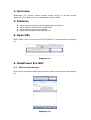
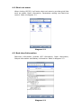
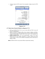
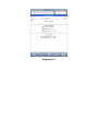
ViewPower Pro for mobile version User’s Manual 1. 2. 3. 4. Overview........................................................................................................... 2 Features............................................................................................................ 2 Open URL.......................................................................................................... 2 ViewPower Pro GUI............................................................................................ 2 4.1 Main control screen ......................................................................................... 2 42 Shortcut menu ............................................................................................... 3 4.3 Realtime Information...................................................................................... 3 44 Basic Information ............................................................................................ 4 45 Login .............................................................................................................. 4 46 Parameter Setting (Refer to diagram 26) ......................................................... 5 4.7 Realtime Control (Refer to diagram 27) .......................................................... 6 1. Overview ViewPower Pro mobile version allows smart phone to remote access ViewPower Pro Web service to centralized monitor UPSs. 2. Features l l l l Simply using smart phone without installing other accessories. Allows realtime monitoring for multiple UPSs Allows realtime setting and controlling Simple screen design shortens transfer time 3. Open URL Enter “http://xxx.xxx.xxx.xxx:15178/VPMobile” in web browser as diagram 11. Diagram 11 4. ViewPower Pro GUI 4.1 Main control screen It will list all connected UPSs when entering main control screen as diagram 21. Diagram 21 42 Shortcut menu When clicking UPS ID, it will enter shortcut menu to provide quick links such as status, Basic information, Parameters setting and Realtime control. Refer to diagram 22. Diagram 22 4.3 Realtime Information Realtime information includes UPS information, Input information, Output information and Battery information. Refer to diagram 23. Diagram 23 44 Basic Information Basic information includes basic information, UPS rated information, battery information and purchasing information. Refer to diagram 24. Diagram 24 45 Login It is necessary to login first for configuration or realtime control of UPS. Refer to diagram 25. Diagram 25 46 Parameter Setting (Refer to diagram 26) 1. Select the functions by clicking “Enable” or “Disable” button. Change the numbers by clicking updown arrows or modify the numbers directly in the number column. 2. Click “Apply” button to save the settings. Each function setting is saved by clicking “Apply” button in each section. 3. Click “Default” button to recover the default setting. Note: Any functions which are not supported by UPS will not be able to access. Ø Alarm Control: If enabled, UPS alarm will be activated. Vice versa. Ø Alarm at bypass mode: If enabled, UPS alarms when it’s working at bypass mode. Vice versa. Ø Alarm at battery mode: If disabled, UPS will not alarm when it’s working at battery mode. Vice versa. Ø Auto reboot: If enabled, UPS will auto recover when AC is recovering. Vice versa. Ø Bypass when UPS is off: If enabled, AC will directly provide power to connected devices when UPS is off. Vice versa. Ø Converter mode: If enabled, the UPS will operate in converter mode. Vice versa. Ø ECO mode: If enabled, the UPS will operate in ECO mode when input voltage is within acceptable range. Vice versa. Ø Battery open status check: If enabled, the monitored UPS will check if the battery connection ok or not when UPS is turned on. Ø Cold start: If disabled, the UPS can be turned on only when AC is normally connected to UPS. Vice versa. Ø Bypass not allowed: If enabled, the UPS will not transfer to bypass mode under any conditions. If disabled, the UPS will be allowed to transfer to bypass mode according to UPS internal setting. Ø Battery deepdischarge protection: If enabled, the monitored UPS shutdown in accordance with the condition of battery and load on battery mode to protect battery. Vice versa. Ø Site fault detection: If enabled, the monitored UPS will beep when the input neutral and hot wires are reversed. Vice versa. Ø P1 Programmable outlet control (battery mode): If enabled, when UPS is running at battery mode, it will cut off P1 outlets after backup setting time arrive. If disabled, UPS will provide continuous power to P1 outlets until the battery is running out. Ø Outlet setting: Users can set limited backup time for P1 outlets when UPS is on battery mode. Ø Battery numbers setting: ² Numbers in parallel: set battery numbers in parallel Ø Voltage and frequency range for bypass mode: Set acceptable voltage and frequency range in bypass mode ² Maximum and minimum voltage: When UPS is on bypass mode and input voltage is out of setting range, UPS will enter battery mode. ² Maximum and minimum frequency: When UPS is on bypass mode and input frequency is out of setting range, UPS will enter battery mode. Ø Voltage range for ECO mode: Set acceptable voltage range for ECO mode. Diagram 26 4.7 Realtime Control (Refer to diagram 27) Ø UPS turn On/Off: Click “On” to turn on the UPS and “Off” to turn off the UPS immediately. Ø Battery SelfTest: Software offers three types of battery selftest: 10second selftest, deep discharge test, and selfdefined selftest. Simply clicking “Start” button from each type. It will execute the selftest immediately. Ø Outlet Control: It will cut off programmable outlets (P1) when setting time arrives. When entering 0 in timer column and click “Start” button, it will cut off outlets immediately when UPS works in battery mode. Note: Different UPSs may access different parameter setting. Diagram 27