1
2
THZ & TDZ
2
TPRG
2
THZ & TDZ
2
Programmable Smart HART
Temperature Transmitter and Display
November 2007
235-797-01D
Programmable Smart HART
Temperature Transmitter and Display
Table of Contents
Introduction .................................................................................................... 4
About this Manual ......................................................................................................... 4
The THZ2 and TDZ2 ....................................................................................................................................................... 4
Model and Serial Numbers ........................................................................................... 4
Specifications ................................................................................................ 5
Input Type and Accuracy Table ................................................................................... 6
Stability, Ambient Temperature Effects and
Normal Mode Rejection Ratio Tables .......................................................................... 7
Dimensions ................................................................................................................... 7
Configuring the THZ2 and TDZ2 ................................................................................................................ 11
Installing the Configuration Software ........................................................................ 11
Connecting the THZ2 or TDZ2 to the PC .................................................................... 12
Necessary Equipment Table ...................................................................................... 12
PC Configuration Software Summary ...................................................... 15
Menu and Tool Bar Legend ........................................................................................ 16
Configuration Screens ............................................................................................... 16
Searching for a Connected Unit ................................................................................ 21
Using the HART Communicator ............................................................... 21
Programming when a Device Description is Available ............................................ 21
The HART Communicator Menu With a Device Description ................................... 23
The HART Communicator Menu Without a Device Description ............................. 28
HART Status Information ........................................................................... 29
Installation ................................................................................................... 32
Mounting the THZ2 and TDZ2 ...................................................................................................................................... 32
Making the Electrical Connections ................................................................................ 32
Recommended Ground Wiring Practices ...................................................................... 32
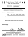
CE Conformity............................................................................................................... 33
Operation ..................................................................................................... 33
HART Protocol .............................................................................................................. 33
Maintenance ................................................................................................................. 33
Customer Support ...................................................................................... 33
Intrinsically-Safe Applications .................................................................. 34
THZ 2 & TDZ 2
Programmable Smart HART
Temperature Transmitter and Display
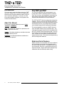
Introduction
This is the user’s manual for Moore Industries’ THZ2
and TDZ2 (TPRG: RTD, T/C, Ohms, mV and Potentiometer inputs) Programmable Smart HART Temperature Transmitter and Display. It contains all of the
information needed to configure, install, operate and
maintain the instruments.
About this Manual
Pay particular attention wherever you see a “Note”,
“Caution” or “WARNING ”.
Note– Information that is helpful for a procedure, condition or operation of the unit.
Caution– Hazardous procedure or condition that could
damage or destroy the unit.
WARNING– Hazardous procedure or condition that
could injure the operator.
The THZ2 and TDZ2
The THZ2 and TDZ2 are 2-wire (loop-powered), userconfigurable, HART®-based temperature transmitters.
Their size, accuracy and compatibility make them the
ideal solution when measurements must be made in
remote or otherwise difficult-to-access locations.
The THZ2 and TDZ2 allow for configuration through two
methods. You may use your PC’s RS-232 serial port
and Moore Industries’ PC Configuration Software (once
installed onto your PC). All configuration parameters
are available through the PC Configuration Softaware.
The second method is to connect a HART Communicator and HART modem into your process loop. You
must ensure that your communicator is configured with
the THZ2 and TDZ2 Device Description (DD). You may
then configure most parameters through the Communicator. Custom Curve variables cannot be entered using the Communicator. They must be configured using
the PC Configuration Software.
Model and Serial Numbers
Moore Industries uses the model and serial numbers of
our instruments to track information regarding each
unit that we sell and service. If a problem occurs with
your instrument, check for a tag affixed to the unit listing these numbers. Supply the Customer Support representative with this information when calling.
4
The Interface Solution Experts
THZ 2 & TDZ 2
Programmable Smart HART
Temperature Transmitter and Display
Specifications
HART Address Range: 0-15
Specifications (1-15 are for multidrop
loops)
Transmission Speed:
1200 bps
Character Format:
1 Start Bit - 8 Data Bits 1 Odd Parity Bit - 1 Stop Bit
Performance Input Accuracy: Refer to
Table 1
Output Range: 4-20mA
Analog Output Accuracy:
±0.01% of maximum span
Overall Accuracy: The
overall accuracy of the unit
is the combined input and
output accuracy. It includes
the combined effects of
linearity, hysteresis,
repeatability and adjustment
resolution. It does not
include ambient temperature
effect. For T/C input only,
add the Reference Junction
Compensation error
Reference (Cold) Junction
Compensation: ±0.25°C
(±0.45°F)
Stability: Refer to Table 2
Isolation: THZ2: HPP,
1500Vrms between input
and output continuous; DIN,
500Vrms between input and
output continuous;
TDZ2: 500Vrms input-tooutput continuous, and will
withstand a 500Vac
dielectric strength test for
one minute with no breakdown
Response (Rise) Time:
100msec maximum for the
output to change from 10%
to 90% for an input step
change of 0% to 100%
Step Response Time:
500msec maximum,
256msec typical from the
time an input is applied until
the output reaches 90% of
its final value
Ripple: 10mVp-p
measured across a
250 ohm load resistor at
frequencies up to 120Hz
Over-voltage Protection:
±5Vdc peak, maximum
Digital Input Filter: Userprogrammable; 50/60Hz
Power Supply Effect:
±0.002% of span per 1V
change
Performance Load Effect: Negligible
(Continued) within specified power limits
Load Capability:
(500 ohms@24V)
Supply Voltage - 12V
= Ohms
0.024A
Burnout Protection:
User-programmable,
Upscale 20 to 23.6mA;
Downscale 3.6 to 4.0mA
Output Current Limiting:
User-programmable, 3.6 to
4.0mA and 20 to 23.6mA for
input under/over range;
25mA, maximum (hardware
limit)
T/C Input Impedance:
40Mohms, nominal
RTD & Ohms Excitation:
250 microamps, ±10%
RTD Lead Wire Resistance
Maximum: RTD resistance
+ 2X lead wire resistance
< 4000 ohms; Recommended lead wire resistance
for three wire connections:
<35 ohms/wire; 10 ohms
copper sensor <5 ohms
Sensor Lead Resistance
Effect: 2-wire sensors:
Error = 1.0 ohm in reading/
ohm of lead resistance;
3-wire sensors:
Error = 1.0 ohm in reading/
ohm of unbalanced
resistance; 4-wire sensors:
No effect
Damping:
User set; 0-30 seconds
Resolution:
Input, 20-bit; Output, 16-bit
Power Supply
Requirement: 12-30Vdc
for I.S. version; 12-42Vdc
for standard version
Display Type: TDZ2; Top Row,
(TDZ2 only) 10mm (0.4 in) high black
digits on a reflective
background; Bottom Row,
6mm (0.225 in) high digits on
a reflective background;
Two-digit HART address
indicator
Format: Two rows of five
alphanumeric characters
Display Decimal Points:
(TDZ2 only, Can be user-set to enable
continued) automatic adjustment of
decimal point to 2 decimal
places; Allowed decimal
places: Auto, 1, 2 or 3
Range: -99999 to 99999
Minimum Display Span:
1.00
Ambient Operating Range:
Temperature -40°C to +85°C
(-40°F to +185°F)
Storage Range:
-40°C to +85°C
(-40°F to +185°F)
Relative Humidity:
0-95%, non-condensing
Ambient Temperature
Effect: See Table 3
Effect on Reference
(Cold) Junction Compensation: ±0.005°C per
°C change of ambient
temperature
Startup Time:
<0.5sec, maximum
Noise Rejection:
Common mode,
100dB@50/60Hz; Normal
Mode: Refer to Table 4
RFI/EMI Immunity:
THZ2: HPP and DIN
10V/m@80-1000MHz,
1kHz AM, when tested
according to IEC 61326
with 0.5% of span or less
error; With -RF DIN Option:
20V/m@80-1000MHz,
1kHz AM, when tested
according to IEC 61326
with 0.5% of span or less
error;
TDZ2: 20V/m when tested
according to IEC 61326
with 0.5% of span or less
error
Weight THZ2 DIN: 221g (7.9 oz)
THZ2 HPP: 91g (3.2 oz)
THZ2 HPP in LH1:
423g (15.1 oz)
THZ2 HPP in LH2:
644g (22.9 oz)
TDZ2 HP:
182g (6.4 oz)
TDZ2 HP in BH:
1.4kg (50.2 oz)
TDZ2 HP in D-Box:
672g (23.4 oz)
Specifications and information subject to change without notice.
The Interface Solution Experts
5
THZ 2 & TDZ 2
Programmable Smart HART
Temperature Transmitter and Display
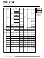
Table 1. THZ 2 and TDZ 2 Input and Accuracy Table
Input
Type
α
Ohms
Conformance
Range
Minimum
Span
Input
Accuracy
Maximum
Range
Sensor-toTransmitter
Matching
100
Up to ±0.014°C
(±0.025°F) system
accuracy*.
200
300
0.003850
400
-240 to 960°C
-400 to 1760°F
-200 to 850°C
-328 to 1562°F
500
1000
10°C
(18°F)
Platinum
100
RTD
±0.1°C
(±0.18°F)
200
0.003902
400
-100 to 650°C
-148 to 1202°F
-150 to 720°C
-238 to 1328°F
-200 to 510°C
-328 to 950°F
-80 to 320°C
-112 to 608°F
-50 to 250°C
-58 to 482°F
±0.85°C
(±1.53°F)
-240 to 580°C
-400 to 1076°F
-100 to 360°C
-148 to 680°F
-65 to 280°C
-85 to 536°F
500
1000
0.003916
100
Nickel
0.00672
120
Copper
0.00427
9.035
Direct Resistance
Ohms
n/a
Potentiometer
T/C
Millivolts
6
0-4000 ohms
0-4000 ohms
10 ohms
±0.4 ohms
0-4095 ohms
125, 250, 500, 1k,
2k, 4k ohms
0-100%
10%
±0.1%
0-100%
J
n/a
n/a
-180 to 760°C
-292 to 1400°F
35°C
63°F
±0.25°C
(±0.45°F)
-210 to 770°C
-346 to 1418°F
K
n/a
n/a
-150 to 1370°C
-238 to 2498°F
40°C
72°F
±0.3°C
(±0.54°F)
-270 to 1390°C
-454 to 2534°F
E
n/a
n/a
-170 to 1000°C
-274 to 1832°F
35°C
63°F
±0.2°C
(±0.36°F)
-270 to 1013°C
-454 to 1855.4°F
T
n/a
n/a
-170 to 400°C
-274 to 752°F
35°C
63°F
±0.25°C
(±0.45°F)
-270 to 407°C
-454 to 764.6°F
R
n/a
n/a
0 to 1760°C
32 to 3200°F
50°C
90°F
±0.55°C
(±0.99°F)
-50 to 1786°C
-58 to 3246.8°F
S
n/a
n/a
0 to 1760°C
32 to 3200°F
50°C
90°F
±0.55°C
(±0.99°F)
-50 to 1786°C
-58 to 3246.8°F
B
n/a
n/a
400 to 1820°C
752 to 3308°F
75°C
135°F
±0.75°C
(±1.35°F)
200 to 1836°C
392 to 3336.8°F
N
n/a
n/a
-130 to 1300°C
-202 to 2372°F
45°C
81°F
±0.4°C
(±0.72°F)
-270 to 1316°C
-454 to 2400.8°F
C
n/a
n/a
0 to 2300°C
32 to 4172°F
100°C
180°F
±0.8°C
(±1.44°F)
0 to 2338°C
32 to 4240.4°F
DC
n/a
n/a
-50 to 1000mV
4mV
15 microvolts
-50 to 1000mV
The Interface Solution Experts
*High-accuracy
measurements are achieved
by using a 4-wire, 1000 ohm
platinum RTD with a span of
100°F (50°F minimum)
calibrated in our sensormatching calibration bath.
THZ 2 & TDZ 2
Programmable Smart HART
Temperature Transmitter and Display
Table 2.
Table 4. Normal Mode Rejection Ratio Table
Long-Term Stability Table
Stability (%
of maximum
span)
Input to Output
Max. p-p Voltage Injection
for 70dB at 50/60Hz
T/C: J, K, N, C, E
150mV
T/C: T, R, S, B
80mV
Pt RTD: 100, 200, 300 ohms
250mV
Pt RTD: 400, 500, 1000 ohms
1V
Ni: 120 ohms
500mV
Cu: 9.03 ohms
100mV
Sensor Type
Input to HART
1 yr
3 yrs
5 yrs
1 yr
3 yrs
5 yrs
T/C, mV
0.08
0.14
0.18
0.008
0.015
0.019
RTD, Ohm,
Potentiometer
0.09
0.16
0.21
0.047
0.081
0.104
Resistance
mV
1-4kohms
250-1000
0.25-1kohms
62.5-250
0.125-0.25kohms 31.25-62.5
Table 3.
Ambient Temperature Effects Table
Sensor
Type
Digital Accuracy per 1°C (1.8°F)
change in Ambient
Analog Accuracy per 1°C (1.8°F)
change in Ambient
RTD
0.003°C
0.004% of span (16mA)
T/C
0.003°C + 0.005% of reading
0.004% of span (16mA)
Millivolt
0.005mV + 0.005% of reading
0.004% of span (16mA)
Ohm
0.002 ohms + 0.005% of reading
0.004% of span (16mA)
1V
250mV
100mV
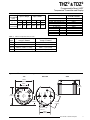
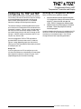
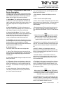
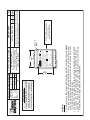
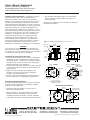
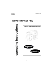
Figure 1. THZ 2 Hockey-Puck (HPP Housing) Dimensions
TOP
SIDE
BOTTOM
52mm
(2.04 in)
25mm
(1.00 in)
+PS
30mm
(1.18 in)
CL
–PS
49mm
(1.92 in)
1
2
3
4
27mm
(1.05 in)
CL
CL
CL
CL
33mm
(1.30 in)
4 X 40
0.125 in depth
2 Places
33mm
(1.30 in)
The Interface Solution Experts
7
THZ 2 & TDZ 2
Programmable Smart HART
Temperature Transmitter and Display
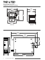
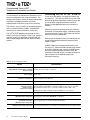
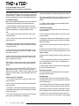
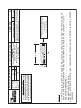
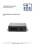
Figure 2. TDZ2 Hockey-Puck (HP Housing) Dimensions
76mm
(3.00 in)
66mm
(2.58 in)
61mm
(2.40 in)
TDZ2
18mm
(0.70 in)
+PS
-PS
1
2
3
62mm
(2.45 in)
83mm
(3.25 in)
4
43mm
(1.70 in)
64mm
(2.50 in)
SIDE VIEW
FRONT VIEW
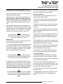
Figure 3. THZ 2 DIN Dimensions
138mm
(5.43 in)
When Installed
1
2
3
133mm
(5.24 in)
When Installed
43mm
(1.69 in)
4
THZ2
COM
C
L
80mm
(3.15 in)
+PS –PS
25mm
(1.00 in)
8
The Interface Solution Experts
110mm
(4.33 in)
113mm
(4.45 in)
THZ 2 & TDZ 2
Programmable Smart HART
Temperature Transmitter and Display
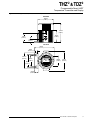
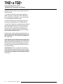
Figure 4. BH Housing Dimensions (For use with the TDZ 2)
SIDE VIEW
102mm
(4.02 in)
119mm
(4.69 in)
GND
76mm
(2.99 in)
1/2 NPT
57mm
(2.24 in)
22mm
(0.87 in)
TOP VIEW
64mm
(2.52 in)
10mm
(0.38 in)
102mm
(4.02 in)
TDZ2
68mm
(2.68 in)
602.78
ADDR
DEG C
0
84mm
(3.31 in)
+PS
-PS
1
2
3
68mm
(2.68 in)
124mm
(4.88 in)
4
25mm
(1.00 in)
The Interface Solution Experts
9
THZ 2 & TDZ 2
Programmable Smart HART
Temperature Transmitter and Display
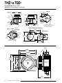
Figure 5. LH Housing Dimensions (For use with the THZ2 HPP)
Safety Lock
(LH2 only)
87mm
(3.43 in)
51mm
(2.01 in)
BOTTOM
SIDE
Metal Tag
Conduit
Entry Port
92mm
(3.62 in)
30mm
(1.18 in)
9mm
(0.35 in)
Process Connection
1/2-in NPT (N and M models) or
G½ (BSP) (C models)
2-INCH PIPE MOUNTING HARDWARE
M4.0 x 0.7 INSIDE Instrument
Mounting Holes
(4 places)
40mm (1.56 in)
Instrument
Mounting
Holes
33mm
(1.30 in)
10-32
Mounting
Holes (2)
DIA. 72mm
(DIA. 2.83 in)
FRONT
61mm
(2.40 in)
84mm
(3.31 in)
89mm
(3.5 in)
2-in Pipe Bracket
Mounting Holes (4)
61mm
(2.40 in)
CL
Ground
I.D. 62mm x 19mm Deep
(2.44 in x 0.75 in Deep)
61mm
(2.40 in)
Figure 6. D-BOX Housing Dimensions (For use with the TDZ2)
Conduit
Fitting
130mm
(5.12 in)
116mm
(4.57 in)
118mm
(4.65 in)
112mm
64mm
(4.41 in) (2.52 in)
83mm
(3.27 in)
Body
Bezel
Cover
Interior Diameter
81mm (3.2 in)
Instrument
Tag
CL
84mm
(3.31 in)
10
The Interface Solution Experts
27mm
(1.06 in)
THZ 2 & TDZ 2
Programmable Smart HART
Temperature Transmitter and Display
Configuring the THZ2 and TDZ2
One of the benefits of these transmitters is that there
are no internal or external controls to adjust or settings
to change. All operating parameters are set using
either a HART Communicator or a PC and Moore
Industries’ Intelligent PC Configuration software.
The software settings are downloaded to the transmitter in the form of a Configuration File and stored in the
instrument’s memory. You can save a backup copy of
the file on your PC hard drive or external media. The
transmitter communicates with the PC through an RS232 port. A HART modem connection to the PC’s serial port may also be used.
Installing the Configuration Software
Refer to Table 5 for the equipment needed.
1.
Insert the Moore Industries Interface Solution
PC Configuration Software CD into the CD drive
of the PC. Access the CD and open the
THZ2_TDZ2 PC Configuration Software folder.
2.
Double-click the installation program located in
the folder. Follow the prompts to correctly
install the program.
Once the Configuration Program is installed on the PC,
the THZ2 or TDZ2 can be connected to equipment to
simulate input and monitor output. You can then
change the transmitter’s operating parameters.
You can configure the THZ2 or TDZ2 with either a
standard HART Communicator or our PC software.
Figures 7 and 8 (depending upon your instrument’s
housing) and Table 5 provide the information you need
to configure your unit.
Using a PC
If you are going to use a PC to configure your unit,
first install the software as described on the next page,
then setup the hardware as shown in Figures 7 or 8
(depending upon your instrument’s housing).
The Interface Solution Experts
11
THZ 2 & TDZ 2
Programmable Smart HART
Temperature Transmitter and Display
No Transmitter Needed
It is not necessary to connect the transmitter to a PC
to create configuration files using the software. The
Configuration Program can be run without connecting a
transmitter, and most parameters can be set
without benefit of input from a sensor or transmitter.
This makes it easy to create a set of operating parameters, save them to external media, and download
them to one or more transmitters at a later time.
The THZ2 or TDZ2 must be connected to the PC in
order to: trim input, trim output, assign a tag, perform a
loop test, receive (via download) a configuration file
and save the configuration file from the transmitter’s
memory.
Connecting the THZ2 or TDZ2 to the PC
To set any of the options, you must first connect the
unit to the PC. The THZ2 and TDZ2 all have the same
terminal designations regardless of housing style, and
all can be setup using the connections shown in
Figures 7 and 8 (depending upon your instrument’s
housing).
Establish a simple current loop for the transmitter by
connecting a 24 Volt power supply, a 250 ohm resistor
and the transmitter in series. See Table 5 for information on the necessary equipment.
Connect your instrument to the PC via the RS-232 serial port using the Moore Industries Interface Cable
listed in Table 5.
A HART modem may also be used to connect your
unit to the PC. Connect the RS-232 end of the modem
to the PC’s COM port, then connect the HART output
end of the modem (two hook-up wires) across the
transmitter or the load resistor. For hook-up diagrams,
refer to Figures 7 or 8 (depending upon your
instrument’s housing).
Table 5. Necessary Equipment Table
Device
Specifications
Variable Input Simulator for Thermocouple,
RTD, Millivolt, Potentiometer, or Decade
Resistance Box
Power Supply
Precision Load Resistor
Multimeter (optional)
Personal Computer
(Required only if
using a PC for setup)
Variable; Accurate to ±0.05% of unit span
24Vdc, ±10%
250 ohms, ±0.01% HART specifies that total loop resistance is to be maintained
between 250 ohms and 1100 ohms.
Accurate to ±0.025% of span; e.g., Fluke Model 87
Pentium-based PC, or equivalent with:
CD Drive; 4Mb free RAM (8Mb recommended); 20Mb free disk space on hard drive
(More RAM and hard disk space is required for Windows 98, NT, 2000 or XP)
Operating System: Microsoft Windows® 98, NT, 2000 or XP, one serial port
Moore Industries Interface Cable
HART Modem Cable
(Required only if using a PC)
Moore Industries part number 803-048-26, or equivalent
Moore Industries PC
Configuration Software
(Required only if using a PC)
Version 1.0 or greater, successfully installed to the hard drive
HART Communicator
(Required only if NOT using a PC)
12
803-040-26
The Interface Solution Experts
Fisher-Rosemount Model 275 or equivalent (with THZ2/TDZ 2 Device Description loaded)
THZ 2 & TDZ 2
Programmable Smart HART
Temperature Transmitter and Display
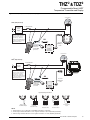
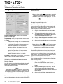
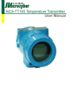
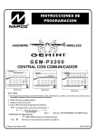
Figure 7. THZ2 (HPP) and TDZ 2 (HP) Hook-Up Diagrams
Current Meter
THZ 2 (HPP) Hook-Up
+
–
Load=250 ohms
12-24Vdc
Power
Supply
–
+
THE HART Communicator
or the PC can be connected
at any point on the output
side of the loop. Total loop
resistance must equal between
250 and 1100 ohms for proper
HARTcommunications.
+PS
1
OR
–PS
2
To serial
(COM) port
of PC
HART Modem
connects to
serial (COM)
port of PC
4
3
PC
Current Meter
TDZ 2 (HP) Hook-Up
–
Load=250 ohms
–
+
12-24Vdc
Power
Supply
TDZ2
+
THE HART Communicator
or the PC can be connected
at any point on the output
side of the loop. Total loop
resistance must equal between
250 and 1100 ohms for proper
HARTcommunications.
+PS
-PS
1
2
3
4
OR
To serial
(COM) port
of PC
HART Modem
connects to
serial (COM)
port of PC
PC
Input Hook-Up Connections
1
4
3
1
2
4
3
+
1
1
1
2
2
4
3
2
2
4
4
3
3
–
Thermocouple
and Millivolt Input
2-Wire RTD
or Decade
Resistance Box
3-Wire RTD
or Decade
Resistance Box
Potentiometer
Input
4-Wire RTD
or Decade
Resistance Box
NOTE:
1. Terminal blocks can accommodate 14-22 AWG (2.0-0.3mm 2 ) solid wiring.
2. HP Housing terminals utilize M2.6 screws. Tighten terminals to 2.8 in lb (0.31Nm) (maximum).
3. HPP Housing terminals utilize #4 screws. Tighten terminals to 4.7 in lb (0.53Nm) (maximum).
The Interface Solution Experts
13
THZ 2 & TDZ 2
Programmable Smart HART
Temperature Transmitter and Display
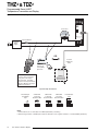
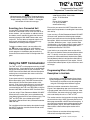
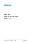
Figure 8. THZ2 DIN Hook-Up Diagram
1
2
3
4
THZ2
Current Meter
COM
–
–
+PS –PS
Load = 250 ohms
+
12-24Vdc
Power
Supply
+
OR
To serial
(COM) port
of PC
HART Modem
connects to
serial (COM)
port of PC
THE HART Communicator
or the PC can be connected
at any point on the output
side of the loop. Total loop
resistance must equal between
250 and 1100 ohms for proper
HARTcommunications.
PC
Input Hook-Up Connections
Thermocouple
and Millivolt
Input
+
2-Wire RTD
or Decade
Resistance Box
3-Wire RTD
or Decade
Resistance Box
4-Wire RTD
or Decade
Resistance Box
Potentiometer
Input
1 2 3 4
12 34
1 2 3 4
1 2 3 4
–
12 3 4
NOTE:
1. Terminal blocks can accommodate 14-22 AWG (2.0-0.3mm 2 ) solid wiring.
2. DIN Housing terminals on TPRG input instruments utilize #6 screws. Tighten terminals to 7.9 in lb (0.89Nm) (maximum).
14
The Interface Solution Experts
THZ 2 & TDZ 2
Programmable Smart HART
Temperature Transmitter and Display
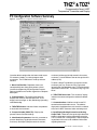
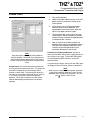
PC Configuration Software Summary
Figure 9. THZ2/TDZ2 PC Configuration Software Main Screen
1
2
8
3
4
5
6
7
Once the default configuration has been saved to your
PC or external media, it is safe to program other
parameters. The PC Software is made up of these
sections:
1. Menu Bar/Tool Bar– Dropdown menus and
corresponding icons allow you to perform various
functions throughout the PC Configuration Program.
Refer to the Menu and Tool Bar Legend for a complete
description.
2. Program Status– This portion of the program
displays the activity of the connected unit. It will
display such messages as: Idle, Monitoring, Uploading
and Downloading.
3. THZ2/TDZ2 Status– Indicates if there are problems
or faults with the instrument.
4. Process Variable (PV/SV/TV)– Displays the
present Process Variable readings.
5. Identification Parameters– Use this parameter to
place an identifying Tag (8 alphanumeric characters,
maximum), Descriptor (16 alphanumeric characters,
maximum) or Message (32 alphanumeric characters,
maximum). Use the Address box to change the unit’s
address (0-15).
To utilize a longer Tag identifier (up to 32 characters,
maximum) you may access the Long Tag feature
located in the View dropdown menu. Enter the desired
information and click Set. To view the Long Tag, click
Read.
6. THZ2/TDZ2 Device Info– This “read-only” display
indicates instrument configuration and device identification.
7. Communications– Notifies user of current PC
connection/communications status. The address
displayed in the Address box must match the address
of the unit if HART Communciations are being used.
8. Input/Display/Scaling/Custom Curve/Analog
Output Tabs–These tabs change the right side of the
screen to allow you to set the appropriate part of the
THZ2’s and the TDZ2’s configuration. See corresponding sections of this manual for additional information
regarding these tabs.
The Interface Solution Experts
15
THZ 2 & TDZ 2
Programmable Smart HART
Temperature Transmitter and Display
Menu and Tool Bar Legend
Allows such functions as New,
Open, Save and Print functions
Controls whether Tool and Status
Bars are viewed on the screen as
well as Additional Status
Information, Long Tag and
Device Information
Allows you to Upload and
Download configurations and
perform an Address Search
Configuration Screens
Note:
Unless otherwise noted, ensure that the PC
Configuration Program is idle before making any
selections or configuration changes to the program.
Also, when attempting to download or upload,
monitoring must be stopped. To do this, click Stop
in the Monitoring dropdown menu, or click the Stop
Monitoring icon on the Tool Bar.
Input
Allows selection of PC COM ports
as well as Communcation Method
(Auto, RS232 or HART)
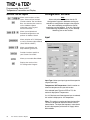
Figure 10. Input Tab
Allows you to Monitor and
Stop monitoring processes
Provides functions specific to
your Custom Curve table
Allows you to enable Burst Mode
Displays the version of the
PC Configuration Program
Input Type– Select your input type and the respective
range of your input.
Temperature / SV Temperature– Use this section to
select the temperature unit you wish to view.
If the selected Input Type is an RTD or T/C, this
section is displayed as Temperature.
If a mV, Resistance or Potentiometer input is selected,
this section is displayed as SV Temperature.
Filter– This setting is used to configure the input filter.
The filter is designed to reduce the effects of mainsinduced noise. The input filter frequency value should
be set to the frequency of the local AC supply–either
50Hz or 60Hz.
16
The Interface Solution Experts
THZ 2 & TDZ 2
Programmable Smart HART
Temperature Transmitter and Display
Broken Wire Detection– During operation, the THZ2
and TDZ2 send random microamp pulses through input
wiring to check for broken wiring or a burned out sensor.
To utilize Broken Wire Detection, check the Enabled
box. If a failure is detected, a message will appear in
the THZ2/TDZ2 Status box.
Running Average Filter Settings– This function is for
filtering the input signal. The THZ2 and TDZ2 provide
this filter with a user-selected range between 1 and 16.
Factory default is 1.
Note:
A higher Running Average Filter setting provides
smoother output transitions; however, reduces
response time. Conversely, a lower setting provides
a faster response time, but may seem more
unstable.
PV Damping–PV Damping allows you to introduce a
delay into the response of your unit in order to stop
short-lived spikes from initiating faults and generating
fault messages.
The configured damping period will determine the time
response that the analog output will take to achieve a
66% change in output in response to a stepped input.
To enable PV Damping, select the Enabled button.
Use the arrows to select a value between 1sec and
30sec.
Sensor Trimming– Sensor Trimming increases the
measurement accuracy of your instrument by matching
the reading of its actual input, to either a calibrated
source or the device to which it is connected. This
verifies that the input to the transmitter is being interpreted correctly.
You may trim any point between 0% and 100% along
the scale. Note that one-point trimming applies an
offset to the sensor reading, while two-point trimming
applies both an offset and a gain.
Follow the steps below in order to perform sensor
trimming.
1.
Select either 1 Point (one-point trimming) or
2 Points (two-point trimming) by clicking the
appropriate button. Each pair consists of Set
Value and Trim fields.
2.
Enter the values that require trimming into the
Set Value field and click Set.
3.
Apply the targeted signal to the input, wait until
it settles, and click Trim to capture the
measured value. If you chose 2 Points, repeat
the step above for the second point.
Note:
Once you have configured all parameters, download
to the unit by selecting Download in the Transfer
dropdown menu located in the Menu Bar. Or, click
the
button in the Tool Bar.
Sensor Range– Allows you to set your upper and lower
range values within the range chosen in the Input Type
section.
The desired Upper and Lower Range settings can be
entered via your PC keyboard or captured. To capture
an input, follow the steps below.
1.
Apply the desired Upper Range input and press
the corresponding Capture button.
2.
Next, apply the desired Lower Range input and
press the corresponding Capture button.
The Interface Solution Experts
17
THZ 2 & TDZ 2
Programmable Smart HART
Temperature Transmitter and Display
Display
(TDZ2 Only)
Scaling
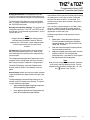
Figure 12. Scaling Tab
Figure 11. Display Tab
Display Source– Select how your reading is displayed.
Primary Variable–The reading will be displayed as the
Primary Variable value.
Output Current–Your reading will be displayed as the
output current value.
Toggle PV / mA– Every four seconds your display will
toggle between the primary variable and mA (current)
reading.
Percent of Range– Selecting this allows your instrument to display its output in the percent of the range at
which the output current is transmitting (0-100%).
Custom Label– The Custom Label is used to display a
calculated or scaled variable. Clicking the Use custom
label box causes the instrument to always display the
custom label as Engineering Units (EGU).
1.
Check the Use custom label box.
2.
Enter the label you wish viewed into the text
box. This value is limited to five characters.
Precision– Select the number of decimal places (up to
three) of your display.
Note:
Once you have configured all parameters, download
to the unit by selecting Download in the Transfer
dropdown menu located in the Menu Bar. Or, click
the
button in the Tool Bar.
18
The Interface Solution Experts
Note:
Using the Scaling feature will disable the Custom
Curve capability. Since both are scaling features
used to manipulate the appearance of your process
variable, only one of these functions may be used at
a time.
Scaling– This allows you to customize your display
for your application. By example, if your process is
sending a -200°C to 850°C signal to the THZ2 or TDZ2
and you wish to view the input as 0-100% then this
can be accomplished with the Scaling feature.
To scale your instrument, perform the following steps:
1.
Check the Enabled box. The Sensor Range
boxes will display the range selected in the
Input Type section of the Input screen.
2.
In the Scaled to text boxes, enter the values
you wish displayed when your input is at its
Zero Range and Full Range.
Once downloaded, your unit will display the scaled
values on its LCD and through HART communication.
Scaling PV Units of Measure– Use this to select a
preset HART EGU process variable display for your
scaled values. These HART EGU codes are compatible with HART Revision 5, and earlier, communications.
To customize your display and set your own EGU, open
the Display screen and use the Custom Label feature.
Note:
Once you have configured all parameters, download
to the unit by selecting “Download” in the Transfer
dropdown menu located in the Menu Bar. Or, click
the
button in the Tool Bar.
THZ 2 & TDZ 2
Programmable Smart HART
Temperature Transmitter and Display
Custom Curve
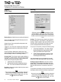
Figure 13. Custom Curve Tab
Note:
Using the Custom Curve feature will disable the
Scaling capability. Since both are scaling features
used to manipulate the appearance of your process
variable, only one of these functions may be used at
a time.
Custom Curve–The Custom Curve feature allows you
to set up your own custom curve table. This allows you
to tell the transmitter what it should output when it
receives a certain input. This feature also allows you
the ability to write a table in Microsoft® Excel, save it in
a .csv format, and import it into the Configuration
Software. This makes it simple to save the custom
table for downloading to multiple units or for backup
purposes.
To create a custom curve:
1.
Click the Enabled box.
2.
Select the number of points for your curve (128
points maximum) and enter it into the No Of
Points text box.
3.
In the Custom Curve (Y) Range text boxes,
enter the values you wish displayed, and
represented as your 4-20mA span, when your
input is at its upper and lower ranges.
4.
Type your individual values in the X data and
Ydata columns. Source variables are inserted
into the X Column, while the corresponding data
is inserted into the Y Column.
5.
After all of your data has been entered, you
must use the Custom Curve dropdown menu to
save your newly created custom table (Save
Custom Curve) and to download it to your
instrument (Download Custom Curve).
Custom Curve PV Units of Measure– Use this to
select a preset HART EGU process variable display for
your custom curve values. These HART EGU codes
are compatible with HART Revision 5, and earlier,
communications.
To customize your display and set your own EGU, open
the Display screen and use the Custom Label feature.
Note:
Once you have configured all parameters, download
to the unit by selecting “Download” in the Transfer
dropdown menu located in the Status Bar. Or, click
the
button in the Tool Bar.
The Interface Solution Experts
19
THZ 2 & TDZ 2
Programmable Smart HART
Temperature Transmitter and Display
Analog Output
Figure 14. Analog Output Tab
Hold Last– This will maintain the last value present
before the failure.
Note:
Once you have configured all parameters, download
to the unit by selecting Download in the Transfer
dropdown menu located in the Menu Bar. Or, click
the
button in the Tool Bar.
Output Current– While in monitoring mode, this
displays the present output value.
Trimming– Output Trimming increases the accuracy of
your instrument by calibrating its analog output to the
device that is receiving the output. This ensures that
the instruments are matched to each other.
Process Variable Range– Displays the selected
process variable range.
Output Range– Sets your output limits. Default value
is 4-20mA.
1.
Enter your low and high limit values into the text
boxes.
2.
In the Under Range Min. Value box, enter the
lowest limit your output can reach before
indicating a failure. The allowed limits are
3.6mA to 4.0mA. Default is 3.8mA.
3.
In the Over Range Max. Value box, enter the
highest limit your output can reach before
indicating a failure. The allowed limits are
20.0mA to 23.6mA. Default is 21.8mA.
Fail Mode– In the case of an input failure, you have the
ability to set an indicator to alert of the failure.
High– Selecting High will send the output to a userselected high value between 20.0mA and 23.6mA.
Default is 23.6mA.
1.
Click the Lower button to fix the lower output
range.
2.
To “fine tune” trimmed values, place the value
read on the external ammeter in the Measured
Loop Current text box and click Trim.
3.
Click the Upper button and repeat Step 2 to trim
the upper output range.
4.
Once you have perfomed your output trimming,
click Unfix.
Note:
Do not click the Reset button in the Trimming menu
unless you want to disregard your trimmed values
and return to the manufacturer’s trim values.
Output Test– This test may be performed in order to
check output performance and accuracy and to trim
other instruments in your setup. Your output will be a
current value, in mA, equal to the value you enter into
the text box. You can check the other devices on the
system and calibrate them to this signal.
This feature is independent of the input. If you find
that the output requires adjustment, you may perform
the Trimming function.
1.
Ensure that THZ2/TDZ2 monitoring is stopped.
In the Fix current text box, enter a value
between 3.6mA and 23.6mA and click the Fix
button.
2.
Return to monitoring the THZ2/TDZ2. You will
see the “fixed” value in the Output Current
display and on the external ammeter connected
to the output.
3.
Once you have finished, stop monitoring your
instrument and click Unfix.
Low– By selecting Low, the failure indication value will
be driven to a user-selectable value between 3.6mA
and 4.0mA. Default is 3.6mA.
Note:
When setting Fail Mode to Low on the TDZ2 while it
is operating at temperatures below -30 Degree C, set
the Output Fail Current to 3.8mA, or higher, to ensure
full HART communication functionality.
To select a value other than the default setting for High
and Low fail mode, enter the value into the Sensor Error
Value text box.
20
The Interface Solution Experts
THZ 2 & TDZ 2
Programmable Smart HART
Temperature Transmitter and Display
Note:
While performing Analog Output Trimming functions,
you may notice a message in the THZ2/TDZ2 Status
display reading **OUTPUT FIXED**” Clicking the
Unfix button will clear this message.
Searching for a Connected Unit
If using HART Communications and you need to
search for a connected THZ2 or TDZ2 unit with an unknown address, you can perfom an address search.
An address search sequentially polls short frame addresses 0 through 15 with HART Command 0–read
unique ID. The first device to respond stops the address search and the device’s configuration is uploaded to the PC Configuration Program.
To begin an address search, you may either click
the
button on the tool bar or select Address
Search from the View dropdown menu. You can view
search progress in the Address box located in the
Communications section of the PC Configuration Program.
Using the HART Communicator
The THZ2 and TDZ2 can be programmed using a HART
Communicator. If your communicator is equipped with
the Device Description (DD) for your transmitter, The
HART Communicator Menu with a Device Description
section gives an overview of the menus and instructions for programming.
If your communicator is not equipped with the required
Device Description, go to The HART Communicator
Menu without a Device Description section of this
manual. Even if your communicator is not up to date,
most of the important programming features can be
accessed without the THZ2 and TDZ2 DD by using the
Generic HART DD available on HART Communicators.
If you are using a Fisher-Rosemount Model 375 HART
Communicator, or other host, you may download the
latest Moore Industries DD at www.hartcomm.org. The
THZ2 and TDZ2 DDs are available on the HART
Foundation’s Device Driver Library Release December
2005 and later.
For installation of the latest device description through
the HART Foundation, send the Communicator to the
the following address:
HART Communication Foundation
9390 Research Blvd., Suite I-350
Austin, TX 78759-6540
USA
Phone: (512) 794-0369
Fax: (512) 794-3904
www.hartcomm.org
Ensure that you contact the HART Foundation to determine their requirements in sending the instrument to
their facility.
If you are using a Fisher-Rosemount Model 275 HART
Communicator, perform the following steps to determine if your communicator has the appropriate Device
Description. With the communicator turned on, press
1 to select Offline then press 1 again to select New
Configuration. A list of companies will appear which, if
you have the appropriate Device Description, will include Moore Industries THZ2/TDZ2.
If you find that you require the latest version of the
DD, you must send the Communicator to Moore Industries. To do this, contact our Customer Service department for a Returned Material Authorization (RMA).
Include Moore Industries’ configuration sheet indicating the Device Descriptions that you require. We will
load the Device Descriptions of your choice for a nominal charge.
Programming When a Device
Description is Available
Note:
All parameters, except the Custom Curve feature,
can be configured using the HART Communicator.
The Custom Curve table can only be configured
using the PC Configuration Software Program.
With the transmitter connected as illustrated in
Figures 7 or 8 (depending upon your instrument’s housing) apply power and turn on the communicator. After
a brief self-test, the communicator will show the main
menu and identify the unit as a THZ2 or TDZ2.
This section contains the instructions for programming
the transmitter using a HART Communicator that has
been programmed with a HART Device Description. If
your communicator does not have the appropriate Device Description, skip to The HART Communicator
Menu without a Device Description section of this
manual.
Figure 15 shows an overview of the programming
menus for the configuration process.
The Interface Solution Experts
21
THZ 2 & TDZ 2
Programmable Smart HART
Temperature Transmitter and Display
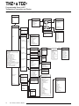
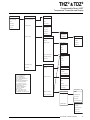
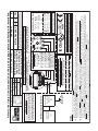
Figure 15. THZ 2 and TDZ 2 HART Communicator Configuration Menu Summary
Online Menu
1
1 Model
2 Device Setup
3 PV
4 AO
4 LRV
6 URV
Device Setup
Configure Sensor
Sensor Type
RTD
1 Sensor Type
2 Sensor Serial
Number
3 PV Damping
4 Sensor
Information
1 RTD2W
2 RTD3W
3 RTD4W
4 mV
5 OHMS2W
6 OHMS3W
7 OHMS4W
8 T/C
9 T/C w/RJC
10 Potentiometer
1 PT3850 100
2 PT3850 200
3 PT3850 300...
Sensor Information
Thermocouple
1 LSL
2 USL
3 Min Span
1 T/C J
2 T/C K
3 T/C E
4 T/C T
5 T/C R
6 T/C S
7 T/C B
8 T/C N
9 T/C C
2
1 Process Variable
Process Variable
3
1 PV
2 % Range
3 AO
4 Term. Temp
Setup
2 Setup
Key
% RANGE = Output Current
in % of Span
# PREAMBLES = Number of Preamble
Characters
AO = Output Current
AO ORV = Analog Output
Over Range Value
AO URV = Analog Output
Under Range Value
DAMP = Damping Value
DEV ID = Device Identification
DIAG = Diagnostic
LRV = Lower Range Value
MAX VALUE = Maximum Process Value
MIN VALUE = Minimum Process Value
OFFS = Offset
POLL ADDR = Polling Address
URV = Upper Range Value
Configure Options
4
1 Configure
Sensor
A
2 Configure
Options
B
3 Configure
Range
C
4 Configure
Output
5 Configure
Dev Info
6 *Configure
Display
D
E
1 EGU Selecton
2 EGU
3 Filter
4 Running Average
5 Broken Wire
6 AO URV
7 AO ORV
8 Fail Mode
9 Fail Mode AO
Smart Range Selection
Configure Range
Smart Ranging
1 Smart Ranging
2 Input Capture
1 LSL
2 USL
3 Min Span
4 LRV
5 URV
Configure Output
1 Analog output
2 HART output
Set the:
Configure Dev Info
1 4mA
2 20mA
3 Exit
1 Tag
2 Descriptor
3 Message
4 Date
5 Final asmbly num
6 Device id
7 Hardware rev
F
Configure Display
*If unit is TDZ 2
3 Diagnostic &
Services
Diagnostic &
Services
5
1 Test device
(Status)
2 Sensor Trimming
3 Loop Test
4 Review
Review
1 Mode
(PV, mA, Toggle, %)
2 Decimal Places
(1, 2, 3, Auto)
3 Custom Label
(Disabled/Enabled)
4 Label Displayed
Sensor Trim
1 Sensor Trim Mode
2 Sensor Trim
3 Sensor Trim Reset
6
1 Device
Parameters
2 Device
Information
Loop Test
1 4mA
2 20mA
3 Other
4 End
22
The Interface Solution Experts
If Custom Curve
Enabled
13 NI 672 120
14 CU 427 9.035
Smart Ranging
(If Custom Curve
Enabled)
If Scaling
Enabled
1 LSL
2 USL
3 Min Span
4 CC Points
5 Custom Curve
LRV
6 Custom Curve
URV
7 CC EGU
Analog Output
1 Output Zero
2 Output Full
3 Output Trim
4 Output Trim Reset
HART Output
1 Poll addr
2 Burst mode
3 Burst option
Device Parameters
Model
Measure Mode
Input Type
Sensor Serial Number
Filter
Running Average
Broken Wire
Broken Wire Level
EGU
LRV
URV
LSL
USL
Min Span
PV Damping
Sensor Trim Mode
AO URV
AO ORV
Fail Mode
Fail Mode AO
Smart Range Selection
Device Information
Tag
Descriptor
Message
Date
Dev id
Universal rev
Fld dev rev
Software rev
Hardware rev
Physicl signl code
Poll addr
Burst mode
Num req preams
Smart Ranging
(If Scaling Enabled)
1 LSL
2 USL
3 Min Span
4 Sensor LRV
5 Sensor LRV
Scaled to
6 Sensor URV
7 Sensor URV
Scaled to
8 Scaling EGU
THZ 2 & TDZ 2
Programmable Smart HART
Temperature Transmitter and Display
The HART Communicator Menu With a
Device Description
To program your THZ2 or TDZ2, if your communicator
is equipped with the Device Description for your instrument, follow the steps below. For all steps outlined
below, refer to Figure 15 for menu parameters.
B. Configure Options
You may configure the THZ2 and TDZ2 options listed
below from the this menu.
1 EGU Selection– Choose the EGU you wish displayed.
2 EGU– View the existing EGU setting.
1. Online Menu– The Online menu displays the current process value of your application, the lower and
upper range values and the actual output current. Use
the Device Setup menu to configure the THZ2 and
TDZ2.
3 Filter– This is used to configure the input filter which
helps reduce mains-induced noise. The value selected
should match the frequency of the local AC supply
(50Hz or 60Hz).
2. Device Setup Menu– The Device Setup menu allows you to access the following menus: Process Variable, Setup, Diagnostic & Services and Review.
4 Running Average– This feature filters the input signal. The THZ2 and TDZ2 provide this feature with a
user-selected value between 1 and 16. Factory default
is 4.
3. Process Variable Menu– The Process Variable
menu displays the present values of parameters listed
on the Communicator display which include the selected EGU, output current in percent of span (%
range), analog output and terminal temperature.
4. Setup Menu– Scroll through the Setup menu to access configuration menus for the following parameters:
Configure Sensor, Configure Options, Configure
Range, Configure Output, Configure Dev Info and Configure Display (for TDZ2 units only).
A. Configure Sensor
This menu allows access to sensor configuration.
1 Sensor Type– Select the sensor type you will use
(RTD, Ohms, T/C or Potentiometer). You will navigate
through sub-menus depending upon parameters that
are being set.
Note:
A higher Running Average setting provides smoother
output transitions, however, will reduce response
time. Conversely, a lower setting provides a faster
response time, but may seem more unstable.
5 Broken Wire– If enabled (by selecting On) the THZ2
and TDZ2 send random microamp pulses through input
wiring to check for broken wiring or a burned out sensor.
6 AO URV– Select a value between 3.6mA and
22.6mA as your analog output under range value (AO
URV). If the analog output drops below the set value,
a fault will be declared.
2 Sensor Serial Number– Assign a unique serial number to your sensor.
7 AO ORV– Select a value between 4.6mA and
23.6mA as your analog output over range value (AO
ORV). If the analog output exceeds the set value, a
fault will be declared.
3 PV Damping– Allows you to introduce a delay into
the response of your unit in order to stop short-lived
spikes from appearing as faults and generating fault
messages. The allowable PV Damping range is 0sec
to 30sec.
8 Fail Mode– In the case of a sensor failue, this determines how the analog output will respond. You may
select a Fail Mode of High (proceed to Step 9), Low
(proceed to Step 9) or Hold Last (last value present will
be held upon a failure).
4 Sensor Information– Displays the Upper Sensor
Limit (USL), Lower Sensor Limit (LSL) and minimum
span of the selected sensor type.
Note:
When setting Fail Mode to Low on the TDZ2 while it
is operating at temperatures below -30 Degree C, set
the Output Fail Current to 3.8mA, or higher, to ensure
full HART communication functionality.
9 Fail Mode AO– Enter a value to correspond to your
selection in Step 8. If selecting High Fail Mode, enter
a value between 20mA to 23.6mA. For Low Fail Mode,
select a value between 3.6mA to 4.0mA.
The Interface Solution Experts
23
THZ 2 & TDZ 2
Programmable Smart HART
Temperature Transmitter and Display
Smart Range Selection– Select whether you choose to
view the process variable, use a custom curve table or
scale the input. Custom curve and input scaling configuration are performed in the Configure Range menu.
C. Configure Range
Within the Configure Range menu are the capabilities
to configure Smart Ranging and capture the input.
1 Smart Ranging– Configuration steps will vary depending on whether PV, Custom Curve or Input Scaling was selected in the Configure Options menu.
5 Custom Curve LRV– Enter your Custom Curve lower
range value (LRV) for the lower end output value (0%).
6 Custom Curve URV– Enter your Custom Curve upper
range value (URV) for the upper end output value
(100%).
7 CC EGU– Select the EGU you wish displayed for
your Custom Curve values.
If Scaling is Enabled
1 LSL– Displays the lower sensor limit (LSL) of the
attached sensor.
PV
1 LSL– Displays the lower sensor limit (LSL) of the
attached sensor.
2 USL– Displays the upper sensor limit (USL) of the
attached sensor.
2 USL– Displays the upper sensor limit (USL) of the
attached sensor.
3 Min Span– Indicates the allowable minimum difference between the upper range value (URV) and lower
range value (LRV).
3 Min Span– Indicates the allowable minimum difference between the upper range value (URV) and lower
range value (LRV).
4 Sensor LRV– Enter the sensor’s lower range value
(LRV).
4 LRV– Enter the value you wish displayed as your
low range value when your process variable is output
at its lower end (0%).
5 Sensor LRV Scaled– Select the value you wish as
your scaled LRV (for 0% value). Allowed span is from 99999 to 99998.
5 URV– Enter the value you wish displayed as your
upper range value when your process variable is output at its upper end (100%).
6 Sensor URV– Enter the sensor’s upper range value
(URV).
Input Capture– To match your input (zero) and output
(full scale) to a known value, use the Input Capture
feature.
2
2
Apply your 0% value to your THZ or TDZ and press
Enter at the prompt. This will set your 4mA value.
Repeat this step with a 100% value in order to set your
output to a known 20mA. Press Exit when you have
finished.
If Custom Curve is Enabled
1 LSL– Displays the lower sensor limit (LSL) of the
attached sensor.
2 USL– Displays the upper sensor limit (USL) of the
attached sensor.
3 Min Span– Indicates the allowable minimum difference between the upper range value (URV) and lower
range value (LRV).
4 CC Points– Displays the number of Custom Curve
points you have enabled (2 to 128 points).
24
The Interface Solution Experts
7 Sensor URV Scaled– Select the value you wish as
your scaled URV (for 100% value). Allowed span is
from -99998 to 99999.
8 Scaling EGU– Select the EGU you wish displayed
for your scaled input values.
D. Configure Output
This menu allows you to configure your instrument’s
analog and HART outputs.
Analog Output
Use this portion of the menu to set the Output Zero
and Output Full values, to trim the output and to reset
the trimmed output.
1 Output Zero– Enter your lower range output current
value. Allowed values range from 3.6mA to 23.6mA.
2 Output Full– Enter your upper range output current
value. Allowed values range from 3.6mA to 23.6mA.
3 Output Trim– Output trimming increases the accuracy of your instrument by calibrating its analog output
THZ 2 & TDZ 2
Programmable Smart HART
Temperature Transmitter and Display
to the device that is receiving the output. This ensures that the instrument is being correctly interpreted.
Connect a multimeter to your THZ2 or TDZ2 output to
indicate present output reading.
Setting fld device to Output Zero will be displayed on
your communicator. Select OK if ready to proceed.
When prompted, enter the value displayed on the multimeter into your communciator. Press Enter. If your
output matches the value on the multimeter, select
Yes.
Next, Setting fld dev to Out Full is displayed on your
communicator. Select OK if ready to proceed. When
prompted, enter the value displayed on the multimeter
into your communciator. Press Enter. If your output
matches the value on the multimeter, select Yes.
Note:
Do not perform the Output Trim Reset function
unless you want to disregard your trim values and
return to the manufacturer’s values.
3 Burst option– Once Burst Mode is enabled, choose
which value is transmitted–PV, % range/current or Process vars/crnt (Process variables/current).
E. Configure Dev Info
This menu allows you to configure identification parameters for your THZ2 or TDZ2.
1 Tag– Place a unique label that corresponds to your
instruments location or specific usage (8 characters
maximum).
2 Descriptor– Place text that is used as a description
of how the instrument is being used (16 characters,
maximum).
3 Message– Place additional information that may be
helpful in describing the instrument or its use (32 characters, maximum).
4 Date– Store a date that corresponds to specific system function, i.e. instrument configuration date, calibration due date, preventive maintenence schedule,
etc.
HART Output
Use this portion of the menu to configure the Poll Address, Burst mode and Burst Option.
5 Final asmbly num– You may enter a number that is
used for identification purposes, and is associated with
the field device (8 characters, maximum).
1 Poll addr– The HART polling address is represented
by a number between 0 and 15. This identifies the
transmitter on the loop. In a loop with only one HART
slave on it, this address should be 0. In a multidrop
loop, any of these numbers can be used.
6 Dev id– This is a read-only value that uniquely identifies the field device when combined with the manufacturer identification and device type.
Note:
If the polling address is set to 0, the transmitter is
automatically set to analog mode. Multiple units on
the same bus must have different addresses.
7 Hardware rev– This value corresponds to the revision of the electronics hardware of the field device.
F. Configure Display
This menu only applies to the TDZ2 as it is used to
configure the manner in which the display is viewed.
1 Mode– Select whether your variable is displayed as
a PV, current value or a percent.
2 Burst mode– This function allows you to achieve a
higher data rate. When enabled (On), your instrument
repeatedly transmits a data message as if it were being commanded to do so. The Master device receives
the data more frequently than if it were only polling the
transmitter, achieving a higher data trasnfer rate.
2 Decimal Places– Choose the resolution of your
value. Select one, two or three decimal places. You
may also choose Auto to allow the instrument to automatically select the decimal placement.
Note:
For Fisher-Rosemount HART Communicator, Model
275, you must enable the Burst Mode and send the
configuration to the unit before selecting the Burst
Option.
4 Label Displayed– Select your custom label. Enter
all capitalized characters or an accepted numeric
value.
3 Custom Label– Enable or disable custom label for
use on the display.
The Interface Solution Experts
25
THZ 2 & TDZ 2
Programmable Smart HART
Temperature Transmitter and Display
5. Diagnostic & Service Menu– Allows you to perform
diagnostic functions (device test and loop tests) and
sensor trimming.
1 Test device– Directs you to a Status sub-menu.
When accessed, it causes the THZ2 or TDZ2 to perform a self test of its electronics. Any errors that occur are reported on the communicator.
2 Sensor Trimming– This menu allows you to view
previously configured Sensor Trim Mode settings.
3 Loop Test– A loop test may be performed in order to
check output performance and accuracy and to trim
other instruments in the loop. Your output will be a
current value, in mA, equal to the value you input.
You can check the other current devices on the loop
and calibrate them to this signal.
From the menu, select whether to perform the test at
4mA (low end value), 20mA (upper end value) or at another specified value. Once you have competed your
test, select End.
It will also allow you to introduce Device Variable Trim
(Step 4) which allows for calibration measurement of a
device variable to be adjusted linearly. You may also
enable Device Variable Trim Reset (Step 5) which allows for the device variable to be reset to the factory
trim default settings.
6. Review Menu–This is a read-only menu that provides information on both Device Parameters and Device Information. Refer to the Review menu portion of
Figure 15 for a description of the parameters included
in this menu.
26
The Interface Solution Experts
THZ 2 & TDZ 2
Programmable Smart HART
Temperature Transmitter and Display
Figure 16. Generic HART Communicator Menu Overview
Online Generic
1 Device Setup
1
Device Setup
Process Variable
1 Process Variables
1 Snsr
2 PV
2 AI %
3 PV AO
3 A01 Display
4 PV LRV
2 Diag/Service
Diag/Service
1 Test Device
5 URV
2 Loop Test
3 Calibration
Calibration
4 D/A Trim
3 Basic Setup
Basic Setup
1 Apply Values
2
2 Enter Values
Enter Values
1 Tag
1 PVLRV
2 PV Unit
2 URV
3 Range Values
Range Values
3 PVUSL
1 PVLRV
4 PVLSL
2 URV
3 PVLSL
4 USL
4 Device Information
5 PVXFER FNCTN
6 PV Damp
Device Information
1 Distributor
2 Model
3 Dev ID
4 Tag
4 Detailed Setup
5 Review
Detailed Setup
5 Date
1 Sensors
Sensors
1 PV
2 PV SNSR
Key
AI % = % of Analog Input
AO = Analog Output
Damp = Damping Value
Dev ID = Device Identification
Diag = Diagnostic
D/A Trim = Trim Digital/Analog
LRV = Lower Range Value
LSL = Lower Sensor Level
Num req preams = Number of
Preamble Characters
Poll addr = Polling Address
PV = Process Variable
SNSR = Sensor
URV = Upper Range Value
USL = Upper Sensor Level
XFER FNCTN = Transfer Function
3 Sensor Information
2 Signal Condition
Signal Condition
1 SNSR DAMP
2 URV
3 AI LRV
4 AI XFER FNCTN
5 AI % Range
Analog Output
3 Output Condition
Output Condition
1 Analog Output
4 Device Information
3
1 AO1
2 AO Alrm Trip
3 Loop Test
4 D/A Trim
5 Scaled D/A Trim
2 HART Output
HART Output
4
1 Poll addr
2 Num req preams
3 Burst mode
4 Burst option
The Interface Solution Experts
27
THZ 2 & TDZ 2
Programmable Smart HART
Temperature Transmitter and Display
The HART Communicator
Menu Without a Device
Description
3. Analog Output– The Analog Output menu displays
the analog output, changes the loop current to a fixed
value so that it can be checked against the value being received and displayed by your receiving device,
and enters and trims the sensor.
This section contains the instructions for programming
a THZ2 and TDZ2 using a HART communicator without
a Device Description. If your communicator has a Device Description, please see The HART Communicator
Menu with a Device Description section of this manual.
4. HART Output– From the HART Output menu, you
can enter the polling address and display the number
of preamble characters sent by the master to the slave
to ensure synchronization.
1. Online Generic– The initial screen, the Online Generic menu, displays the process value, analog output
and the programmed upper and lower parameters of
the process value. The generic HART Communicator
overview menu (Figure 16) shows the screen. Use the
Device Setup menu for configuring your THZ2 and
TDZ2.
If the polling address is set to 0, the THZ2 and TDZ2 is
automatically set to analog mode. Multiple units on
the same bus must have different addresses.
2. Basic Setup– The Basic Setup menu allows you to
enter a name for an individual transmitter, the units of
measurement, the upper and lower range and sensor
values, and a damping time between 0sec and 30sec.
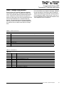
Figure 17. Connecting the THZ2 or TDZ2 in Multidrop Configuration
HART-Based
DCS
(Primary Master)
+
–
TDZ2
–
602.78
ADDR
+PS
1
-PS
1
2
3
2
THZ
DEG C
0
3
4
2 SMART HART
TEMPERATURE
TRANSMITTER
+
4
–
+PS –PS
+
2
TDZ
(HART
Slave)
28
2
THZ
(HART
Slave)
The Interface Solution Experts
2
THZ
(HART
Slave)
HART
Communicator
(HART
Secondary
Master)
THZ 2 & TDZ 2
Programmable Smart HART
Temperature Transmitter and Display
HART Status Information
Each time the THZ2 and TDZ2 generate a response,
frame status information is included in the reply message. The first byte indicates communications errors,
if any. Otherwise, if communication was good, this
byte may indicate the status of the received command
(such as transmitter busy or a command not supported). The second status byte indicates the operational state of the slave device. A properly operating
slave device will have both status bytes set to logic
zero.
The following tables include the common information
that is returned in every response message. However,
they do not detail the transmitter-specific Additional
Status Information that is returned in the data portion
of the response to HART Command 48. You may access the Additional Status Information window via the
View dropdown menu in the tool bar.
Table 6. Communications Errors
Bit 7 = 1
Bit
Description
0
Undefined
1
2
Buffer Overflow
3
4
5
Checksum Error
6
7
Parity Error
This bit is always set when Communication errors occur
Reserved set to zero
Framing Error
Overrun Error
Table 7. Command Errors
Bit 7 = 0
Value
Hex
0
1
0x00
2
3
4
5
6
18
32
64
0x01
0x02
0x03
0x04
0x05
0x06
0x12
0x20
0x40
Description
No command Errors
Undefined Error
Invalid selection
Passed Parameter too large
Passed Parameter too small
Too Few bytes received
Transmitter Specific Command Error
Invalid UOM Code
Transmitter Busy
Command not supported
The Interface Solution Experts
29
THZ 2 & TDZ 2
Programmable Smart HART
Temperature Transmitter and Display
Table 8. Device Status Bytes Table
Bit
Type
Description
0
Error
Primary Variable Out of Limits. The process applied to the sensor for the Primary Variable is beyond
the operating limits of the device.
1
Error
Non-Primary Variable Out of Limits. The process applied to a sensor, other than that of the Primary
Variable, is beyond the operating limits of the device. Command #48, Additional Status Information,
may be requried to identify the variable.
2
Error
3
Error
4
Error
5
Error
Cold Start. Power has been removed and reapplied resulting in the reinstallation of the setup information.
The first command to recognize this condition will automatically reset this flag. This flag may also be set
following a Master Reset or a Self Test.
6
Error
Configuration Changed. A write or set command has been executed.
7
Error
Device Malfunction. A hardware error or failure has been detected by the device. Further information
may be available through Command #48, Additional Status Information.
Analog Output Saturated. The analog and digital outputs for the Primary Variable are beyond their limits
and no longer represent the true applied process.
Analog Output Current Fixed. The analog and digital outputs for the Primary Variable are held at
the requested value. They will not respond to the applied process.
Additional Status Available. More status information is available than can be returned in the Field Device
Status. Command #48, Additional Status Information may be required to identify the variable.
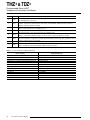
Table 9. Process Variable Error Displayed Messages
Error Condition
Displayed Message
Hardware failure
ERROR HWARE
EEPROM failure
Calibration data bad
Configuration or calibration data checksum mismatch
ERROR EEROM
ERROR CALIB
ERROR CKSUM
EEPROM blank
Process variable out of range (< -99999 or > +99999)
ERROR BLANK
ERROR RANGE
Maths division by zero error
Configuration information bad
ERROR DZERO
ERROR CONFG
Software watchdog failure
RJC Broken
Input saturation condition
ERROR SWARE
RJC BROKE
ERROR INSAT
Front-end comms error condition
Other or combination of errors
ERROR F END
ERROR
30
The Interface Solution Experts
THZ 2 & TDZ 2
Programmable Smart HART
Temperature Transmitter and Display
HART Command 48
The Additional Status Information section in the View
dropdown menu returns five additional HARTstatus information bytes in response to HART Command 48–
Read Additional HART Status Information.
The five data bytes are described in Table 10.
Table 10. HART Command 48 Data Bytes
Status Byte
0
1
2
3
4
5
Status
Word Bit
0
1
2
3
4
Type
Error
Error
Error
Error
Error
Configuration data error
Calibration data error
EEPROM blank
EEPROM failure
Division by zero error
5
6
Error
Error
RJC Broken
Software watchdog failure
7
Error
COP watchdog failure
0
Error
Sensor wire 1 broken
1
Error
Sensor wire 2 broken
2
3
Error
Status
Sensor wire 3 broken
Sensor wires broken
4
5
Status
Status
Out of range error
Input Saturation
6
7
Status
Error
Busy / Calibration, trimming active
Configuration data area checksum error
0
1
2
3
4-7
0-7
0-7
0-7
Error
Error
Error
Error
Not used
Not used
Not used
Not used
Description
Calibration data area checksum error
ADC Error
Bad custom curve
Front-end / Back-end communications failure
Set to zero
Set to zero
Set to zero
Set to zero
The Interface Solution Experts
31
THZ 2 & TDZ 2
Programmable Smart HART
Temperature Transmitter and Display
Installation
Installation consists of physically mounting the unit
and completing the electrical connections.
Mounting the THZ2 or TDZ2
The THZ2 HPP fits inside a 30-35mm connection head
(such as the LH1) using captive mounting screws.
The THZ DIN2 can be mounted on standard DIN
mounting rails. The TDZ2 HP can be mounted with
rails, flanges, or in one of our larger housings, such as
the D-BOX or BH.
Making the Electrical Connections
The connections for the various inputs are shown in
Figures 7 and 8. The figure shows a single transmitter. If you are using multiple units, connect them using the connections shown in Figure 17.
In multi-drop networks, the unit’s receiving device is
normally a HART-communicating control system
acting as the HART Primary Master. The control system uses each transmitter’s individual address to
access real-time process data, sensor diagnostics and
THZ2 or TDZ2 diagnostic data. The address is also
used to locate the appropriate unit, to initiate configuration and to calibrate. A HART communicator, acting
as the HART Secondary Master, can be used to simultaneously access information from, or transmit
configuration information to the transmitter from anywhere along the HART digital link.
Make sure that the total loop resistance is at least
250 ohms so that the 4-20mA signal containing the
HART protocol is not shorted. If loop resistance is
less than 250 ohms, add a resistor.
Recommended Ground Wiring
Practices
Moore Industries recommends the following ground
wiring practices:
• Any Moore Industries product in a metal case or
housing should be grounded.
• The protective earth conductor must be
connected to a system safety earth ground before
making any other connections.
32
The Interface Solution Experts
• All input signals to, and output signals from,
Moore Industries’ products should be wired using
a shielded, twisted pair technique. Shields are to
be connected to an earth or safety ground at the
unit itself.
• The maximum length of unshielded input
and/or output signal wiring should be
two inches.
Switches and Circuit Breakers
A switch or circuit breaker must be wired in series with
the AC power conductors. The switch or circuit
breaker used must be located within three meters of
the unit.
WARNING:
Terminals on this unit may be connected to
hazardous voltages. Before making ANY
connections to this unit, ALL hazardous voltages
must be de-energized.
The circuit breaker or switch will only remove power to
the unit, hazardous voltages may still be connected to
other terminals on the unit.
Installation Category
All of Moore Industries’ terminals are rated CAT II, except those with the -RF option. These terminals are
rated CAT I.
Equipment Ratings
The THZ2 and TDZ2 do not generate hazardous voltages, rather, they accommodate a temperature input,
and generate a low voltage current output. Products
connected to the THZ2 or TDZ2 should be designed to
receive these inputs.
Supply Wiring
All power connections should be made with the proper
wire.
The end of each conductor should be stripped no more
than 8mm (0.31 in). The end of the stripped wire
should be tinned with solder, or inserted into a ferrule
and crimped before being placed into a terminal block.
Conductors connected to screw-type connections
should have a ring-lug or spade-lug crimped onto the
wire end.
THZ 2 & TDZ 2
Programmable Smart HART
Temperature Transmitter and Display
CE Conformity
Digital Signal
Installation of any Moore Industries’ products that
carry CE certification (Commission Electrotechnique)
must adhere to the guidelines in Recommended
Ground Wiring Practices in order to meet the requirements set forth in applicable EMC (Electromagnetic
Compatibility) directives 89/336/EEC, EN 61326. Consult the factory for the most current information on
products that have been CE certified.
One of the advantages of the HART protocol is that
the digital information is conveyed by the same wires
used to output the 4-20mA signal. After being polled
by the master, the THZ2 or TDZ2 responds to the inquiry by modulating the 4-20mA current 0.5mA above
or below the output signal. 1200 Hz represents 1 and
2200 Hz represents 0.
Operation
Once programmed, calibrated, installed and supplied
with the correct power, THZ2 and TDZ2 transmitters
begin to operate immediately. Depending upon environmental conditions, they can be expected to operate
unattended for extended periods of time.
Communication Speed and Format
The speed of the HART transmission is 1200 bps.
The time delay between a master initiating a request
for data from a slave and the slave receiving and acknowledging the request depends upon which command is issued. Generally, a master can poll a slave
2-3 times per second.
The byte structure of the HART signal is:
HART Protocol
1 Start Bit, 8 Data Bits, 1 Odd Parity Bit, 1 Stop Bit.
This section of the manual gives an overview of the
HART format used by THZ2 and TDZ2 modules during
operation. Use the information in this section to process the data provided by the module(s) during operation. For more information on the HART protocol,
contact the HART Foundation at:
Maintenance
HART Communication Foundation
9390 Research Blvd., Suite I-350
Austin, TX 78759-6540
USA
Phone: (512) 794-0369
Fax: (512) 794-3904
www.hartcomm.org
Device Types
To implement two-way communication between the
THZ2 and the device being used to configure it or receive its information, the THZ2 and TDZ2 operate in a
HART Master/Slave structure. The THZ2 or TDZ2 is
the Slave (or slaves in a multidrop network).
Moore Industries suggests a quick check for terminal
tightness and general unit condition every 6-8 months.
Always adhere to any site requirements for programmed maintenance.
Customer Support
If service assistance is ever required for an device in
your application, refer to the back cover of this manual
for the telephone numbers to Moore Industries’ customer service department.
If possible, make a note of the model number of the
unit before calling. For fastest assistance, have the
following information available: serial number, the job
number and purchase order number under which it was
shipped
There can be two Masters per system: a Primary
Master and a Secondary Master. Masters are typically
either a HART Hand-Held Communicator or a HARTbased control system.
In many applications, the Primary Master is a HART
Hand-Held Communicator. The communicator is used
solely as a configuration tool to set up the transmitter,
periodically view its real-time process measurement,
or view its operating and diagnostic information from a
loop termination point.
The Interface Solution Experts
33
THZ 2 & TDZ 2
Programmable Smart HART
Temperature Transmitter and Display
II. Type N (Ex n) Applications (Zone 2)
Intrinsically-Safe
Applications
2
2
This page contains information for the THZ and TDZ
instruments when used within an intrinsically-safe system.
The diagram on the following page must be used for
units that are to operate in areas requiring intrinsicallysafe instrumentation.
Refer to the Special Conditions outlined below before
proceeding with installation.
1. As Category 3 equipment, the Models THZ2 and
TDZ2 Temperature Transmitters shall be installed in an
enclosure which maintains an ingress protection of
IP54 and meets the enclosure requirements of
EN60079-0 and EN60079-15.
2. The Models THZ2 & TDZ2 Temperature Transmitters shall contain external transient protection to prevent the supply voltage from exceeding 46.2V
including tolerance.
3. Wiring must be rated for 85°C.
Special Conditions of Use
The following instructions must be adhered to when
the THZ2 and TDZ2 are used in hazardous ‘Classified’
locations and potentially explosive atmospheres.
I. Intrinsically Safe (Ex ia)
Applications (Zones 0 and 1)
1. The Models THZ2 and TDZ2 Temperature Transmitters shall be installed in a final enclosure rated for a
minimum of IP20.
2. For Zone 0 installations, the final enclosure shall
not contain more than 10% in total of aluminum, magnesium, titanium and zirconium, or 7.5% in total of
magnesium, titanium and zirconium.
3. For Zone 1 installations, the final enclosure shall
not contain 7.5% in total of magnesium.
4. Wiring must be rated for 85°C.
Safety Concerns
For your safety, read the following information carefully before proceeding with installation.
WARNING: EXPLOSION HAZARD – FOR
DIVISION 2 HAZARDOUS LOCATIONS. DO NOT
DISCONNECT EQUIPMENT WHEN A FLAMMABLE
ATMOSPHERE IS PRESENT.
WARNING: SUBSTITUTION OF COMPONENTS IS
NOT ALLOWED AS IT MAY IMPAIR THE
INTRINSIC SAFETY (ZONES 0 & 1, DIVISION 1)
OF THE UNIT AND/OR THE NON-INCENDIVE/
TYPE N (DIVISION 2, ZONE 2) CIRCUIT. DO NOT
OPEN THE UNIT WHEN EITHER ENERGIZED OR
WHEN AN EXPLOSIVE GAS/DUST ATMOSPHERE
IS PRESENT. DISCONNECT POWER BEFORE
SERVICING. READ AND UNDERSTAND THE
MANUFACTURER’S INSTALLATION AND
OPERATING PROCEDURES, AND ADHERE TO
ALL APPLICABLE ELECTRICAL CODES, SAFETY
INSTRUCTIONS AND REGULATIONS.
AVERTISSEMENT – RISQUE D’EXPLOSION. NE
PAS DEBRANCHER TANT QUE LE CIRCUIT EST
SOUS TENSION, A MOINS QU’IL NE S’ AGISSE
D’UN EMPLACEMENT NON DANGEREUX.
WARNING: END-USER MUST MARK EITHER
CHECKER BOX ON THE INSTRUMENT ID LABEL
WITH THE INTENDED APPLICATION –
INTRINSICALLY SAFE OR TYPE N / NONINCENDIVE.
34
The Interface Solution Experts
DRAWN
For Hazardous 'Classified' Locations
1
3
COM
1
2
4
3
II 1G Ex ia IIC,
II 3G Ex nA IIC, (T4 / T5 / T6)*
IECEx: Ex ia IIC, Ex nA IIC, (T4 / T5/ T6)*
*T. Codes: T4@85°C (TDZ2), T5@85°C/T6@60°C (THZ2)
Operating Temperature Range: -40°C ≤ Tamb. ≤ +85°C
ATEX:
4
3
1
2
-PS
THZ2
+PS
COM
A
CB
APPROVAL
}
0518
Input device must be"Agency-Approved" per
application area (CSA, FM, ISSeP, KEMA,
LCIE, UL, TestSafe, SIRA, TUV, etc....).
{
I.S. Entity Parameters
(Power/Loop, +PS & -PS):
Vmax or Ui = 30 VDC
Imax or Ii = 110 mA
Pmax or Pi = 0.825 W
Ci = 5.83 nF
Li = 0 H
Ca or Co ≥ Ci + Ccable
La or Lo ≥ Li + Lcable
Vmax or Ui ≥ Voc or Vt
Imax or Ii ≥ Isc or It
For areas classified with "dust-hazard" (Class II/III, Division 1,
Groups E, F & G), these devices must be mounted in approved
protective enclosures that are rated and suitable for use in the
designated application areas. Use +85°C rated electrical wire.
IECEx
Ca or Co = 20 µF, Gr. A/B
Ca or Co = 498 µF, Gr. C/D
Ca or Co = 998 µF, Gr. D
La or Lo = 25 mH, Gr. A/B
La or Lo = 100 mH, Gr. C/D
La or Lo = 200 mH, Gr. D
Barrier-to-Xmitter Cable:
≤ 3,575 ft, 214.5 nF, Gr. A/B
≤ 103,166 ft, 6.19 µF, Gr. C/D
≤ 423,166 ft, 25.39 µF, Gr. D
BY
06/07 G.E.
DATE
REVISION
NOTICE RE PROPRIETARY INFORMATION: This drawing and the information contained herein are the proprietary property of Moore IndustriesInternational, Inc. (MII) and should not be reproduced or disclosed to any
third party without the written consent of an authorized officer of MII.
THZ2 [HPP]: 4-20mA PC-Programmable
Smart HART Temperature Transmitter
Sensor Type - mA, mV,
POT, RTD, Ω, T/C:
Voc or Vt = 6.51 VDC
Isc or It = 35.39 mA
Po = 57.6 mW
Hazardous 'Classified' Locations/Areas
US (NEC 500/505) / Canada (C22.2-1010.1)
Intrinsically Safe & Non-Incendive
Class I, Zone 0, AEx ia IIC, (T4 / T5 / T6)*
Class I; Divisions 1 & 2; Groups A-D
(3)
+PS
-PS
–PS
TDZ2
TDZ2 [HP]: 4-20 mA PC-Programmable Smart
HART Temperature Transmitter w/ Display
+PS
100-100-71
INITIAL RELEASE
REVISED BY
DRAWING NUMBER
Caution: The 'COM' Port Must Not Be Used In Hazardous 'Classified' Locations.
NONE
Field Installation Diagram:
TDZ2 [HP] & THZ2 [HPP]
Intrinsically Safe System
TITLE
CONTROL DRAWING
CATEGORY
(1)- Apparatus which is unspecified except that it must not be supplied from, or contain under normal or abnormal conditions a source of potential with respect to earth in excess of 250 VRMS or 250 VDC
which is considered to be the Safe Area's maximum voltage.
(2)- The Barrier or other Associated Apparatus must be agency-approved (CSA/FM/SAA/SIRA/UL, etc..) per the "specific" installation area for Intrinsically Safe connections (Zones 0/1, Class I / Div. 1).
US barriers for USA, Canadian barriers for Canada, ATEX bariers for Europe, IECEx barriers where applicable. The output voltage (Voc, Vt or Vo) must not exceed 30 VDC & the output
current (Isc, It or Io) must not exceed 110 mA. Also, it must be installed per the manufacturer's guidelines. A Shunt Zener Barrier is NOT required for Non-Incendive / Type N installations.
(3)- The combined Capacitance and Inductance of the inter-connecting cables of the device (hazardous area) must not exceed the values indicated on the Associated Apparatus (safe area).
4- For US applications, installation must be in accordance to 'ANSI-P12.6' (Installation of I.S. Systems for Hazardous 'Classified' Locations) and the National Electric Code 'ANSI/NFPA 70'. Also, a
dust-tight conduit seal must be used when installed in Class II and Class III environments. For applications in Canada, adhere to the 'Canadian Electric Code C22.1' most current publication on I.S.
installationguidelines. For CENELEC/ATEX and IECEx applications, adhere to 'EN 60079-14:1997' or any equivalent IEC-based, most current and pertaining publication on I.S. installation guidelines.
5- Warning: Substitution of components is NOT allowed as it may impair the Intrinsic Safety of the unit and/or the Non-Incendive circuit. DO NOT open the unit when either energized or if an explosive
gas/dust atmosphere is present. Disconnect power before servicing. Also read, understand and adhere to the manufacturer's installation and operating procedures.
6- The maximum power parameters of the COM port (to be used only in safe/non-hazardous areas) are: Vmax = 3.0 VDC, Imax = 300 µA, Pmax = 240 µW.
Notes:
(2)
(1)
Ground Path
Resistance Must
Not Exceed 1Ω
Barrier or other
Associated
Apparatus
Unspecified
Apparatus
Non-Hazardous (Safe) Area
CERTIFIED PRODUCT
This is a controlled 'Related' or 'Schedule'
drawing. No modifications are permitted
without the notification and final approval
of the Certification Engineer (related dwgs.)
or the Certifying Agency (schedule dwgs.).
06/07
Gus H. Elias 06/07
S.K.
Gus H. Elias 06/07
CHECKED
DECIMALS = ±inch/mm
= ±.1 /2.54
.X
= ±.03 /0.76 ENGINEER
.XX
= ±.010/0.25
.XXX
HOLES:=+.003-.002/+.08-.05 SCALE
ANGLES: = ± 30'
(UNLESS NOTED)
TOLERANCES
DO NOT SCALE DRAWING
Refer to the Safety Concerns section on the previous page before continuing with installation.
DRAWN
1/1
CERTIFIED PRODUCT
This is a controlled 'Related' or 'Schedule'
drawing. No modifications are permitted
without the notification and approval of
the Certification Engineer (related dwgs.)
or the Certifying Agency (schedule dwgs.).
1.532
REF
SERIAL:
YEAR:
TAG:
*Explosion Hazard: install per IS Dwg. 100-100-71.
Do not disconnect in hazardous locations. -2207A
0518
CA 91343 U.S.A.
FM06ATEX0011X,FM06ATEX0030X,FMG07.0002X:
4-20mA: I.S. (12-30dc)*, N.I./TypeN (12-42dc)
Class I, Zone 0, AEx ia IIC, T4@85°C.
Class I, Divisions 1 & 2, Groups A-D.
II 1G Ex ia IIC T4
/
II 3G Ex nA IIC T4.
Ex ia IIC T4 / Ex nA IIC T4. Use 85°C rated wire.
MODEL:
1.712
REF
Intrinsically Safe: 12-30Vdc
Gen. Loc., N.I., Type N: 12-42Vdc
ATEX, cFMus, IECEx.
TDZ2 [HP]: 4-20mA HART Temp. X-mitter
COMPUTERIZED LABEL
TITLE
REAR ID LABEL
CATEGORY
200-251-2207
BY
06/07 G.E.
DATE
CB
APPROVAL
A
REVISION
End-user must mark the checker box
with the intended application:
Intrinsically Safe or
Type N / Non-Incendive.
0.052 R.
REF
NOTICE RE PROPRIETARY INFORMATION: This drawing and the information
contained herein are the proprietary property of Moore Industries-International,
Inc. (MII) and should not be reproduced or disclosed to any third party without
the written consent of an authorized officer of MII.
INITIAL RELEASE
REVISED BY
DRAWING NUMBER
1. TO PRINT THIS LABEL: JOB SPECIFIC MODEL, SERIAL, YEAR AND TAG NUMBERS
WILL BE DOWNLOADED FROM THE MENTOR DATA FILE AND PRINTED ALONG
WITH THE FIXED TEXT AND GRAPHICS (SUPPLIED BY THE LEGI 93 DATA FILE)
TO CREATE THE FINISHED LABEL.
2. THE FIXED TEXT AND GRAPHIC FIELDS FOR THIS LABEL ARE STORED UNDER
NO. 200-251-2207 IN THE LEGI 93 LABEL MACHINE COMPUTER HARD DISK.
3. MATERIAL: .002 SILVER, IDENTIPLATE (MII P/N 200-301-00) DIE CUT AS SHOWN
ABOVE. REFER TO LABEL SPEC. DRAWING 200-301-00.
NOTES:
06/07
Gus H. Elias 06/07
S.K.
Gus H. Elias 06/07
DECIMALS = ±inch/mm CHECKED
= ±.1 /2.54
.X
= ±.03 /0.76 ENGINEER
.XX
= ±.010/0.25
.XXX
HOLES:=+.003-.002/+.08-.05 SCALE
ANGLES: = ± 30'
(UNLESS NOTED)
TOLERANCES
DO NOT SCALE DRAWING
DRAWN
1/1
.720
CA 91343 USA
TAG:
SERIAL:
MODEL:
'Cut Line'
FM06ATEX0011X/FMG07.0002X.
I.S. (12-30dc)*,N.I. (12-42dc)**:
Class I, Div. 1 & 2, Gr. A-D.
Class I, Zone 0, AEx ia IIC.
-2208A
II 1G Ex ia IIC / Ex ia IIC.
II 3G Ex nA IIC / Ex nA IIC.
T6@60C/T5@85C, 4-20mA.
0518 *100-100-71,**FM06ATEX0030X.
2.250
Intrinsically Safe: 12-30Vdc
Gen. Loc, N.I., Type N: 12-42Vdc
ATEX, cFMus, IECEx.
THZ2 [HPP]: 4-20mA HART Temp. X-mitter
COMPUTERIZED LABEL
TITLE
ID LABEL
CATEGORY
200-251-2208
BY
06/07 G.E.
DATE
CB
APPROVAL
A
REVISION
End-user must mark the checker box
with the intended application:
Intrinsically Safe or
Type N / Non-Incendive.
NOTICE RE PROPRIETARY INFORMATION: This drawing and the information
contained herein are the proprietary property of Moore Industries-International,
Inc. (MII) and should not be reproduced or disclosed to any third party without
the written consent of an authorized officer of MII.
INITIAL RELEASE
REVISED BY
DRAWING NUMBER
1. TO PRINT THIS LABEL: JOB SPECIFIC MODEL, SERIAL, AND TAG NUMBERS WILL BE DOWNLOADED FROM THE MENTOR
DATA FILE AND PRINTED ALONG WITH THE FIXED TEXT AND GRAPHICS (SUPPLIED BY THE LEGI 93 DATA FILE) TO
CREATE THE FINISHED LABEL.
2. THE FIXED TEXT AND GRAPHIC FIELDS FOR THIS LABEL ARE STORED UNDER NO. 200-251-2208 IN THE LEGI 93 LABEL
MACHINE COMPUTER HARD DISK.
3. MATERIAL: .002 SILVER, IDENTIPLATE (MII P/N 200-304-00) DIE CUT AS SHOWN ABOVE. REFER TO LABEL SPEC. DRAWING
200-304-00.
NOTES:
This is a controlled 'Related' or 'Schedule'
drawing. No modifications are permitted
without the notification and final approval
of the Certification Engineer (related dwgs.)
or the Certifying Agency (schedule dwgs.).
CERTIFIED PRODUCT
06/07
Gus H. Elias 06/07
S.K.
Gus H. Elias 06/07
DECIMALS = ±inch/mm CHECKED
= ±.1 /2.54
.X
= ±.03 /0.76 ENGINEER
.XX
= ±.010/0.25
.XXX
HOLES:=+.003-.002/+.08-.05 SCALE
ANGLES: = ± 30'
(UNLESS NOTED)
TOLERANCES
DO NOT SCALE DRAWING
Declaration of Conformity
EMC Directive 89/336/EEC
• Manufacturer’s Name:
• Manufacturer’s Address:
Moore Industries-International, Inc.
16650 Schoenborn Street
North Hills, CA 91343-6196
USA
We herewith attest that the product detailed below meets EMC specifications defined by
EN61326-1, Electromagnetic Compatibility Requirements for Electrical Equipment for Control Use.
TDZ2 - HP; THZ2 - HPP; THZ2 - DIN
• Product Name:
MODEL
• Model Number(s): same as above
/
INPUT /
OUTPUT
*
*
/
POWER
*
/
OPTIONS /
HOUSING
*
*
* Indicates any input, output, power, option and housing as stated in the product data sheet.
• Supplementary Information:
None.
October 2005
Date
Fred Adt
Quality Assurance Director
Robert Stockham
Moore Industries-Europe General Mgr.
European Contact: Your Local Moore Industries Sales and Service Office
United States • [email protected]
Tel: (818) 894-7111 • FAX: (818) 891-2816
Australia • [email protected]
Tel: (02) 8536-7200 • FAX: (02) 9525-7296
Belgium • [email protected]
Tel: 03/448.10.18 • FAX: 03/440.17.97
The Netherlands • [email protected]
Tel: (0)344-617971 • FAX: (0)344-615920
China • [email protected]
Tel: 86-21-62491499 • FAX: 86-21-62490635
United Kingdom • [email protected]
Tel: 01293 514488 • FAX: 01293 536852
RETURN PROCEDURES
To return equipment to Moore Industries for repair, follow these four steps:
1. Call Moore Industries and request a Returned Material Authorization (RMA) number.
Warranty Repair –
If you are unsure if your unit is still under warranty, we can use the unit’s serial number
to verify the warranty status for you over the phone. Be sure to include the RMA
number on all documentation.
Non-Warranty Repair –
If your unit is out of warranty, be prepared to give us a Purchase Order number when
you call. In most cases, we will be able to quote you the repair costs at that time.
The repair price you are quoted will be a “Not To Exceed” price, which means that the
actual repair costs may be less than the quote. Be sure to include the RMA number on
all documentation.
2. Provide us with the following documentation:
a) A note listing the symptoms that indicate the unit needs repair
b) Complete shipping information for return of the equipment after repair
c) The name and phone number of the person to contact if questions arise at the factory
3. Use sufficient packing material and carefully pack the equipment in a sturdy shipping
container.
4. Ship the equipment to the Moore Industries location nearest you.
The returned equipment will be inspected and tested at the factory. A Moore Industries
representative will contact the person designated on your documentation if more information is
needed. The repaired equipment, or its replacement, will be returned to you in accordance with
the shipping instructions furnished in your documentation.
WARRANTY DISCLAIMER
THE COMPANY MAKES NO EXPRESS, IMPLIED OR STATUTORY WARRANTIES (INCLUDING ANY WARRANTY OF MERCHANTABILITY OR OF FITNESS
FOR A PARTICULAR PURPOSE) WITH RESPECT TO ANY GOODS OR SERVICES SOLD BY THE COMPANY. THE COMPANY DISCLAIMS ALL WARRANTIES ARISING FROM ANY COURSE OF DEALING OR TRADE USAGE, AND
ANY BUYER OF GOODS OR SERVICES FROM THE COMPANY ACKNOWLEDGES THAT THERE ARE NO WARRANTIES IMPLIED BY CUSTOM OR
USAGE IN THE TRADE OF THE BUYER AND OF THE COMPANY, AND THAT
ANY PRIOR DEALINGS OF THE BUYER WITH THE COMPANY DO NOT IMPLY THAT THE COMPANY WARRANTS THE GOODS OR SERVICES IN ANY
WAY.
ANY BUYER OF GOODS OR SERVICES FROM THE COMPANY AGREES
WITH THE COMPANY THAT THE SOLE AND EXCLUSIVE REMEDIES FOR
BREACH OF ANY WARRANTY CONCERNING THE GOODS OR SERVICES
SHALL BE FOR THE COMPANY, AT ITS OPTION, TO REPAIR OR REPLACE
THE GOODS OR SERVICES OR REFUND THE PURCHASE PRICE. THE
COMPANY SHALL IN NO EVENT BE LIABLE FOR ANY CONSEQUENTIAL OR
INCIDENTAL DAMAGES EVEN IF THE COMPANY FAILS IN ANY ATTEMPT
TO REMEDY DEFECTS IN THE GOODS OR SERVICES , BUT IN SUCH CASE
THE BUYER SHALL BE ENTITLED TO NO MORE THAN A REFUND OF ALL
MONIES PAID TO THE COMPANY BY THE BUYER FOR PURCHASE OF THE
GOODS OR SERVICES.
United States • [email protected]
Tel: (818) 894-7111 • FAX: (818) 891-2816
Australia • [email protected]
Tel: (02) 8536-7200 • FAX: (02) 9525-7296
© 2007 Moore Industries-International, Inc.
ANY CAUSE OF ACTION FOR BREACH OF ANY WARRANTY BY THE
COMPANY SHALL BE BARRED UNLESS THE COMPANY RECEIVES
FROM THE BUYER A WRITTEN NOTICE OF THE ALLEGED DEFECT OR
BREACH WITHIN TEN DAYS FROM THE EARLIEST DATE ON WHICH THE
BUYER COULD REASONABLY HAVE DISCOVERED THE ALLEGED DEFECT OR BREACH, AND NO ACTION FOR THE BREACH OF ANY WARRANTY SHALL BE COMMENCED BY THE BUYER ANY LATER THAN
TWELVE MONTHS FROM THE EARLIEST DATE ON WHICH THE BUYER
COULD REASONABLY HAVE DISCOVERED THE ALLEGED DEFECT OR
BREACH.
RETURN POLICY
For a period of thirty-six (36) months from the date of shipment, and under
normal conditions of use and service, Moore Industries ("The Company") will
at its option replace, repair or refund the purchase price for any of its manufactured products found, upon return to the Company (transportation charges
prepaid and otherwise in accordance with the return procedures established
by The Company), to be defective in material or workmanship. This policy
extends to the original Buyer only and not to Buyer's customers or the users
of Buyer's products, unless Buyer is an engineering contractor in which case
the policy shall extend to Buyer's immediate customer only. This policy shall
not apply if the product has been subject to alteration, misuse, accident, neglect or improper application, installation, or operation. THE COMPANY
SHALL IN NO EVENT BE LIABLE FOR ANY INCIDENTAL OR CONSEQUENTIAL DAMAGES.
Belgium • [email protected]
Tel: 03/448.10.18 • FAX: 03/440.17.97
The Netherlands • [email protected]
Tel: (0)344-617971 • FAX: (0)344-615920
China • [email protected]
Tel: 86-21-62491499 • FAX: 86-21-62490635
United Kingdom • [email protected]
Tel: 01293 514488 • FAX: 01293 536852
Specifications and Information subject to change without notice.
User’s Manual Supplement
Physical Instructions for Installing an
Encapsulated Hockey-Puck (HPP) Instrument
and LH2 Field-Mount Enclosure Apparatus
January 2001
The Physical Instructions Supplement provides
references and additional information for safely installing
and commissioning a Moore Industries’ Hockey-Puck
instrument and LH2 Field-Mount Enclosure Apparatus.
Instrument Labeling and Identification—The fully
assembled apparatus consists of a Moore Industries’
Hockey-Puck unit securely mounted in an LH2
enclosure. Such an apparatus is intended for use in
both indoor and outdoor Hazardous (Classified)
Locations where a degree of protection from windblown
dust and rain, splashing and hose-directed water, and
protection from the formation of ice on the enclosure is
required. A series of selected Moore Industries’ 2-Wire
hockey-puck style units mounted in the LH2 enclosure
(consult factory for a list of the certified instruments) are
certified as an Explosion-Proof and Dust Ignition-Proof
appartus in accordance with Factory Mutual Research
‘3600’ standard (NEC-based) and as Flame-Proof in
accordance with the CENELEC/ATEX Directive 94/9/EC
(IEC-based). For applications intended in North America
and other related areas, the approval classifications are
stated on the externally mounted metal ID Tag to be FM
approved as Explosion-Proof for Class I, Division 1,
Groups A, B, C and D; Dust Ignition-Proof for Class II/III,
Division 1, Groups E, F and G; T6 @ 60°C Maximum
Operating Ambient Temperature. In regards to
protection from Environmental hazards/effects, the
apparatus carries a NEMA Type 4X rating with an
Ingress Protection Code of IP66 as per IEC-529. For
applications intended in Europe and other related areas,
the ID Tag clearly states that the apparatus is certified by
ISSeP to be Flame-Proof and marked as such:
II 2GD EEx d IIC; T6 @ Tamb. (-20°C ≤Tamb.
≤+60°C). The temperature marking for dust atmospheres is up to + 80°C. The maximum power parameters are: Vmax = 42 VDC, Imax = 110 mA and
Pmax = 2W. Also, the tag clearly shows the CE marking
denoting full compliance with the relevant European
Community directives applicable to the Process
Instrumentation Industry. For 2-wire transmitters certified
and intended to be operated as either Intrinsically Safe,
Non-Incendive (Class I, Div. 2) or Type N; the power
parameters are clearly stated on both the Instrument ID
Label and the Apparatus ID Tag. Also, the power
parameters and cabling requirements are stated in the
‘Intrinsically Safe Barrier and Field Installation Diagram’
that is included in the relevant User’s Manuals. This
apparatus is designed in such a way that it: a) does not
give rise to physical injury or other harm due to contact,
b) does not produce excessive surface temperature,
infra-red, electromagnetic, ionizing radiation and, c)
have no non-electrical dangers.
CAUTION
Read, understand and adhere to the manufacturer’s
installation and operating procedures. Substitution of
components may impair the instrument’s Intrinsic Safety
and/or Non-Incendivity. Keep cover tightly closed. Do not
open unit when energized. Do not open unit when either
an explosive gas or dust atmosphere is present. Cable
entry temperature may exceed 70°C. Cabling to be
suitable. Do not allow layers of dust to accumulate on
the surfaces of the equipment. Disconnect power before
servicing.
Contact Information—If you have installation, maintenance, periodic service, warranty questions or emergency repair requirements, please contact the nearest
Moore Industries sales and service office. Contact
information can be found on the back of this Supplement,
in the User’s Manual for the instrument, or at Moore
Industries’ web site: www.miinet.com
User’s Manual—Complete information for an individual
instrument model can be found in the Moore Industries
User’s Manual for that instrument. The manual provides
information for putting the instrument safely into service.
This, where applicable, includes instructions, drawings
and diagrams. The Manual also includes appropriate
Warnings, Cautionary Statements, and Notes.
User’s Manual components, where applicable, include:
Introduction—Brief description of the instrument and its
general application and use.
Specifications—Provides electrical and environmental
conditions under which the instrument is designed to
safely perform.
Ordering Information—Provides a description of the
product model number to assist in verifying that the
instrument received matches the instrument ordered for
the installation.
Calibration and Configuration—Describes how to
accomplish instrument settings and adjustment required
to set up the unit
Installation and Connection—Describes how to install
the instrument and make electrical connections
(including terminal designations). See the back of this
Supplement for additional information on how to install
the hockey-puck instrument into the LH2 enclosure.
Maintenance—Describes recommended maintenance (if
any required) for the instrument. The user should consult
their own maintenance procedures for any site-specific
maintenance procedures (such as scheduled recalibrations) or other maintenance schedules that may
apply to instruments such as those supplied by Moore
Industries.
Troubleshooting—Describes, where applicable,
procedures for correcting any operational difficulties that
may be encountered as a result of improper configuration/calibration or installation of the instrument.
Customer Support—Describes the procedure and
information required to efficiently receive answers to
questions regarding instrument installation, set up, or
operation.
The Interface Solution Experts • www.miinet.com
700-764-00A
User’s Manual Supplement
Physical Instructions for Installing an
Encapsulated Hockey-Puck (HPP) Instrument
and LH2 Field-Mount Enclosure Apparatus
Suitability for the Installation—To determine if a unit’s
area classification approvals are appropriate for a
particular installation, first inspect the classification
labeling on the instrument and/or instrument enclosure
and the “Control Drawing for Installation” found in the
User’s Manual (where applicable). Second, consult the
installation criteria for the approval or electrical standard
agencies governing your location to determine if the
unit’s approvals are suitable for the installation. If the
instrument’s labeling matches the agency criteria and/or
electrical codes for the area, the unit is suitable for the
installation. To determine if the unit’s electrical and
environmental specifications are appropriate for the
installation, consult the “Specifications” table in the
User’s Manual for that instrument. If the instrument’s
electrical and environmental characteristics are within
the expected ambient operating conditions for the
installation, the instrument is suitable for the installation.
CAUTION
If for any reason you are uncertain as to whether the
instrument’s specifications or area classifications meet
the operational or safety requirements for the installation,
consult Moore Industries prior to installation.
Installation of LH Enclosure Apparatus
1. Install the LH2 enclosure onto a surface, temperature
thermowell, or onto a standard 2-inch pipe using the
mounting hardware. Remove the cap from the LH2 by
rotating the cap counter clockwise after unlocking by
rotating the locking screw clockwise.
2. Connect input and output wiring in accordance with the
connection information found in the User’s Manual for
that instrument.
3. Replace the cap to the LH2 by rotating the cap
clockwise. Secure (lock) the cap by rotating the
locking screw counterclockwise.
4. Connect a ground wire between the ground screw on
the LH2 enclosure to an appropriate earth ground.
Ground Wire Recommendations
The following ground wiring practices must be followed
to ensure proper performance of the Moore Industries
instrument in any application.
• The maximum allowable length of any unshielded
portion of the input and/or output connections is 2
inches (50.8mm).
See the User’s Manual for the instrument for additional
installation information.
Figure 1. Installation dimensions for LH2 enclosure.
87mm
(3.44 in)
Safety Lock
(LH2 only)
SIDE
Conduit
Entry Port
92mm
(3.61 in)
30mm
(1.2 in)
9mm
(0.35 in)
DIA. 72mm
(DIA. 2.85 in)
FRONT
51mm
(2.0 in)
BOTTOM
M4.0 x 0.7 INSIDE Instrument
Mounting Holes
(4 places)
40mm (1.56 in)
Metal Tag
Instrument
Mounting
Holes
33mm
(3.07 in)
61mm
(2.4 in)
10-32
Mounting
Holes (2)
Ground
Process Connection
1/2-in NPT (N and M models) or
G½ (BSP) (C models)
I.D. 62mm x 19mm Deep
(2.43 in x 0.76 in Deep)
2-INCH PIPE MOUNTING HARDWARE
84mm
(3.30 in)
• Any Moore Industries product in a metal case or
housing must be grounded.
• All input signals to, and output signals from, Moore
Industries’ products should be connected using a
shielded, twisted pair technique. Shields should be
connected to an earth or safety ground at the unit itself.
89mm
(3.5 in)
2-in Pipe Bracket
Mounting Holes (4)
61mm
(2.4 in)
CL
61mm
(2.4 in)
United States • [email protected]
Tel: (818) 894-7111 • FAX: (818) 891-2816
Australia • [email protected]
Tel: (02) 8536-7200 • FAX: (02) 9525-7296
© 2006 Moore Industries-International, Inc.
Belgium • [email protected]
Tel: 03/448.10.18 • FAX: 03/440.17.97
The Netherlands • [email protected]
Tel: (0)344-617971 • FAX: (0)344-615920
China • [email protected]
Tel: 86-21-62491499 • FAX: 86-21-62490635
United Kingdom • [email protected]
Tel: 01293 514488 • FAX: 01293 536852
Specifications and information subject to change without notice.