1
BAIRD
SERVICE MANUAL
MODELS
T.18 – T.20 – T.21
'
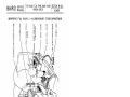
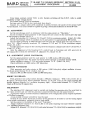
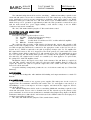
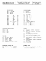
LOUDSPEAKER EXTENSION
MAINS FUSE
5,OOOv TRANSFOR.MER
'02}Jfd S,OOOvCONDENSER
MAINS AERIAL PLUG -
HVR 2 5,OOOv RECTIFIER
BRIGHTNESS POTENT
SOUND AERIAL SOCKET FROM
VISION RECEIVER
ELECTROLYTIC SMOOTHING
CONDENSER
~
.r •. <1
•.
~
---
-.un-
/
2D4A 2N_D DETECTOR 6 AVC RECTIFIER
FIRST 6 SECOND I.F. COILS
1
MAINS LEAD
A-
~
/
OSCILLATOR COIL
VP4B I.F.AMPLlFIER
"-
TH4A FREQUENCY CHANGER
SCALE ASSEMBLY {; PILOT LAMPS - _ _ __
35/6002
",.........
H
R-
':
--,"
H
7
. ;f
~9J1 /1
hall
-~
,. £A~
M
,.
SP4B L.F. AMPLIFIER.
-
_
FLAME LAMP
VOLTAGE SELECTOR PANEL
IW4 RECTIFIER
tn»
Z
o
CRI HEATER RESISTANCE
TAP SET TO 2·5 AMP.
m
-0'0
IV
~O
~Z
wl-I
()
V)
~i"
I»
»()
()"tJ
0:;:tJ
Zm
c~
00
00
V)"tJ
-I
rm
SPARE SOCKET FOR
R.F.AMPLlFIER
TIME·BASE POWER SOCKET
LOUDSPEAKER SOCKET
VISION POWER SOCKET
C.RI HEATER LEADS
»()
5,OOOv ANODE LEAD
c<
»m
Z:;:tJ
:::IV)
o
::;tJ
MAINS TRANSFORMER
PEN B4 OUTPUT VALVE
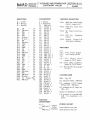
BROADCAST AERIAL COIL
»
O:J
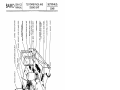
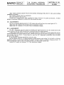
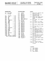
FOCUS COIL ADJUSTING
NUT CONE OF THREE>
AERIAL SOCKET
TO CRI
MODULATION LEAD
FOCUS COIL
LINE COIL SCREEN
A illllll-$d
AC2IHL SYNCH VALVE
FRAME AMPLITUDE CONTROL
~
-..J"~
~ ~/~-,/~
....
..,.<----------,~-
LINE DEFlECTOR-COILS -
V 151 ON UNIT
ANODE CAP
35/6001
POWER LEAD
LINE SCAN TRANSFORMER
UR 1C 20v DIODE
SHIFT CHOKE
GENERATORS
41MP TIME-BASE
2D4A FRAME SYNCH
DIODE
FRAME YOKE
"CATHOVI SOR" CATHODE-RAY TUBE
o
Z
o
~
~
~
~
Z
~
~
CC
d
Z
t::J
........
0'0
SZ
~O
WI-i
Vl
m
()
o
»
m
»
i"'OJ
Vl
~
:::e
()
mm
Z-i
O::I
00
-IV
<-i
Vl.
»
Z
o
co
:-I
om
~
~
-<
o
i
>-
Cl
~
t,J
~
~
~
»()
-.0
c<
Z;:tl
»m
::IVl
o
;a
»
OJ
~
~
~
Z
::l
o
::t
rJ).
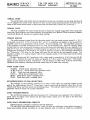
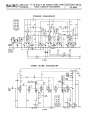
2~D
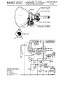
DETECTOR 6 IS.! L.F.AMPLlFIER
EHT
TRANSFORMER
HVR2 5,OOOv RECTIFIER
SOUND TUNING
TONE CONTROL
R.F. TRIMMER (Te I)
I;":?;:~rn
ACITH/1 FREQUENCY CHANGER
~'"''
•.
:/
VP4B I F AMPLIFIER
I.F. TRANSFORMER
TDD4
, ... rc',
PENM OUTPUT
MAINS LEAD
EARTHING SOCKET
VOLTAGE SELECTOR PANfL
CRT HEATER RESISTANC E
TAP SET TO 2·5AMP
MAINS FUSE
TIME-BASE POWER SOCKET
IW4/350 RECTIFIER
CRT HEATER LEAD
VISION POWER SOCKET
ELECTROlYTIC
SMOOTHING CONDENSERS
MAINS TRANSFORMER
~
1-
W
0
-
-
~ Z
0
IIw --I
Vl
m
()
0
»
Z
--17'
Z»
_n
C"
0;;0
0
--I
iv
Vl "
00
c~
Zm
V1
"
11
»m
Z;;o
c<
»n
om
:::IVl
0
;C
»
O:J
BAIRD
SERVICE
MANUAL
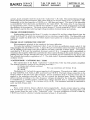
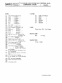
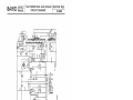
T.IB, T.20, T.21 SCAN
COMPONENTS. T.21 SOUND
CIRCUIT MODIFICATIONS
SECTION 10 (4)
35/4020
LINE DEflECTOR
COILS L3 [& L4
SHIFT COILS L5&L6
FRAME YOKE WINDINGS
L7 (OUTER) & l8 (INNER)
MOD.
VRI (MOUNTED ON
CABINET FRONT IN
SCREENINO CAN)
"........1..
·· .:..... --.... , .
/
~
...
i, ~
I
•
'
• I
TO
L35
P.U.
SOCKETS
ON CHASSIS
This diagram to be used in conjunction with T.IS sound diagram
on Section 12 (3). additional
corn ponents are:
R.32. lOOK lw.
R.33. 250 K 1 w.
5.8.
D.P./C.O. Switch
C. 37 on Section 12 (3) deleted
when used for T.21.
R32
R33
S5/6OI1.
BAIRD
SERVICE
MANUAL
CR. TUBE AND TIME BASE
ADJUSTMENTS T.18, T.20, T.21
SECTION 11 (I)
35/4020
Method and Sequence of Adjustments
Setting up "Cathovisor" C.R. Tube
.
In
HEATER ADJUSTMENT
Insert A.C. ammeter in series with Heater lead and connection socket on base of c.R. Tube and
adjust c.R. Tube Heater resistance on power pack until meter reads 2.5 amp. When making this
adjustment ensure that a short lead capable of carrying the current is used, as .2 amp. can easily
be lost in a bad or frayed connection, a long lead, or a meter with a high resistance, and under
such conditions the reading would appear correct, but C.R.T. heater would be overrun when
meter leads are removed, thereby reducing the life of the tube.
FOCUS ADJUSTMENT
(SPOT)
Ensure that C.R.T. neck is in centre of focus coil by adjusting paxolin locating disc on focus
support bracket.
Reduce Brightness and Contrast to minimum and remove Line and Frame scan generator valves
V.3 and V.6. Insert 7K,4 watt resistor between V.3 anode and earth. (This to obtain focus current
in the focus coil). Carefully turn Brightness up until spot is visible, adjust focus coil adjusting nuts
until spot is in centre of screen. Rotate focus coil round the tube until spot is circular in shape
when set to be approximately 1" in diameter. The spot should remain circular when focus control
is turned and causes the spot to reduce in size through a minimum and then up again to 1" diameter.
It will be found that there are two positions of the focus control where it is possible to obtain a spot
1" diameter, and it is to each of these positions that these adjustments refer. Take great care to keep
the Brightness low to avoid burning the screen. Coil rotation is limited by the connecting wire, but
approximately 180 movement is possible in both clock and anti-clock directions.
0
LINE SCAN FOCUS, AND HORIZONTAL PICTURE ADJUSTMENTS
Remove 7K resistor and replace line scan generator valve V.3. Adjust focus control until a thin
fine horizontal line is traced across the screen. If the focus control will not give sufficient adjustment, vary the line lock control until correct focus is obtained. If the line is not of even width
all over its trace, remove the Line Coil Screen and Flux Link Clamps, readjust Focus and Line Lock
controls as previously explained until line is correctly focussed in the centre, and adjust the line
deflector coils in relation to each other until the line is of equal width overall and horizontal. The
correct position for the coils is when they are equally spaced in relation to each other. It is important
that the line is correctly adjusted horizontally or picture will appear twisted. Reassemble the
Line Coil Screen and Flux Links, taking care not to disturb the position of the coils.
FRAME SCAN ADJUSTMENTS
The Frame deflection is in the vertical direction and it is not necessary to make individual
focus adjustment in this plane, all the adjustments being concerned with the vertical shape of the
picture. If the verticals are twisted in one direction, that is, both sides of picture parallel but not
vertical, the Frame Yoke fixing nuts should be loosened and the whole yoke twisted in the required
direction. The Flux Link clamping screws should be slackened first in order that the line deflector
coils will not be disturbed. Should the limit of the yoke traverse be reached before the necessary
vertical correction is obtained, secure yoke in its optimum position and make further adjustment
by rotation of the line coil screen only (not line deflector coils which must be left in their correct
BAIRD
C.R. TUBE AND TIME BASE
ADJUSTMENTS T.18, T.20, T.21
SERVICE
MANUAL
SECTION 11 (2)
35/4020
horizontal position). These adjustments can best be made by removing modulation and reducing line
amplitude by altering Line Lock control until both sides of the screen are visible inside the mask.
Should trapezoidal distortion be present (i.e., the picture wider at the top than at the bottom or
vice versa) the two pairs of arms on the top of the frame yoke should be adjusted until the distortion
is removed. Finally, adjust Frame Amplitude control until picture height is in correct ratio to
picture width.
PICTURE CENTRING
The picture should always be centred in the mask under transmission picture conditions.
That is during a transmission in which the blackouts are in their correct ratio. It is not advisable
to centre a picture on the cross test bar as the blackouts are too wide and differ from the normal
transmission. Picture centring is accomplished by rotating the three Focus Coil Adjusting Nuts
individually until picture is central in the mask.
FOCUS
The focus control should always be the final time base adjustment, and if it is not possible
to obtain focus by rotation of control, first ensure that the correct mains tap is connected, and then
check whether the focus control is at its maximum or minimum resistance.
Maximum resistance
=
Rotated clockwise from the back.
Minimum resistance
= Rotated anti-clockwise from the back.
If control is at maximum resistance move the focus coil towards the back of the set. If at minimum
resistance move coil towards the screen. (The focus coil needs more current to focus the electron
beam when near the anode or gun, and less current when nearer to the screen. Focus control is
a Variable resistance which takes more current through the coil when resistance is lowest).
Picture must now be re-centred as described, if this adjustment is made.
SYNCHRONISING
When setting lock controls do so with low picture contrast as this is the worst receiving
condition and synchs. will hold over the minimum to maximum contrast range.
Frame Lock should be set so that the picture locks when running upward.
Line Lock should be set in a hard lock position, which may be recognised by the whole picture
moving from right to left when coming into the correct lock position.
BAIRD
SERVICE
MANUAL
T.IS AND T.21 SOUND RECEIVER
ALIGNMENT PROCEDURE
SECTION 11 (3)
35/4020
Turn vision contrast control V.RI to left, thereby switching off the E.H.T. volts to avoid
possibility of high voltage shocks.
Set volume control V.RI to maximum.
Set tone control V.R2 to low (anti-clock from front).
Connect A.C. output meter (with condenser in series) between the anode of the output valve
V.S and chassis. The meter should be capable of giving a reasonable deflection at about 20 volts.
I.F. ALIGNMENT
Set the wavechange switch to television with the scale pointer on "Television."
Set the modulated signal generator to 2.5 megacycles and connect to the control grid (top cap)
of the frequency changer valve V.I.
Adjust the television LF. trimmers T.C.12 and T.C.IS for maximum output. (Coils L.2I, L.24.)
Set the wavechange switch to medium waves and pointer to approximately 300 metres.
Set the signal generator to 465 kilocycles and feed into the control grid (top cap) of the LF.
valve V.2. Adjust carefully broadcast I.F. trimmers T.C.I3 and T.C.I4 for maximum output.
(Coils L.22, L.23.)
Transfer generator output to the control grid of the frequency changer and trim T.C.6 and T.e.7.
(Coils L.I7, L.IS.)
After the alignment of the broadcast I.F.'s switch back to Television and with generator at
2.5 megacycles re-check the television LF. alignment T.C.I2 and T.C.IS.
R.F. ALIGNMENT (LONG WAVEBAND)
Set the signal generator and the scale pointer to 1,300 metres (230 kilo~ycles).
Feed the generator into the aerial and earth sockets through a standard dummy aerial.
Adjust oscillator trimmer T.C.lO and aerial trimmer T.C.3. (Coils L.I6, L.6.)
Check calibration at I,SOO metres (167 kilocycles).
MEDIUM WAVEBAND
With generator and scale pointer at 200 metres (1,500 kilocycles) adjust oscillator trimmer
T.C.9 and aerial trimmer T.C.2. (Coils L.I4, L.4.)
Check at 300 and 500 metres (1,000 and 600 kilocycles).
SHORT WAVEBAND
Feed generator into aerial socket through a 400 ohm resistance. With scale pointer set to
20 metres (15 megacycles) adjust oscillator trimmer T.C.S (Coil L.12) on the peak requiring the
smaller trimmer capacity (i.e., oscillator frequency high). Adjust aerial trimmer T.C.I (Coil L.2)
Check at 50 metres (6 megacycles).
TELEVISION
The television RF. alignment must be carried out feeding the generator into the aerial lead to
the vision receiver and not with the generator connected directly into the sound receiver.
A generator with an accurate frequency calibration at 41.5 megacycles and an output impedance
of 75 ohms is essential.
A non-metallic trimmer screwdriver must be used.
If there be any doubt about the accuracy of the generator it is better to use the tuning signal
of an actual transmission, preferably from a weak aerial.
Set the pointer in the middle of the word "Television."
Adjust oscillator trimmer T.C.1 (Coil L.20) on the peak requiring the larger trimmer capacity
(i.e., oscillator frequency low).
Adjust RF. trimmer T.C.S (Coil L.lO) and aerial trimmer T.CA (Coil L.S) for maximum output.
BAIRD
SERVICE
MANUAL
T. 20 SOUND RECEIVER
ALIGNMENT PROCEDURE
SECTION 11 (4)
35/4020
Turn vision contrast control V.R3 to left thereby switching off the E.H.T. volts and avoiding
possibility of shocks.
Set volume control V.RI to maximum.
Set tone control V.R2 to low.
Connect A.C. output meter, with condenser in series, between V.4 anode and chassis. A meter
giving a reasonable deflection at about 20 volts should be used.
I.F. ALIGNMENT
Set the modulated signal generator to 2.5 megacycles and feed into the control grid of V.I.
Adjust the I.F. trimmer T .C.3 (Coil L.3) for maximum output.
Adjust the I.F. trimmer T.C.6 (Coil L.6) for maximum output.
R.F. ALIGNMENT
The RF. alignment must be carried out feeding the signal generator into the aerial lead to the
vision receiver, and not with the generator connected into the sound receiver.
A signal generator with an accurate and stable frequency calibration at 41.5 megacycles and an
output impedance of 75 ohms must be used. Should there be any doubt about the generator accuracy
it is advised that the B.B.C. Tuning Signal be used for RF. alignment, preferably from an aerial
giving a weak signal.
A non-metallic trimmer screwdriver must be used.
Set the tuning control T.C.5 approximately at half capacity and adjust T.C.2 (Coil L.4, L.5) for
maximum output, on the peak requiring the larger trimmer capacity (oscillator frequency Iow). It
may be found that there is only one peak position, if so this is the correct one.
Adjust RF. aerial coil trimmer T.C.I for maximum output.
BAIRD SERVICE
MANUAL
T.IS, T.20 AND T.21
CIRCUIT SUMMARY
SECTION 11 (5)
35/4020
AERIAL FEED
The aerial feeder cable which must be terminated in the non-reversible two-pin plug (Section 13
(1) ) is plugged into aerial socket (Section 10 (2) ) and the sound aerial plug from the vision unit is
taken to the sound aerial socket on the power pack and sound unit (Section 10 (1) and (3) ).
VISION UNIT
The unit comprises two tuned radio frequency band-pass coupled stages with three megacycle
band-pass, diode detector and video amplifier, incorporating three Mullard TSE4 secondary emission
valves and Mazda D1 special low capacity diode rectifier.
VISION SIGNAL
The radio frequency signal from the television aerial is fed via sound rejector circuit L.l, V.C.1
to the grid circuit L.2. V.C.2, of the first RF. valve V.I, amplified and applied to the second RF.
amplifier valve V.2 via band-pass coils L.3.and L. 10 (L.8 coupling coil). The amplified output of
V.2 is applied via similar band-pass coils L.ll, L.lS (L.I2 coupling coil), into low capacity diode
rectifier and the video frequencies developed across the diode load resistance R19 are applied to the
grid of VA via L.I4. Amplification at video frequency is given by V.4. Positive picture modulation
voltages are developed at the anode of VA which is capacity coupled to the modulator electrode of
the "Cathovisor" C.R tube, by the flying lead from the end tag on the sub-assembly panel. The
auxiliary cathode of VA gives output volts in the opposite sense for the time base synchronising
selector circuit.
Picture contrast and RF. sensitivity of the vision unit is controlled by V.RS (Sections 12 (3)
and 15 (2)). Switches S.5 and S.6, which are ganged to V.RS, switch "Cathovisor" Tube heater
supply and the mains to E.H.T. transformer. S.5, S.6 operate to OFF when V.R3 is turned anticlockwise (low contrast), allowing television sound only to be used with economy.
TIME BASE UNIT
AC2/HL. Triode synch. separator valve.
4l.MP or AC/P. Triode frame scan generator valve.
4l.MP. Triode line scan generator valve.
U.Rl.C. Diode line scan generator valve.
2D4A. Diode frame synch. coupling valve.
2D4A. Diode line synch. coupling valve.
SYNCHRONISING PULSE SELECTION
The volt ages at the auxiliary cathode of VA valve (vision unit) are capacity coupled to the
grid of the pulse selector valve (V.l time base), which removes all modulation other than 50 and
10,125 cycle frame and line speed synchronising pulses. The selected pulses synchronise the scan
generator valves V.3 and V.6, as later described.
LINE SYNCHRONISING
The 10,125 cycle pulses are fed from the anode of V.1 (time base) via condenser C.S to cathode of
diode valve V.2 which valve injects the line speed synch. pulses on to the grid of the line scan
generator valve V.3.
LINE SCAN GENERATOR CIRCUIT
Electromagnetic principle is employed for line deflection.
V.3 valve with scan transformer coils L.1 and L.2 form an oscillatory circuit which develops a
linear saw-toothed current waveform in the line deflector coils L.S and L.4, which are connected
BAIRD
SERVICE
MANUAL
T.IS, T.20 AND T.21
CIRCUIT SUMMARY
SECTION 11 (6)
35/4020
across L.2 and arranged round the neck of the "Cathovisor" c.R. tube. The current flowing through
these coils forms an electromagnetic field which deflects the electron beam in the "Cathovisor" tube
horizontally at the line frequency of 10,125 c.p/s. (405 lines per frame). The speed of the generator
is controlled by V.R.l (line lock) and limited by the value of R.7. The diode valve V.4 is connected
to V.3 generator valve, anode to cathode and cathode to anode, this circuit arrangement increasing
the efficiency of the generator. The diode cathode being at V.3 anode potential a U.R.l.c. valve with
20v. heater is used as this valve has high voltage insulation between heater and cathode.
FRAME SYNCHRONISING
Synchronising pulses are fed from V.I anode via resistor R.4 and line pulses filtered from the
circuit by R.5 and C.4, which two components form a resistance capacity filter. The filtered 50 cycle
pulses are coupled via diode valve V.5 which injects frame pulses on to frame scan generator valve
grid V.6.
FRAME SCAN GENERATOR CIRCUIT
Electromagnetic principle is also employed for frame deflection.
V.6 valve and oscillator transformer coils L.7 and L.8 form an oscillatory circuit, coils L.7, L,8
being integral with the deflector yoke. A linear 50 cycle sawtoothed current waveform is developed
in L.8 winding of the frame yoke which deflects the beam vertically at frame speed. The speed is
controlled by V.R.2, and the amplitude by preset control V.R.4. A magnetic shift is introduced to
counteract the magnetic deflection caused by the direct current flowing in the anode winding L.7, by
passing this same current through shift coils L.5 and L.6 which are also assembled on the frame yoke
but arranged electrically in opposition to L.7. The shift choke L.9 prevents resistance loading of the
oscillator circuit.
"CATHOVISOR" CATHODE RAY TUBE
The construction of the Baird "Cathovisor" Cathode Ray Tube has been greatly simplified.
The internal assembly consists of the following electrodes :(1) Heater and cathode combined
(2) Modulator
For cap connections see Section 10 (4).
(3) Anode
The heater is A.C. fed and the current regulated to 2.5 amperes. The anode is at 4,800v. potential
on Type 12 M.W.2, c.R. Tubes, 4,400v. potential Type 9 M.W.2. The high voltage connection to the
anode is made on the side of the glass envelope. Picture modulation from V.4 anode (vision unit) is
applied to the modulator electrode via C.25 and controls the electron beam, thereby varying the
picture contrast according to the video frequency voltages developed by the vision unit. Brightness
is controlled by a variable positive cathode bias voltage obtained from a variable potentiometer
across the main H.T. supply V.R.4, Sections 12 (3), 15 (2). The modulator electrode is connected to
earth via R.18 (Vision unit).
FOCUS
Focus of the electron beam is effected electro-magnetically. Anode current taken by valves
V.3, V.6 through focus coil L.1O produces an approximately correct magnetic focussing field, L.1O
being located round the neck of the "Cathovisor" tube. Accurate adjustment of focus is made by
V.R.3 Focus Control, a limited variable resistance between L.1O and earth.
BAIRD
SERVICE
MANUAL
T.18, T.20 AND T.21
CIRCUIT SUMMARY
SECTION 11 (7)
35 /4020
T.18 and T.21 POWER PACK AND SOUND UNIT
The four wave-band superheterodyne sound receiver is integral with the power pack chassis.
T.18 BROADCAST BAND SPECIFICATION
V.1. TH4A or TH4B Triode hexode frequency changer.
V.2. VP4B
Pentode I.F. amplifier.
V.3. 2D4A
Double diode second detector and A.V.C. rectifier.
V.4 SP4B
Pentode audio amplifier.
V.5. PEN/B4
Pentode output valve.
Radio frequency input from the aerial is coupled to triode hexode frequency changer valve V.1
with aerial coils L.1 to L.6 and R.F. signals amplified and converted to 465 kilocycles intermediate
frequency. V.2 valve amplifies the signal at I.F. and double diode valve V.3 rectifies the I.F. signal
giving rectified volts for A.V.C. and for amplification at audio frequency. Two stages of audio
frequency amplification are employed, pentode amplifier V.4 and pentode output valve V.5. A.V.C
is fed to both V.1 and V.2 on medium and long wavebands ; to V. 2 only on short and television
wavebands. Volume is controlled by V.R.1 ; audio frequency voltages developed across diode load
resistors R.12, R.13 are fed via V.R.1 to grid of V.4. Tone control V.R.2, C.23 is connected between
V.5 grid coupling condenser C.22 and earth.
T. 18 TELEVISION SOUND WAVEBAND SPECIFICATION
V.4. Reflex R.F. Pentode amplifier.
V.1. Triode hexode frequency changer.
V.2. Pentode intermediate frequency amplifier.
V.3. Double diode detector and A.V.C. rectifier.
V.4. Pentode audio amplifier.
V.5. Pentode output valve.
The same valves are employed for the television sound receiver as in the broadcast receiver, but
the circuit arrangement and intermediate frequency used are different. Intermediate frequency on
television band is 2.5 megacycles instead of 465 kilocycles, the audio amplifier pentode valve V. 4 is
used also as a reflex radio frequency amplifier. This arrangement alters the circuit specification
adding an extra R.F. stage.
The television R.F. sound signal is fed from the aerial via R.1 (Vision unit), coupling coil L.7
and aerial coil L.8 to the grid of pentode valve V.4, amplified at R.F. and applied to the grid of the
frequency changer valve V.1 which amplifies and converts the R.F. signal to the intermediate frequency
of 2.5 megacycles. The signal is amplified at 2.5 megacycles via I.F. coils L.21, L.24 and valve V.2.
Detector A.V.C. and audio amplifier circuit is the same as used on the broadcast bands. A
special switching arrangement permits the use of television sound only. (See Vision Unit summary.)
LOUDSPEAKER
A special Rola loudspeaker with 300-ohm field winding and suitable output transformer is used.
Section 13 (1).
T.21 RADIO-GRAMOPHONE
Section 10 (4) shows special circuit modifications when T. 18 chassis is used for T.21
Radio-gramophone.
Signal voltages from the pick-up are applied to V4 Grid via R.32 R.33 and V.R.1. Potentiometer circuit R.32 R.33 reduces the signal voltage to avoid overloading of V.4. V.R.1 and S.7
control is removed from the chassis to the front of the cabinet, and Radio Gramophone Switch S.8
fitted in its place.
A special loudspeaker is used in the T.21 receiver and C.37 smoothing condenser is removed
from the field winding.
POWER PACK
The power pack contains two separate power supplies. The main power for the receiver is
supplied from one transformer and I.W.4/350 rectifier valve V.7 and supplies 330 volts D.C. at
120 milliamps, 4 volts at 20 amperes for heater supplies, and 20-volt heater supply for U.R.1.C.
valve in the time base.
BAIRD
SERVICE
MANUAL
T.18, T.20 AND T.21
CIRCUIT SUMMARY
SECTION 11 (8)
35 /4020
The 300-ohm loudspeaker field is used for smoothing ; additional smoothing required for the
vision unit and synch. selector valve is obtained from L.37. The 230-volt tap on the primary of the
power transformer is used as an auto transformer to maintain a fixed voltage input to the E.H.T.
transformer which gives 3,200 volts. A.C. and 4-volt heater feed to an HVR2 half-wave rectifier V.6
which develops a D.C. potential of approximately 4,500 volts. This potential is connected in series
with the main 330-volt D.C. power supply making a total effective voltage to the 12 M.W.2
“Cathovisor” tube anode of 4,800 volts.
The “On”/“Off” mains switch is ganged to V. R.1 sound volume control.
T.20 POWER PACK AND SOUND UNIT
SOUND SPECIFICATION
Four-valve 7.23 metre superheterodyne receiver.
V.1. AC/TH1.
Triode hexode frequency changer.
V.2. VP4B.
Pentode I.F. amplifier.
V.3. TDD4.
Double diode second detector A.V.C. rectifier and triode amplifier.
V.4. PEN/A4.
Pentode output valve.
The television radio frequency sound signal is fed through R.1 (vision) and coupled to R.F.
tuning coil L.2 with coupling coil L.1. The aerial feed from the vision unit is terminated in a nonreversible two-pin plug and must be connected to the appropriate socket on the L.1, L.2 coil (see
Section 10 (3) ), which is connected to the grid of frequency changer valve V.1. V.1 amplifies the
R.F. signal and converts to I.F. of 2.5 megacycles. The triode portion of V.1 and coils L.4, L.5 form
the oscillator circuit, which is tuned by T.C.2 and external pre-set T.C.5. I.F. amplification is given
by V.1, L.3 and V.2, L.6. The double diode portion of V.3 rectifies the I.F. signal for audio amplification and A.V.C. I.F. signals from V.2 anode are rectified by V.3 then applied to V.2 grid via R.6,
R.5, giving A.V.C. in the I.F. amplifier circuit.
Modulation voltages developed across diode load resistances R.9 and R.10 are coupled via
C.14 and V.R.1 (volume control) to the grid of V.3 first stage audio amplifier. From V.3 anode C.17
couples the signal to the grid of V.4 pentode output valve. Tone control C.16 V.R.2 is connected
between V.3 anode and earth.
A special switching arrangement permits the use of television sound only (see Vision Unit
Summary).
LOUDSPEAKER
A special Rola loudspeaker with 300-ohm field winding and output transformer to match V.4
Pentode.
T.20 POWER PACK
The power pack consists of two separate power supplies. The main power for the receiver is
supplied from one transformer and I.W.4/350 rectifier valve V.5, and supplies 330 volts D.C. at
120 milliamps, 4 volts at 20 amperes for heater supplies, and 20-volt heater supply for U.R.1.C.
valve in the time base.
The 300-ohm loudspeaker field is used for smoothing. Additional smoothing required for the
vision unit and synch. selector valve is obtained from L.9. The 230-volt tap on the primary of the
power transformer is used as an auto transformer to maintain a fixed input voltage input to the E.H.T.
transformer which gives 3,200 volts A.C. and 4-volt heater feed to HVR2 rectifier V.6 developing a D.C.
potential of approximately 4,400 volts.
The “On”/“Off” main switch is ganged to V.R.1 (sound volume control).
BAIRD
SERVICE
MANUAL
RESISTORS
K
W
M
= X 1000
=
=
Wattage.
Megohm.
R.I.
1M
tw.
R.2.
150 ohmstw.
R.3.
50K
lw.
R.4.
75K
two
20K
2w.
R.5.
50 ohms tw.
R.6.
50 ohms tw.
R.7.
R.8.
5M
tw.
250 ohmstw.
R.9.
R.10. lOOK
tw.
R.11. 10K
lw.
R.12. 250K
tw.
R.13. 1M
tw.
R.14. 50K
two
R.15. 300 ohmstwo
R.16. 500K
two
R.17. lOOK
tw.
R.18. 5K
two
R.19. 10K
tw.
R.20. 10K
two
R.21. 5K
two
R.22. lOOK
two
R.23. 10K
two
R.24. 2M
two
R.25. 250K
two
R.26. 250 ohmstwo
1w.
R.27. 80K
3w.
R.28. 400 ohms4w.
R.29. 50 ohms R.30. .07. Eureka Wire.
R.31. 300 ohms1w.
T.18 SOUND AND POWER PACK
COMPONENT VALUES
SECTION 12 (I)
35/4020
CONDENSERS
VARIABLE RESISTORS
T = Tubular.
E = Electrolytic.
e.l.
.OOOS mfd.
e.2.
0.5 mfd. T
e.3.
.05 mfd. T
C.4.
.05 mfd. T
e.5.
100 P.F.
e.6.
100 P.F
e.7.
556 P.F
e.S.
316 P.F
e.9.
100 P.F
e.1O. 180 P.F
e.11. 180P.F
e.12. 180 P.F
C.13. ISO P.F
e.14. 0.1 mfd. T
e.15. .05 mfd. T
e.16. .05 mfd. T
e.17. .05 mfd. T
e.18. .0001 mfd. T
e.19. .0001 mfd. T
e.20. .0001 mfd. T
e.21. .02 mfd. T
e.22. .02 mfd. T
e.23. .02 mfd. T
e.24. .001 mfd. T
C.25. 50 P.F
e.26. 25 P.F
e.27. 0.25 mfd. T
e.2S. .02 mfd. T
e.29. 50 mfd. E
e.30. 50 mfd. E
e.31. 2 mfd. E
e.32. 16 mfd. E
C.33. 16 mfd. E
e.34. 16 mfd. E
e.3S. 0.25 mfd. T
e.36. 0.1 mfd. T
C.37. 0.35 mfd. T
e.38. S mfd. E
e.39. .02 mfd. T
C.40. .001 mfd. T
C.41. .05 mfd. T
V.R.1.
500.K Pot. Audio Volume
Control. Ganged to S.7
V.R.2.
100.K Pot. Audio Tone
Control
V.R.3.
5K. Vision Contrast Control
V.R.4.
1O.K Pot.
Brightness
Control
Tapped C.R.
0.9 ohm.
Tube Heater resistance
V.R.5.
SWITCHES
S.l.}
S.2.
S.3.
S.4.
S.5.
S.6.
S.7.
4-way Yaxley ganged
wave change switches.
C.R. T. Heater switch
ganged to V.R.3. Vision
E.H.T. Mains transformer,
ganged to V.R.3. Vision
Main On/Off Switch ganged
to V.R.I.
LOUDSPEAKER
Rola. Type F.6
D.e. resistance of field
= 300 ohms
D.C. resistance of O/P Transf.
Primary L25 = 250 ohms
D.e. resistance of O/P Trans. Sec.
L26 = 0.3
Speech Coil Impedance = 2 ohms
L /S extension is in parallel with
L.26.
No transformer is required.
VARIABLE
CONDENSERS
V.C.I.} G
d
.0005 mfd.
an~e
VC 2 Tumng
. . .0005 mfd. Condenser
POWER SOCKET
Power Sockets 6-way Carr .
Aerial Sockets 2-way Carr.
BAIRD
SERVICE
MANUAL
T.IS SOUND AND POWER PACK
COMPONENT VALUES
COILS
L.l.
S.W. Aerial Coupling Coil
L.2.
" Tuning
S.W.
L.3.
M.W.
" Coupling
LA.
M.W.
" Tuning
L.5.
L.W.
" Coupling
L.6.
L.W.
" Tuning
L.7.
Tel.
" Coupling
L.8.
Tel.
" Tuning Coil
L.9.
Tel. R.F.
"
"
L.1O. Tel. RF. Coupling Coil
L.II. S.W. Oscillator Secondary Coil
L.12. S.W.
"
Primary
L.I3. M.W. Osc.
Secondary"
L.14. M.W."
Primary
L.15. L.W.
Secondary "
L.16. L. W."
Primary"
L.17. 465. K.c. 1st I.F.T. Primary Coil
L.18.
Secondary Coil
"
"
L.I9. Tel. Oscillator Secondary Coil
L.20.
"
"
Primary
L.2l. Tel. 2.5 mcs. 1st I.F. Coil
L.22. 465 K.c. 2nd I.F.T. Primary Coil
L.23.
Secondary Coil
"
"
"
L.24. Tel. 2.5 mcs. 2nd I.F. Coil
L.25. L.S. O/P Transf. Primary
L.26.
"
"
"
Secondary
L.27. E.H.T. Mains Transf. Primary
4V Rect. winding
L.28.
3,200V E.H.T. SecondL.29.
"
ary" Winding
L.30. 4v. 20 amp. Heater Winding for Vis.
T.E. and Sound
L.31. 20v. winding for U.Rl.C. (VA) Time
Base
L.32. C.R Tube Heater winding
L.33. 4 volt winding for 1W 4/350 Rectifier
V.7.
L.34. H.T. Secondary 330-0-330
L.35. Mains Transformer Primary
L.36.
L.37. Smoothing choke
SECTION 12 (2)
35/4020
VALVES
VI
V2
V3
V4
V5
V6
V7
TH4A or B Mullard
VP4B
2D4A
SP4B
PEN.B4
HVR2
IW4/350
LAMP
Flame Lamp. 240v. IS w. Orange
PILOT LAMP
6.2V.
0.3 Amp.
MAINS FUSE
3 Amp.
Bulgin
(Continued overleaf)
BAI RD
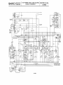
T.18 POWER PACK AND SOUND SECTION 12 (3)
CIRCUIT DIAGRAM
35/4020
SERVICE
MANUAL
r-------...,--..,.------------------... C.RI ANODE
r--l
'
l27~
1~128
I~
1'1
I~?T~N~J~ I
~ C.RJ HEATER
== C39
V6
pg:A
:=:B
~l30
C-
-+
VISION
POWER
SOCKET
EI:(20V)
f
1'---1
~l32
l35
pL33
Lvt-
"0
R26
~
Vl~fW"""'-~1---Io
0
r--
SS GANGED
WITH VR3
R.F AMP.
l37
3.
FUSE
R29
11
~
~MAINI
17
GANGED
WITH VRI
L
~
R27 VR4
C'j7
R26
V7
of
POWER
"F08
FC36
I~f~fER-ll
J;.il
"FC33
C34
B
lOCKET
FlAME..--,J AMP
"';II
foe:: :::::- -::::: :::::::::::::: co:::::::::: :::::::::::::::: ::::::::::::::::··::::i040
:;
lI7~~:··T(·~~·+·:··---11
MAINS AERIAL
:-9.1:
11
.I!C7
CII
I
__~_ _l_18+:~~~~~~'~.~.~.~
..
~-~--~--~.~--~.~.~.~._~.~_~_~_.~~,
r
:
R7 j, ......~-~
-_.
_._- ._._-- .....
o
RS
R4
C
lOCKET
l.~~? ___ .. ~
.
CS
--") {
'--'7,,",/.~ f~
I
DIAL
l::P\
~
~~"
i~rwi~
ll~
~~
3~ (~~J
C3'~ R~2 ~~lfC;-:-~1 ~.:: ~
..... A£
I
C4
C9'
TelO
__
\~:
I~ L-
l~ ~_Ll6_~I~ J
~_ ~
'7 ~-
}r; l~
l21
R6
Tel2
==.
CI4
t - - - + -.... EXTENSIOH
lS SOCKETS
"
R20
Rn
1I
if
CI6
t~~'
1'0
IAR9
r
PU
(15
C20
R23
,
C25
• TAGS ON SWITCHES S3 £, S4
SHOWN THUS' 0 .RE USED
RI
FOR A.NCHORING PURPOSES
ONLY C. ARE NOT CONTACTS.
RI4
!Cs"flt
.\
l7
'j
~1Il
~T=r.
_~
l6 lC4 (26
TO TElEVIIION
AERIAL
A
7[.i,
1
::
~I!
1
=l=C24
V4
~:~
~;r
.............""",~"<VV.,.........J
:,:::::::::::::::J
RI8
RI9
35/6008
BAI RD
SERVICE
MANUAL
TELEVISION AERIAL AND LOUD- SECTION 13 (I)
SPEAKER CONNECTIONS
35/4020
T 18 AND T 20 AERIAL FEEDER CABLE PLUG CONNECTIONS
BRAIDING TO CASE
C6
SMAllEI' PIN
CENTRE CONDUCTOR.
TO LARGER PIN
35/6003
T 18 AND T 20 LOUDSPEAKER CIRCUIT DIAGRAM
INSIDE OF
PLUG
35/6004
BAIRD
T.IS AND T.20 TIME BASE
COMPONENT VALUES
SERVICE
MANUAL
RESISTORS
CONDENSERS
K = X by 1000
W = Wattage
M = Megohm
T
Tubular
E= Electrolytic
RI.
R2.
R3.
IM.
200K.
15K.
RA.
15K.
R5.
50K.
R6.
lOOK.
R7.
2K.
RS. 100 to 500 ohms
R9.
0.5M.
R.IO.
lK.
Rll.
19K.
R12.
20K.
e.l.
e.2.
C.3.
tw.
tw.
tw.
tw.
tw.
tw.
2w.
lw.
tw.
tw.
lw.
2w.
CA.
e.5.
e.6.
e.7.
e.S.
e.9.
e.1O.
e.ll.
e.12.
C.13.
VARIABLE RESISTORS
V.RI.
V.R2.
V.R3.
V.R4.
=
=
=
=
2K.
2K.
50K.
20K.
VALVES
V.l.
V.2.
V.3.
VA.
V.5.
V.6.
A.C.2/H.L. Mazda
2.DA.A. Mullard
4I.M.P. Cossor
U.RI.e. Mullard
2.DA.A. Mullard
4I.M.P. Cossor or AC/P Mazda
0.1 mfd. T
.oI
T.
.001
T.
0.25
T.
50
E.
0.5
T.
0.5
T.
deleted"
.0025 mfd. 2000
S mfd. 120v.w.
S
l20v.w.
S
450v.w.
"
S
450v.w.
"
SECTION 14 (I)
35/4020
v.w.
E.
E.
E.
E.
COILS
L.l.
K
L.2.
L.3.
LA.
L.5.
L.6.
L.7.
Line Scan oscillator transformer
primary.
Line Scan oscillator transformer
secondary.
Line Deflector coil on C.RT.
"
"
"
Shift coil on Frame deflector Yoke.
"
Frame deflector oscillator transformer
primary.
L.S. Frame deflector oscillator transformer
secondary.
L.9. Shift Choke.
L.IO. Focus Coil.
CATHODE RAY TUBE
POWER LEAD
T.lS.
T.20.
Power Lead terminated with 6-way Carr Plug
and separate Earthing Plug
"Cathovisor" Type l2.M.W.2
" 9.M.W.2
BAIRD SERVICE
MANUAL
RESISTORS
K = XbylOoo
W = Wattage
75 ohms
R.l.
lw.
7.SK
R.2.
lw.
SK
R.3.
lw.
SK
R.4.
lw.
SK
R.S.
lw.
1250 ohms
R.6.
lw.
ISOK
R7.
two
20K
Iw.
R.8.
3SK
Iw.
R.9.
R.IO. 70K
two
SK
R.II.
lw.
SK
R12.
lw.
R13. 7.SK
lw.
SK
R.14.
two
R.lS. 1250 ohms
lw.
R16. IS0K
lw.
lw.
R.17. 20K
R.18. SOOK
lw.
R19. tOK
lw.
R20. SK
two
R2I. 200 ohms
lw.
R22. SK
lw.
R23. 70K
two
R24. 20K W.W., tapped at
ISK + 35 Ktw. paralleled
T.IS AND T.20 VISION
COMPONENT VALUES
SECTION 14 (2)
35/4020
CONDENSERS
COILS
C.l.
C.2.
C.3.
C.4.
C.S.
C.6.
C.7.
C.8.
C.9.
C.lO.
C.II.
C.I2.
C.I3.
C.14 .
C.lS .
C.16 .
C.17 .
C.18.
C.19 .
C.20 .
C.21.
C.22.
C.23 .
C.24.
C.2S .
C.26.
C.27 .
C.28 .
C.29.
C.30.
L.l.
30P.F.
looP.F.
.002 mfd.
.002 mfd.
.002 mfd.
.002 mfd.
.002 mfd.
.002 + .002 mfd.
.002mfd.
0.1 mfd.
.002 mfd.
4 mfd. E.
.002 mfd.
.002 mfd.
.002 mfd.
.002 mfd.
.002 mfd.
.002 mfd.
.002 mfd.
.002 mfd.
.002 mfd.
.002 mfd.
.002 mfd.
15 P.F.
.02 mfd.
.02 mfd.
.002 mfd.
.002 mfd.
200 mfd. E.
4 mfd. E.
L.2.
L.3.
L.4 .
L.S .
L.6.
L.7.
L.8.
L.9.
L.I0.
L.ll.
L.12.
L.13.
L.14.
L.lS.
L.16.
L.I7.
L.I8.
Sound RF. Rejector Coil
(Capacity tuned)
Vision RF. Grid Coil
(Capacity tuned)
Vision RF. Band Pass,
Anode Coil (Inductance
tuned)
RF. Choke. H.T. Supply
1st valve
RF. Choke. V.l. Screen
RF. Choke. Heater supply
V.l.
RF. Choke. Heater supply
V.I.
RF. Band Pass, V.2. coupling coil
RF. Choke. V.2. Screen
RF. Band Pass, V.2. Grid
coil (Inductance tuned)
RF. Band Pass Anode Coil
V.2. (Inductance tuned)
RF. Band Pass V.3. Coupling Coil
RF. Band Pass V.3. Diode
Coil (Inductance tuned)
RF. Choke V.4. Grid
RF. Choke Heater supply
V2. V.3
RF. Choke Heater supply
V2. V.3
R.F. Choke V4. Anode
R.F. Choke V4. Auxiliary
Cathode
VALVES
VI.
V2.
V3.
V4.
TSE4
TSE4
DI
TSE4
Mullard
Mullard
Mazda
Mullard
BAIRD SERVICE
MANUAL
T.IS AND T.20 VISION AND TIME
BASE CIRCUIT DIAGRAMS
SECTION 14 (3)
35/4020
VISION DIAGRAM
qp
6
L4
Ll7
1\3
R7
RI4
11.9
RI&
C9
R20
CI9
RI9
R23
C25
POWER PLUG
VIEW LOOKING
AT PINS.
3
RII
A
l6
'2
L7
35/6006
TIME BASE DIAGRAM
GIUUI
1\2
R3
R8
RS
C4
RID
R9
RI'2
QEQ
OFO
RI
R&
cr'b
POWER PLUO
VIEW LOOKING
AT PINS.
CHASSIS
35/6007
RIO
H
BAIRD
SERVICE
MANUAL
T.20 POWER PACK AND SOUND SECTION IS <I)
COMPONENT VALUES
35/4020
RESISTORS
M = Megohm.
K = X by 1000.
W = Wattage.
RI.
R2.
R3.
R.4.
R5.
R6.
R7.
R8.
R9.
RIO.
R11.
R12.
R13.
R14.
R15.
R16.
R17.
R1S.
R19.
R20.
R21.
R22.
R23.
V.Rl.
V.R2.
V.R3.
V.R4.
CONDENSERS
T = Tubular.
E = Electrolytic.
50 K.
l.w.
150ohmstw.
50.K.
two
2w.
20.K.
1 M.
two
5M.
two
lOOK.
two
100ohmstw.
lOOK.
two
1 M.
two
500 ohms two
50K.
two
20K.
two
SOOK.
two
lOOK.
two
300 ohms two
10K.
two
SOK.
1w.
2S0 ohms tw.
50 ohms 4w.
.07 ohms 20 s.w.g. Eureka.
50K.
two
2 M.
two
VARIABLE RESISTORS
500 K. Audio Volume Control
100 K.
Tone Control
5 K. Vision Contrast Control
1OK. e.R Tube Brightness control
V.l.
V.2.
V.3.
V.4.
V.5.
V.6.
AC/THl.
VP4.B.
TDD4.
PEN.A.4.
IW4/350.
H.V.'R2.
Mazda.
Mullard.
Mullard.
Mullard.
Mullard.
Mullard.
e.l.
C.2.
e.3.
C.4.
e.5.
e.6.
e.7.
C.S.
e.9.
C.lO.
e.11.
e.12.
e.13.
C.14.
C.15.
C.16.
e.17 .
C.1S.
e.19.
e.20.
e.21.
C.22.
C.23.
e.24.
C.25.
C.26 .
e.27.
e.2S.
e.29.
25 P.F.
.01 mfd. T.
.001 mfd. T.
50 P.F.
50 P.F.
50 P.F.
100 P.F.
0.1 mfd. T.
.01 mfd. T.
.01 mfd. T.
50 P.F.
50 P.F.
.0001 mfd. T
.01 mfd. T.
.001 mfd. T.
.02 mfd. T.
.01 mfd. T.
.01 mfd. T.
2 mfd. E.300 V.W.
50 mfd. E.12 V.W.
50 mfd. E.12 V.W.
.35 mfd. T.
16 mfd. E.4S0 V.W.
16 mfd. E.450 V.W.
16 mfd. E.450 V.W.
S mfd. E.120 V.W.
.02 mfd. T.SOOO V.W.
0.1 mfd. 400 v.w.T.
0.1 mfd. 400 v.w.T.
VARIABLE CONDENSERS
T.e.l. 30. P.F. RF. Grid Coil Trimmer
T.e.2. 30. P.F. Osc. Tuning Preset
T.e.3. 20. P.F. I.F. Trimmer
T.C.4. 20. P.F.
"
"
T.e.5. 25. P.F. Osc.
Tuning
Sound
T.e.6. 30. P.F. I.F. Trimmer
VALVES
Frequency Changer
I.F. Amplifier
Detector, A.V.e. Rectifier and Audio Amplifier
Pentode Output Valve
H.T. Rectifier
E.H.T. 5,OOOv. Rectifier
COILS
L.t.
L.2.
L.3.
L.4.
L.5.
L.6.
L.7.
L.8.
L.9.
L.1O.
Aerial Coupling Coil
RF. Grid Coil
1st I.F. Coil 2.5 m/cs.
RF. Osc. Trans£. Secondary
RF. Osc.
"
Primary
2nd I.F. Coil. 2.5 m/cs.
Audio Output Transformer Primary
Audio Output Transformer Secondary
Smoothing Choke. H.T. Supply
4.v. A.e. Rectifier Heater Winding
L.11.
L.12.
L.13.
L.14.
L.15.
L.16.
L.17.
L.1S.
330-0-330. V.A.e. Rectifier Secondary
Winding
20.v. A.e. Heater Winding
4.v. 20 amp. A.C. Heater Winding for
Sound Time Base and Vision
e.RT. Heater Winding
Mains Transformer Primary
E.H.T. A.e. Secondary 3,200v.
E.H.T. 4.v. Heater Winding
E.H.T. Mains Transformer Primary
..
08
l!
~~ J
AERIAL
4
rC6f
7
r r
E
CHAISI5./
1"'''~~~
R6
~Et
3&/600&
Ci9
I-
R23
@VISION
D2
!Cl TIME' BAs[ POWER
cID R.f. AMPlifiER 02
02
02
SOCKET
C.RJ. ANODE
C27
•
•SI
C26·-....4-I_ _.....7
CRr. HEATER
•
05
Wi J! r(
••.•
lOUD
_~ ::::~b~~frr~-~l
-4-J l;R14
r
VR'2
Jl
C29
1I 6 ~2 GANGEI) WITH VR3
S3 GANGW WITH VRI
RI2
3
r~
rf.~1!lI,1
~roll1JhTl
:~fLI---- --------,
Rn
~
IV
---
IV
0,,,"
~z
~IO
q
m
V)
o
z
oC
V)
:::cz
»0
3:
G)>
»7'
O~
-1""'0
()m
:::c~
c:::C
()O
""'0
:-I
rm
»()
c<
V)
»m
z:::C
3:
o
:::c
»
OJ
This service manual © 2014.