1
Software
Development Kit
2711P
User Manual
Important User Information
Solid state equipment has operational characteristics differing from those of
electromechanical equipment. Safety Guidelines for the Application,
Installation and Maintenance of Solid State Controls (publication SGI-1.1
available from your local Rockwell Automation sales office or online at
http://literature.rockwellautomation.com) describes some important
differences between solid state equipment and hard-wired electromechanical
devices. Because of this difference, and also because of the wide variety of
uses for solid state equipment, all persons responsible for applying this
equipment must satisfy themselves that each intended application of this
equipment is acceptable.
In no event will Rockwell Automation, Inc. be responsible or liable for
indirect or consequential damages resulting from the use or application of
this equipment.
The examples and diagrams in this manual are included solely for illustrative
purposes. Because of the many variables and requirements associated with
any particular installation, Rockwell Automation, Inc. cannot assume
responsibility or liability for actual use based on the examples and diagrams.
No patent liability is assumed by Rockwell Automation, Inc. with respect to
use of information, circuits, equipment, or software described in this manual.
Reproduction of the contents of this manual, in whole or in part, without
written permission of Rockwell Automation, Inc., is prohibited.
Throughout this manual, when necessary, we use notes to make you aware
of safety considerations.
WARNING
IMPORTANT
ATTENTION
Identifies information about practices or circumstances that can cause
an explosion in a hazardous environment, which may lead to personal
injury or death, property damage, or economic loss.
Identifies information that is critical for successful application and
understanding of the product.
Identifies information about practices or circumstances that can lead
to personal injury or death, property damage, or economic loss.
Attentions help you identify a hazard, avoid a hazard, and recognize
the consequence
SHOCK HAZARD
Labels may be on or inside the equipment, for example, a drive or
motor, to alert people that dangerous voltage may be present.
BURN HAZARD
Labels may be on or inside the equipment, for example, a drive or
motor, to alert people that surfaces may reach dangerous
temperatures.
Allen-Bradley, PanelView, Rockwell Automation, and TechConnect are trademarks of Rockwell Automation, Inc.
Trademarks not belonging to Rockwell Automation are property of their respective companies.
Table of Contents
Preface
Using this Manual . . . .
Intended Audience . . .
Purpose of this Manual
Manual Conventions . .
Additional Resources. .
.
.
.
.
.
.
.
.
.
.
.
.
.
.
.
.
.
.
.
.
.
.
.
.
.
.
.
.
.
.
.
.
.
.
.
.
.
.
.
.
.
.
.
.
.
.
.
.
.
.
.
.
.
.
.
.
.
.
.
.
.
.
.
.
.
.
.
.
.
.
.
.
.
.
.
.
.
.
.
.
.
.
.
.
.
.
.
.
.
.
.
.
.
.
.
.
.
.
.
.
.
.
.
.
.
.
.
.
.
.
.
.
.
.
.
.
.
.
.
.
.
.
.
.
.
.
.
.
.
.
.
.
.
.
.
.
.
.
.
.
.
.
.
.
.
7
7
7
7
8
Hardware Architecture . . . . . .
CPU . . . . . . . . . . . . . . . . .
Memory Devices . . . . . . . .
Input/Output . . . . . . . . . . .
ATMEL Microcontroller. . . .
Software Architecture . . . . . . .
Windows CE OS Overview.
Boot and Startup Sequence
The Windows CE Registry .
File Systems. . . . . . . . . . . .
Input Devices . . . . . . . . . .
PCI Bus . . . . . . . . . . . . . . .
PCMCIA. . . . . . . . . . . . . . .
Run Time Environment . . .
.
.
.
.
.
.
.
.
.
.
.
.
.
.
.
.
.
.
.
.
.
.
.
.
.
.
.
.
.
.
.
.
.
.
.
.
.
.
.
.
.
.
.
.
.
.
.
.
.
.
.
.
.
.
.
.
.
.
.
.
.
.
.
.
.
.
.
.
.
.
.
.
.
.
.
.
.
.
.
.
.
.
.
.
.
.
.
.
.
.
.
.
.
.
.
.
.
.
.
.
.
.
.
.
.
.
.
.
.
.
.
.
.
.
.
.
.
.
.
.
.
.
.
.
.
.
.
.
.
.
.
.
.
.
.
.
.
.
.
.
.
.
.
.
.
.
.
.
.
.
.
.
.
.
.
.
.
.
.
.
.
.
.
.
.
.
.
.
.
.
.
.
.
.
.
.
.
.
.
.
.
.
.
.
.
.
.
.
.
.
.
.
.
.
.
.
.
.
.
.
.
.
.
.
.
.
.
.
.
.
.
.
.
.
.
.
.
.
.
.
.
.
.
.
.
.
.
.
.
.
.
.
.
.
.
.
.
.
.
.
.
.
.
.
.
.
.
.
.
.
.
.
.
.
.
.
.
.
.
.
.
.
.
.
.
.
.
.
.
.
.
.
.
.
.
.
.
.
.
.
..
..
..
..
..
..
..
..
..
..
..
..
..
..
. 9
10
10
12
14
15
15
16
17
19
20
25
25
25
Overview . . . . . . . . . . . . . . . . . . . . . . .
Application Distribution and Installation.
Installing the Application . . . . . . . . .
Remote Installations . . . . . . . . . . . . .
Application Upgrades. . . . . . . . . . . .
Persistency Considerations. . . . . . . . . . .
Set up the Development System . . . . . .
.
.
.
.
.
.
.
.
.
.
.
.
.
.
.
.
.
.
.
.
.
.
.
.
.
.
.
.
.
.
.
.
.
.
.
.
.
.
.
.
.
.
.
.
.
.
.
.
.
.
.
.
.
.
.
.
.
.
.
.
.
.
.
.
.
.
.
.
.
.
.
.
.
.
.
.
.
.
.
.
.
.
.
.
.
.
.
.
.
.
.
.
.
.
.
.
.
.
29
29
30
30
30
31
31
Chapter 1
Introduction to the PanelView
Plus CE Terminal
Chapter 2
Developing CE Applications
.
.
.
.
.
.
.
Chapter 3
PanelView Plus CE SDK
Overview . . . . . . . . . . . . . . . . . . . . . . . . . . . . . . . . . . . . . . 33
Version Management. . . . . . . . . . . . . . . . . . . . . . . . . . . . . . 33
Visual Basic .NET . . . . . . . . . . . . . . . . . . . . . . . . . . . . . . . . 34
Chapter 4
PanelView Plus CE-Specific
Extensions to the WinCE API
3
Overview . . . . . . . . . . . .
Watchdog Control . . . . . .
Hardware Watchdog . . . .
Watchdog_Tag. . . . . .
Software Watchdog . . . . .
Watchdog_SW_TagEx
Watchdog_SW_Tag . .
.
.
.
.
.
.
.
.
.
.
.
.
.
.
.
.
.
.
.
.
.
.
.
.
.
.
.
.
.
.
.
.
.
.
.
.
.
.
.
.
.
.
.
.
.
.
.
.
.
.
.
.
.
.
.
.
.
.
.
.
.
.
.
.
.
.
.
.
.
.
.
.
.
.
.
.
.
.
.
.
.
.
.
.
.
.
.
.
.
.
.
.
.
.
.
.
.
.
.
.
.
.
.
.
.
.
.
.
.
.
.
.
.
.
.
.
.
.
.
.
.
.
.
.
.
.
.
.
.
.
.
.
.
.
.
.
.
.
.
.
.
.
.
.
.
.
.
.
.
.
.
.
.
.
.
.
.
.
.
.
.
.
.
.
.
.
.
.
..
..
..
..
..
..
..
35
35
36
36
37
37
41
Publication 2711P-UM005A-EN-P - March 2007
4
Table of Contents
System Parameters . . . . . . . . . . . . . . . . . . . . . . . . . .
System Parameters and Data Types. . . . . . . . . . . .
Read or Write System Parameters . . . . . . . . . . . . .
rm_GetParameter . . . . . . . . . . . . . . . . . . . . . . . . .
rm_SetParameter . . . . . . . . . . . . . . . . . . . . . . . . .
System Timers. . . . . . . . . . . . . . . . . . . . . . . . . . . . . .
Configure Timer Functions . . . . . . . . . . . . . . . . . .
UserTimerGetNumberOfTimers. . . . . . . . . . . . . . .
UserTimerClaim . . . . . . . . . . . . . . . . . . . . . . . . . .
UserTimerRequestFrequency . . . . . . . . . . . . . . . .
UserTimerGetWaitEvent . . . . . . . . . . . . . . . . . . . .
Run Timer Functions . . . . . . . . . . . . . . . . . . . . . .
UserTimerSet . . . . . . . . . . . . . . . . . . . . . . . . . . . .
UserTimerSetEx . . . . . . . . . . . . . . . . . . . . . . . . . .
UserTimerGetValue . . . . . . . . . . . . . . . . . . . . . . .
UserTimerStop . . . . . . . . . . . . . . . . . . . . . . . . . . .
Hardware Monitor. . . . . . . . . . . . . . . . . . . . . . . . . . .
Hardware Monitor Parameters . . . . . . . . . . . . . . .
Hardware Monitor Functions . . . . . . . . . . . . . . . .
hm_RegisterMonitorWarningEvent . . . . . . . . . . . .
hm_UnregisterMonitorWarningEvent. . . . . . . . . . .
hm_GetMonitorWarnings . . . . . . . . . . . . . . . . . . .
hm_GetMonitorLevel . . . . . . . . . . . . . . . . . . . . . .
hm_SetMonitorWarningLevels. . . . . . . . . . . . . . . .
hm_GetMonitorWarningLevels . . . . . . . . . . . . . . .
Shutdown and Re-Boot Functions. . . . . . . . . . . . .
hm_RebootBoard . . . . . . . . . . . . . . . . . . . . . . . . .
hm_GetBootReason . . . . . . . . . . . . . . . . . . . . . . .
Keypad. . . . . . . . . . . . . . . . . . . . . . . . . . . . . . . . . . .
Keypad Overview . . . . . . . . . . . . . . . . . . . . . . . .
Keypad Driver/Handler Overview . . . . . . . . . . . .
Keypad Driver Streams Interface. . . . . . . . . . . . . .
Registry Keys for Keypad Driver/Handler Interface
System Event Log . . . . . . . . . . . . . . . . . . . . . . . . . . .
Event Data Structure . . . . . . . . . . . . . . . . . . . . . .
Log New Event . . . . . . . . . . . . . . . . . . . . . . . . . .
Clear Event Log . . . . . . . . . . . . . . . . . . . . . . . . . .
Get Last Event . . . . . . . . . . . . . . . . . . . . . . . . . . .
Get First Event . . . . . . . . . . . . . . . . . . . . . . . . . . .
Get Next Event . . . . . . . . . . . . . . . . . . . . . . . . . .
Recommended PanelView Plus CE Mechanisms . . . . .
Disable Keypad Handler . . . . . . . . . . . . . . . . . . .
Lock Pages . . . . . . . . . . . . . . . . . . . . . . . . . . . . .
UnLock Pages . . . . . . . . . . . . . . . . . . . . . . . . . . .
SetSystemMemoryDivision . . . . . . . . . . . . . . . . . .
Publication 2711P-UM005A-EN-P - March 2007
.
.
.
.
.
.
.
.
.
.
.
.
.
.
.
.
.
.
.
.
.
.
.
.
.
.
.
.
.
.
.
.
.
.
.
.
.
.
.
.
.
.
.
.
.
.
.
.
.
.
.
.
.
.
.
.
.
.
.
.
.
.
.
.
.
.
.
.
.
.
.
.
.
.
.
.
.
.
.
.
.
.
.
.
.
.
.
.
.
.
.
.
.
.
.
.
.
.
.
.
.
.
.
.
.
.
.
.
.
.
.
.
.
.
.
.
.
.
.
.
.
.
.
.
.
.
.
.
.
.
.
.
.
.
.
..
..
..
..
..
..
..
..
..
..
..
..
..
..
..
..
..
..
..
..
..
..
..
..
..
..
..
..
..
..
..
..
..
..
..
..
..
..
..
..
..
..
..
..
..
42
42
45
45
46
47
48
48
49
50
52
53
53
54
56
57
58
58
59
59
60
61
62
63
65
66
66
67
69
69
70
70
72
73
73
74
75
76
77
78
80
80
81
82
82
Table of Contents
5
Chapter 5
Device Drivers
Overview . . . . . . . . . . . . . . . . . . . . . . . . . . . . . . . . . . . . . . 83
Developing a Device Driver . . . . . . . . . . . . . . . . . . . . . . . . 83
Sample Code . . . . . . . . . . . . . . . . . . . . . . . . . . . . . . . . . . . 85
Appendix A
Messages
Serial Debug Messages . . . .
Exception Debug Messages .
C++ Name Mangling . . . . . .
Path . . . . . . . . . . . . . . . . . .
Error Codes . . . . . . . . . . . .
.
.
.
.
.
.
.
.
.
.
.
.
.
.
.
.
.
.
.
.
.
.
.
.
.
.
.
.
.
.
.
.
.
.
.
.
.
.
.
.
.
.
.
.
.
.
.
.
.
.
.
.
.
.
.
.
.
.
.
.
.
.
.
.
.
.
.
.
.
.
.
.
.
.
.
.
.
.
.
.
.
.
.
.
.
.
.
.
.
.
.
.
.
.
.
.
.
.
.
.
.
.
.
.
.
.
.
.
.
.
.
.
.
.
.
.
.
.
.
.
97
98
98
99
99
Index
Publication 2711P-UM005A-EN-P - March 2007
6
Table of Contents
Publication 2711P-UM005A-EN-P - March 2007
Preface
Using this Manual
Read this preface to familiarize yourself with the rest of the manual.
The preface covers these topics:
•
•
•
•
Intended audience
Purpose of the manual
Manual conventions
Additional resources
Intended Audience
Use this manual if you are responsible for developing application
software to run on the PanelView Plus CE device.
Purpose of this Manual
This manual is a user guide for the Software Development Kit for the
PanelView Plus CE device. It gives an overview of the system and
provides detailed information about the contents of the software
development kit.
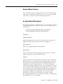
Manual Conventions
The following conventions are used throughout this manual:
• Bulleted lists such as this one provide information, not
procedural steps.
• Numbered lists provide sequential steps or hierarchical
information.
7
Publication 2711P-UM005A-EN-P - March 2007
8
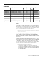
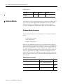
Additional Resources
For additional information, refer to these publications, that you can
download from:
http://literature.rockwellautomation.com.
Resource
Description
PanelView Plus User Manual, publication
2711P-UM001
Provides an overview of the PanelView
Plus and PanelView Plus CE terminals.
Also provides information and
procedures on how to install, operate,
replace components, connect other
devices, and troubleshoot the terminals.
Wiring and Grounding Guidelines for PanelView Provides grounding and wiring
Plus Terminals Technical Data, publication
guidelines for PanelView Plus terminals.
2711P-TD001
Publication 2711P-UM005A-EN-P - March 2007
Chapter
1
Introduction to the PanelView Plus CE
Terminal
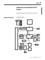
This chapter provides an overview of the PanelView Plus CE
terminals, including the hardware and software architecture.
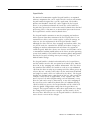
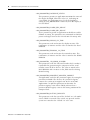
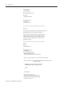
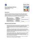
Hardware Architecture
Functional Block Diagram
Power Supplies
5Volts in
CPU core
1.1V
CPU
Celeron
mlCP 650 MHz ULV
CPU I/O
1.25V
FSB 100 MHz
1.8V
3.3V
LCD
Interface
CPLD
GMCH
FW82810E
256 MB
SODIM
Analog VGA interface
Display Interface Connectors
ICH2 HUB Bus
I2C Bus
USB bus
2xUSB
connector
Primary IDE
Compact flash
USB Port 4
AC97 interface
AC97 Audio
ICH2
FW82801BA
LAN interface
82562ET
AGP
connector
PCI bus 33 MHz
RTC
Third USB Port
LPC Bus
Dual
PC card
Controller
PCI1225
Removable
Compact
Flash
Firmware Hub
SST49LF008A
IrDA
Super IO
SMSC
LPC47N267
COM1
Key
Scan
Backlight
PWM and
GP I/O's
Atmel
MEGA128
or
MEGA64
X Bus
Touch
interface
UART
LED's
9
Publication 2711P-UM005A-EN-P - March 2007
10
Introduction to the PanelView Plus CE Terminal
CPU
The system processor is an Intel mlCP 650MHz, ultra low-voltage
Celeron processor (P/N RJ80530VY650256) with 100 MHz front side
bus. There is 32k (16k instruction and 16k write-back data) of L1
cache memory and 256k of L2 cache memory integrated on the
Celeron processor. The thermal design allows for a maximum ambient
temperature of 55C without the use of a fan.
The primary support chipset is the 82810E Graphics And Memory
Controller Hub (GMCH) commonly referred to as the Eight-Ten-E. The
GMCH provides the interfaces between the CPU, system memory,
graphics displays, and downstream system I/O logic, including the
PCI bus. It integrates a system bus controller, 2D/3D graphics
accelerator, SDRAM controller, and an interface to a 82801BA I/O
Controller Hub (ICH2).
Memory Devices
There are three types of memory devices: Compact Flash ROM,
BootROM, and DRAM.
Compact Flash ROM
The logic board has two Type 2 Compact Flash connectors, one
internal and one external.
The internal connector is on the primary IDE interface and supports
the power requirements defined by the CompactFlash+ specification.
The internal CF “slot” is not hot-pluggable and supports only 3.3V CF
devices. The internal CF slot is populated at the factory and is
organized into 3 partitions as follows:
1. The compressed image of the Win CE operating system.
2. The compressed image of the persistent Win CE registry.
3. The FAT file system, presented as the volume named “\Storage
Card”
Only the fat file system is directly accessible to an application program
via standard Win32 file operations; e.g ReadFile().
Publication 2711P-UM005A-EN-P - March 2007
Introduction to the PanelView Plus CE Terminal
11
The external CF connector is controlled by a PCMCIA controller on
the PCI bus and is hot-pluggable and supports both 5V and 3.3V CF
devices. The external CF device is presented as the FAT volume
named “\Storage Card2”. The external connector is accessible via a
slot in the chassis and provides a convenient way to transport files
to/from the PanelView Plus CE device. Additionally, programs can be
run from the external CF device and it can extend the integral,
non-volatile storage areas of the system.
Boot ROM
The boot code resides in a 1Mbyte 82802AB Firmware Hub (FWH).
The code within the FWH is split into two sections. The first section is
referred to as the Basic Boot Code (BBC) and is 196Kbytes in size and
is not field programmable. The function of this code is to provide an
immutable code area for the initial start-up of the system. The second
section is referred to as the Extended Boot Code (EBC) and is
re-programmable. The EBC performs extended power-on self-testing
(POST), and initializes the system and readies it for the Win CE OS.
Much of the support for the manufacturing environment resides in the
EBC in the form of a Test Monitor.
Start-up is a sequential, and largely single-threaded operation. BBC
loads an existing or new EBC, and the EBC initializes the system and
loads an existing or new Win CE OS.
DRAM
The PanelView Plus CE device uses industry standard 3.3V, PC100/133
compliant, non-ECC, no-parity, dynamic RAM, packaged in a 144-pin
SO-DIMM. The DRAM comes in 64 MB, 128 MB, and 256 MB modules
and is field upgradable. The RAM provides a fast-access, volatile
storage space for data and program code during run-time.
The Win CE Operating System uses part of the RAM for a RAMDISK
and the other part for normal system memory. The RAMDISK portion
is commonly known as the Object Store and provides specialized
storage for the Windows CE Registry and Windows CE file system and
system databases. The Windows CE Control Panel System Properties
tool has a slider control that allows a user to determine how the RAM
is allocated between Storage and Program memory. The slider control
is factory set for a 50/50 split. Application programs can control RAM
allocation with the Windows CE system call SetSystemMemoryDivision
(see Microsoft’s documentation of the CE API for details).
Publication 2711P-UM005A-EN-P - March 2007
12
Introduction to the PanelView Plus CE Terminal
Input/Output
An INTEL 82801BA I/O CONTROLLER HUB (ICH2) provides an
interface between the CPU/Memory/Graphics logic, the PCI bus and
the I/O devices.
The main features integrated into the ICH2 are:
• 10/100BaseT Ethernet
• Dual UHCI USB host controllers support 2 downstream ports
each
• Two IDE Interfaces.
• PCI Bridge
• LPC Interface to the LPC47N267 Super I/O Controller (SIO) and
the Firmware Hub
• RTC embedded
• AC97 Interface
LAN Interface
10/100Mb Ethernet functionality is integrated within the ICH2. The
PHY is an Intel 82562ET that is wired to an RJ-45 connector. A green
LED indicates a good connection. A yellow LED indicates that the
transmitter is active.
USB Ports
The ICH2 has 2 USB host controllers, which support both full 12MHz,
and sub-channel 1.5MHz speeds. The 2 external USB ports come from
the primary host controller. The secondary host controller is wired to
the display interface connector and the PCI connector for future
usage. They are unsupported in the current product. All USB ports
support 500mA per port on the Vcc.
The USB port is capable of supporting a variety of peripheral devices,
for example keyboards, printers, bar code readers, and storage
devices. The platform supports:
• USB HID Class - Keyboard, mouse, bar code reader
• USB Printer Class - PCL compatible printers
• USB Storage Class - Flash drives
IDE
The primary IDE channel of the ICH2 supports the internal Compact
Flash card. The secondary channel is unused.
Publication 2711P-UM005A-EN-P - March 2007
Introduction to the PanelView Plus CE Terminal
13
PCI
The PanelView Plus CE device uses a PCI bus for expanding it
communications options and may support other card types in the
future. The PCI interface supports a communication option that is
accessible via a slot on the back chassis of the Logic Module. A
half-slot PCI card is housed in a separate communication module that
attaches to the backside of the Logic Module. The connector to the
communications module is actually an AGP connector to fit the space
available, but the pinouts and signaling are PCI. The ICH2 provides an
external PCI interface that supports 5V, 33MHz, 32 bit, version 2.2,
standard-PC, PCI cards. The external PCI interface is bus 1.
The PCMCIA controller for the external CF and NVRAM is also on the
PCI bus.
Real-time Clock
The ICH2 provides an RTC with standard PC clock/calendar
functionality. The battery is a socketed CR2032 or equivalent.
Sufficient hold-up capacitance exists on the battery circuit to allow 2
minutes to remove the old battery and replace it with the new one.
This will prevent configuration data from being lost during battery
replacement. The design provides 46ppm accuracy without trimming
in manufacturing
Integral with the RTC is a small section of battery-backed, non-volatile
CMOS that supports several board level parameters including the
clock/calendar.
Serial Port
Signals from the SIO are optically isolated and routed to an external
standard 9 pin male D-type connector to provide a 16550A compatible
serial port. The port is configured as DCE and is known to CE as
COM1. The pin-outs are identical to PanelView standard products, so
existing cables should be compatible.
In addition to supporting serial communications, the port is a useful
and convenient debugging tool wherein an application developer or
tester can utilize the port to display debug text messages to determine
the current state of the operating system, or to identify problems such
as device failures or application exceptions.
Publication 2711P-UM005A-EN-P - March 2007
14
Introduction to the PanelView Plus CE Terminal
ATMEL Microcontroller
An Atmel 8-bit microcontroller is a coprocessor to provide an 8x8
keypad scanner, 4, 5, and 8-wire touchscreen interface, high-speed
timer, watchdog and to monitor the Celeron die temperature and shut
down the Celeron if the die temperature reaches its maximum
temperature rating. Additionally, the ATMEL plays a role in resetting
the system and controlling the display module backlight.
Watch Dog
The watchdog timer will trigger a system reset in the event the system
or an application loses control. The watchdog hardware is always
enabled and is tagged by the watchdog system service periodically
every 500 ms. One or more applications can register with the
watchdog service wherein the application must periodically tag
(restart) it to prevent it from timing out. If the watchdog times out, a
system reset (warm-boot) is initiated. Once the system has been
restarted, an application can inquire about the event that caused the
restart and learn that the watchdog timed out.
System Timer
A single 50-μs, high-resolution programmable hardware timer is
available to an application program.
Hardware Monitor
A software accessible hardware monitor provides real-time
temperature, voltage and battery monitoring. Thresholds for warnings
can be established programmatically by application programs.
Applications also have access to the system LED indicators.
Keypad
Certain configurations of the PanelView Plus CE device provide
function keys, a numeric keypad and cursor control keys integrated
into the front bezel. The number of function keys can vary. Some
function keys are relegendable. The keypad handler provides
extended software support. The keypad handler intercepts and
operates on codes produced by the keypad driver before passing
them to the application with current focus. The keypad handler can
optionally re-map keys (assign different virtual key codes) and effect
specialized processing such as the generation of key macros (strings
of virtual key codes) or the launching of a program from a single key
press.
Publication 2711P-UM005A-EN-P - March 2007
Introduction to the PanelView Plus CE Terminal
15
Touch Screen
An integral, resistive analog touch screen with a serial controller
provides mouse-like operator input. The touch screen is a factory
installed option.
Display Controller
The Intel 82810E integrates a powerful 64-bit graphics accelerator
engine for Bit Block Transfer (BitBLT), hardware cursor, and other
graphic intensive functions common to windowing environments.
Superior performance is achieved through a direct 32-bit interface to
the PCI-Local bus.
VGA (640 x 480), SVGA (800 x 600) and XGA (1024 x 768) flat panel
screen resolutions at 8 bit indexed, 16 bits or 24 bits per pixel at 60hz
scan rates are supported.
Software Architecture
This section provides information on the PanelView Plus CE software.
Windows CE OS Overview
Windows CE.NET 4.1 with the latest service packs is the PanelView
Plus CE operating system.
The system software includes the following major components:
• Boot Loaders. The boot loaders consist of the Basic Boot Code
(BBC) and Extended Boot Code (EBC) and reside in the
firmware hub.
• Windows CE Kernel OS, CE Modules and device drivers with
custom adaptations and enhancements for the PanelView Plus
CE hardware and functional requirements. These components
reside in a binary partition on the internal CF card as a
compressed binary image. The Windows CE Kernel OS provides
a Default Registry. The CE modules include the Windows
Explorer desktop and shell and the Control Panel for configuring
the device.
• Persistent Windows CE Registry, containing information relative
to specific application configurations. This component resides in
a separate binary partition on the internal CF card. If the
Persistent Registry does not exist, then the Default Registry is
used.
Publication 2711P-UM005A-EN-P - March 2007
16
Introduction to the PanelView Plus CE Terminal
• PanelView Plus CE components are a collection of applications
and associated system elements such as Internet Explorer and
Terminal Server Client that reside in the FAT partition of the
internal CF card. The PanelView Plus CE components are
non-essential and can be removed if unwanted or to free up
additional space on \Storage Card. The PanelView Plus CE
components and the installation program
(InstallFromStorageCard.exe) are distributed on the Accessories
CD, P/N 77159-951-55.
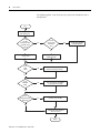
Boot and Startup Sequence
The Basic Boot Code (BBC) in the read-only section of the firmware
hub gets control when the system comes out of reset. The BBC is
simply a boot loader for the Extended Boot Code (EBC). As such, BBC
tests and sets up RAM, then initializes the serial port and optionally
the Ethernet if BBC Ethernet-boot (eboot) is enabled, and then looks
for a download of a new EBC on either the serial port or Ethernet.
Either the BBC receives and loads a new EBC into RAM, or copies an
existing EBC from the read/write section of the firmware hub into
RAM. Once a new and validated EBC is in RAM, it is copied into the
firmware hub where it replaces the existing EBC and is ready for the
next startup. Control is passed to the EBC in RAM.
The Extended Boot Code (EBC) continues hardware initialization, and
reads information from the Display Module about the type of display,
touchscreen and keypad. Video and the backlight are initialized and
the first startup text messages appear on the display. POST tests and
optionally Extended Diagnostics are performed. POST testing deals
with essential features such as RAM, stuck touch/key and dead
battery. A POST failure is reported by an error code on the display.
If EBC Ethernet-boot (eboot) is enabled, then EBC requests download
of a new OS via the Ethernet. If a new OS arrives, it is copied to RAM;
otherwise, EBC looks at the external CompactFlash card for a file
named SYSTEM.BIN and copies it to RAM if one exists. If a new and
valid OS resides in RAM, it is copied to a special partition on the
internal CompactFlash card where it replaces the existing OS and is
ready for the next startup. If not a new OS, then the existing OS is
copied from the internal CompactFlash card into RAM. Ultimately
control is passed to the Win CE OS in RAM.
The Win CE OS establishes the page tables and the virtual memory
system, enables interrupts, initializes the system clock and timers, and
completes the initialization of RAM. The Kernel and File System are
started. If the Persistent Win CE Registry exists in a special partition on
the internal CompactFlash it is copied into RAM; otherwise, the
Publication 2711P-UM005A-EN-P - March 2007
Introduction to the PanelView Plus CE Terminal
17
Default Registry that was extracted from the OS is used. Device drivers
are loaded, files are copied from \Storage Card\Windows\* to
\Windows\*. Once the file system is running, the OS looks for newer
versions of the EBC and ATMEL firmware that are distributed in the
file system, and if they exist, the EBC and/or ATMEL firmware is
automatically updated. The screen saver is started, the Explorer
desktop shell is started, and shortcuts in \Windows\RunOnce and
\Windows\Startup are executed to launch user applications.
The Windows CE Registry
The Windows CE Registry contains application and system
configuration data. The Default Registry resides within the operating
system image and is the native state of the Registry before any
applications are loaded. The Persistent Registry resides within a
special partition on the internal CompactFlash card and is the
aggregate of all application and user changes. The Control Panel
provides the user interfaces for managing the system settings that are
configurable by the user. Applications access the Registry
programmatically via the Win32 API.
At start-up, the Persistent Registry is loaded into and resides in RAM in
a special area sometimes referred to as the Object Store. If a valid
Persistent Registry does not exist, then the Default Registry is loaded.
Since the run-time Registry is in RAM and is volatile, any changes to
the Registry must be committed (flushed) to the Persistent Registry
TIP
The Default Registry is not the same as the out-of-box
condition, because application programs are actually loaded
during final assembly of the product. The Default Registry is
associated with the OS that originated it and shares the
identifying OS version level at the key [HKLM]\Ident\
RegistryVersion.
Publication 2711P-UM005A-EN-P - March 2007
18
Introduction to the PanelView Plus CE Terminal
Restoring the Default Registry
There are times when it is necessary to remove the Persistent Registry
and restore the Default Registry. There are 2 methods for achieving
the Default Registry:
1. Startup in the Safe Mode by pressing the Default and Reset
buttons on the right side of the chassis.
See the User Manual for details. The Safe Mode ignores the
Persistent Registry and uses the Default Registry. Note that the
Persistent Registry is not altered and returns on the next startup;
unless, the Default Registry is flushed. If flushed, the Default
Registry replaces the Persistent Registry. Normally, flushing the
Registry while in Safe Mode is undesirable because the Persistent
Registry is lost.
2. Remove the Persistent Registry and force a retreat to the Default
Registry.
The system parameter
RM_PARAMETER_PERSISTENT_REGISTRY_PRESENT allows an
application to delete the Persistent Registry. Note that until
rebooted, the Registry in RAM remains unchanged, so flushing
the Registry will effectively cancel the delete action. Normally, a
reboot immediately follows the call to delete the Registry. The
program RestoreRegistry.exe that is distributed on the Accessory
CD utilizes this system parameter.
When manipulating the Registry, applications and users should
exercise the same degree of caution that would be required of a
Windows NT/2000/XP system. Errant changes to the Registry can have
disastrous consequences, such as when device drivers are involved.
The Safe Mode provides a means to recover.
Registry Flushing
A specialized service runs continuously in the background and
monitors the Registry for changes every 2.5 seconds. Registry changes
may occur programmatically or by a User via Control Panel. When a
change is detected, the Registry is automatically flushed. This
mechanism is sometimes referred to as lazy flush since no other action
is required. Alternatively, the Registry can be persisted explicitly and
immediately by calling DeviceIoControl() with
CTL_SYSMON_FLUSH_REGISTRY. This is recommended whenever a
shutdown might occur before the lazy flush can confidently store
away the Registry changes.
Publication 2711P-UM005A-EN-P - March 2007
Introduction to the PanelView Plus CE Terminal
19
When the device is started in Safe Mode, the background service that
monitors the Registry for changes is suspended.
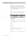
File Systems
The Windows CE operating system supports a DOS/Windows
compatible FAT file system that is implemented in a FAT partition on
the internal CompactFlash card, on the external CompactFlash card,
and a RAM file system that is implemented in system DRAM. Unlike
the CompactFlash, the RAM-based files are not persistent and are
reconstructed at every start-up. The RAM-based file system provides
the system root at the folder named My Computer. The file system can
be viewed and manipulated by the Windows Explorer utility and
DOS-like commands within the CMD shell. The CompactFlash files
appear at the root as the folders named \Storage Card and
\Storage Card2.
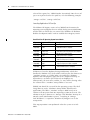
RAM File System
The RAM file system includes most of the known, standard Windows
folders, such as \Program Files, and most importantly, the \Windows
directory, where much of the system code and behavior resides at
runtime. The RAM-based file system is organized as follows:
RAM File System
Directory
Description
\Temp
Not used
\My Documents
Not used
\Program Files
Contains links (shortcuts) to certain system
Executables
\Windows
The Windows CE operating system – for example, system
executables (*.exe), dynamic link libraries (*.dll), fonts (*.ttf)
\Windows\Programs
Links (shortcuts) to specific executables. The links appear at
Start Menu > Programs
\Windows\Help
Links (shortcuts) to the Help System
\Windows\Desktop
Links (shortcuts) to specific executables. The links define the
contents of the Windows Desktop
\Windows\Favorites
Not used
\Windows\Fonts
Fonts in addition to the default font.
Publication 2711P-UM005A-EN-P - March 2007
20
Introduction to the PanelView Plus CE Terminal
RAM File System
Directory
Description
\Windows\Recent
Not used
\Windows\Startup
Links (shortcuts) to specific executables that are automatically
launched at startup.
\Windows\RunOnce
A folder that contains links (shortcuts) to specific executables
that are automatically launched at startup, and are then
deleted. Consequently, these links and this folder are
executed only one-time (run once).
The startup process copies all folders and their contents from
\Storage Card\Windows\* to \Windows\*. The net effect is to
re-construct the desktop, start menus, and control panel with OEM or
user content. Shortcuts that are copied to \Windows\Sartup or
\Windows\RunOnce will be launched by the initial instance of the
shell program. Additionally, the folder
\Storage Card\Windows\RunOnce is deleted so that the RunOnce
startup actions, in fact, only occur one time.
Input Devices
The PanelView Plus CE has a number of input devices.
Touch Screen
The PanelView Plus CE display can be equipped with a
high-resolution resistive touch screen. The Windows CE operating
system incorporates a driver for the touch screen. A user interface is
provided to enable touch screen configuration and calibration. Touch
screen calibration values are stored in the registry.
Keyboard/Keypad
The PanelView Plus CE device is designed to take key press input
from multiple sources. Support is present in the operating system for a
USB keyboard, and/or an optional keypad on the Display Module.
The device drivers permit either device to function alone or in
combination.
Publication 2711P-UM005A-EN-P - March 2007
Introduction to the PanelView Plus CE Terminal
21
Drivers for the Keyboard/Keypad/Touchscreen
Driver
Description
touch.dll
kbdmouse.dll
Loaded by GWES.EXE at startup. Responsible for low level
Keyboard/keypad related items and scan code to virtual key
mappings for the keyboard. Responsible for default virtual key to
virtual key mappings based on modifier keys and for virtual key
mappings, for both key input devices.
USBHID.dll
mouhid.dll
kbdhid.dll
USB Human Interface Device drivers, loaded by DEVICE.EXE upon
insertion/existence of a USB Human Interface Device. Handles USB
keyboard and mouse. Responsible for low-level USB related items
and scan code to virtual key mappings for USB keyboard. Submits
virtual key codes to Keybddrv.dll.
keypad.dll
PanelView Plus CE specific keypad driver that is loaded by
DEVICE.EXE at startup. Handles low-level keypad input and scan
code to virtual key mapping. Submits virtual keys to Rockwell
supplied keypad handler for mapping and submits virtual keys to
Keybddrv.dll for virtual key mappings.
khstub.dll
Keypad handler stub. This driver DLL is loaded by keypad.dll if no
Rockwell supplied keypad handler is present. The stub returns a
default scan code to virtual key mapping table for the current keypad
and defers virtual key mapping to the Keybddrv.dll
\storage card\kh.dll Rockwell supplied keypad handler, loaded by keypad.dll. Responsible
for mapping virtual keys from the keypad into other virtual keys,
macros, or other actions. Virtual keys returned by the keypad
handler’s mappings use Keybddrv.dll for mapping virtual keys. The
name of this file may be overridden with an alternate keypad handler
name via a registry key. If key
[HKEY_LOCAL_MACHINE\Drivers\BuiltIn\Keypad] contains a REG_SZ
value named KeypadHandlerName, its value will instead be used
when loading the keypad handler.
The Display Module keypad is supported by two separate software
components: a keypad driver, and a keypad handler.
Keypad Driver
The keypad driver supports low-level functions associated with
standard keyboards (for example, generation of auto-repeat
sequences and mappings of scan codes to Windows virtual key codes)
and a number of Rockwell proprietary features.
• Support for multiple types of keypads. Different keypads may
have different scan code to virtual key mappings.
• Support for non-standard keys, for example, the programmable
function K keys and the ALT-arrows keys for Home, End
PageUp and PageDown.
• Support for mapping single key presses into multiple key
macros at the virtual key level.
Publication 2711P-UM005A-EN-P - March 2007
22
Introduction to the PanelView Plus CE Terminal
• Support for assignment of special functions to key operations by
application programs.
• Support for a single-key mode, in which keystrokes are
processed one at a time. Following an initial key-down event,
any other keydown or key-events will be ignored until the
key-up event corresponding to the initial key-down event has
been detected and processed.
• Support for a hold-off mode, in which successive strokes of a
given key occurring within a given time period will be ignored.
When the keypad driver is loaded by device.exe at system start-up, it
reads the keypad ID from the Display Module. If it does not find a
valid keypad ID, it concludes that there is no keypad and exits.
Otherwise, using the keypad ID, the driver locates an entry in the CE
system registry that points to the current scan code to virtual code
translation table for the keypad. The keypad driver then attempts to
load the keypad handler and verify that it supports a set of callback
functions that the driver requires it to have. If the keypad handler
dynamic link library is not present or does not contain all the
necessary callback functions, a default keypad handler stub is loaded.
This handler stub implements all the necessary callbacks and
information for mapping the keypad.
When a key on the keypad is pressed or released, the keypad scanner
sends two codes to the keypad driver. One code is a scan code
corresponding to the key pressed or released; the other is an event
code identifying the type of event (key up or key down). Using the
current mapping table, the driver converts the scan code into a
Windows Virtual key code. The driver maintains the modifier,
auto-repeat, and multiple-keys states.
The driver does additional processing of key events to determine if
these events meet the conditions of repeat mode, hold-off mode or
single-key mode, provided these modes are enabled.
Once it has finished its low level processing, the driver calls the
keypad handler function KhTranslateVkey(), passing the virtual key
code to this function. The keypad handler returns an array of
translated virtual code(s). Finally, the driver calls a Win32 API function
kbd_event() to pass the key events to the main keyboard driver,
Keybddrv.dll.
Publication 2711P-UM005A-EN-P - March 2007
Introduction to the PanelView Plus CE Terminal
23
Keypad Handler
The Rockwell Automation supplied keypad handler is an optional
software component that can be replaced with a stub or with another
keypad handler designed for a specific application. The handler
operates on Windows Virtual Key codes supplied by the keypad
driver. It can perform translations of Virtual Key codes before the
keypad driver passes these codes to the main keyboard driver for final
processing. Thus, it functions as an intermediate processor between
the keypad driver and the main keyboard driver.
The keypad handler maintains its own key mapping and attribute
tables separate from those maintained by the keypad driver. It can
maintain these tables, in the system registry, system file storage, or
wherever else the implementers of the keypad handler choose.
Although the driver will use these mapping and attribute tables, they
are placed under the control of the handler to facilitate changes in
mapping or attribute information and to facilitate the support of
various keypads. With this scheme, new features and functions can be
accommodated without modifications to the driver or other operating
system level modules. The handler also maintains global configuration
data for the keypad, including auto-repeat settings, single key, and
hold-off mode settings.
The keypad handler is loaded and initialized by the keypad driver,
and the handler must be able to respond to an initial query from the
driver for its key mapping and attribute information. Once the driver
has initialized the handler, the handler is ready to accept additional
calls from the driver to map any incoming virtual key down presses or
releases that are currently valid (subject to the constraints of hold-off
and single key mode, which are enforced by the driver). The keypad
handler may perform some action based on the key code passed (for
example, it may launch an application), it may expand a key code
into a sequence of codes (implementing a macro definition), it may
filter the code and re-map it. Alternatively, it may defer mapping of
the virtual key to the normal keyboard driver. In addition to being
called back for key presses, the keypad handler will be called back
when the global configuration settings for the keypad driver are
changed. The keypad handler or some other application may change
the settings of the keypad driver using the streams interface to be
discussed later. When this occurs, the keypad handler is called back to
ensure that it is aware of the changes.
Publication 2711P-UM005A-EN-P - March 2007
24
Introduction to the PanelView Plus CE Terminal
Registry keys used by KHSTUB.EXE
The operating system includes a simple keypad handler stub, which
may be used when the more sophisticated capabilities in the Rockwell
handler are not required. This stub defers all mapping from the virtual
key level up to the main keyboard driver, Keybddrv.dll. The registry
keys khstub.dll uses to obtain keypad mapping and other information
are documented here in case application developers wish to use the
same keys.
Global key setting information is listed here by key and value.
[HKEY_LOCAL_MACHINE\Drivers\BuiltIn\Keypad\Params\Typemati
cRepeat]
Enabled REG_DWORD which is 1 for enabled, 0 for disabled
RepeatDelay REG_DWORD of initial repeat delay in ms.
RepeatRate REG_DWORD of subsequent repeat delay in ms.
[HKEY_LOCAL_MACHINE\Drivers\BuiltIn\Keypad\Params\SingleKe
yMode]
Enabled REG_DWORD which is 1 for enabled, 0 for disabled
AbortEnabled REG_DWORD which is 1 for enabled, 0 for
disabled
[HKEY_LOCAL_MACHINE\Drivers\BuiltIn\Keypad\Params\HoldoffM
ode]
Enabled REG_DWORD which is 1 for enabled, 0 for disabled
HoldoffTime REG_DWORD of time in ms. for key hold-off
Display Module EEPROM
The Display Module stores its configuration information within its
non-volatile memory commonly referred to as the Bezel EEPROM.
The configuration information is loaded when the Display Module is
manufactured and is used by the video driver, the touch screen driver,
and the keypad driver. The EEPROM information is used by the
operating system to identify the components of the Display Module
such as the keypad, the touchscreen and the display. Also identified
are specific characteristics of each component such as the number of
function keys, the touch technology type and the resolution and size
of the display. The components and characteristics vary from unit to
unit and so are appropriately kept with the Display Module, which
Publication 2711P-UM005A-EN-P - March 2007
Introduction to the PanelView Plus CE Terminal
25
allows for interchange of Display Module without reprogramming the
Logic Module.
An application program should not require direct access to the
Display Module configuration information. As such the Bezel EEPROM
API are not published in this Manual. Much of the configuration
information is either conveniently and appropriately mirrored in the
Registry or accessible via a System Parameter.
PCI Bus
The PCI bus supports the PCMCIA controllers and the external PCI
expansion slot. From a PCI configuration standpoint, the virtual slot
number of a device plugged in the slot is 1. The operating system
supports basic configuration, interrupt control, memory management
and IO access for PCI cards plugged into this slot. The operating
system does not support bus-mastering by the PCI slot device.
PCMCIA
New or upgraded application programs and/or the operating system
can be copied from the PCMCIA memory card to the internal
CompactFlash to replace and/or upgrade the existing components.
The PCMCIA device is hot-pluggable and a CompactFlash card in the
external slot shows up instantly as \Storage Card2. Furthermore, the
system shell is constantly monitoring the external slot for card
insertions and arrival of a program named AutoRun.exe. Whenever, an
AutoRun program is presented to the system, the program is
immediately executed from \Storage Card2. This is a convenient, yet
powerful feature, wherein any program (re)named AutoRun.exe that
resides on a CompactFlash card can be executed on PanelView Plus
CE device simply by plugging in the card.
Run Time Environment
Path
The notion of a path to executable files is much the same as with any
other Windows or DOS system. However, unlike other systems, which
refer to an environment variable for path settings, Windows CE
utilizes a registry entry. Thus, the path can be set only by editing the
Publication 2711P-UM005A-EN-P - March 2007
26
Introduction to the PanelView Plus CE Terminal
value of the registry key \HKLM\Loader\SystemPath. Note the use of
spaces to separate items in the path list, as in the following example:
\storage card\bin\ \storage card2\bin\
Launching Applications At Start-Up
The Widows CE Registry entries at key [HKLM]\init determine the
operating system programs that are started during system initialization,
and the order in which they are started. The Windows CE Platform
Builder development tool is used to establish these Registry entries.
PanelView Plus CE Operating System Launch Order
Sequence
Launch20
Launch30
Depend30
Launch40
Depend40
Launch60
Depend60
Launch75
Depend75
Launch80
Depend80
Launch85
Depend85
Program or File
device.exe
gwes.exe
14 00
Postgwes.exe
14 00 1E 00
Services.exe
14 00
PVPIdentify.exe
28 00
hardwareMonitor.exe
28 00
PVPStart.exe
4B 00
Description
Load and start the device drivers
Start graphics and events subsystem
…when device.exe is complete
Copy \Storage Card\Windows\*
…when device.exe and gwes.exe are complete
Load and start System Services
…when Device.exe is complete
Establish Product Identification
…when PostGwes.exe is complete
Start Hardware Monitoring
…when PostGwes.exe signals complete
Start Explorer Shell
…when PVPIdentify.exe is complete
PVPStart.exe launches Explorer during initialization, which then
handles the Window GUI, shell, taskbar, and launches the shortcuts in
\windows\startup, etc. Unlike other executable files, Windows
Explorer does not properly signal that it has completed startup, so
dependencies can not be placed directly on Explorer.exe.
Consequently, the start menu, taskbar, etc. may still be drawing when
the content of the \windows\startup folder is executed.
[HKLM]\init should be reserved for the operating system. The Shell
using shortcuts in the \Windows\Startup folder should launch
applications. The folder \windows\startup is RAM based, so its
contents will not persist from one operating session to the next. The
solution is to place shortcuts in \Storage Card\Windows\Startup. In a
normal system initialization sequence, everything in \Storage
Card\Windows\* is copied to \Windows by Postgwes.exe in the
startup order.
This copy operation is not performed when the system is in Safe
Mode.
Publication 2711P-UM005A-EN-P - March 2007
Introduction to the PanelView Plus CE Terminal
27
Process Priorities
All executable files start in user mode. Any application can change to
kernel mode or back with the Windows CE SetKMode() call.
Publication 2711P-UM005A-EN-P - March 2007
28
Introduction to the PanelView Plus CE Terminal
Publication 2711P-UM005A-EN-P - March 2007
Chapter
2
Developing CE Applications
Overview
This chapter covers topics on developing CE applications for the
2711P PanelView Plus CE device:
• Distribution and installation
• Persistency considerations
• Set up of the development system
Application Distribution
and Installation
Application programs for the PanelView Plus CE device will consist of
EXE and DLL files that will reside in the FAT partition of the internal
CompactFlash card; for example, \Storage Card. They will be installed
much like applications for Windows desktop operating systems.
Typically, a CE application will be distributed as a.cab file install
package containing the run-time components, in compressed form,
and an executable installation script that manages the installation
process.
When the installation package is run, the run-time components are
decompressed and moved to their assigned folders, desktop icons and
start menu entries are created, and the system registry is edited to
register the application’s components and associated parameters.
Finally, an uninstall script is created and saved.
A program such as the CAB Wizard or InstallShield tool is
recommended for packaging applications for distribution. These tools
alleviate some of the difficulties associated with the development of
installation scripts and imposes a familiar look and feel on the
installation process. The application developer should give some
thought to the means to be used for distributing the installation script.
Generally, there are two means available: CDROM and the internet.
29
Publication 2711P-UM005A-EN-P - March 2007
30
Developing CE Applications
Installing the Application
Once the user has obtained an installation package and it resides on
the user’s desktop PC, he or she may use any of three methods to
install the application on the PanelView Plus CE device.
• Perform a remote installation by running the package on a PC
host that is connected to the PanelView Plus CE device by using
ActiveSync.
• Copy the package from a PC host using ActiveSync or from a
CompactFlash memory card to the \storage card\ folder on the
PanelView Plus CE device and run the package on the
PanelView Plus CE device.
• Run the package directly from an external CompactFlash
memory card on the PanelView Plus CE device.
Remote Installations
The install package can be quite large and decompression can
consume high levels of memory, so remote installation is an attractive
option. ActiveSync will support remote installation using
CeAppMgr.exe on the host PC and WCEload.exe on the
PanelView Plus CE device.
Application Upgrades
The application developer should make appropriate provisions for
issuing application upgrades from the beginning, adopting good
practice for source version control and bug reporting. When upgrades
are required, typically by the desire to add new features or to
implement bug fixes, decisions will have to be made relating to the
notification of users and the distribution of the upgrades.
Considerations for the distribution and installation of application
upgrades are exactly the same as those discussed above for initial
distribution and installation.
Publication 2711P-UM005A-EN-P - March 2007
Developing CE Applications
Persistency Considerations
31
Installation of a new application program on the PanelView Plus CE
device typically adds a new icon to the Windows Desktop and
sometimes a new entry in the Start Menu. Shortcuts in the folder
\Windows\Desktop create the Icons on the desktop. Shortcuts and
subfolders in the folder \Windows\Programs form the Start Menu. A
shortcut in the folder \Windows\Startup will automatically launch a
program at startup. A control panel applet that was added by an
application has a file extension *.CPL and resides in the folder
\Windows.
All this appears very Windows-like and ordinary until one considers
that the \Windows folder is effectively a RAM disk that is recreated at
startup; for example. it is not persistent. When the operating system
boots, it creates a new file system including \Windows and that
effectively removes all traces of the end-user applications that once
existed. With that in mind, special considerations are necessary for
applications on the PanelView Plus CE device and all similar
embedded devices since the Icons, the Start Menu, and
application-provided Control Panel Applets must be recreated at
startup.
The solution is to place user-added content in \Storage
Card\Windows or in a directory under it. In a normal system
initialization sequence, everything in \Storage Card\Windows\ (in the
persistent file system), including subdirectories and their contents, is
copied to \Windows (in the RAM file system).
Set up the Development
System
Typically, development will take place on an x86 machine running a
Microsoft Win32 operating system and Microsoft cross development
tools. Ethernet or serial link will connect the development system to
the target PanelView Plus CE device, and x86 binary files generated
on the development system will be downloaded to the target for
testing and debugging.
Follow these steps to set up the development system:
1. Install Microsoft ActiveSync software on the host system.
This utility is needed to download applications to the PanelView
Plus CE device and supports several helpful remote
development tools. ActiveSync 3.7 is available for download
from Microsoft at http://www.microsoft.com/downloads/.
Publication 2711P-UM005A-EN-P - March 2007
32
Developing CE Applications
2. Install Microsoft embedded Visual C++ 4.0 software.
This is the development environment for building Windows
CE.NET applications using C/C++, the Win 32 API and MFC.
eMbedded Visual C++ 4.0 is available for download from
Microsoft at http://www.microsoft.com/downloads/ or can be
purchased on CD from the Microsoft Evaluation and Resource
Center at http://microsoft.order-5.com/trialstore/.
3. Install the PanelView Plus CE Software Development Kit (SDK)
that is distributed on the Accessory CD, Part Number
77159-951-55.
a. Load the CD, browse to the Software Development Kit folder.
b. Install the package named pvplusceSDK.msi.
If the VersaView SDK is installed it must first be
TIP
manually removed.
Go to Start > Settings > Control Panel > Add/Remove
Programs to verify if the VersaView SDK is installed.
Manually remove the SDK if it is installed.
Microsoft Embedded Visual C++ 4.0 is available without charge,
except for a nominal shipping and handling charge. Accordingly, it is
a highly economical tool for developers of CE application programs.
Device driver developers should also consider installing Microsoft
Windows CE Platform Builder 4.1, which has extensive support for
kernel level CE development that is not found in the other toolkits.
However, Platform Builder is not necessary for most driver
development work.
Details of the installation procedures are beyond the scope of this
manual. Please follow the instructions and readme files that are
provided with the respective products and CDs.
Publication 2711P-UM005A-EN-P - March 2007
Chapter
3
PanelView Plus CE SDK
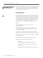
Overview
The PanelView Plus CE SDK provides developers with access to an
extensive set of functions that are specific to the PanelView Plus CE
hardware and extend the standard Windows CE API. These functions,
like the standard Windows CE functions, are implemented in the C
language and can be called directly from C or C++ programs.
ATTENTION
Version Management
The use of undocumented functions and features is strongly
discouraged.
Each release of the PanelView Plus CE SDK and the operating system
has a version number. The version number is in the form of xx.yy.zzz
where xx is the major release, yy is the minor release and zzz is the
build number.
The installed SDK is named PVPlusCE SDK for CE 4.1. The SDK
version number is presented in the Support Info that is viewable in
Control Panel Add/Remove Program. The operating system version is
available in System Properties in the Control Panel.
It is important that the SDK is both current and aligned with the
operating system. The policy for ensuring compatibility relies on the
major release number: A major release of the SDK supports all
versions of the operating system that have the same major release
number. For example, SDK version 02.00.020 is compatible with
operating system version 02.yy.zzz since both are at major release
number 02.
TIP
33
A new SDK is not released with every release of the platform
binary.
Publication 2711P-UM005A-EN-P - March 2007
34
PanelView Plus CE SDK
Visual Basic .NET
Microsoft Visual Studio .NET 2003 is the PC development environment
for Visual Basic .NET applications for Win CE .NET. Visual Studio .NET
2003 can be purchased from Microsoft at
http://msdn.microsoft.com/vstudio/.
The VB .NET execution environment on the device is the .NET
Compact Framework. Visual Studio .NET packages and distributes the
.NET Compact Framework as a .cab file.
ATTENTION
The .NET Compact Framework is not installed on the PanelView
Plus CE device. It is the responsibility of the VB .NET application
developer to provide an installation package for both the VB
.NET application and the .NET Compact Framework.
Both developers and end-users should insure that the .NET Compact
Framework that is installed on the device is the same as that which
was used to develop and test the VB .NET application.
Lastly, there are several essential DLLs that are distributed on the
Accessory CD, Part Number 77159-951-55. Run
InstallFromActiveSync.exe from the CD to install the file set named
DLLs needed by .NET.
Publication 2711P-UM005A-EN-P - March 2007
Chapter
4
PanelView Plus CE-Specific Extensions to the
WinCE API
Overview
This chapter covers these topics:
•
•
•
•
•
•
•
•
•
Watchdog Control
Watchdog control
Hardware watchdog
Software watchdog
System parameters
System timers
Hardware monitor
Keypad
System event log
Recommended PanelView Plus CE mechanisms
The watchdog is a monitor mechanism that automatically resets the
system when there is a loss of control. The hardware watchdog is
enabled by default and must be periodically tagged to keep the entire
system alive. The action of tagging or kicking a watchdog is a widely
used method to insure that system control is intact.
The watchdog service is a DLL and is responsible for tagging the
hardware watchdog. An application can check into the watchdog
service and register itself such that the watchdog service must be
periodically tagged by the application. This latter behavior is referred
to as the software watchdog. Once enabled by an application, the
software watchdog service must be periodically tagged by the
application; otherwise, a timeout occurs and it is assumed that the
application or some underlying software has lost control.
Consequently, an action is initiated that terminates the application or
resets the entire system.
If an application chooses to use the watchdog service, then the
application is also responsible for constructing itself such that some
protection is afforded by the Watchdog. The Watchdog knows when
an application has failed to tag it at the prescribed rate, nothing more.
That is the definition of loss of control within this context, and there
are cases such as tagging the Watchdog too early which are
undetected.
35
Publication 2711P-UM005A-EN-P - March 2007
36
PanelView Plus CE-Specific Extensions to the WinCE API
Hardware Watchdog
Watchdog_Tag
The function combines the ability to enable or disable the hardware
watchdog, tag the watchdog and to optionally set a new timeout value
in the watchdog timer register. It is used in a separate thread within
the watchdog service DLL. Normally, this function would not be used
by an application (exe).
DWORD Watchdog_Tag(DWORD dwTimeout)
Parameters:
dwTimeout
• A value of 0 tags (restarts) the watchdog timer and leaves the
timeout unchanged.
• A value of MAXDWORD (0xFFFFFFFF) disables the watchdog.
• Any other value that is within the range of the timer (50 to
5000), enables the watchdog and sets the timeout in
milliseconds.
Return Values:
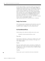
Hardware Watchdog - Return Codes
Value
Description
WATCHDOG_OK
The Watchdog function was successful
WATCHDOG_NOT_PRESENT
Communication with watchdog device failed
WATCHDOG_TIMEOUT_FAILED
Watchdog was tagged, but the requested
timeout value was not set.
Remarks:
If the hardware watchdog is disabled, calling Watchdog_Tag(0) will
always return WATCHDOG_TIMEOUT_FAILED as no current
watchdog timeout value is defined.
If Watchdog_Tag() is called with a timeout value that is out of the
range of the timer then the timeout value currently being used by the
watchdog is left unmodified and WATCHDOG_TIMEOUT_FAILED is
returned. The range of the hardware watchdog timer is 50 to 5,000
milliseconds.
Portability:
Same as the 2711P.
Publication 2711P-UM005A-EN-P - March 2007
PanelView Plus CE-Specific Extensions to the WinCE API
37
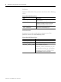
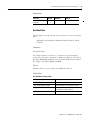
Requirements:
Software Watchdog
Runs On
Version
Defined In
Link To
PanelView Plus CE
RAC6182
All
watchdog.h
watchdog.lib
These functions are used by applications (exes) to register themselves
for watchdog monitoring and to tag the software watchdog.
Watchdog_SW_TagEx
This function registers an application thread for monitoring by the
software watchdog. The function creates a new instance of the
software monitor for the caller thread, sets the timeout value and
defines what happens when a timeout occurs.
DWORD Watchdog_SW_TagEx (DWORD *pdwWDTagID,
DWORD dwTimeout, DWORD dwTimeoutAction)
Parameters:
pdwWDTagID
A pointer to the Watchdog Tag ID value. The watchdog service returns
the value to the caller. The caller should initially set the value to
USE_THREAD_ID when it wants to register a new thread into the
watchdog service. The caller should use the returned value for all
subsequent calls to the watchdog monitor that it was assigned.
Publication 2711P-UM005A-EN-P - March 2007
38
PanelView Plus CE-Specific Extensions to the WinCE API
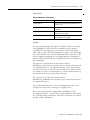
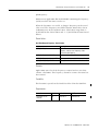
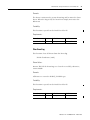
dwTimeout
Timeout in milliseconds. This parameter must be one of the following
values:
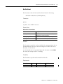
Software Watchdog Timeout Values
Value
Description
WATCHDOG_KICK (Value = 0)
Tags (restarts) the watchdog indicating that the
process is active.
50 – 5000 milliseconds
The watchdog timeout in milliseconds. Once the
watchdog is activated, the caller must tag the
watchdog monitor before a timeout occurs.
WATCHDOG_DISABLE
(Value = MAXDWORD)
Stops the instance of the software watchdog that
corresponds to the Watchdog Tag ID.
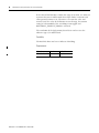
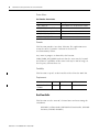
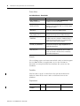
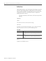
dwTimeoutAction
Determines what action is taken when a timeout occurs. This
parameter must be one of the following values:
Software Watchdog Timeout Actions
Value
Description
WATCHDOG_SYSRESET
Reset the system.
WATCHDOG_APP_STOP
Stop the process. The system will continue to operate.
WATCHDOG_TIMEOUT_PROMPT This is an attribute of the actions:
WATCHDOG_SYSRESET, or WATCHDOG_APP_STOP.
When OR’d with one of these flags, a prompt will be
displayed on the user screen. The prompt must be
acknowledged before the action proceeds.
Publication 2711P-UM005A-EN-P - March 2007
PanelView Plus CE-Specific Extensions to the WinCE API
39
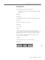
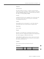
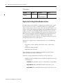
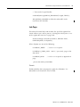
Return Values:
Software Watchdog - Return Codes
Value
Description
WATCHDOG_OK
Success. The watchdog was tagged and/or a new
timeout was set.
WATCHDOG_NOT_PRESENT
Communication with the watchdog could NOT be
established.
WATCHDOG_TIMEOUT_FAILED
The new requested timeout could not be set. The
watchdog was not tagged.
WATCHDOG_INVALID_PARAMETER An invalid parameter was passed to the interface.
The watchdog was not tagged.
Remarks:
The function Watchdog_SW_TagEx() is initially called by the thread
(USE_THREAD_ID) that wants to be monitored by the software
watchdog. The watchdog service determines the thread ID of the
caller, starts a unique dedicated monitor and returns a new WDTagID.
The caller should use the returned WDTagID for all subsequent calls
such as tagging or stopping the watchdog monitor or changing the
timeout. This mechanism permits multiple threads in the same process
to be monitored.
The process is terminated when the timeout action is
WATCHDOG_APP_STOP and a timeout occurs for one of the threads
in a monitored process. The Software Monitor sends a WM_CLOSE
message to the process and if the process does not terminate within
10 seconds, the process is terminated by a call to TerminateProcess()
that terminates the process and all of its threads.
The system is reset when the timeout action is
WATCHDOG_SYSRESET and a timeout occurs for one of the threads
in a monitored process.
If the value of dwTimeout is 0, the watchdog timeout value is not
changed, but if the timer is running, it is tagged (reset).
If the value of dwTimeout is WATCHDOG_DISABLE, then the
watchdog is disabled. A thread that is being monitored must disable
the watchdog before it terminates; otherwise a timeout occurs and the
timeout action is performed.
Publication 2711P-UM005A-EN-P - March 2007
40
PanelView Plus CE-Specific Extensions to the WinCE API
If the value of dwTimeout is within the range 50 to 5000, it is taken to
represent the time in milliseconds that elapse before a timeout and
consequential actions occur. The timer is reset to this value and
started, but if the value of dwTimeout is out of range, the timeout
setting is left unmodified, the watchdog is not tagged and
WATCHDOG_TIMEOUT_FAILED is returned.
The resolution of the high priority thread that watches over the
software tags is 50 milliseconds.
Portability:
The RAC6182 does not have a Software Watchdog.
Requirements:
Publication 2711P-UM005A-EN-P - March 2007
Runs On
Version
Defined In
PanelView Plus CE
All
wdapi.h
PanelView Plus CE-Specific Extensions to the WinCE API
41
Watchdog_SW_Tag
This function tags the software watchdog timer.
DWORD Watchdog_SW_Tag (DWORD dwWDTagID, DWORD
dwTimeout)
Parameters:
dwWDTagID
The Watchdog Tag ID that was assigned by Watchdog_SW_TagEx.
dwTimeout
Timeout in milliseconds. Same as Table .
Return Values:
Same as Table .
Remarks:
Once the application is registered for watchdog monitoring, the
application typically calls Watchdog_SW_Tag () with dwTimeout set to
WATCHDOG_KICK unless the caller wants to change the timeout.
The resolution of the high priority thread that watches over the
software tags is 50 milliseconds.
Portability:
The RAC6182 does not have a Software Watchdog.
Requirements:
Runs On
Version
Defined In
PanelView Plus CE
All
wdapi.h
Publication 2711P-UM005A-EN-P - March 2007
42
PanelView Plus CE-Specific Extensions to the WinCE API
System Parameters
The system maintains information about the system. An application
program can use the functions described here to read or write the
system parameters.
System Parameters and Data Types
The following table enumerates currently defined parameters that can
be accessed with these functions. The table shows the data type,
minimum size, and whether set, get, or both actions are allowed. This
table may be expanded in the future to add new parameter types
without adding new functions.
System Parameters
Parameter
Macro Identifier
Get or
Set
Type
Size
RAM Memory Size
RM_PARAMETER_PHYSICAL_MEMORY_SIZE
Get
DWORD
(Bytes)
4
CPU Speed
RM_PARAMETER_CPU_SPEED_HZ
Get
DWORD
4
Windows CE Version
RM_PARAMETER_WINDOWS_CE_VERSION
Get
WCHAR[80]
80 X 2
Win CE Firmware Build RM_PARAMETER_OS_FIRMWARE_VERSION
Version
Firmware Version
RM_PARAMETER_MICROCONTROLLER_
FIRMWARE_VERSION
Enables Serial Debug RM_PARAMETER_ENABLE_SERIAL_DEBUG_
Messages on
ON_BOOT
Startup/Boot
LCD Brightness
RM_PARAMETER_LCD_BRIGHTNESS
Get
WCHAR[80]
80 X 2
Get
WCHAR[80]
80 X 2
Both
BOOL
4
Both
DWORD
4
MAC ID of on board
Ethernet
Remove mouse cursor
from display
Enables Serial Debug
Messages on
Startup/Boot
Converts virtual to
physical address
Version of BBC
Version of EBC
Display ON Time
Terminal ON Time
Long POST mask
Disable User
Interfaces
RM_PARAMETER_ON_BOARD_
ETHERNET_MAC_ADDRESS
RM_PARAMETER_CURSOR_ENABLED
Get
UCHAR[6]
6
Both
BOOL
4
RM_PARAMETER_ENABLE_SERIAL_DEBUG
Both
BOOL
4
RM_PARAMETER_PHYSICAL_ADDRESS
Get
PUCHAR
4
RM_PARAMETER_BBC_VERSION
RM_PARAMETER_EBC_VERSION
RM_PARAMETER_DISPLAY_ON_TIME
RM_PARAMETER_TERMINAL_ON_TIME
RM_PARAMETER_POST_SELECTIONS
RM_PARAMETER_DISABLE_USER_INPUT
Get
Get
Get
Get
Both
Set
DWORD
DWORD
DWORD
DWORD
UCHAR[16]
BOOL
4
4
4
4
16
4
Publication 2711P-UM005A-EN-P - March 2007
Portability
RAC6182
PanelView Plus CE
RAC6182
PanelView Plus CE
RAC6182
PanelView Plus CE
RAC6182
PanelView Plus CE
RAC6182
PanelView Plus CE
RAC6182
PanelView Plus CE
RAC6182
PanelView Plus CE
RAC6182
PanelView Plus CE
RAC6182
PanelView Plus CE
RAC6182
PanelView Plus CE
RAC6182
PanelView Plus CE
PanelView Plus CE
PanelView Plus CE
PanelView Plus CE
PanelView Plus CE
PanelView Plus CE
PanelView Plus CE
PanelView Plus CE-Specific Extensions to the WinCE API
43
System Parameters
Parameter
Macro Identifier
Get or
Set
Type
Size
Portability
Backlight Status
Enable BBC E-Boot
Enable EBC E-Boot
CIP Serial Number
Persistent Registry
RM_PARAMETER_BACKLIGHT_STATUS
RM_PARAMETER_ENABLE_BBC_EBOOT
RM_PARAMETER_ENABLE_EBC_EBOOT
RM_PARAMETER_CIP_SERIAL_NUMBER
RM_PARAMETER_PERSISTENT_REGISTRY_
PRESENT
RM_PARAMETER_SCREENSAVER_
BRIGHTNESS
RM_PARAMETER_BEZEL_TEMPERATURE_
SENSOR_IS_WORKING
RM_PARAMETER_FACTORY_DEFAULTS
RM_PARAMETER_BOARD_REVISION
Get
Set
Set
Get
Both
BOOL
BOOL
BOOL
DWORD
DWORD
(Bytes)
4
4
4
4
4
PanelView Plus CE
PanelView Plus CE
PanelView Plus CE
PanelView Plus CE
PanelView Plus CE
Both
DWORD
4
PanelView Plus CE
Get
BOOL
4
PanelView Plus CE
Get
Get
BOOL
DWORD
4
4
PanelView Plus CE
PanelView Plus CE
Screensaver
Brightness
Temperature Sensor
Safe Mode Switch
Logic Board Revision
Remarks:
The functions use a model that is similar to device IOCTLs. Functions
take a parameter, the size of data, and a generic buffer. The contents
of the buffer depend on the parameter. The actual size of data that is
Set/Get is returned along with a return code and data.
DWORDrm_Get/SetParameter(DWORD dwParameter, DWORD
*dwSize,VOID *pvData);
The *dwSize parameter passed in indicates the space available in
pvData for a Get or the space of valid data to use for a Set. Upon
success, *dwSize is returned containing the actual amount of data
returned in the buffer for a Get, or the amount of data from the buffer
used for a Set.
The pvData must point to a buffer of large enough size and of correct
size. Parameters which use *pvData as aligned types (e.g. as pointing
to a DWORD or a pointer) must follow the alignment restrictions of
these types. For example, if getting a parameter where *pvData will be
filled with a DWORD value, pvData must be DWORD aligned.
• RM_PARAMETER_DISABLE_USER_INPUT
This parameter prohibits user input via the touchscreen,
keypad and keyboard. This parameter permits an application
to immediately disable user input when the display is lost due
to a back light failure.
Publication 2711P-UM005A-EN-P - March 2007
44
PanelView Plus CE-Specific Extensions to the WinCE API
• RM_PARAMETER_BACKLIGHT_STATUS
This parameter permits an application to monitor the status of
the display backlight. When the value is 0, indicating no
current flow, the application must check the brightness
setting. If LCD_BRIGHTNESS is non-zero, then the display is
ON and failed.
• RM_PARAMETER_ENABLE_BBC_EBOOT
• RM_PARAMETER_ENABLE_EBC_EBOOT
These parameters permit an application to disable or enable
E-Boots at startup. The parameters are maintained in CMOS to
permit exchanges between the OS and non-OS startup code.
• RM_PARAMETER_DISPLAY_ON_TIME
This parameter reads and writes the display on time. The
resolution is 30 minutes and the value is stored in the bezel
EEPROM.
• RM_PARAMETER_TERMINAL_ON_TIME
This parameter reads and writes the terminal on time. The
resolution is 30 minutes and the value is stored in the ATMEL
EEPROM.
• RM_PARAMETER_ CIP_SERIAL_NUMBER
This parameter reads the CIP Serial Number. Each vendor is
responsible for guaranteeing the uniqueness of the serial
number across all of its devices. The value is stored in the
MAC EEPROM and is written via the JTAG interface during
Manufacturing.
• RM_PARAMETER_PERSISTENT_REGISTRY_PRESENT
An application can delete the persistent registry by setting this
parameter to FALSE. The absence of a persistent registry
restores the system to its original state on the next boot.
Applications can poll this parameter to determine if a
persistent registry exists. When TRUE, indicates that a
persistent WinCE registry exists in the binary partition of the
Compact Flash.
• RM_PARAMETER_FACTORY_DEFAULTS
This parameter reads the state of the “default” or “safe mode”
switch. TRUE is returned if the switch was pressed and the
system was started in the “default” or “safe” state.
Publication 2711P-UM005A-EN-P - March 2007
PanelView Plus CE-Specific Extensions to the WinCE API
45
• RM_PARAMETER_BOARD_REVISION
This parameter reads the logic board revision number, which
is managed by a set of 4 pull-up resistors on the board. The
revision number is returned as a simple integer in the range 0
to 15.
Most system parameters are only used to obtain the return
value on get or pass the argument value on set. An exception
is RM_PARAMETER_PHYSICAL_ADDRESS as follows:
• RM_PARAMETER_PHYSICAL_ADDRESS
This parameter allows getting the physical address
corresponding to a virtual address valid in the current process
space. Because of this, the parameter should be passed in
pointing to the desired virtual address. Upon successful return
this value will be replaced with the physical address.
Read or Write System Parameters
These functions permit an application to read or write the System
Parameters.
rm_GetParameter
This function gets a System Parameter.
DWORD rm_GetParameter (DWORD dwParameter, DWORD
*pdwSize, VOID *pvData);
Parameters:
dwParameter
This parameter must be one of the values in Table .
pdwSize
A pointer to a passed value that indicates the number of bytes in the
buffer, pvData. Upon success, dwSize returns the number of bytes
actually returned in the buffer.
pvData
A pointer to a buffer.
Publication 2711P-UM005A-EN-P - March 2007
46
PanelView Plus CE-Specific Extensions to the WinCE API
Return Values:
Get/Set System Parameter - Return Codes
Value
Description
RM_ERROR_OK
Success
RM_ERROR_INVALID_PARAMETER
Bad dwParameter, or NULL dwSize or pvData
RM_ERROR_INVALID_BUFFER_SIZE Buffer size too small for requested parameter.
Remarks:
The buffer at *pvData must be large enough to contain the
information requested and must be aligned as required. For example,
if a request for a parameter will result in *pvData being filled with a
DWORD value, *pvData MUST be DWORD aligned. Please refer to
Table above for the data types associated with the various readable
parameters.
Portability:
Please refer to Table above for an enumeration of which parameters
are supported on the platforms.
Requirements:
Runs On
Version
Defined In
Link To
PanelView Plus CE
RAC6182
All
Miscsystem.h
Miscsystem.lib
rm_SetParameter
This function sets a System Parameter.
DWORD rm_SetParameter (DWORD dwParameter, DWORD
*pdwSize, VOID *pvData);
Parameters:
dwParameter
This parameter must be one of the values in System Parameters on
page 42.
Publication 2711P-UM005A-EN-P - March 2007
PanelView Plus CE-Specific Extensions to the WinCE API
47
pdwSize
A pointer to a caller allocated DWORD whose value represents the
number of bytes at pvData. Upon success, dwSize returns the number
of bytes from the buffer used for a set.
pvData
A pointer to a caller allocated buffer, which contains the data values
for the selected parameter.
Return Values:
Return values are common for both Set and Get functions. See Get/Set
System Parameter - Return Codes above.
Remarks:
The buffer at *pvData must be large enough to contain the
information requested and must be aligned as required. For example,
if the data in *pvData is expected to be a DWORD value, then *pvData
MUST be DWORD aligned.
Please refer to System Parameters on page 42 for the data types
associated with the various writeable parameters.
Portability:
Please refer to System Parameters above for an enumeration of which
parameters are supported on the platforms.
Requirements:
System Timers
Runs On
Version
Defined In
Link To
PanelView Plus CE
RAC6182
All
Miscsystem.h
Miscsystem.lib
The platform hardware provides timers of varying precision,
flexibility, and range. Some of these timers may be used for other
operating-system level purposes such as the reschedule timer
interrupt. However, one or more timers are available for
general-purpose use to application programs. The timers are typically
called user timers and can be configured for one-shot or periodic
operation.
Publication 2711P-UM005A-EN-P - March 2007
48
PanelView Plus CE-Specific Extensions to the WinCE API
A timer number identifies a specific timer. When requesting a timer,
the range of timer numbers is from 0 to MAX_TIMER_NUMBER. In
addition to timer numbers of this range, critical and non-critical timers
can be requested. Critical timers commit a physical resource and
provide very high resolution. Non critical timers share a physical
timer. Currently, there is 1 critical timer and MAX_TIMER_NUMBER
non-critical timers. The attribute USERTIMER_CRITICAL requests a
critical timer. Throughout this API, USERTIMER_CRITICAL must be
or’d with the timer number for a critical timer. Resolution of
non-critical timers is 1ms, accuracy +1/- 0ms. Critical timer resolution
is 50us, +50/-0 us. MAX_TIMER_NUMBER is
implementation-dependent but is guaranteed to be 15 minimum.
Configure Timer Functions
These functions permit an application to determine how many timers
are supported on the system and to claim a specific timer. Once
claimed, the timer is configured, run and eventually released.
UserTimerGetNumberOfTimers
This function gets the number of available timers on the system.
DWORD UserTimerGetNumberOfTimers (void);
Return Value:
Total number of application accessible timers available on the system.
This includes the critical and non-critical timers. The range is 0 to
MAX_TIMER_NUMBER.
Remarks:
Returns the number of timers on the system that are available to the
application. The number returned is the total for ALL applications. If
an application uses a timer, the number of timers available for another
application is one less.
Portability:
This function is specific to PanelView Plus CE or the RAC6182.
Publication 2711P-UM005A-EN-P - March 2007
PanelView Plus CE-Specific Extensions to the WinCE API
49
Requirements:
Runs On
Version
Defined In
Link To
PanelView Plus CE
RAC6182
All
usertimers.h
usertimers.lib
UserTimerClaim
This function is used to claim or release exclusive access to a specific
timer.
DWORD UserTimerClaim (DWORD dwTimerNumber, BOOL
bClaim);
Parameters:
dwTimerNumber
The Timer Number is 0 based; i.e., if 2 timers are present on the
system, they are timer 0 and timer 1. When specifying a critical timer,
the flag USERTIMER_CRITICAL must be or’d with the Timer Number.
The range is 0 to MAX_TIMER_NUMBER.
bClaim
TRUE to claim access to a timer, and FALSE to release it.
Return Values:
UserTimerClaim - Return Codes
Value
Description
USER_TIMER_OK
Successfully claimed or released timer.
USER_TIMER_INVALID_TIMER
The timer number is not valid for the system.
USER_TIMER_NOT_CLAIMED
Another application already claimed the timer so
this application could not claim it.
USER_TIMER_ALREADY_CLAIMED
This application has already claimed this timer.
Publication 2711P-UM005A-EN-P - March 2007
50
PanelView Plus CE-Specific Extensions to the WinCE API
Remarks:
A timer must be claimed for any other function that takes a
TimerNumber as a parameter to be used. A timer must be released to
allow any other application to claim and use the timer.
The mechanism will support a system that has multiple critical timers.
When releasing a timer, any handle created from
UserTimerGetWaitEvent() is closed by this operation. The user should
not close the handle.
Portability:
The RAC6182 does not have a critical timer; hence the attribute
USERTIMER_CRITICAL is not supported on the RAC6182.
Requirements:
Runs On
Version
Defined In
Link To
PanelView Plus CE
RAC6182
All
usertimers.h
usertimers.lib
UserTimerRequestFrequency
This function sets the frequency of a claimed timer.
DWORD UserTimerRequestFrequency (DWORD
dwTimerNumber, DWORD *pdwFrequency);
Parameters:
dwTimerNumber
The Timer Number is 0 based; i.e., if 2 timers are present on the
system, they are timer 0 and timer 1. When specifying a critical timer,
the flag USERTIMER_CRITICAL must be or’d with the Timer Number.
The range is 0 to MAX_TIMER_NUMBER.
Publication 2711P-UM005A-EN-P - March 2007
PanelView Plus CE-Specific Extensions to the WinCE API
51
pdwFrequency
Pointer to an application allocated DWORD containing the frequency
(in Hz) to which the timer is to be set.
When the function is successful, it changes *Frequency to the actual
value used. The *Frequency may differ from the initial value due to
resolution issues in the hardware timer. Valid values range from 1 –
20,000 HZ for the Critical Timer and 1 – 1,000 HZ for the non-Critical
Timers.
Return Values:
UserTimerRequestFrequency - Return Codes
Value
Description
USER_TIMER_OK
The timer has been set to the closest possible
frequency, and the actual frequency used is
returned at pdwFrequency
USER_TIMER_INVALID_TIMER
The timer number is not valid for the system.
USER_TIMER_INVALID_PARAMETER
The requested frequency is NULL or out of range.
USER_TIMER_NOT_CLAIMED
This application has not claimed this timer.
Remarks:
Applications must check the frequency returned and use it in their
counter calculations. The frequency cannot be set once the timer has
been started.
Portability:
This function is specific to the PanelView Plus CE or the RAC6182.
Requirements:
Runs On
Version
Defined In
Link To
PanelView Plus CE
RAC6182
All
usertimers.h
usertimers.lib
Publication 2711P-UM005A-EN-P - March 2007
52
PanelView Plus CE-Specific Extensions to the WinCE API
UserTimerGetWaitEvent
This function registers the application to receive notification of the
timeout event.
DWORD UserTimerGetWaitEvent (DWORD dwTimerNumber,
BOOL bManualReset, HANDLE *phWaitEvent);
Parameters:
dwTimerNumber
The Timer Number is 0 based; i.e., if 2 timers are present on the
system, they are timer 0 and timer 1. When specifying a critical timer,
the flag USERTIMER_CRITICAL must be or’d with the Timer Number.
The range is 0 to MAX_TIMER_NUMBER.
bManualReset
Configures how the event is handled when responding to a Wait….()
operation. The bManualReset parameter specifies whether the event
object automatically resets itself from a signaled state to a
non-signaled state or whether it will require a manual reset.
Consult the Win32 documentation on CreateEvent() for further details.
phWaitEvent
Pointer to a caller allocated HANDLE, in which an event handle will
be stored. NOTE: The handle to the *phWaitEvent should not be
closed by the user. Releasing the timer releases the event handle.
Return Values:
UserTimerGetWaitEvent - Return Codes
Value
Description
USER_TIMER_OK
Successfully created the event handle.
USER_TIMER_INVALID_TIMER
The timer number is not valid for the system.
USER_TIMER_INVALID_PARAMETER
WaitEvent is NULL or a fatal event creation
failure occurred.
USER_TIMER_NOT_CLAIMED
This application has not claimed this timer.
Remarks:
Creates an event handle in *phWaitEvent which may be used in a
WaitForSingleObject() call. This event is set whenever the timer counts
down to zero, allowing interrupt driven timer handling.
Publication 2711P-UM005A-EN-P - March 2007
PanelView Plus CE-Specific Extensions to the WinCE API
53
Calling this API a second time with the same timer number and the
same state for bManualReset will result in the API returning the same
handle as was provided on the first call. If the state of bManualReset is
different, the API will fail.
Portability:
This function is specific to the PanelView Plus CE or the RAC6182.
Requirements:
Runs On
Version
Defined In
Link To
PanelView Plus CE
RAC6182
All
usertimers.h
usertimers.lib
Run Timer Functions
These functions permit an application to start and stop the timer, and
to set the countdown value.
UserTimerSet
This function sets the count of a claimed timer and start timing the
countdown.
DWORD UserTimerSet (DWORD dwTimerNumber, DWORD
dwCount);
Parameters:
dwTimerNumber
The Timer Number is 0 based; i.e., if 2 timers are present on the
system, they are timer 0 and timer 1. When specifying a critical timer,
the flag USERTIMER_CRITICAL must be or’d with the Timer Number.
The range is 0 to MAX_TIMER_NUMBER.
dwCount
A DWORD value that sets the countdown value and starts the timer.
The frequency of the timer is the last frequency returned from
UserTimerRequestFrequency(). The countdown stops and the timer is
triggered at 0.
Publication 2711P-UM005A-EN-P - March 2007
54
PanelView Plus CE-Specific Extensions to the WinCE API
Return Values:
UserTimerSet - Return Codes
Value
Description
USER_TIMER_OK
The countdown was set and the timer started.
USER_TIMER_INVALID_TIMER
The timer number is not valid for the system.
USER_TIMER_INVALID_PARAMETER
dwCount was 0.
USER_TIMER_NOT_CLAIMED
This application has not claimed this timer.
USER_TIMER_SET_FAILED
Unable to set countdown value.
Remarks:
This function provides “one-shot” behavior. The application must
restart the timer if “periodic” behavior is desired. See
UserTimerSetEx() below.
Any count in progress is aborted by this function.
USER_TIMER_SET_FAILED indicates that the count may be beyond
the hardware capabilities of the timers and may be out of range, or
the frequency had not been set.
Portability:
This function is specific to the PanelView Plus CE or the RAC6182.
Requirements:
Runs On
Version
Defined In
Link To
PanelView Plus CE
RAC6182
All
usertimers.h
usertimers.lib
UserTimerSetEx
This function sets the count of a claimed timer and start timing the
countdown.
DWORD UserTImerSetEx (DWORD dwTimerNumber, DWORD
dwCount, DWORD dwMode)
Publication 2711P-UM005A-EN-P - March 2007
PanelView Plus CE-Specific Extensions to the WinCE API
55
Parameters:
dwTimerNumber
The Timer Number is 0 based; i.e., if 2 timers are present on the
system, they are timer 0 and timer 1. When specifying a critical timer,
the flag USERTIMER_CRITICAL must be or’d with the Timer Number.
The range is 0 to MAX_TIMER_NUMBER.
dwCount
A DWORD value that sets the countdown value and starts the timer.
The frequency of the timer is the last frequency returned from
UserTimerRequestFrequency().
dwMode
When FALSE (zero), the timer operates as a one shot. Otherwise,
when TRUE (non zero), the timer operates in periodic mode.
Return Values:
Same as Table .
Remarks:
This API is an extension of the UserTimerSet() function in that it
allows the timer to be configured for periodic or one-shot operation.
Any count in progress is aborted by this function.
USER_TIMER_SET_FAILED indicates that the count may be beyond
the hardware capabilities of the timers and may be out of range, or
the frequency had not been set.
Portability:
This function is specific to the PanelView Plus CE.
Requirements:
Runs On
Version
Defined In
Link To
PanelView Plus CE
All
usertimers.h
usertimers.lib
Publication 2711P-UM005A-EN-P - March 2007
56
PanelView Plus CE-Specific Extensions to the WinCE API
UserTimerGetValue
This function gets the count of a running timer.
DWORD UserTimerGetValue (DWORD dwTimerNumber,
DWORD *pdwCount);
Parameters:
dwTimerNumber
The Timer Number is 0 based; i.e., if 2 timers are present on the
system, they are timer 0 and timer 1. When specifying a critical timer,
the flag USERTIMER_CRITICAL must be or’d with the Timer Number.
The range is 0 to MAX_TIMER_NUMBER.
pdwCount
A Pointer to a caller allocated DWORD where the current count will
be returned.
Return Values:
UserTimerGetValue - Return Codes
Value
Description
USER_TIMER_OK
The timer was running and the count value was
successfully returned.
USER_TIMER_INVALID_TIMER
The timer number is not valid for the system.
USER_TIMER_INVALID_PARAMETER
pdwCount was NULL; i.e. a bad pointer.
USER_TIMER_NOT_CLAIMED
This application has not claimed this timer.
USER_TIMER_NOT_RUNNING
The timer was not running.
Remarks:
Obtains the current countdown value of an active timer. The timer
continues to run.
Portability:
This function is specific to the PanelView Plus CE or the RAC6182.
Publication 2711P-UM005A-EN-P - March 2007
PanelView Plus CE-Specific Extensions to the WinCE API
57
Requirements:
Runs On
Version
Defined In
Link To
PanelView Plus CE
RAC6182
All
usertimers.h
usertimers.lib
UserTimerStop
This function stops a claimed timer.
DWORD UserTimerStop (DWORD dwTimerNumber);
Parameters:
dwTimerNumber
The Timer Number is 0 based; i.e., if 2 timers are present on the
system, they are timer 0 and timer 1. When specifying a critical timer,
the flag USERTIMER_CRITICAL must be or’d with the Timer Number.
The range is 0 to MAX_TIMER_NUMBER.
Return Values:
UserTImerStop - Return Codes
Value
Description
USER_TIMER_OK
The timer was running and was stopped.
USER_TIMER_INVALID_TIMER
The timer number is not valid for the system.
USER_TIMER_NOT_CLAIMED
This application has not claimed this timer.
USER_TIMER_NOT_RUNNING
The timer was not running.
Remarks:
Stops an active countdown in the timer specified by dwTimerNumber
Portability:
This function is specific to the PanelView Plus CE or the RAC6182.
Publication 2711P-UM005A-EN-P - March 2007
58
PanelView Plus CE-Specific Extensions to the WinCE API
Requirements:
Hardware Monitor
Runs On
Version
Defined In
Link To
PanelView Plus CE
RAC6182
All
usertimers.h
usertimers.lib
The PanelView Plus CE platform provides a hardware monitor driver
that can be called by applications to monitor the status of various
board parameters. In addition, the hardware monitor provides
functions to Reboot the board and to query the last reboot reason.
Hardware Monitor Parameters
These platform parameters are monitored by the HardwareMonitor
driver.
• 3-Volt battery voltage
• CPU Temperature
• Display Temperature
Note that the monitored parameters are of fundamentally different
types. Therefore the units of the parameters will vary according to the
parameter being monitored. For example, when an application sets
the warning levels for the 3V-battery voltage, the units of the levels
specified in HardwareMonitor API functions will be Volts. However,
when an application sets display temperature warning levels, the
application must specify temperature in degrees Celsius. Parameter
units are shown Table and described in more detail below for each
API function.
Hardware Monitor Parameters
Publication 2711P-UM005A-EN-P - March 2007
Parameter
Description
Units
MONITOR_ID_BATTERY_VOLTAGE
Monitor the battery voltage that
powers the NVRAM and the RTC.
Volts
MONITOR_ID_CPU_TEMPERATURE
Monitor the CPU temperature.
Degrees
Celsius
MONITOR_ID_DISPLAY_TEMPERATURE
Monitor the display module (LCD)
temperature.
Degrees
Celsius
PanelView Plus CE-Specific Extensions to the WinCE API
59
Hardware Monitor Functions
These functions permit an application to set the warning levels and
register for a warning event. When the event occurs the application
can read the current value of the monitored parameters.
hm_RegisterMonitorWarningEvent
This function registers an application to receive a warning event when
a monitored parameter is above the upper level or below the lower
level bounds.
BOOL hm_RegisterMonitorWarningEvent (DWORD
dwMonitorIDMask, HANDLE *phEventHandle);
Parameters:
dwMonitorIDMask
Bitmask combination of the Table that will return an event to the
application when any parameter enters the warning state.
phEventHandle
Pointer to an application-allocated HANDLE.
Return Values:
Returns TRUE if the monitor warning event has been successfully
registered; otherwise returns FALSE on failure.
Remarks:
Applications that need to be notified when one or more monitored
parameters enter the warning state should register for an event with
this function. The application specifies in dwMonitorIDMask what
monitored parameters should signal an event when entering the
warning state. If this function succeeds, the event handle is returned
to the caller in *phEventHandle and the application can wait on the
event using one of the standard Win32 WaitForxxx() functions. Once
the event is triggered and the application's thread fall through the
WaitForxxx() condition, the application can determine which
parameter is currently in the warning state using the function
hm_GetMonitorWarnings(). If any parameter is still in a warning state,
the application can act accordingly.
Publication 2711P-UM005A-EN-P - March 2007
60
PanelView Plus CE-Specific Extensions to the WinCE API
Note that registering a warning event will not trigger the event if the
monitor is already in the warning state. Applications should either
register their events with hm_RegisterMonitorWarningEvent()
before setting the warning levels with
hm_SetMonitorWarningLevels(), or should check using
hm_GetMonitorLevel() whether the desired monitor parameter is in
range before waiting on the event returned from
hm_RegisterMonitorWarningEvent().
The phEventHandle returned by this function, is a standard Win32
auto reset event handle. However, an application should NOT close
the handle using the Win32 CloseHandle function. Instead the
application should close the handle and un-register the event using
the hm_UnregisterMonitorWarningEvent function.
Portability:
The function prototype is the same as the RAC6182. However, the
MONITOR _ID parameters are different between the platforms.
Requirements:
Runs On
Version
Defined In
Link To
PanelView Plus CE
RAC6182
All
HardwareMonitorAPI.h
HardwareMonitor.lib
hm_UnregisterMonitorWarningEvent
This function cancels the Hardware Monitor registration.
BOOL hm_UnregisterMonitorWarningEvent (HANDLE
hEventHandle);
Parameters:
hEventHandle
The HANDLE that was returned by
hm_RegisterMonitorWarningEvent().
Return Values:
Returns TRUE if the monitor warning event has been successfully
unregistered; otherwise returns FALSE on failure.
Publication 2711P-UM005A-EN-P - March 2007
PanelView Plus CE-Specific Extensions to the WinCE API
61
Remarks:
This function unregisters and frees a warning notification event that
had previously been created using hm_RegisterMonitorWarningEvent.
This function will automatically free hEventHandle, so the application
should not attempt to free it with CloseHandle.
Portability:
The function prototype is the same as the RAC6182. However, the
MONITOR _ID parameters are different between the platforms.
Requirements:
Runs On
Version
Defined In
Link To
PanelView Plus CE
RAC6182
All
HardwareMonitorAPI.h
HardwareMonitor.lib
hm_GetMonitorWarnings
This function gets a bitmask indication of which monitored
parameters are in the warning state.
BOOL hm_GetMonitorWarnings (DWORD *pdwMonitorID);
Parameters:
pdwMonitorID
Pointer to an application-allocated DWORD that returns a bit mask
combination of all monitored parameters currently in the warning
state.
Return Values:
Returns TRUE if the function has been successful; otherwise returns
FALSE on failure.
Publication 2711P-UM005A-EN-P - March 2007
62
PanelView Plus CE-Specific Extensions to the WinCE API
Remarks:
This function returns a bit wise Or’d combination of all monitored
parameters that are currently in the warning state. Note that this
function does not latch any previous warning states that may have
previously triggered warning notification events. Therefore, if a
monitored parameter enters a warning state and triggers a notification
event, it is possible that the parameter has left the warning state
before an application calls this function.
Portability:
The function prototype is the same as the RAC6182. However, the
MONITOR _ID parameters are different between the platforms.
Requirements:
Runs On
Version
Defined In
Link To
PanelView Plus CE
RAC6182
All
HardwareMonitorAPI.h
HardwareMonitor.lib
hm_GetMonitorLevel
This function gets the current value of a specific monitored parameter.
BOOL hm_GetMonitorLevel (DWORD dwMonitorID, DOUBLE
*plfCurrentValue);
Parameters:
dwMonitorID
A value from Table .
plfCurrentValue
Pointer to an application-allocated DOUBLE that returns the current
value for the parameter specified by dwMonitorID.
Return Values:
Returns TRUE if the function is successful; otherwise returns FALSE on
failure.
Publication 2711P-UM005A-EN-P - March 2007
PanelView Plus CE-Specific Extensions to the WinCE API
63
Remarks:
Note that monitor parameters will vary with time, and may oscillate
about a defined upper or lower warning level for a short period.
Therefore, when a warning state event has been triggered, the calling
application should poll the warning status of any monitor sources of
concern (using hm_GetMonitorWarnings) to ensure that the monitor
source remains in a warning state before acting. Note also that to
avoid oscillating events, due to lots of input hysteresis, the hardware
monitor driver will not signal an event when a monitor source leaves
the warning state. Applications must poll the device’s warning state to
determine when/if it resumes normal operation.
Portability:
The function prototype is the same as the RAC6182. However, the
MONITOR _ID parameters are different between the platforms.
Requirements:
Runs On
Version
Defined In
Link To
PanelView Plus CE
RAC6182
All
HardwareMonitorAPI.h
HardwareMonitor.lib
hm_SetMonitorWarningLevels
This function sets the high and low warning levels for a specific
monitored parameter.
BOOL hm_SetMonitorWarningLevels (DWORD dwMonitorID,
DOUBLE IfUpperWarningLevel, DOUBLE IfLowerWarningLevel);
Parameters:
dwMonitorID
A value from Table .
lfUpperWarningLevel
Double precision floating-point value that defines the upper bound of
the monitor parameter during normal operation. If
MONITOR_WARNING_LEVEL_UNDEFINED is specified, the upper
bound is undefined and not used to determine if the parameter enters
the warning state. This is a requirement for some parameters. See
Remarks.
Publication 2711P-UM005A-EN-P - March 2007
64
PanelView Plus CE-Specific Extensions to the WinCE API
lfLowerWarningLevel
Double precision floating-point value that defines the lower bound of
the monitor parameter during normal operation. If
MONITOR_WARNING_LEVEL_UNDEFINED is specified, the lower
bound is undefined and not used to determine if the parameter enters
the warning state. This is a requirement for some parameters. See
Remarks.
Return Values:
Returns TRUE if the warning levels were successfully set; otherwise,
FALSE on failure.
Remarks:
Upper and lower warning levels specify the upper and lower bounds
of the monitored parameter during normal operation. If the parameter
deviates from the specified operating bounds, it enters the warning
state. Upper and lower warning levels are set by default and can be
altered using this function.
The monitor level specified in lfUpperWarningLevel and
lfLowerWarningLevele varies depending on the type of parameter
being monitored.
See Hardware Monitor Parameters for type/units.
The upper warning level for MONITOR_ID_BATTERY_VOLTAGE
must be MONITOR_WARNING_LEVEL_UNDEFINED.
The lower warning level for MONITOR_ID_CPU_TEMPERATURE must
be MONITOR_WARNING_LEVEL_UNDEFINED.
Portability:
The function prototype is the same as the RAC6182. However, the
MONITOR _ID parameters are different between the platforms.
Requirements:
Publication 2711P-UM005A-EN-P - March 2007
Runs On
Version
Defined In
Link To
PanelView Plus CE
RAC6182
All
HardwareMonitorAPI.h
HardwareMonitor.lib
PanelView Plus CE-Specific Extensions to the WinCE API
65
hm_GetMonitorWarningLevels
This function gets the high and low warning levels for a specific
monitored parameter.
BOOL hm_GetMonitorWarningLevels (DWORD dwMonitorID,
DOUBLE *plfUpperWarningLevel, DOUIBLE
*plfLowerWarningLevel);
Parameters:
dwMonitorID
A value from Table .
lfUpperWarningLevel
A pointer to a double precision floating-point value that returns the
upper bound of the monitor parameter during normal operation.
Some parameters return MONITOR_WARNING_LEVEL_UNDEFINED
to indicate that the upper bound is undefined and not used to
determine if the parameter enters the warning state. See Remarks.
lfLowerWarningLevel
A pointer to a double precision floating-point value that defines the
lower bound of the monitor parameter during normal operation. Some
parameters return MONITOR_WARNING_LEVEL_UNDEFINED to
indicate that the lower bound is undefined and not used to determine
if the parameter enters the warning state. This is a requirement for
some parameters. See Remarks.
Return Values:
Returns TRUE if the warning levels were successfully returned;
otherwise, FALSE on failure.
Remarks:
Upper and lower warning levels specify the upper and lower bounds
of the monitored parameter during normal operation. If the parameter
deviates from the specified operating bounds, it enters the warning
state. Upper and lower warning levels are set by default or by
hm_SetMonitorWarningLevels () and can be obtained using this
function.
Publication 2711P-UM005A-EN-P - March 2007
66
PanelView Plus CE-Specific Extensions to the WinCE API
The monitor level specified in lfUpperWarningLevel and
lfLowerWarningLevele varies depending on the type of parameter
being monitored.
See Hardware Monitor Parameters for type/units.
The upper warning level for MONITOR_ID_BATTERY_VOLTAGE is
always MONITOR_WARNING_LEVEL_UNDEFINED.
The lower warning level for MONITOR_ID_CPU_TEMPERATURE is
always MONITOR_WARNING_LEVEL_UNDEFINED.
Portability:
The function prototype is the same as the RAC6182. However, the
MONITOR _ID parameters are different between the platforms.
Requirements:
Runs On
Version
Defined In
Link To
PanelView Plus CE
RAC6182
All
HardwareMonitorAPI.h
HardwareMonitor.lib
Shutdown and Re-Boot Functions
These functions permit an application to boot the system and
determine how the system was last shutdown.
hm_RebootBoard
This function reboots the system.
BOOL hm_RebootBoard (void);
Return Values:
Returns FALSE on failure. Function will not return on success, because
the board will reset immediately.
Publication 2711P-UM005A-EN-P - March 2007
PanelView Plus CE-Specific Extensions to the WinCE API
67
Remarks:
This function performs a reboot of the board. The reboot reason code
is set, caches are flushed and a full reboot is performed, including
reset of hardware chips. Applications should use this function instead
of alternatives such as using KernelIoControl to reset the board.
Portability:
This function is specific to PanelView Plus CE and the RAC6182
hardware.
Requirements:
Runs On
Version
Defined In
Link To
PanelView Plus CE
RAC6182
All
HardwareMonitorAPI.h
HardwareMonitor.lib
hm_GetBootReason
This function gets the reason for the last boot.
DWORD hm_GetBootReason (void);
Publication 2711P-UM005A-EN-P - March 2007
68
PanelView Plus CE-Specific Extensions to the WinCE API
Return Values:
hm_GetBootReason - Return Codes
Value
Description
BOOT_REASON_
WARM_REQUESTED
The System was reset by hm_RebootBoard(). Possibly
called by the Software Watchdog.
BOOT_REASON_
WARM_INTERNAL
The System was reset by some operating system
operation, such as the boot ROM, or a firmware update
that required a reboot.
BOOT_REASON_
WATCHDOG
The hardware watchdog reset the System. Possible
causes are a software or hardware failure.
BOOT_REASON_
COLD_POWER_CYCLE
The board was powered down and the system was
rebooted after enough time for RAM to discharge.
BOOT_REASON_
UNKNOWN
The System was reset but the reason is unknown.
Possible causes are a software or hardware failure, or
simply power down during boot, or an extremely brief
power outage wherein memory endures.
BOOT_REASON_RESET_
BUTTON_OR_BROWNOUT
The System has been rebooted. The board reset button
was pressed or the power supply dropped below an
acceptable voltage level.
BOOT_REASON_
CPU_TOO_HOT
The CPU temperature was too high and the system was
shutdown by the CPU temperature sensor. Possible
causes are a failure of the heat sink or an extremely
high ambient temperature.
Remarks:
The watchdog register and some non-volatile codes in CMOS support
the Last Boot Reason. An application can use this function to
determine its startup behavior based on how the system was last
shutdown.
Portability:
This function is specific to PanelView Plus CE and the RAC6182
hardware. Some of the return codes are different between the
platforms.
Requirements:
Publication 2711P-UM005A-EN-P - March 2007
Runs On
Version
Defined In
Link To
PanelView Plus CE
RAC6182
All
HardwareMonitorAPI.h
HardwareMonitor.lib
PanelView Plus CE-Specific Extensions to the WinCE API
Keypad
69
These functions support front panel connected keypads and the
interface to the Rockwell supplied keypad handler.
Keypad Overview
PanelView Plus CE keypads are intended to function with many of the
same features as normal keyboards, such as supporting typical
modifier mappings of standard keys and supporting configurable
auto-repeat functionality. In addition, the keypad functionality has
some Rockwell proprietary features:
• Support for multiple types of keypads based on an identifier in
the EEPROM. Different keypads may have different scan code to
virtual key mappings.
• Non-standard keys. For example, K1-K16 programmable
function keys or the unique navigation keys formed by the
simultaneous press of ALT with an Up, Down, Left, Right arrow
key. These are non-standard for a keyboard, but are present on
the PanelView Plus CE keypad.
• Support for mapping single key presses into multiple key
macros at the virtual key level.
• Support for other behavior on key presses such as running
programs.
• A ‘single-key’ mode where holding down a key of a certain type
may prevent other types of key presses from being handled.
• A ‘hold-off’ mode where after a key is released, further presses
of it will be ignored for some amount of time.
These features are non-standard keyboard behaviors, so an extension
to the keypad driver is required. Also, the high degree of
configurability needed for keypads, macros, functions, etc. means
even further flexibility by calling up to a higher level keypad handler
outside of the operating system layer.
Publication 2711P-UM005A-EN-P - March 2007
70
PanelView Plus CE-Specific Extensions to the WinCE API
Keypad Driver/Handler Overview
The keypad driver and its companion keypad handler form a system
that addresses the following system design goals:
• The operating system contains a keypad driver. The keypad
driver handles low-level interface, system wide functions; i.e.
determining the model of keypad device, interfacing to the
keypad device to obtain scan codes and up/down status,
mapping from scan code to virtual key, auto-repeat, single-key,
and hold-off functionality.
• The keypad handler handles higher level mappings and
anything requiring greater flexibility and extensibility, such as
mapping virtual keys to other virtual keys, multiple virtual key
macros, memory allocation, storage and configuration of
mapping tables used by the keypad driver, and setting global
configuration options used by the driver.
• The Keypad driver loads the keypad handler and communicates
with the handler via callback functions with defined names.
• The Keypad handler or any other application may also interface
with the keypad driver with streams interface calls to configure
or query it.
• The Keypad driver handles the cases when no keypad or no
keypad handler is present.
• The Keypad handler may defer responsibility for performing
virtual key mappings to the keyboard driver, which will perform
normal modifier mappings as it would for a keyboard.
• The Driver/Handler system allows changes to keypad scan code
to virtual key mappings or individual key attributes without
requiring operating system updates.
• The Driver/Handler system allows the addition of new keypad
models without requiring operating system updates.
Keypad Driver Streams Interface
If the keypad driver successfully loads on boot, control of the keypad
driver by the keypad handler or other applications is accomplished by
a streams driver interface. This means that the driver is opened by
getting a HANDLE to it using a standard CreateFile() call. The device
name to open is defined in keypadapi.h as KEYPAD_DRIVER_PREFIX.
Once an application has opened a HANDLE to the keypad driver in
this manner, it may then control or query the keypad driver using
DeviceIoControl() with IOCTLs defined for the keypad driver. The
supported IOCTLs and their parameters are as follows.
Publication 2711P-UM005A-EN-P - March 2007
PanelView Plus CE-Specific Extensions to the WinCE API
71
• IOCTL_KPD_SET_TYPEMATIC_PARAMS
This sets the typematic rate – whether auto-repeat is enabled
and if so, the delay and repeat period in milliseconds. This
information is maintained for the keypad independently of
the keyboard auto-repeat settings, so is not controlled by nor
does it affect the settings under control panel, keyboard. This
IOCTL requires an input buffer of a
PKPD_PARAM_TYPEMATIC of size
sizeof(KPD_PARAM_TYPEMATIC).
• IOCTL_KPD_QUERY_TYPEMATIC_PARAMS
This gets the current typematic rate information for the
keypad. This IOCTL requires an output buffer of a
PKPD_PARAM_TYPEMATIC of size
sizeof(PD_PARAM_TYPEMATIC).
• IOCTL_KPD_SET_SINGLE_KEY_MODE
This sets the single key mode information. It requires an input
buffer of a PKPD_PARAM_SINGLE_KEY_MODE of size
sizeof(KPD_PARAM_SINGLE_KEY_MODE).
• IOCTL_KPD_QUERY_SINGLE_KEY_MODE
This gets the current single key mode information. It requires
an output buffer of a PKPD_PARAM_SINGLE_KEY_MODE of
size sizeof(KPD_PARAM_SINGLE_KEY_MODE).
• IOCTL_KPD_SET_HOLD_OFF_MODE
This sets the key hold-off mode. It requires an input buffer of
a PKPD_PARAM_HOLD_OFF_MODE of size
sizeof(KPD_PARAM_HOLD_OFF_MODE).
• IOCTL_KPD_QUERY_HOLD_OFF_MODE
This gets the key hold-off mode. It requires an output buffer
of a PKPD_PARAM_HOLD_OFF_MODE of size
sizeof(KPD_PARAM_HOLD_OFF_MODE).
Portability:
This function is specific to the RAC6182 and the PanelView Plus CE.
Publication 2711P-UM005A-EN-P - March 2007
72
PanelView Plus CE-Specific Extensions to the WinCE API
Requirements:
Runs On
Version
Defined In
PanelView Plus CE
RAC6182
All
keypadapi.h
khapi.h
RAC6182OEMVKeys.h
Link To
Registry Keys for Keypad Driver/Handler Interface
The operating system provides a simple keypad handler stub, which
may be used in cases where custom behavior such as application
launch and macros are not necessary. This stub provides simple scan
code to virtual code mapping and global setting information from the
registry, and defers all mapping from the virtual key level up to the
keyboard driver’s default mappings. The registry keys khstub uses to
obtain keypad mapping and other information are documented here
in case keypad handler and keypad configuration application
developers wish to use the same keys. It is not necessary to do so, but
will probably prove to be a convenience.
Note that if a registry entry is not found, khstub uses the following
defaults:
• Typematic repeat enabled, initial delay 500ms, repeat delay
33ms
• Single-key mode disabled
• Hold-off mode disabled
These defaults are specific to khstub so another keypad handler
implementation may do this differently.
Global key setting information is listed here by key and value.
• [HKEY_LOCAL_MACHINE\Drivers\BuiltIn\Keypad\Params\Typ
ematicRepeat]
Enabled REG_DWORD which is 1 for enabled, 0 for disabled
RepeatDelay REG_DWORD of initial repeat delay in ms.
RepeatRate REG_DWORD of subsequent repeat delay in ms.
Publication 2711P-UM005A-EN-P - March 2007
PanelView Plus CE-Specific Extensions to the WinCE API
73
• [HKEY_LOCAL_MACHINE\Drivers\BuiltIn\Keypad\Params\Sing
leKeyMode]
Enabled REG_DWORD which is 1 for enabled, 0 for disabled
AbortEnabled REG_DWORD which is 1 for enabled, 0 for
disabled
• [HKEY_LOCAL_MACHINE\Drivers\BuiltIn\Keypad\Params\Hol
doffMode]
Enabled REG_DWORD which is 1 for enabled, 0 for disabled
HoldoffTime REG_DWORD of time in ms. for key hold-off
System Event Log
The PanelView Plus CE platform provides a System Event Log wherein
applications can record system Events that are viewable in the
Hardware Monitor Properties applet in Control Panel. An Event can be
any condition that may be of interest to the user. In the PanelView
Plus CE, the Event log is implemented as the file
\storage card\Event.Log and as such is supported by all the standard
file amenities. It is fixed in size by EVENT_LOG_MAX_RECORDS and
holds at least 32 of the most recently logged Events. The Event Log
object wraps the Event Log such that applications need not be
concerned about creating, opening or closing the file.
Event Data Structure
This structure describes the System Event Record.
typedef struct Event_record {
UINT nIndex;
UINT nType;
SYSTEMTIME LocalTime;
TCHAR szDescription[MAX_DESCRIPTION];
} EVENT;
Publication 2711P-UM005A-EN-P - March 2007
74
PanelView Plus CE-Specific Extensions to the WinCE API
Members
nIndex
The record index.
nType
Event Type
Event Types
Value
Description
EVENT_UNUSED
Event record is empty; i.e. unused.
EVENT_WARNING
Event is a warning condition; e.g. low battery.
EVENT_ERROR
Event is an error condition; CPU Over-temperature.
EVENT_INFO
Event is information only; e.g. Last Boot Reason
LocalTime
Time and Date Stamp
szDescription
A text string that describes the Event.
Log New Event
This function writes a new Event to the Event Log.
void LogNew Event(LPCTSTR szEventDescription, int
nEventType);
Parameters:
szEventDescription
A pointer to a text string that describes the Event.
nEventType
This parameter must be one of the values in Table .
Publication 2711P-UM005A-EN-P - March 2007
PanelView Plus CE-Specific Extensions to the WinCE API
75
Remarks:
The Event is written to the system Event Log and becomes the latest
Event. When the Log is full, the latest Event simply over-writes the
oldest one
Portability:
This function is specific to the PanelView Plus CE.
Requirements:
Runs On
Version
Defined In
Link To
PanelView Plus CE
All
EventLog.h
EventLog.lib
Clear Event Log
This function clears all Events from the Event log.
BOOL ClearEvents (void);
Return Values:
Returns TRUE if the Event Log was cleared successfully; otherwise,
returns FALSE.
Remarks:
All Events are set to the EVENT_UNUSED type.
Portability:
This function is specific to the PanelView Plus CE.
Requirements:
Runs On
Version
Defined In
Link To
PanelView Plus CE
All
EventLog.h
EventLog.lib
Publication 2711P-UM005A-EN-P - March 2007
76
PanelView Plus CE-Specific Extensions to the WinCE API
Get Last Event
This function reads the last or newest Event from the Event log.
DWORD GetLastEvent (EVENT *pEvent);
Parameters:
pEvent
A pointer to an EVENT structure.
Return Values:
GetLastEvent - Return Codes
Value
Description
EVENT_SUCCESS
The last; i.e. the most recent, Event was read
successfully and returned to the EVENT structure.
EVENT_ FILE_EMPTY
No Event was returned The Event log is empty.
EVENT_FAIL
No Event was returned. The operation failed.
Remarks:
This function is typically used to establish the starting position for an
iteration loop that traverses the Event Long in the newest to oldest
direction; for example, last to first.
After establishing the starting position with this function, use
GetNextEvent() in a iteration loop with direction set to PRIOR. The
time/date stamps will be descending.
Portability:
This function is specific to the PanelView Plus CE.
Requirements:
Publication 2711P-UM005A-EN-P - March 2007
Runs On
Version
Defined In
Link To
PanelView Plus CE
All
EventLog.h
EventLog.lib
PanelView Plus CE-Specific Extensions to the WinCE API
77
Get First Event
This function reads the first or oldest Event from the Event log.
DWORD GetFirstEvent (EVENT*pEvent);
Parameters:
pEvent
A pointer to an EVENT structure.
Return Values:
GetFirstEvent - Return Codes
Value
Description
EVENT_SUCCESS
The first or oldest Event was read successfully and
returned to the structure at pEvent.
EVENT_ FILE_EMPTY
No Event was returned The Event log is empty.
EVENT_FAIL
No Event was returned. The operation failed.
Remarks:
This function is typically used to establish the starting position for an
iteration loop that traverses the Event Long in the oldest to newest
direction; i.e. first to last.
Use GetNextEvent() in a iteration loop with direction set to AFTER.
The time/date stamps will be ascending.
Portability:
This function is specific to the PanelView Plus CE.
Requirements:
Runs On
Version
Defined In
Link To
PanelView Plus CE
All
EventLog.h
EventLog.lib
Publication 2711P-UM005A-EN-P - March 2007
78
PanelView Plus CE-Specific Extensions to the WinCE API
Get Next Event
This function reads the “next” Event from the Event Log in a specified
direction. This function permits an application to traverse the Event
Log in an ordered fashion. If the Event Log is traversed such that the
record after the end or the record before the first is sought then
EVENT_EOF will be returned.
DWORD GetNextEvent (UINT nIndex, UINT nDirection, EVENT
*pEvent);
Parameters:
nIndex
The index to an Event record in the Event Log.
nDirection
Determines the direction for locating the “next” record in the Event
Log. This parameter must be one of the following values:
Event Types
Value
Description
PRIOR
Get the Event that occurred immediately prior to Event[nIndex]. The
returned Event will have an earlier time stamp than the Event at
nIndex.
AFTER
Get the Event that occurred immediately after Event[nIndex]. The
returned Event will have an later time stamp than the Event at
nIndex.
pEvent
A pointer to an EVENT structure.
Publication 2711P-UM005A-EN-P - March 2007
PanelView Plus CE-Specific Extensions to the WinCE API
79
Return Values:
GetNextEvent - Return Codes
Value
Description
EVENT_SUCCESS
The Event was read successfully and returned to the
structure at pEvent.
EVENT_EOF
No Event was returned The record index is at the end of
the file or at an empty Event.
EVENT_FAIL
No Event was returned. The operation failed.
Remarks:
This first time GetNextEvent() is called, the parameter nIndex is
typically the index to the Event that was returned by calling
GetFirstEvent() or GetLastEvent(). Subsequent calls should provide the
index that was returned in the preceding call to GetNextEvent().
If the return code is EVENT_SUCCESS, the next Event in the specified
direction was returned to the Event structure at pEvent.
EVENT_EOF is returned when the Event Log has determined that it is
at the end of the file. An empty record is interpreted as the end of file.
Is it recommended that GetFirstEvent()or GetLastEvent() always be
called before entering an iteration loop using GetNextEvent();
otherwise, the starting index will be misplaced. Another consideration
is that an empty Event Log returns EVENT_EOF; whereas,
GetFirstEvent() or GetLastEvent() will properly return EVENT_
FILE_EMPTY when the file is empty.
Portability:
This function is specific to the PanelView Plus CE.
Requirements:
Runs On
Version
Defined In
Link To
PanelView Plus CE
All
EventLog.h
EventLog.lib
Publication 2711P-UM005A-EN-P - March 2007
80
PanelView Plus CE-Specific Extensions to the WinCE API
Recommended PanelView
Plus CE Mechanisms
These Win32 mechanisms have specific utility or packaging for the
PanelView Plus CE platform. Some are simply not handled properly
by the Platform Builder exporter and the PanelView Plus CE header
file is described here for convenience.
Disable Keypad Handler
The PanelView Plus CE device supports a mechanism known as the
keypad handler that permits the F-keys and K-keys on the keypad to
be remapped to emulate alternate keys and/or multiple key presses.
Refer to Keypad Overview on page 69. An application or a dialog that
relies on unmapped keys should send a window message to the
keypad handler to turn off the keypad mappings. Subsequently, the
keypad handler can be re-enabled using a similar message.
Remarks
Call RegisterWindowMessage() with the value WM_
KEYPAD_HANDLER.
Call SendNotifyMessage() with the message identifier that was
returned from RegisterWindowMessage() to disable and then to
enable keypad mappings.
The first parameter enables keypad mappings when TRUE and
disables the mappings when FALSE. The second parameter is ignored.
Restarting the system will restart the keypad handler, which enables
the keypad mappings.
Behavior of the fixed (non-programmable) keys is unaffected.
The following code snip illustrates the mechanism:
UINT msgID =
RegisterWindowMessage(WM_KEYPAD_HANDLER);
// This dialog requires an unmapped keypad. Turn off the
keypad handler
SendNotifyMessage( HWND_BROADCAST, msgID, FALSE, 0 );
Publication 2711P-UM005A-EN-P - March 2007
PanelView Plus CE-Specific Extensions to the WinCE API
81
// Turn on the keypad handler.
SendNotifyMessage(HWND_BROADCAST, msgID, TRUE,0);
WM_KEYPAD_HANDLER is defined in othersdk.h in the
PanelView Plus CE SDK.
Lock Pages
This Win32 function locks into memory the specified region of the
virtual address space of the process, ensuring that subsequent access
to the region does not incur a page fault.
BOOL LockPages (LPVOID lpvAddress, DWORD cbSize,
PDWORD pPFNs, int fOptions);
Where fOpions are one of the following:
LOCKFLAG_WRITE
// write access required
LOCKFLAG_QUERY_ONLY 0x002 // query only, page in but
don't lock
LOCKFLAG_READ
page
// read access required (as opposed to
present but PAGE_NOACCESS)
Remarks
Platform Builder does not properly export the definitions. Use
othersdk.h in the PanelView Plus CE SDK.
Publication 2711P-UM005A-EN-P - March 2007
82
PanelView Plus CE-Specific Extensions to the WinCE API
UnLock Pages
This Win32 function unlocks a specified range of pages in the virtual
address space of a process, enabling the system to swap the pages out
if necessary.
BOOL UnlockPages (LPVOID lpvAddress, DWORD cbSize);
Remarks
Platform Builder does not properly export the definition. Use
othersdk.h in the PanelView Plus CE SDK.
SetSystemMemoryDivision
This Win CE function sets the amount of DRAM allocated to the
system.
DWORD SetSystemMemoryDivision (DWORD dwStorePages);
Remarks
Total DRAM installed can be obtained with a call to
rm_GetParameter() using
RM_PARAMETER_PHYSICAL_MEMORY_SIZE as the first argument.
This memory is divided into two logical partitions, one for the object
Store (RAMDISK), and one for system memory. The memory available
for the Object Store will be the total amount of memory less the
amount allocated to the system. The number of 4KB pages to be
allocated to the system is specified by dwStorePages.
Publication 2711P-UM005A-EN-P - March 2007
Chapter
5
Device Drivers
Overview
This chapter provides an overview of developing a device driver and
sample code.
Developing a Device Driver
This discussion considers a device driver that implements the Win CE
standard stream driver interface. Ideally, the stream driver interface
should be the only interface used by applications, services, COM
servers, and other drivers to communicate with hardware.
Furthermore, a device driver is the only supported interface to the
hardware.
The following discussion and code samples provide preferred
methods for driver development. In an ever-changing CE OS
landscape, using these recommended methods should help maintain
compatibility with future platform releases.
It is recommended that the PCI or ISA bus enumerators be used to get
configuration data for PCI or ISA devices. These enumerators collect
configuration data from the device and deposit it in the registry. Using
helper functions from the Driver Development Kit (DDK) the
configuration information is easily obtained from the registry.
Additionally these enumerators also manage the IO and Resource
space, which helps protect your driver and hardware from access by
other modules.
83
Publication 2711P-UM005A-EN-P - March 2007
84
Device Drivers
The following flow chart illustrates the preferred method for driver
initialization.
Init
Initialize global data
with default info.
Is the
PCI Bus
Enumerator data
available in the
registry?
No
Yes
Is there
registry data
somewhere
else?
No
Yes
Get PCI Bus Enumerator
registry data
Get registry data from
another location
Yes
Is the
IRQ
valid?
No
Use DDK Hal calls to get the IRQ
from the PCI device directly.
No
Query the Hal for a SYSINTR
associated with the IRQ.
Yes
Load the chain handler
Yes
Is the
SYSINTR
valid?
Yes
Is the
ISR Chain Handler
Required?
No
Initialize IRQ and additional
driver resources.
Return
Publication 2711P-UM005A-EN-P - March 2007
Set IRQ and SYSINTR
to invalid defaults
Device Drivers
Sample Code
85
The code sample describes the preferred process for driver
initialization and provides a good starting point that can be used as a
model for actual production code. Though this code will compile,
none of the constant data is valid for any real device, they are just
placeholders for a developer to replace with proper values.
Additionally, this driver only implements the XXX_Init and
XXX_Deinit entry points.
The sample driver code illustrates several methods to obtain IRQ and
SYSINTR data from the platform. When all other sources are
exhausted this implementation will finally use pre-defined,
hard-coded values. A driver that uses this method is more easily
migrated to platforms that do not support specific features. For
example; if the platform does not have a PCI bus enumerator, but
does support the DDK Hal PCI functions, this driver implementation
would still be able to get the needed configuration data. Then when
the platform is changed and the PCI bus enumerator is supported, no
re-design of the driver is needed.
////////////////////////////////////////////////////////////////////
//
// File: driver.c
//
// Example of the preferred initialization processes used in
// CE platform stream based device driver development.
//
/////////////////////////////////////////////////////////////////////
#include <windows.h>
#include <pkfuncs.h>
#include <ceddk.h>
#include <ddkreg.h>
#include <nkintr.h>
#include <giisr.h>
////////////////////////////////////////////////////////////////////
//
// USAGE Build switches
//
// Defining DRV_USE_IO will use x86 port IO instructions when needed.
// Defining DRV_USE_PCI will invoke PCI DDK calls to assist initialization.
// Defining DEV_USE_ISR will cause the driver to attempt to
// initialize a Chained ISR handler.
//
/////////////////////////////////////////////////////////////////////
Publication 2711P-UM005A-EN-P - March 2007
86
Device Drivers
#define DRV_USE_IO
#define DRV_USE_PCI
#define DRV_USE_ISR
// set to use port IO
// set to use PCI DDK
// set to invoke ISR handler
/////////////////////////////////////////////////////////////////////
//
// GIISR constants
//
// Refer to Microsoft documentation on the GIISR chain handler DLL for a
// detailed description of these parameters
//
// NOTE: these are example values.
//
/////////////////////////////////////////////////////////////////////
#define DRV_PORT_ADDR
0xb0000000
#define DRV_PORT_SIZE
sizeof(DWORD)
#define DRV_IRQ
0x1
#define DRV_SYSINTR
0x10
#if defined (DRV_USE_PCI)
#define DRV_VENDOR_ID
0x1010
#define DRV_DEVICE_ID
0x0101
/////////////////////////////////////////////////////////////////////
//
// PCI constants
//
// Refer to Microsoft documentation on PCI device drivers for a
// detailed description of these parameters
//
// NOTE: these are example values.
//
/////////////////////////////////////////////////////////////////////
#define DRV_DEVICE_NUM 1
#define DRV_FUNC_NUM
0
#define DRV_BUS_NUM
0
#endif // defined (DRV_USE_PCI)
#define DRV_INTSTAT_PENDING 0x1
/////////////////////////////////////////////////////////////////////
//
// DEBUG ZONE constants
//
// Refer to Microsoft documentation on DEBUG ZONES for a
// detailed description of these parameters
//
/////////////////////////////////////////////////////////////////////
#define ZONE_INIT
#define ZONE_FUNC
#define ZONE_WARN
#define ZONE_ERROR
DEBUGZONE(0)
DEBUGZONE(13)
DEBUGZONE(14)
DEBUGZONE(15)
//
// Macro used to call the HAL IOCTL to get a SYSINTR
// assigned to a IRQ (can be used to create the assignment also)
//
#define REQUEST_SYSINTR(i,s) \
Publication 2711P-UM005A-EN-P - March 2007
Device Drivers
87
\
KernelIoControl(IOCTL_HAL_REQUEST_SYSINTR, \
(PVOID)&i,sizeof(i),(PVOID)&s, \
sizeof(s),NULL)
//
// DEBUG zone text labels use by the platform debugger
//
#ifdef DEBUG
DBGPARAM dpCurSettings = {
TEXT("TestDrv"), {
TEXT("Init"),TEXT(""),TEXT("Stats"),TEXT(""),
TEXT(""),TEXT(""),TEXT(""),TEXT(""),
TEXT(""),TEXT(""),TEXT(""),TEXT(""),
TEXT(""),TEXT("Function"),TEXT("Warning"),TEXT("Error") },
0x00000000
};
#endif
/////////////////////////////////////////////////////////////////////
//
// Example driver global data structure
//
// This structure is used to store information for this DLLs instance
// only. All driver CreateFile() calls create separate "Open"
// instances. The driver should be written so that each of these
// open instances should be able to access the global instance data.
//
/////////////////////////////////////////////////////////////////////
typedef struct
{
BOOL bExitThread;
GIISR_INFO Gii;
DDKISRINFO Dii;
HANDLE hEvent;
HANDLE hThread;
DWORD dwThreadId;
#if defined(DRV_USE_ISR)
HANDLE hIsrHandler;
#endif // defined(DRV_USE_ISR)
#if defined(DRV_USE_PCI)
DDKWINDOWINFO Dwi;
DDKPCIINFO Dpi;
#endif // defined(DRV_USE_PCI)
} DRV_DATA, *PDRV_DATA;
/////////////////////////////////////////////////////////////////////
//
// Function Prototypes
//
/////////////////////////////////////////////////////////////////////
#if defined(DRV_USE_PCI)
static BOOL
PciFindDevice(
LPCTSTR szBaseInstance,
USHORT VendorId,
USHORT DeviceId,
PDDKWINDOWINFO pdwi,
Publication 2711P-UM005A-EN-P - March 2007
88
Device Drivers
PDDKISRINFO pdii,
PDDKPCIINFO pdpi
);
#endif // defined(DRV_USE_PCI)
DRV_Deinit(
DWORD hDeviceContext
);
static DWORD WINAPI
IstThreadProc(
LPVOID lpParameter
);
/////////////////////////////////////////////////////////////////////
//
// DRV_Init()
//
// Refer to Microsoft documentation on Device Driver Development for a
// detailed description of this function and its parameters.
//
// NOTE: This function will attempt to initialize a NOP driver that
// will be referred to as "DRV:". If a non-recoverable error occurs
// during the INIT phase this function will call DRV_Deinit(). This
// function is safe to call multiple times. This is done to insure
// proper driver cleanup.
//
/////////////////////////////////////////////////////////////////////
DWORD
DRV_Init(
DWORD dwContext
)
{
#if defined(DRV_USE_PCI)
DWORD dwErr;
#endif // defined(DRV_USE_PCI)
PDRV_DATA pDrvData = NULL;
DEBUGMSG(ZONE_FUNC, (TEXT("DRV_Init+\r\n")));
//
// first, create a memory block to store this drivers' global instance data
//
if (NULL == (pDrvData = (PDRV_DATA)LocalAlloc(LMEM_FIXED | LMEM_ZEROINIT,
sizeof(DRV_DATA))))
{
ERRORMSG(1,(_T("DRV_Init: LocalAlloc failed!\r\n")));
DEBUGMSG(ZONE_FUNC, (TEXT("DRV_Init-\r\n")));
return (0);
}
//
// fill in global info
//
pDrvData->bExitThread = FALSE;
pDrvData->hEvent = INVALID_HANDLE_VALUE;
pDrvData->hThread = INVALID_HANDLE_VALUE;
pDrvData->Gii.SysIntr = 0;
Publication 2711P-UM005A-EN-P - March 2007
Device Drivers
89
pDrvData->Gii.CheckPort = TRUE;
#if defined(DRV_USE_IO)
pDrvData->Gii.PortIsIO = TRUE;
#else // defined(DRV_USE_IO)
pDrvData->Gii.PortIsIO = FALSE;
#endif // defined(DRV_USE_IO)
#if defined(DRV_USE_ISR)
pDrvData->Gii.UseMaskReg = FALSE;
pDrvData->Gii.PortAddr = DRV_PORT_ADDR;
pDrvData->Gii.PortSize = DRV_PORT_SIZE;
pDrvData->Gii.Mask = DRV_INTSTAT_PENDING;
#endif // defined(DRV_USE_ISR)
#if defined(DRV_USE_PCI)
//
// Find the PCI devices driver information placed in
// the registry by the PCIBus enumerator.
//
if (!(dwErr = PciFindDevice((TCHAR *)dwContext,
DRV_VENDOR_ID,
DRV_DEVICE_ID,
&pDrvData->Dwi,
&pDrvData->Dii,
&pDrvData->Dpi)))
{
ERRORMSG(1,(_T("DRV_Init: call to PciFindDevice() failed [0x%08x]!\r\n"),dwErr));
DEBUGMSG(ZONE_FUNC, (TEXT("DRV_Init-\r\n")));
DRV_Deinit((DWORD)pDrvData);
return (0);
}
#else // defined(DRV_USE_PCI)
//
// Here you may want to load registry values from
// another location
//
#endif // defined(DRV_USE_PCI)
//
// If the IRQ value has not been set yet, try
// alternate methods to setting it.
//
if (0 == pDrvData->Dii.dwIrq)
{
#if defined(DRV_USE_PCI)
PCI_COMMON_CONFIG Pcc;
PCI_SLOT_NUMBER Sn;
DWORD dwLength;
#endif // defined(DRV_USE_PCI)
// Set a default value from a constant.
//
pDrvData->Dii.dwIrq = DRV_IRQ;
#if defined(DRV_USE_PCI)
Publication 2711P-UM005A-EN-P - March 2007
90
Device Drivers
//
// Attempt to use lower level DDK function to get
// information directly from the PCI controller.
//
/////////////////////////////////////////////////////
//
// Normally you would code a loop here that would be
// used to search the PCI Bus for the desired device,
// but for this example we are just going to assume
// we know the BUS, Slot and Function number.
//
//////////////////////////////////////////////////////
Sn.u.bits.DeviceNumber = DRV_DEVICE_NUM;
Sn.u.bits.FunctionNumber = DRV_FUNC_NUM;
// DDK call to query for PCI information
dwLength = HalGetBusDataByOffset(PCIConfiguration, DRV_BUS_NUM,
Sn.u.AsULONG,
&Pcc, 0,
sizeof(PCI_COMMON_CONFIG));
//
// check to see if the call was successful
//
if (sizeof(PCI_COMMON_CONFIG) == dwLength)
{
pDrvData->Dii.dwIrq = Pcc.u.type2.InterruptLine;
}
else
{
DEBUGMSG(ZONE_INIT,(_T("DRV_Init: HalGetBusDataByOffset()")
_T(" call failed!\r\n")));
}
#endif // defined(DRV_USE_PCI)
}
//
// If the SYSINTR has not been assigned yet, try and ask the HAL
// if it has or can assign a SYSINTR for you.
//
if (0 == pDrvData->Gii.SysIntr)
{
if (!REQUEST_SYSINTR(pDrvData->Dii.dwIrq,pDrvData->Gii.SysIntr))
{
pDrvData->Gii.SysIntr = DRV_SYSINTR;
}
}
Publication 2711P-UM005A-EN-P - March 2007
Device Drivers
91
#if defined(DRV_USE_ISR)
//
// If a DLL name was not assigned yet, just default the name for
// use with the Microsoft GIISR chain handler.
//
if (NULL == pDrvData->Dii.szIsrDll)
{
_tcscpy(pDrvData->Dii.szIsrDll,_T("giisr.dll"));
}
//
// If a ISRHandler name was not assigned yet, just default the name for
// use with the Microsoft GIISR chain handler.
//
if (NULL == pDrvData->Dii.szIsrHandler)
{
_tcscpy(pDrvData->Dii.szIsrHandler,_T("IsrHandler"));
}
//
// Install ISR handler if there is one
//
pDrvData->hIsrHandler = LoadIntChainHandler(pDrvData->Dii.szIsrDll,
pDrvData->Dii.szIsrHandler,
(BYTE)pDrvData->Dii.dwIrq);
if (INVALID_HANDLE_VALUE == pDrvData->hIsrHandler)
{
ERRORMSG(1,(_T("DRV_Init: Couldn't install ISR handler!\r\n")));
DEBUGMSG(ZONE_FUNC, (TEXT("DRV_Init-\r\n")));
DRV_Deinit((DWORD)pDrvData);
return (0);
}
///////////////////////////////////////////////////////////////////////
//
// Communicate with the chain handler and pass to it the info needed to
// detect a IRQ intended for this device.
//
// NOTE: This code assumes the chain handler conforms to the exact same
//
interface as the GIISR.
//
/////////////////////////////////////////////////////////////////////////////
if (!KernelLibIoControl(pDrvData->hIsrHandler, IOCTL_GIISR_INFO,
&pDrvData->Gii, sizeof(GIISR_INFO), NULL, 0, NULL))
{
ERRORMSG(1,(_T("DRV_Init: KernelLibIoControl call failed!\r\n")));
DEBUGMSG(ZONE_FUNC, (TEXT("DRV_Init-\r\n")));
DRV_Deinit((DWORD)pDrvData);
return (0);
}
#endif // defined(DRV_USE_ISR)
//
// Create the IST event.
//
Publication 2711P-UM005A-EN-P - March 2007
92
Device Drivers
if (INVALID_HANDLE_VALUE == (pDrvData->hEvent = CreateEvent(NULL,FALSE,FALSE,NULL)))
{
ERRORMSG(1,(TEXT("DRV_Init: CreateEvent call failed.\r\n")));
DEBUGMSG(ZONE_FUNC, (TEXT("DRV_Init-\r\n")));
DRV_Deinit((DWORD)pDrvData);
return (0);
}
//
// Now initialize the interrupt so that the kernel starts sending
// events for this IRQ
//
if (!InterruptInitialize(pDrvData->Gii.SysIntr,pDrvData->hEvent,NULL,0))
{
ERRORMSG(1,(TEXT("DRV_Init: InterruptInitialize call failed.\r\n")));
DEBUGMSG(ZONE_FUNC, (TEXT("DRV_Init-\r\n")));
DRV_Deinit((DWORD)pDrvData);
return (0);
}
//
// Create the IST thread.
//
if (INVALID_HANDLE_VALUE ==
(pDrvData->hThread = CreateThread(NULL,0,IstThreadProc,pDrvData,
0,&pDrvData->dwThreadId)))
{
ERRORMSG(1,(TEXT("DRV_Init: CreateThread() call failed.\r\n")));
DEBUGMSG(ZONE_FUNC, (TEXT("DRV_Init-\r\n")));
DRV_Deinit((DWORD)pDrvData);
return (0);
}
DEBUGMSG(ZONE_FUNC, (TEXT("DRV_Init-\r\n")));
return ((DWORD)pDrvData);
}
/////////////////////////////////////////////////////////////////////
//
// DRV_Deinit()
//
// Refer to Microsoft documentation on Device Driver Development for a
// detailed description of this function and its parameters
//
/////////////////////////////////////////////////////////////////////
BOOL
DRV_Deinit(
DWORD hDeviceContext
)
{
PDRV_DATA pDrvData = (PDRV_DATA)hDeviceContext;
DEBUGMSG(ZONE_FUNC, (TEXT("DRV_Deinit+\r\n")));
Publication 2711P-UM005A-EN-P - March 2007
Device Drivers
93
//
// If the pointer is invalid, just return
//
if (0 == hDeviceContext)
{
DEBUGMSG(ZONE_FUNC, (TEXT("DRV_Deinit-\r\n")));
return (FALSE);
}
//
// If the SYSINTR value is still valid
// disable the IST connection
//
if (0 != pDrvData->Gii.SysIntr)
{
InterruptDisable(pDrvData->Gii.SysIntr);
pDrvData->Gii.SysIntr = 0;
}
#if defined(DRV_USE_ISR)
//
// Free the chain handler
//
// WARNING: this may not unload the actual DLL
//
refer to Microsoft documentation on chain handlers
//
if (INVALID_HANDLE_VALUE != pDrvData->hIsrHandler)
{
FreeIntChainHandler(pDrvData->hIsrHandler);
pDrvData->hIsrHandler = INVALID_HANDLE_VALUE;
}
#endif // defined(DRV_USE_ISR)
//
// If the Thread is assumed to still be running,
// try and stop it nicely,
// or terminate it if it is possible.
//
if (INVALID_HANDLE_VALUE != pDrvData->hThread)
{
pDrvData->bExitThread = TRUE;
if (INVALID_HANDLE_VALUE != pDrvData->hEvent)
SetEvent(pDrvData->hEvent);
if (WAIT_OBJECT_0 != WaitForSingleObject(pDrvData->hThread,1000))
TerminateThread(pDrvData->hThread,0);
CloseHandle(pDrvData->hThread);
pDrvData->hThread = INVALID_HANDLE_VALUE;
}
//
// close the event handle
//
if (INVALID_HANDLE_VALUE != pDrvData->hEvent)
{
CloseHandle(pDrvData->hEvent);
Publication 2711P-UM005A-EN-P - March 2007
94
Device Drivers
pDrvData->hEvent = INVALID_HANDLE_VALUE;
}
//
// release the allocated global memory
//
if (NULL != pDrvData)
{
LocalFree((HLOCAL)pDrvData);
pDrvData = INVALID_HANDLE_VALUE;
}
DEBUGMSG(ZONE_FUNC,(_T("DRV_Deinit-\r\n")));
return (TRUE);
}
#if defined(DRV_USE_PCI)
/////////////////////////////////////////////////////////////////////
//
// PciFindDevice()
//
// Groups the DDK calls to simplify the interface
//
/////////////////////////////////////////////////////////////////////
BOOL
PciFindDevice(
LPCTSTR szBaseInstance,
USHORT VendorId,
USHORT DeviceId,
PDDKWINDOWINFO pdwi,
PDDKISRINFO pdii,
PDDKPCIINFO pdpi
)
{
BOOL FnRetVal = FALSE; // Return value for this function.
HKEY hkInstance;
DWORD dwStatus;
DEBUGMSG(ZONE_FUNC, (TEXT("PciFindDevice+\r\n")));
/////////////////////////////////////////////////////////
//
// read the registry to get our PCI instance information
//
//////////////////////////////////////////////////////////
dwStatus = RegOpenKeyEx(HKEY_LOCAL_MACHINE, szBaseInstance,
0, 0, &hkInstance);
if (dwStatus == ERROR_SUCCESS)
{
pdwi->cbSize = sizeof(*pdwi);
dwStatus = DDKReg_GetWindowInfo(hkInstance, pdwi);
if (dwStatus == ERROR_SUCCESS)
{
pdpi->cbSize = sizeof(*pdpi);
dwStatus = DDKReg_GetPciInfo(hkInstance, pdpi);
Publication 2711P-UM005A-EN-P - March 2007
Device Drivers
95
}
if (dwStatus == ERROR_SUCCESS)
{
pdii->cbSize = sizeof(*pdii);
dwStatus = DDKReg_GetIsrInfo(hkInstance, pdii);
}
RegCloseKey(hkInstance);
}
else
ERRORMSG(1,(_T("PciFindDevice: call to RegOpenKeyEx() failed! ")
_T("[0x%08x]\r\n"),GetLastError()));
// check the registry information
if (dwStatus == ERROR_SUCCESS)
{
if ((pdpi->dwWhichIds &
(PCIIDM_VENDORID | PCIIDM_DEVICEID)) !=
(PCIIDM_VENDORID | PCIIDM_DEVICEID))
{
ERRORMSG(1,(_T("PciFindDevice: Invalid dwWhichIds!\r\n")));
dwStatus = ERROR_INVALID_DATA;
}
else if(pdpi->idVals[PCIID_VENDORID] !=
VendorId || pdpi->idVals[PCIID_DEVICEID] != DeviceId)
{
ERRORMSG(1,(_T("PciFindDevice: Invalid VendorId!\r\n")));
dwStatus = ERROR_INVALID_DATA;
}
else if(pdwi->dwNumMemWindows < 2)
{
ERRORMSG(1,(_T("PciFindDevice: Invalid dwNumMemWindows!\r\n")));
dwStatus = ERROR_INVALID_DATA;
}
else if(pdii->dwSysintr ==
SYSINTR_NOP && pdii->dwIrq == IRQ_UNSPECIFIED)
{
ERRORMSG(1,(_T("PciFindDevice: Invalid dwSysintr AND dwIrq!\r\n")));
dwStatus = ERROR_INVALID_DATA;
}
}
//
// did we get everything we need?
//
if (dwStatus == ERROR_SUCCESS)
FnRetVal = TRUE;
DEBUGMSG(ZONE_FUNC, (TEXT("PciFindDevice-\r\n")));
return (FnRetVal);
}
#endif // defined(DRV_USE_PCI)
/////////////////////////////////////////////////////////////////////
//
// IstThreadProc()
//
// An example of a IST
Publication 2711P-UM005A-EN-P - March 2007
96
Device Drivers
//
/////////////////////////////////////////////////////////////////////
DWORD WINAPI
IstThreadProc(
LPVOID lpParameter
)
{
PDRV_DATA pDrvData = (PDRV_DATA)lpParameter;
DWORD dwRet;
DEBUGMSG(ZONE_FUNC, (TEXT("IstThreadProc+\r\n")));
while ((dwRet = WaitForSingleObject(pDrvData->hEvent,INFINITE)) != WAIT_FAILED)
{
if (dwRet == WAIT_OBJECT_0)
{ if (pDrvData->bExitThread)
break;
RETAILMSG(1,(_T("IstThreadProc: IST HAS FIRED!\r\n")));
InterruptDone(pDrvData->Gii.SysIntr);
}
}
DEBUGMSG(ZONE_FUNC,(_T("IstThreadProc-\r\n")));
return (TRUE);
}
For a detailed explanation of the stream driver interface and how to
load a stream driver refer to the Microsoft documentation for stream
driver development.
Publication 2711P-UM005A-EN-P - March 2007
Appendix
A
Messages
Serial Debug Messages
The boot loaders and WinCE support a Debug Monitor that, when
enabled, will emit trace messages on the serial port.
The Debug Monitor uses the following COM port parameters:
•
•
•
•
•
57,600Bits per Second
8 Data Bits
No Parity
1 Stop Bit
Hardware Flow Control
Any display device with a serial interface set to the above parameters
can be used to view the messages. The recommended cable is an
Allen-Bradley 2706-NC13 or equivalent. On a Windows desktop
computer, a communications utility such as HyperTerminal is a good
choice. The start-up operations emit a large volume of messages and
are a good opportunity to experience the debug monitor.
Serial Debug Messages can be enabled or disabled using the
Miscellaneous System API call rm_SetParameter(). For example:
// Turn on Serial Debug
rm_SetParameter(RM_PARAMETER_ENABLE_SERIAL_DEBUG,
&dwSize,
pvData);
// Make it persistent on Boot
rm_SetParameter(RM_PARAMETER_ENABLE_SERIAL_DEBUG_O
N_BOOT,
&dwSize,
pvData);
Alternatively, the ability to control the Serial Debug Option is
packaged in a standalone program named DebugOptions.exe that is
distributed in the Utilities folder on the PanelView Plus CE Accessories
CD, P/N 77159-951-55.
Within an application, debug output is easily implemented by
including the dbgapi.h header file and using NKDbgPrintfW(LPWSTR
lpszFmt, …).
97
Publication 2711P-UM005A-EN-P - March 2007
98
Messages
Exception Debug Messages
PanelView Plus CE supports an exception handler named crashlog.exe
that dumps exception debug messages to a text file at \Storage
Card\Exceptions.log
To enable the Exception Logger, run the program named
DebugOptions.exe that is distributed in the Utilities folder on the
PanelView Plus CE Accessories CD, Part Number 77159-951-55. The
exception logger will run in the background until an exception occurs
that is not handled by the application.
C++ Name Mangling
In C++, name decoration or mangling is necessary to resolve
ambiguities that arise in C++ from having overloaded C++ functions
with the same name but different parameters. The compiler generates
a string that contains an undecorated (literal) name followed by a
string of characters that the compiler and linker use to retain type
information. Thus, the declarations are made type-safe even though
the names are the same.
When linking a C library into a C++ program, a link error LNK2001:
unresolved external symbol int __cdecl FuncName(unsigned long)
(?FuncName@@YAHK@Z) occurs because the mangled function name,
with the decorator @@YAHK@Z after the real function name is
incompatible with the C name. The workaround is to explicitly tell the
compiler not to mangle the function name. You can force it to treat
the name as a straight C-style name (no mangling) by using extern C
to prototype the function as follows:
extern C BOOL FuncName(DWORD);
The header files have the logic to declare all the prototypes as extern
C if __cplusplus is defined, which embedded Visual C++ 3.0 should
treat as being defined if compiling a C++ file. If you have trouble,
check your eVC settings or manually add a prototype with the extern
C so that the name is not mangled and it can link.
Publication 2711P-UM005A-EN-P - March 2007
Messages
Path
99
The notion of path is much the same as any other Windows or DOS
system. WinCE searches the following path for a module:
1. The .EXE launch directory
2. The windows (\windows) directory
3. The root (\) directory
4. An OEM-dependent directory defined by the registry key
SystemPath
The key \HKLM\Loader\SystemPath in the Windows CE Registry
to specify a search path to use with the LoadLibrary and
CreateProcess functions.
For Example:
\storage card\bin\ \storage card\ \ storage card2\bin\
\storage card2\ \storage card3\bin\ \storage card3\ is the
default path.
Error Codes
Whenever a program reports a failure, a numeric code is frequently
provided.
For example:
KeyPad: Unable to load external '\Storage Card\Platform\kh.dll'
keypad
handler [1150]. Loading stub…
Typically the number is returned by GetLastError(). A good starting
point in the failure analysis would be a scan for the number in the file
WINERROR.H, which contains a complete list of the Win 32 API error
codes. The file is found at:
...\Windows CE Tools\wce410\PanelViewPlusCE\Include\X86
Alternatively, use Error Lookup in the Tools command in Microsoft
eMbedded Visual C++ 4.0.
Publication 2711P-UM005A-EN-P - March 2007
100
Messages
Publication 2711P-UM005A-EN-P - March 2007
Index
C
c++ name mangling 98
D
developing CE drivers and applications
29
E
error codes 99
exception debug messages 98
G
general consideration
application distribution and installation
29
persistency considerations 31
setting up the development system 31
general considerations 29
H
Hardware
architecture 9
ATMEL microcontroller 14
cpu 10
input 12
memory devices 10
output 12
hardware monitor 58
functions 59
parameters 58
shutdown and re-boot functions 66
I
M
miscellaneous
recommended mechanisms 80
P
PanelView Plus CE SDK 33
S
SDK Overview 33
version management 33
visual basic 34
serial debug messages 97
software
application run time environment 25
boot and startup sequence 16
file systems 19
input devices 20
PCI bus 25
PCMCIA 25
windows CE OS overview 15
windows CE registry 17
software architecture 15
specific extensions to the WinCE API 35
system event log 73
clear event log 75
event data structure 73
get first event 77
get last event 76
get next event 78
log new event 74
system parameters 42
parameters and data types 42
read or write system parameters 45
system timers 47
configure timer functions 48
Introduction to PanelView Plus CE 9
W
K
keypad 69
driver streams interface 70
driver/handler overview 70
overview 69
registry keys for interface 72
watchdog control 35
hardware watchdog 36
software watchdog 37
watchdog_SW_Tag 41
watchdog_SW_TagEx 37
watchdog_tag 36
Publication 2711P-UM005A-EN-P - March 2007
2
Index
Publication 2711P-UM005A-EN-P - March 2007
Rockwell Automation
Support
Rockwell Automation provides technical information on the Web to assist
you in using its products. At http://support.rockwellautomation.com, you can
find technical manuals, a knowledge base of FAQs, technical and application
notes, sample code and links to software service packs, and a MySupport
feature that you can customize to make the best use of these tools.
For an additional level of technical phone support for installation,
configuration, and troubleshooting, we offer TechConnect Support programs.
For more information, contact your local distributor or Rockwell Automation
representative, or visit http://support.rockwellautomation.com.
Installation Assistance
If you experience a problem with a hardware module within the first 24
hours of installation, please review the information that's contained in this
manual. You can also contact a special Customer Support number for initial
help in getting your module up and running.
United States
1.440.646.3223
Monday – Friday, 8am – 5pm EST
Outside United
States
Please contact your local Rockwell Automation representative for any
technical support issues.
New Product Satisfaction Return
Rockwell tests all of its products to ensure that they are fully operational
when shipped from the manufacturing facility. However, if your product is
not functioning, it may need to be returned.
United States
Contact your distributor. You must provide a Customer Support case
number (see phone number above to obtain one) to your distributor in
order to complete the return process.
Outside United
States
Please contact your local Rockwell Automation representative for
return procedure.
Publication 2711P-UM005A-EN-P - March 2007 2
Supersedes Publication 6182H-UM002B-EN-P - November 2003
Copyright © 2007 Rockwell Automation, Inc. All rights reserved. Printed in the U.S.A.