1
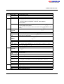
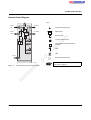
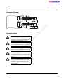
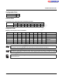
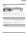
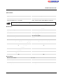
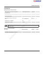
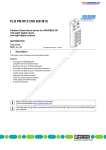
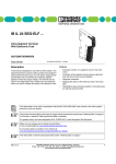
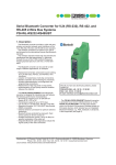
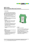
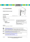
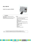
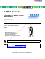
FLM BK PB M12 DI 8 M12
AUTOMATIONWORX
Data Sheet
–
–
om
in
ec
–
–
–
Connection to PROFIBUS-DP using M12 connectors
(B-encoded)
Opens the Fieldline modular local bus using M12
connectors (B-encoded)
Connection of digital sensors using M12 connectors
Flexible voltage supply concept
LED diagnostic and status indicators for
bus operation and voltage supply
Short-circuit and overload protection of the sensor
supply
IP65/IP67 protection
on
l
–
po
Features
–
Channel-specific diagnostics for different I/O devices
Dynamic configuration and empty spaces
ne
The device connects a Fieldline modular station to
PROFIBUS-DP and is also used to acquire digital signals.
–
–
nt
Description
s.
© PHOENIX CONTACT - 05/2005
co
m
Fieldline Modular Bus Coupler for PROFIBUS
With 8 Digital Inputs
7 0 0 8 A 0 0 1
Figure 1
FLM BK PB M12 DI 8 M12
This data sheet is only valid in association with the FLS FLM SYS INST UM E (Order No. 26 98 97 3) and
FLS FLM PB SYS PRO UM E (Order No. 26 99 07 9) user manuals.
Make sure you always use the latest documentation.
It can be downloaded at www.download.phoenixcontact.com.
A conversion table is available on the Internet at
www.download.phoenixcontact.com/general/7000_en_00.pdf.
7008_en_01
PHOENIX CONTACT GmbH & Co. KG • Flachsmarktstraße 8 • 32825 Blomberg • Germany
Phone: +49-(0) 5235-3-00 • Fax: +49-(0) 5235-3-4 12 00 • www.phoenixcontact.com
www.phoenixcontact.com/salesnetwork
1
FLM BK PB M12 DI 8 M12
Pin Assignment
U L
B U S
M D
R U N
B F
B U S IN
IN
x 1 0
0
O U T
4
6
8
0
2
x 1
U
4
9
O U T
L B O U T
2
1 2
1 0
B U S O U T
L B
8
6
U L S
2 M B D
L S
O U T
ULS OUT
IN 1 / IN 2
IN1 to IN8
I2
co
I1
IN 3 / IN 4
I4
I5
I6
I7
I8
In general, the maximum current load of 4 A
per contact must not be exceeded.
s.
I3
IN
U S
IN
U L S
po
L S
B K P B
om
7 0 0 8 A 0 0 2
Connections of the
FLM BK PB M12 DI 8 M12
on
l
in
ec
Figure 2
ne
IN 7 / IN 8
nt
IN 5 / IN 6
U
Meaning
Functional earth ground
PROFIBUS IN
PROFIBUS OUT
Local bus OUT (FLM local bus)
Power supply IN
(logic and sensor supply)
Voltage supply OUT (logic and sensor
supply) for additional devices
Inputs 1 to 8
m
F E
Des.
FE
BUS IN
BUS OUT
LB OUT
ULS IN
7008_en_01
PHOENIX CONTACT
2
FLM BK PB M12 DI 8 M12
Pin Assignment PROFIBUS
Local Bus Pin Assignment (LB OUT)
B U S IN
B U S O U T
L B O U T
L B O U T
6 6 2 5 B 0 0 4
m
LB OUT
DO
DO
DI
DI
GND
The thread is used for shielding.
on
l
in
ec
om
po
The shield is connected to FE in the device.
Pin
1
2
3
4
5
co
BUS OUT
VP
RxD/TxD-N (A)
DGND
RxD/TxD-P (B)
Shield
Local bus pin assignment (LB OUT)
s.
BUS IN
VP
RxD/TxD-N (A)
DGND
RxD/TxD-P (B)
Shield
Figure 4
nt
Pin
1
2
3
4
5
PROFIBUS pin assignment
(M12 B-encoded)
ne
Figure 3
7 0 0 8 A 0 0 5
7008_en_01
PHOENIX CONTACT
3
FLM BK PB M12 DI 8 M12
Pin Assignment of the Voltage Supply ULS
IN
Pin Assignment of the Inputs
O U T
6 9 5 4 A 0 0 3
m
Input Socket (INx/INx+1)
US +24 V
Input x+1
GND
Input x
FE
Assignment of the Input Sockets
po
You can change the transmission speed on the
local bus from 500 kBaud to 2 MBaud. The
transmission speed is switched to 2 Mbaud by
jumpering +24 V (UL, Pin 1) to Pin 5.
Pin
1
2
3
4
5
co
OUT
UL +24 V
US GND
UL GND
US +24 V
500 kbaud / 2 Mbaud
Pin assignment of the inputs
s.
IN
UL +24 V
US GND
UL GND
US +24 V
500 kbaud / 2 Mbaud
Figure 6
nt
Pin
1
2
3
4
5
Pin assignment of the voltage supply ULS
ne
Figure 5
6 6 2 5 A 0 0 6
1
5
om
4
2
3
on
l
IN x + 1
+ 2 4 V
IN x
in
ec
Voltages UL and US at female connector ULS
OUT can each only carry a maximum current of
2 A.
6 9 5 4 B 0 0 5
Figure 7
Assignment of the input sockets
Two input signals can be connected to each
input socket.
7008_en_01
PHOENIX CONTACT
4
FLM BK PB M12 DI 8 M12
Local Diagnostic and Status Indicators
Rotary Encoding Switches
U L
Set the station address using both rotary encoding switches
X10 (for the first digit of a two-digit number) and X1 (for the
second digit of a two-digit number). The PROFIBUS master
addresses the device by means of this station address.
M D
U L
M D
B F
IN
x 1 0
R U N
0
O U T
4
1 0
2
x 1
8
A new address value is only accepted upon
device power up.
2 M B D
4
9
The valid value range is between 1 and 126.
6
8
0
O U T
R U N
2
1 2
m
B F
L B
6
U L S
2 M B D
co
B U S
I2
I3
I4
I5
I6
I7
I8
s.
X X
I1
ne
po
X X
nt
X X
X X
U S
U S
U L S
B K P B
om
IN
Diagnostic and status indicators of the
FLM BK PB M12 DI 8 M12
on
l
Figure 8
in
ec
7 0 0 8 A 0 0 3
7008_en_01
PHOENIX CONTACT
5
FLM BK PB M12 DI 8 M12
Des.
UL
BF
Color
Green LED
ON:
OFF:
Red LED
LED OFF:
Meaning
Communications power
Communications power present.
Communications power too low.
No cyclic data transmission:
– PROFIBUS not connected, master not active
– Incorrect settings (configuration via master, station address)
Timeout expired
Device addressed by PROFIBUS;a parameterization was received
LED
green/red/
yellow
Green ON:
Device ready to operate
Green, flashing: A recoverable error is present (local bus not complete).
1 Hz
Station in process data mode.
Green/red
Device in selftest state.
Flashing
(flicker)
Red ON
An irrecoverable error is present.
Local bus is read, no process data transmission on local bus.
Red flashing:
1 Hz
Yellow flashing: More than 64 devices configured or system restriction of 244 bytes of process
1 Hz
data/configuration data exceeded.
OFF:
Voltage not present.
LED
Status of local bus communication
green/red/
yellow
Green ON
Local bus is running data cycles.
Green, flashing: I/O error present.
1 Hz
Red ON
Local bus stopped.
Red/yellow
There are differences between specified and current configuration.
Flashing: 1 Hz
Green/yellow
Preprogrammed error values are written to the outputs.
Flashing: 1 Hz
PLC stopped or PROFIBUS connection interrupted (cable, connector).
Yellow flashing: PCP error on a local bus device
1 Hz
OFF:
Voltage not present.
Green/red LED Voltage supply for inputs IN1 to IN8
Green ON:
Voltage supply present.
Red ON:
Overload or voltage supply too low.
OFF:
Voltage supply not present.
in
ec
on
l
RUN
om
po
ne
nt
s.
MD
co
m
No power supply for the device
(In this state the "UL" LED also is off because of the missing 24 V communications
power.)
Device status
US
7008_en_01
PHOENIX CONTACT
6
FLM BK PB M12 DI 8 M12
Internal Circuit Diagram
Key:
L B O U T
B U S
IN
Functional earth ground
B U S
O U T
P B
L B
U
L S
Optocoupler
O U T
µ C
Local bus/protocol unit
2 4 V
m
L B
5 V
Power supply unit with electrical
isolation
#
s.
2 4 V
Protocol chip
co
8
#
5 V
P B
nt
Input
#
L S
IN
om
po
U
ne
#
7 0 0 8 A 0 1 0
Internal wiring of the connection points
Electrically isolated area
For information on electrically isolated areas,
please refer to page 12.
on
l
in
ec
Figure 9
LED
7008_en_01
PHOENIX CONTACT
7
FLM BK PB M12 DI 8 M12
IN 3
6 9 5 4 A 0 0 8
Typical sensor connections
s.
Figure 10
m
IN 1
I4
co
+ 2 4 V
I3
IN 2
I2
IN 4
I1
+ 2 4 V
Connection Example
Meet noise immunity requirements
om
Ensure degree of protection
po
Connect FE using a mounting screw or a cable
connection to the FE connection latch (when
mounting on a non-conductive surface).
ne
nt
Connection Notes
To ensure IP65/IP67 protection, cover unused
sockets with protective caps.
in
ec
Avoid damage to the electronics
Make sure you only supply the sensors with the
voltage US provided at the connection points.
on
l
Avoid polarity reversal
Avoid polarity reversal of the supply voltages
UL and US in order to prevent damage to the
device.
Observe connection point assignment
When connecting the sensors, observe the
assignment of the connection points to the
PROFIBUS IN process data (see "Process
Data" on page 9).
7008_en_01
PHOENIX CONTACT
8
FLM BK PB M12 DI 8 M12
Configuration Data
ID number
07E9
Input address area
8 bits
Process Data
Assignment of the Connection Points to the IN Process Data
Device
Byte
Bit
Input
Byte 0
7
8
6
7
5
6
4
5
3
4
2
3
1
2
co
Diagnostic Data
Bit 4
Bit 3
X
X
X
X
X
X
X
X
X
X
X
X
X
X
X
X
X
X
X
X
0
1
0
1
0
1
po
0
0
Bit 2
0
1
Bit 1
nt
Bit 5
Bit 0
X
X
X
X
X
X
X
X
X
X
X
X
1
0
1
0
1
1
ne
Bit 6
Remark
Station status 1
Station status 2
Station status 3
Master address
diagnostics
High ID number
Low ID number
om
Byte 4
Byte 5
Bit 7
s.
Mapping of the Diagnostic Data in PROFIBUS
Diagnostic
Data
Byte 0
Byte 1
Byte 2
Byte 3
0
1
m
(Byte.bit) view
in
ec
Bytes 0 to 5 are PROFIBUS standard. Bytes 6 to 78 are device-specific. For information on device-specific
bytes, please refer to the FLS FLM PB SYS PRO UM E user manual, Order No. 26 99 07 9.
on
l
If a diagnostic event occurs the diagnostic data is always sent to the master by means of a diagnostic telegram
generated once by the device. The current status of the diagnostic data can be read by the device at any time.
For further information on the diagnostic data please refer to the FLS FLM PB SYS PRO UM E user manual,
Order No. 26 99 07 9.
7008_en_01
PHOENIX CONTACT
9
FLM BK PB M12 DI 8 M12
Technical Data
Device Dimensions
4 9 ,3 m m
( 1 . 9 4 1 '')
4 0 m m
( 1 . 5 7 5 '')
3 1 m m
( 1 . 2 2 0 '')
4
6
x 1
1 0
1 2
9
8
0
8
0
6
2
2
4
1 7 8 m m
( 7 . 0 0 8 '')
x 1 0
7 0 m m
( 2 . 7 5 6 '')
1 6 8 m m
( 6 . 6 1 4 '')
m
7 0 0 8 A 0 0 6
co
General Data
Order Designation
Order No.
Housing dimensions (width x height x depth)
Weight
Type of sensor connection
Permissible temperature (operation)
Permissible temperature (storage/transport)
Permissible humidity (storage/transport)
ne
nt
s.
FLM BK PB M12 DI 8 M12
27 36 33 0
70 mm x 178 mm x 49.3 mm
285 g, approximately
2, 3 or 4-wire technology
-25°C to +60°C
-25°C to +85°C
95%
om
po
For a short period, slight condensation may appear on the housing.
in
ec
Permissible air pressure (operation)
Permissible air pressure (storage/transport)
Degree of protection
Class of protection
on
l
Mechanical Requirements
Vibration test
Sinusoidal vibrations according to EN 60068-2-6
Shock test according to EN 60068-2-27
80 kPa to 106 kPa (up to 2,000 m above sea level)
70 kPa to 106 kPa (up to 3,000 m above sea level)
IP65/IP67 according to IEC 60529
Class 3 according to VDE 0106, IEC 60536
5g load in each space direction
30g load, half sinusoidal wave positive and negative in each
space direction
For additional information on mechanical requirements and ambient conditions, please contact
Phoenix Contact.
7008_en_01
PHOENIX CONTACT
10
FLM BK PB M12 DI 8 M12
Voltage Supply
Nominal value
Range
Current consumption at UL at 24 V DC
At 500 kbaud
At 2 Mbaud
Current consumption at US at 24 V DC
24 V DC
18 V DC to 30 V DC, ripple included
75 mA, typical (100 mA, maximum)
75 mA, typical (100 mA, maximum)
15 mA + sensor current, typical (600 mA, maximum)
m
Voltages UL and US at female connector ULS OUT can each only carry a maximum current of 2 A.
Digital Inputs
Number
Nominal input voltage
Range
Nominal input current
Current flow
Delay time
ne
nt
s.
co
8
24 V DC
-30 V DC < UIN < + 30 V DC
5 mA
Linear in the range 1 V < UIN < 30 V
tON = 2.9 ms, typical
tOFF = 2.6 ms, typical
< 30 m
on
l
in
ec
om
Input Characteristic Curve
Input Voltage (V)
-30 < UIN < 0.7
3
6
9
12
15
18
21
24
27
30
po
Permissible cable length to the sensor
Sensor Supply
Minimum sensor voltage
Nominal current per channel
Nominal current per device
Overload protection
Short-circuit protection
7008_en_01
Typical Input Current (mA)
0
0.5
1.0
1.5
2.2
3.0
3.6
4.4
5.1
5.8
6.6
US -1 V
600 mA
600 mA
Electronic per device
Electronic per device
PHOENIX CONTACT
11
FLM BK PB M12 DI 8 M12
Error Messages to the Higher-Level Control or Computer System
Sensor supply short-circuit
Yes
Sensor supply overload
Yes
If an error is triggered by an overload or short circuit of the sensor supply, the device switches off the sensor
supply of the channels and updates the diagnostics. The corresponding error message can then be read
out by the master. If the sensor supply US is not sufficiently high, the master can read out an appropriate
error message also.
Interface
Bus system
Incoming Bus
Coupling of shield connection
Transmission Speed
Outgoing Bus
Coupling of shield connection
Transmission Speed
co
Directly to FE
12 Mbaud, maximum
m
PROFIBUS DP
nt
s.
Directly to FE
12 Mbaud, maximum
po
Electrical Isolation/Isolation of the Voltage Areas
ne
For transmission rates of more than 3 MBaud in PROFIBUS, series inductance is available in the device.
Please observe the installation instructions of the PROFIBUS User Organization.
om
For device connection, please note the instructions and regulations in the "Installing the Fieldline Product
Range" user manual FLS FLM SYS INST UM E (Order No. 26 98 97 3).
on
l
in
ec
Separate Potentials in the FLM BK PB M12 DI 8 M12
- Test Distance
24 V supply (bus logic) / FE
24 V supply (bus logic) / digital inputs
(sensor supply/I/O)
24 V supply (bus logic)/incoming remote bus
Digital inputs (sensor supply/I/O) / FE
Digital inputs (sensor supply / I/O)/
incoming remote bus
Incoming remote bus / FE
7008_en_01
- Test Voltage
500 V AC, 50 Hz, 1 min
500 V AC, 50 Hz, 1 min
500 V AC, 50 Hz, 1 min
500 V AC, 50 Hz, 1 min
500 V AC, 50 Hz, 1 min
500 V AC, 50 Hz, 1 min
PHOENIX CONTACT
12
FLM BK PB M12 DI 8 M12
Ordering Data
Ordering Data Device and Accessories
Order Designation
FLM BK PB M12 DI 8 M12
Order No.
27 36 33 0
Pcs./Pkt.
1
IBS IP PROT-IO
PROT-M12-M
SACC-M12FSB-5SC SH
27 59 91 9
27 36 19 4
15 13 59 6
5
5
1
SACC-M12MSB-5SC SH
15 13 57 0
1
m
Description
Fieldline Modular Bus Coupler for PROFIBUS
With 8 Digital Inputs
Protective caps (for unused sockets)
Protective caps (for unused male connectors)
5-pos. shielded metal socket, B-encoded,
for the incoming local bus
Shielded metal connector, 5-pos., B-encoded,
for the outgoing remote bus and local bus
Markers
Bridging cable for power supply,
A-encoded, 5-pos., unshielded
Bridging cable for the local bus,
B-encoded, 5-pos., shielded
Assembly system for 5 devices
Assembly system for 7 devices
nt
s.
co
ZBF 12:UNBEDRUCKT
SAC-5P-MS/ 0,13-186/FS
SCO
SAC-5P-MSB/0,13-PUR/FSB
SCO SH
FLM MP 5
FLM MP 7
08 09 73 5
15 18 48 1
10
1
15 18 47 8
1
27 36 66 0
27 36 67 3
1
1
po
ne
Additional accessories for connecting the sensors and actuators can be found in the Phoenix Contact
PLUSCON catalog.
Ordering Data for Documentation
Order Designation
FLS FLM SYS INST UM E
FLS FLM PB SYS PRO UM E
Order No.
26 98 97 3
26 99 07 9
Pcs./Pkt.
1
1
on
l
in
ec
om
Description
"Installing the Fieldline Product Range" user manual
"Configuring a PROFIBUS DP System Using Devices
in the Fieldline Product Range" user manual
7008_en_01
PHOENIX CONTACT
13