1
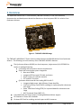
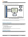
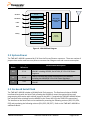
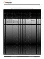
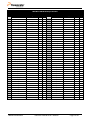
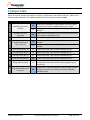
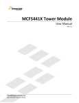
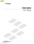
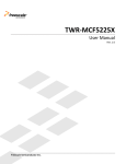
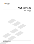
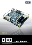
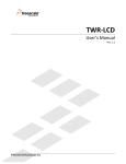
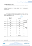
TWR-WIFI-AR4100 User’s Manual Rev. 1.1 Freescale Semiconductor Inc. TWRWIFIAR4100UM Contents 1 Overview ......................................................................................................................................................3 2 Reference Documents ..............................................................................................................................4 3 Hardware Features ...................................................................................................................................4 3.1 AR4100 Module ................................................................................................................................................................... 5 3.2 System Power ....................................................................................................................................................................... 6 3.3 On-board Serial Flash........................................................................................................................................................ 6 3.4 Debug UART Header .......................................................................................................................................................... 7 3.5 Elevator Connections ........................................................................................................................................................ 7 4 Jumper Table ........................................................................................................................................... 10 Revision History Revision 1.0 1.1 TWRWIFIAR4100UM Date Jun 2011 August 2011 Changes Initial Release Updated to reflect Qualcomm Atheros and WPS 2.0 support TWR-WIFI-AR4100 User’s Manual Page 2 of 10 1 Overview The Qualcomm Atheros Wi-Fi Tower Module (TWR-WIFI-AR4100) is a low-cost evaluation, demonstration and development board that features an ultra-low power 802.11n solution from Qualcomm Atheros. Figure 1 - TWR-WIFI-AR4100 Image The TWR-WIFI-AR4100 Wi-Fi Tower System module features the AR4100 solution from Qualcomm Atheros. The following is a brief summary of the TWR-WIFI-AR4100’s features: The Qualcomm Atheros AR4100, an ultra-low power, single stream (1x1) IEEE 802.11n System-in-package featuring: Low energy and Low system resource requirements Simple low cost wireless system integration Near zero RBOM Integrated RF front end, RF shield, and clocks Direct connect to a 50-ohm antenna FCC and Wi-Fi Certified Qualcomm Atheros world class leading 802.11n Wi-Fi: Integrated high-power, high efficiency Power Amplifier Low Density Parity Check (LDPC) encoding for improved uplink robustness over range Space Time Block Coding (STBC) for improved downlink robustness over range Wi-Fi Protected Setup (WPS 2.0) Compatible with the Tower System, including MQX based driver support SPI interface to Tower MCU modules On-board SPI Flash for enabling minimal impact to MCU resources TWRWIFIAR4100UM TWR-WIFI-AR4100 User’s Manual Page 3 of 10 A block diagram for the TWR-WIFI-AR4100 is shown in the figure below. TWR-ELEV (Primary Edge Connector) SPI, GPIO, IRQ On-board Antenna SPI GPIO Qualcomm Atheros AR4100 IRQ ultra-low power, single stream (1x1) IEEE 802.11n External Antenna Connector Serial Flash TWR-WIFI-AR4100 Figure 2 - TWR-WIFI-AR4100 Block Diagram The TWR-WIFI-AR4100 module connects to the Freescale Tower platform using the SPI interface and can be easily integrated using the TCP/IP stack of the Freescale MQX system. 2 Reference Documents The documents listed below should be referenced for more information on the Freescale Tower system and the TWR-WIFI-AR4100. Refer to http://www.freesale.com/tower for the latest revision of all Tower documentation. TWR-WIFI-AR4100 Quick Start Guide TWR-WIFI-AR4100 Lab Tutorial TWR-WIFI-AR4100 Schematics For technical documents specific to the Qualcomm Atheros Wi-Fi module refer to http://www.qca.qualcomm.com/ 3 Hardware Features This section provides more details about the features and functionality of the TWR-WIFI-AR4100. TWRWIFIAR4100UM TWR-WIFI-AR4100 User’s Manual Page 4 of 10 Figure 3 - Callout Diagram for TWR-WIFI-AR4100 3.1 AR4100 Module The AR4100 is a small form-factor, single stream, 802.11 b/g/n Wi-Fi “System-in-Package” (SIP) solution. The AR4100 has been developed to support applications hosted by low-resource microcontrollers that send infrequent data packets over the network. Typically, these 802.11 applications will place a higher priority on system cost, power consumption, ease of use, and fast wake-up times as compared to high throughput. The AR4100 integrates all Wi-Fi functionality into a low-profile, 8.3mm x 9.2mm LGA package that can be easily mounted via low-cost PCB manufacturing flows. The device requires only a few external bypass capacitors and a connection to an antenna for a board level design. As an added cost reduction and convenience, the SIP module is pre-certified with the FCC and other major regulatory bodies. The AR4100 employs the world's lowest power consumption embedded architecture. It has been optimized for client applications in the home and enterprise that have lower data rates, and transmit or receive data on an infrequent basis. The AR4100 features standby current consumption as low as 5uA. Additional optimizations, including a reduced host driver footprint, allow easy integration with low-cost microcontrollers. The AR4100 also includes Qualcomm Atheros’ industry leading high-efficiency, high-output EPA™ power amplifier with zero calibration and integrated LNAs. RF matching circuits, a reference crystal, and a T/R switch are also integrated, eliminating the need for an external RF components and thus enabling direct antenna connection. The end result is a device that is the best-in-class for ease of system design. TWRWIFIAR4100UM TWR-WIFI-AR4100 User’s Manual Page 5 of 10 SPI Master NVRAM I/F UART Debug Ports GPIO I/O Management Battery Power Management 32kHz Sleep Clock 802.11b/g/n Baseband, MAC, & Radio EPA, Balun, T/R Switch Host I/F AHB Internal Bus SPI Slave System Controller System Clock Figure 4 - AR4100 Block Diagram 3.2 System Power The TWR-WIFI-AR4100 is powered by 3.3V from the Primary Elevator connector. There are number of jumpers that can be used to as test points to measure the voltage as well and current consumption. Jumper Name Voltage Reference J23 3.3 V J1 3.3 V J2 1.8V Measurement Description Used to measure the power consumption of the entire TWR-WIFIAR4100: including AR4100, Serial Flash, & 3.3V->1.8V Power Regulator Used to measure the power consumption of the AR4100: including the AR4100 & 3.3V->1.8V Power Regulator Used to measure the Power consumption of the 1.8V rail of the AR4100 3.3 On-board Serial Flash The TWR-WIFI-AR4100 includes a 16-Mbit Serial Flash memory. The Qualcomm Atheros AR4100 interfaces directly with the Serial Flash, allowing the AR4100 to access the required drivers and programming information with minimal impact to the MCU. If required the TWR-WIFI-AR4100 allows the interface to be switched from the AR4100 to the Tower MCU (via the TWR-ELEV connections). The interface to the Serial Flash can be switched by removing the following resistors (R32, R33, R34, R35) and populating the following resistors (R24, R25, R26, R27). Refer to the TWR-WIFI-AR4100 for additional details. TWRWIFIAR4100UM TWR-WIFI-AR4100 User’s Manual Page 6 of 10 3.4 Debug UART Header For advanced debug purposes, the TWR-WIFI-AR4100 provides access to a UART signals on J10. The following signals are accessible. 3.3V J10 2 1 4 3 6 5 8 7 10 9 12 11 J22 Debug UART RX R38 Debug UART TX R37 SPI Flash CS Figure 5 - Debug UART Header The Debug UART RX signal is not configured as a UART signal by the AR4100 firmware. Prior to firmware reconfiguring this pin, DEBUG_UART_RX must not be connected to any external stimulus. Jumper J22 is provided to isolate DEBUG_UART_RX from J10. This allows the required debug hardware (UART transceiver) to remain connected to J10, requiring the user to only remove the J22 shunt when the part is reset. 3.5 Elevator Connections The TWR-WIFI-AR4100 features two expansion card-edge connectors that interface to Elevator boards in a Tower system: the Primary and Secondary Elevator connectors. The Primary Elevator connector, comprised of sides A and B, is utilized by the TWR-WIFI-AR4100, while the Secondary Elevator connector only makes connections to ground (GND). Table 1 provides the pinout for the Primary Elevator Connector. An “X” in the “Used” column indicates that there is a connection from the TWRWIFI-AR4100 to that pin on the Elevator connector. An “X” in the “Jmp” column indicates that a jumper is available that can configure or isolate the connection from the Elevator connector. TWRWIFIAR4100UM TWR-WIFI-AR4100 User’s Manual Page 7 of 10 Table 1. TWR-WIFI-AR4100 Primary Elevator Connector Pin-out TWR-WIFI-AR4100 Primary Connector Side B Pin # Name B1 5V B2 B3 B4 ELE_PS_SENSE B5 GND B6 B7 GND SPI1_CLK / SDHC1_CLK B8 SPI1_CS1 / SDHC1_CS1 B9 SPI1_CS0 / SDHC1_CS0 B10 B11 Side A Usage Used 5.0V Power X GND Ground X 3.3V 3.3V Power X Jmp X Elevator Power Sense Pin # Name A1 5V A2 A3 Ground X 3.3V 3.3V Power X X A4 3.3V 3.3V Power X X Ground X A5 GND Ground X Ground Serial Flash SPI_CLK X A6 Ground X X A7 GND SCL0 A8 SDA0 GPIO9 / CTS1 AR4100 GPIO2 X Ground X Ground X 3.3V Power X A9 SPI1_MOSI / SDHC1_CMD Serial Flash SPI_MOSI X A10 SPI1_MISO / SDHC1_D0 Serial Flash SPI_MISO X A11 Mechanical Key GPIO8 / SDHC_D2 ETH_COL A12 ETH_CRS B13 ETH_RXER A13 ETH_MDC B14 ETH_TXCLK A14 ETH_MDIO B15 ETH_TXEN A15 ETH_RXCLK B16 ETH_TXER A16 ETH_RXDV B17 ETH_TXD3 A17 ETH_RXD3 B18 ETH_TXD2 A18 ETH_RXD2 B19 ETH_TXD1 A19 ETH_RXD1 B20 ETH_TXD0 A20 ETH_RXD0 A21 SSI_MCLK A22 SSI_BCLK B22 GPIO2 B23 GPIO3 AR4100 GPIO0 X AR4100 CHIP PWD X X A23 SSI_FS A24 SSI_RXD A25 SSI_TXD A26 B24 CLKIN0 B25 CLKOUT1 B26 B27 GND AN7 A27 GND AN3 B28 AN6 A28 AN2 B29 AN5 A29 AN1 B30 AN4 A30 AN0 B31 GND DAC1 A31 B32 A32 GND DAC0 B33 TMR3 A33 TMR1 B34 TMR2 A34 TMR0 B35 GPIO4 A35 GPIO6 B36 3.3V PWM7 A36 B37 A37 3.3V PWM3 B38 PWM6 A38 PWM2 B39 PWM5 A39 PWM1 B40 PWM4 A40 PWM0 B41 CANRX A41 RXD0 TWRWIFIAR4100UM Ground Ground 3.3V Power X X X X X GPIO7 / SD_WP_DET B12 X Jmp GND X GPIO1 Used X Serial Flash SPI_CS ipB21 Usage 5.0V Power TWR-WIFI-AR4100 User’s Manual Page 8 of 10 X TWR-WIFI-AR4100 Primary Connector Side B Side A Pin # Name Pin # Name B42 CANTX Usage Used Jmp A42 TXD0 B43 1WIRE A43 RXD1 B44 SPI0_MISO AR4100 SPI_MISO X A44 TXD1 B45 SPI0_MOSI AR4100 SPI_MISO X A45 GPIO B46 SPI0_CS0 AR4100 SPI_CS X A46 GPIO B47 SPI0_CS1 A47 GPIO B48 SPI0_CLK B49 B50 GND SCL1 B51 SDA1 B52 AR4100 SPI_CLK X A48 GPIO Ground X A49 GND A50 GPIO A51 GPIO GPIO5 A52 GPIO B53 USB_DP_PDOWN A53 B54 A54 GPIO USB_DM B55 USB_DM_PDOWN IRQ_H A55 USB_DP B56 IRQ_G A56 USB_ID A57 USB_VBUS A58 TMR7 A59 TMR6 A60 TMR5 B57 IRQ_F B58 IRQ_E B59 IRQ_D B60 IRQ_C B61 IRQ_B B62 IRQ_A B63 FB_ALE/FB_CS1_b B64 FB_CS0_b B65 GND B66 B67 AR4100 SPI_INT X X AR4100 SPI_INT X X AR4100 SPI_INT X X Usage Used Ground X AR4100 CHIP PWD X Ground X A61 TMR4 A62 RSTIN_b A63 RSTOUT_b A64 CLKOUT0 A65 GND FB_AD15 A66 FB_AD14 FB_AD16 A67 FB_AD13 B68 FB_AD17 A68 FB_AD12 B69 FB_AD18 FB_AD19 A69 FB_AD11 B70 A70 FB_AD10 B71 FB_R/W_b A71 FB_AD9 B72 FB_OE_b A72 FB_AD8 B73 FB_D7 A73 FB_AD7 B74 FB_D6 A74 FB_AD6 B75 FB_D5 A75 FB_AD5 B76 FB_D4 A76 FB_AD4 B77 FB_D3 A77 FB_AD3 B78 FB_D2 A78 FB_AD2 B79 FB_D1 A79 FB_AD1 B80 FB_D0 A80 FB_AD0 B81 GND Ground X A81 GND Ground X B82 3.3V 3.3V Power X A82 3.3V 3.3V Power X TWRWIFIAR4100UM AR4100 SPI_INT Ground X X X X TWR-WIFI-AR4100 User’s Manual Page 9 of 10 Jmp X X 4 Jumper Table There are several jumpers provided for isolation, configuration, and feature selection. Refer to the following table for details. The default installed jumper settings are shown in bold. 1-2 J2 2-3 AR4100 1.8V Power Regulation 1-2 J11 AR4100 Power Source Selection Setting AR4100 Power Down 1-2 J12 J1 Option AR4100 Reset/Power Down Selection 1-2 Power down the AR4100 J16 J15 J14 J13 Interrupt Select (IRQ_G) 1-2 Tower System IRQ_G will connect to AR4100 SPI_INT Interrupt Select (IRQ_E) 1-2 Tower System IRQ_E will connect to AR4100 SPI_INT Interrupt Select (IRQ_C) 1-2 Tower System IRQ_C will connect to AR4100 SPI_INT Interrupt Select (IRQ_A) 1-2 Tower System IRQ_A will connect to AR4100 SPI_INT J22 Tower System RSTOUT_b will control reset / power down of AR4100 Tower System GPIO3 will control reset / power down of AR4100 Debug UART RX Enable 1-2 J23 2-3 Description Supply 3.3V to AR4100 via Tower Elevator (J1 can be used as a measurement point for AR4100 specific power usage) Not Used (On-board power regulation is not implemented by default) Supply 1.8V to the AR4100 (J2 can be used as a measurement point specific to the AR4100 1.8V) TWR-WIFI-AR4100 Power Connection 1-2 TWRWIFIAR4100UM Connects Debug UART RX from AR4100 to J10. This jumper should not be connected until after SW reconfigures signals as UART RX. Supply 3.3V to TWR-WIFI-AR4100 via Tower Elevator (J23 can be used as a measurement point for the entire TWR-WIFIAR4100 module) TWR-WIFI-AR4100 User’s Manual Page 10 of 10