1
User’
User’s Manual
LG Programmable Logic Controller
FieldBus
Module
MASTER-K
Link
K7F-FUEA
K4F-FUEA
K3F-FUEA
LG Industrial Systems
Contents
Chapter 1 Introduction.................................................................. 1-1
Chapter 2 Terms and concepts of communication
2.1
2.2
Description of terms ................................................................................... 2-1
Concept of Fnet communication ................................................................ 2-4
2.2.1
How to generate and move LAS ................................................................................... 2-4
2.2.2
How to assign token .....................................................................................................2-4
Chapter 3 General specifications
3.1
3.2
General specifications of communication module(Fnet) ......................... 3-1
Structure and configuration ........................................................................ 3-2
3.2.1
Fnet master module structure : K7F-FUEA, K7F-FUOA, K4F-FUEA, K3F-FUEA ....... 3-2
3.2.2
Fnet slave module structure : K7F-RBEA, K7F-RBOA, K4F-RBEA ............................. 3-4
3.2.3
3.2.4
Fnet Computer interface module structure : G0L-FUEA ............................................... 3-6
Fnet LED signal name and indication content .............................................................. 3-7
3.2.5
3.2.6
Fnet station number setting .......................................................................................... 3-7
Fnet mode setting ......................................................................................................... 3-8
Chapter 4 Transmission specifications
4.1
Transmission specifications of Fnet .......................................................... 4-1
4.1.1
Transmission specifications of Fnet Master module...................................................... 4-1
4.1.2
4.1.3
Transmission specifications of Fnet Slave module ....................................................... 4-2
Transmission specifications of Fnet Option module ..................................................... 4-2
4.2
4.2.1
4.2.2
4.3
Cable specifications .................................................................................... 4-5
Twisted pair cable for Fnet ........................................................................................... 4-5
Optical cable for Fnet .................................................................................................... 4-6
How to connect communication cable ...................................................... 4-8
4.3.1
Electric(twisted pair) cable connection .......................................................................... 4-8
4.3.2
Electric(twisted pair) cable connector connection ........................................................ 4-8
4.3.3
Optical cable connection ............................................................................................... 4-9
4.4
4.4.1
Terminal resistance ..................................................................................... 4-9
Electric network terminal resistance of Fnet ................................................................. 4-9
Contents
Chapter 5 System configuration
5.1
5.2
MASTER-K PLC network system ................................................................5-1
Fnet network system ...................................................................................5-2
5.2.1
Configuration of Fnet master system (electric network) ............................................... 5-2
5.2.2
5.2.3
Configuration of Fnet master system (optical network) ................................................ 5-2
Configuration of Fnet master system (network combined with electric/optical module) 5-3
5.2.4
Configuration of Fnet slave system (electric network) .................................................. 5-4
5.2.5
5.2.6
Configuration of Fnet slave system (optical network) ................................................... 5-5
Configuration of Fnet slave system (electric/optical network) ...................................... 5-6
5.2.7
Configuration of Fnet combined system (electric/optical network)
............................ 5-7
Chapter 6 Communication program
6.1
6.2
Programming method ..................................................................................6-1
High speed link ...............................................................................................6-2
6.2.1
Introduction ................................................................................................................... 6-2
6.2.2
6.2.3
6.2.4
Procedure of high speed link parameter setting............................................................ 6-3
High speed link parameter setting ................................................................................. 6-4
Operation procedure by .......................................................................... 6-8
6.2.5
Information of ......................................................................................... 6-9
6.2.6
6.2.7
6.2.8
Speed calculation of high speed link ........................................................................... 6-14
Ex. 1 : among PLCs of Fnet ................................................................ 6-17
Ex. 2 : of master + remote I/O stations in Fnet ................................... 6-20
6.3
Communication instructions ....................................................................6-25
6.3.1
Introduction .................................................................................................................. 6-25
6.3.2
Programming procedure .............................................................................................. 6-25
6.3.3
Types of communication instructions ......................................................................... 6-25
READ........................................................................................................................... 6-26
WRITE ......................................................................................................................... 6-27
STATUS....................................................................................................................... 6-27
RGET ........................................................................................................................... 6-28
RPUT ........................................................................................................................... 6-29
6.3.4
The input condition of communication instructions...................................................... 6-29
6.3.5
Example of Read / Write instructions .......................................................................... 6-30
6.4
KGLWIN remote connection service ........................................................6-34
6.4.1
Introduction ................................................................................................................. 6-34
6.4.2
6.4.3
KGLWIN remote connection ....................................................................................... 6-35
Remote module information ....................................................................................... 6-38
Contents
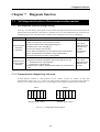
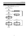
Chapter 7 Diagnosis function
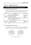
7.1
Self diagnosis function of Fnet communication module .......................... 7-1
7.1.1
Self diagnosis function during running .......................................................................... 7-1
7.1.2
Communication diagnosis by test mode ....................................................................... 7-1
Chapter 8 Installation and testing operation
8.1
Installation and testing operation of Fnet communication module ......... 8-1
8.1.1
8.1.2
Installation of Fnet master module ................................................................................ 8-1
Installation of Fnet slave module .................................................................................. 8-2
8.1.3
Installation procedure of Fnet module .......................................................................... 8-3
8.1.4
8.1.5
Cautions on installation of Fnet module ....................................................................... 8-4
Preparations during testing operation of Fnet module .................................................. 8-6
8.1.6
Testing operation procedure of Fnet module ................................................................ 8-7
8.2
Installation and testing operation of Fnet option unit .............................. 8-9
8.2.1
Active coupler of Fnet .................................................................................................... 8-9
8.2.2
E/O converter(Electric/optical signal converter) ......................................................... 8-10
8.2.3
Repeater(Electric signal restructure) .......................................................................... 8-11
8.3
Repair and check ...................................................................................... 8-16
8.3.1
Daily check .................................................................................................................. 8-16
8.3.2
Regular check ............................................................................................................. 8-17
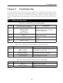
Chapter 9 Troubleshooting
9.1
9.2
Abnormal operations .................................................................................. 9-1
Troubleshooting by each error code ......................................................... 9-3
9.2.1
Error code E00-01 : Hardware error ............................................................................. 9-3
Error code E00-03 : Hardware error of option module .................................................. 9-3
9.2.2
9.2.3
Error code E00-02 : Interface error ............................................................................... 9-4
Error code E00-04 : I/O initialization error of FSM(Fieldbus Slave Module) ................. 9-5
9.2.4
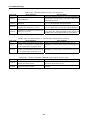
Error code E01-01 : Communication failure in Fnet ..................................................... 9-6
9.2.5
Error code E01-03 : Communication failure in FOU group ........................................... 9-6
Error code E02-01 : PLC interface error during operation ............................................ 9-7
9.2.6
9.2.7
Error code E02-02 : Slave mounting and writing interface error during operation ....... 9-8
Error code E03-01 : parameter error ..................................................... 9-9
Contents
9.2.8
Error code E03-02 : not run ................................................................ 9-10
9.2.9
Error code E03-03 : RUN link contact of not ON ................................. 9-11
9.2.10 Error code E03-04 : Trouble contact of ON ......................................... 9-12
9.2.11 Error code E04-01 : Execution error of Fnet communication command .................... 9-13
Error code E04-02 : Execution error of Mnet communication command .................... 9-13
9.2.12 Error code E05-01 : Time out error in KGLWIN communication ................................. 9-14
9.2.13 Error code E05-02 : Internal error in the Fnet/Mnet KGLWIN communication ........... 9-15
Appendix
A1.
LED specifications ...................................................................................... A-1
A1.1
LED specification of Fnet master module .....................................................................A-1
A1.2
A1.3
LED specification of slave module ................................................................................A-4
LED specification of stand-alone type remote module(G0L-SMQA/SMIA/SMHA) ......A-7
A1.4
LED specification of repeater module(G0L-FREA) ......................................................A-7
A1.5
A1.6
LED specification of electric and optical signal switching module(G0L-FOEA) ...........A-7
LED specification of active coupler module(Optical signal distributor) .........................A-7
A1.7
LED specifications of Mnet communication module .....................................................A-8
A2.
A3.
Communication module setting in the Fnet/Mnet PC ............................. A-10
STATUS code value and description for communication instructions.. A-11
A3.1
Errors received from communication module .............................................................A-11
A3.2
STATUS values indicated in CPU ..............................................................................A-12
A4.
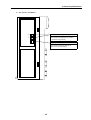
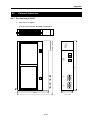
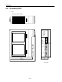
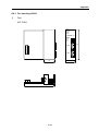
Outward dimension .................................................................................. A-13
A4.1
A4.2
For mounting GM1/2/3 ................................................................................................A-13
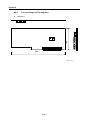
For mounting GM4 ......................................................................................................A-15
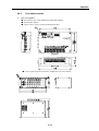
A4.3
A4.4
For mounting on GM6 .................................................................................................A-16
For mounting on PC(Computer) .................................................................................A-17
A4.5
Fnet option module .....................................................................................................A-18
1. Introduction
! "#
!
$%
MASTER-K Fnet
&'
() !'*'$
+),"
)
!(& !,(!)( !!"
)) - ) . ) )
-).,)!)&!& )(& !,")&)!!))()*&(
&)(! ,"
Remark
1. MASTER-K Fnet is abbreviated as Fnet for simplicity of description.
2. Program in this User’s Manual has been prepared on the basis of KGLWIN V1.3.
1-1
1. Introduction
,,
$/"/,"! ,"
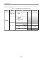
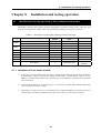
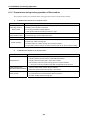
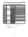
Table 1.1
Network
Module
Master module
(FMM)
Type of MASTER-K PLC communication module
Type of
connection cable
Twisted pair
(electric)
Name of
communication module
Interface
Optical
MASTER-K
Fnet
Slave module
(FSM)
Twisted pair
(electric)
Remote I/O
Optical
Option module
Mounting base
G0L-FUEA
Computer
K7F-FUEA
K1000S
K4F-FUEA
K300S
K3F-FUEA
K200S
K7F-FUOA
K1000S
K7F-RBEA
K1000S
K4F-RBEA
K300S
G0L-SMQA
Single
G0L-SMIA
Single
G0L-SMHA
Single
K7F-RBOA
K1000S
Twisted pair
Repeater
G0L-FREA
Single
Optical/Twisted pair
Optical/electr
ic converter
G0L-FOEA
Single
Optical
Active
coupler
G0L-FACA
G0L-FAPA
G0L-FABA
Single
Cable
Cable
G0C-T
Twisted pair cable
G0C-F
Optical fiber cable
1-2
2. Terms and Concepts of communication
2.1
Description of terms
Master module(Fnet Master Module ; FMM)
$!!!!'*0)!"
Slave module(Fnet Slave Module; FSM)
$!!!!!)!"
Option module(Fnet Option Module)
$ !! ! , &( 1 !! ( ,!),"
Local station
2
3'# ( !(,),!
!,"
Remote station
)))(!!
Remote I/O station
')*)!!!! !
'*0!!! &,'*0!!"
Fnet
$,&!&()
) !& 0'" ) 45-/
)(.(4/-6/"56)(.()( ("( )
()) ) ))(
"
2-1
2. Terms and Concepts of communication
Token
,!,,,,) !!"
SAP(Service Access Point)
! & !!( ))
)) ,"&(
7 8( " -9: 8( .
Fnet station number
!!!!-;$$("""".),$)"
! $ !! !( !&,
& !!
"
Active coupler
!,)!),()
( , !) ) !! ,
"
Repeater
1 !! ( 1 !!,!)!!,"
E.O.C(Electric/Optical Converter)
! & ) !! , !! ,( !! , ) !! ,( , !),"
2-2
2. Terms and Concepts of communication
Manchester Biphase-L
8 ! ! $" 8 ! , (
& &"
CRC(Cyclic Redundancy Check)
!( ! ! < +,!( !"
Terminal resistance
= ! !) !, ) &, ) ) ( !$//>(/*53!
;?(/*@3"
High speed link
!,
!!! (!&
,)(1!! ,
)!2
3'#"
KGLWIN(Programming and debugging tool)
),! !((()(,
!"
FAM(FA Manager)
), )) & !( & )( 1 ( ,*, &( *)),! !,$!!)"
Segment
, ! ( , ,
&-2 (0()."
Network
!! !(, ,!!(!"
2-3
2. Terms and Concepts of communication
2.2
Concept of Fnet communication
!$!!! -&."0
$
!!!($
!!!"
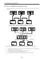
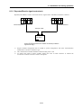
2.2.1 How to generate and move LAS
!,!!!(,,%
/.
!,($
!!!)
"
5.
3 ) ! ! ! !, ( !!!!"
6.
')!,!!!(!!!
!!,$
("
@.
0 1,"
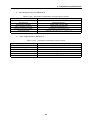
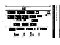
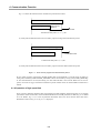
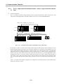
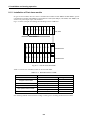
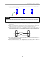
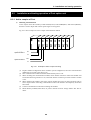
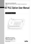
2.2.2 How to assign token(Suppose that the Station FMM_01 is LAS)
FMM_01(LAS)
FMM_02
FMM_03
FMM_04
FMM_05
Token
transmission
of station
FMM_02
Circulated
Token
Passing
Return of token
Token
transmission of
station FSM_03
Return of
token
Token
transmission of
station FSM_04
Return of
token
Return of token
Token
transmission of
station FSM_05
Data
transmission
of LAS’s own
station
Use within
8ms
Token transmission of
FMM_01 (LAS station
also transmits its own
FMM 01)
Return of
token
Data transmission
of self station
Use within 8ms
Data transmission of
self station
Use within 8ms
2-4
Data transmission of
self station
Use within 8ms
Data transmission of
self station
Use within 8ms
A Token return in each
station is performed to
present LAS station.
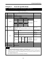
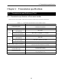
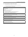
3. General specifications
3.1
General specifications of communication module(Fnet)
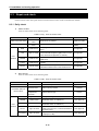
2)
%
6"/2)
No.
Item
1
Operating temp.
0+55
Spec.
2
Storage temp.
-25+70
3
Operating moist.
5~95% RH, non-condensing
4
Storage moist.
5~95% RH, non-condensing
Related spec.
For discontinuous vibration
5
Vibration
Frequency
Acceleration
Amplitude
10f57Hz
-
0.075mm
57f150Hz
Impact
Frequency
Acceleration
Amplitude
10f57Hz
-
0.035mm
Ambient conditions
9
Height
10
Pollution level
11
Cooling type
-
Test spec. reference
within LG Industrial
Systems
Static electric
discharging
Voltage : 4kV(Contact discharging)
IEC 1131-2,
IEC 801-2
Radiation
electric field
noise
27500 MHz, 10V/m
IEC 1131-2,
IEC 801-3
Fast
transient/burst
noise
8
1,500V
Impulse noise
Noise
4.9
ICE 1131-2
Each 10 times in
X,Y,Z directions
• Max. impact acceleration:147 (15G)
• Authorized time : 11ms
IEC 1131-2
• Pulse wave : Sign half-wave pulse(each 3 times in X,Y,Z
directions)
Square wave
7
-
For continuous vibration
57f150Hz
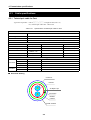
6
9.8
Number
Segment
Power
module
Digital
input/
output
(24V or
more)
Voltage
2kV
1kV
Digital input/output
(less than
24V)Analog
input/output
communication
interface
0.25 kV
IEC 1131-2,
IEC 801-4
No corrosive gas and dust
Up to 2,000m
2 or less
Natural air cooling
Remark
1.
2.
IEC(International Electro-technical Commission) : International non-governmental association, which
establishes international standards in the field of electric and electronics.
Pollution level : This is an indication showing pollution of surrounding environment, which determines
insulation performance of device, and generally the pollution level 2 means the conditions in which only
non-conductive pollution occurs.
But, temporary conduction may occur according to condensing.
3-1
3. General specifications
3.2
Structure and configuration
,)& )$
!"
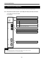
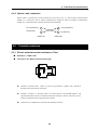
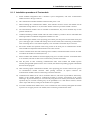
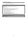
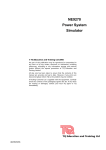
3.2.1 Fnet master module structure : K7F-FUEA, K7F-FUOA, K4F-FUEA, K3F-FUEA
1) K7F-FUEA, K7F-FUOA, K4F-FUEA
Type name indicating section
Indicates type name of communication module
LED indicating section
RUN
Indicates the status of CPU module and interface
LAS
Indicates that communication module is performing LAS function.
TOKEN
Indicates whether communication module is transmitting/ receiving
or not.
FAULT
Flickers when the error that normal operation is not possible
occurred in communication module
Indicates whether communication module has a token or not.
Tx/Rx
Station number setting switch
Sets station number in the range of 0~63 station(Use decimal).
Mode setting switch
Sets operation mode of communication module
Communication connector
Connector for electric cable connection to connect communication module.
Remark
1.
2.
In the figure shown above, connector of K7F-FUOA is made of optical connector.
For mode setting switch, see 3.2.6 Fnet mode setting.
3-2
3. General specifications
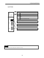
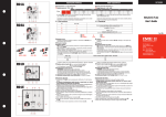
2) K3F-FUEA
LED indicating section
RUN
Indicates the status of CPU module and interface
LAS
Indicates that communication module is performing LAS function.
TOKEN
Indicates whether communication module has a token or not.
Tx/Rx
Indicates whether communication module is transmitting/ receiving
or not.
FAULT
Flickers when the error that normal operation is not possible
occurred in communication module
Type name indicating section
Indicates type name of communication module
Mode setting switch
Sets operation mode of communication module
Communication connector
Connector for electric cable connection to connect communication module.
Remark
1.
The station number setting switch is placed in the case.
3-3
3. General specifications
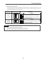
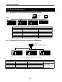
3.2.2 Fnet slave module structure : K7F-RBEA, K7F-RBOA, K4F-RBEA
K7F-RBEA
Type name indicating section
Indicates type name of communication module
LED indicating section
RUN $%
Indicates the status of communication module
"#
TOKEN
Indicates whether communication module has a token
&'()#
*+,-./
or not.
&010 2./
Tx/Rx
DE?@FG
Indicates whether communication module is
34"5&
transmitting/receiving or not.
Y
6789:;<=>?@ABC1'DE
34"5&
?@FG
FAULT Flickers when the communication error occurred.
SYS
Flickers when serious error of system itself or I/O module
FAULT
error occurred
!
Station number setting switch
Sets station number in the range of 0~63 station(Set in decimal).
HIJ
Mode setting switch
Sets operation mode of communication module
Communication connector (RS-232C)
Cable connector of KGLWIN connection.
Z[\C#STUQRVWX
Communication connector
Connector for electric cable connection to connect communication
KLMNO<POQRSTUVWX
module.
Remark
In the figure shown above, connector of K7F-RBOA is made of optical connector, and there is no RS-232C port
in K4F-RBEA.
3-4
3. General specifications
Station number setting switch
8
Sets master station number of remote
communication module(Set in the range of
0~63 station using decimal).
8
Output of emergency data
!"#$%
Specifies output data type when
&'()*+,-
communication failure by cable cut off.
./.01234567
(See 3.2.6 Fnet mode setting)
3-5
3. General specifications
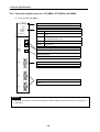
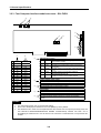
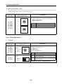
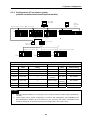
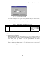
3.2.3 Fnet Computer interface module structure : G0L-FUEA
B/ B/>
+opqrrpstt
Port
selection
0
1
2
3
4
5
6
7
Address
selection
3E0
FC00
3C0
F800
F400
F000
EC00
3A0
340
2E0
380
360
320
300
DC00
D800
2A0
D400
280
D000
CC00
C800
E
220
F
200
9
A
B
C
D
260
240
No.2
Indicates the status of CPU module and interface
+),-./0123456
j ()*RUN
No.3
LAS
Indicates that communication module is performing
j 78 9:,-78;<%=>?@56"
LAS function.
No.4
TOKEN
Indicates whether communication module has token
9:,-DEFGH56
j ABC*
or not.
9:,-K%:GH56
j AIJ(I
No.5
Tx/Rx
Indicates whether communication module is
transmitting/receiving or not.
j )7A 9:,-L!3MN&;OP%QRLSTU6VW
No.6
FAULT
Flickers when the error that normal operation is not
possible occurred in communication module
E800
E400
E000
2C0
8
Station number setting switch
!"#$%& !'
Sets station number in the range of 0~63 station(Set in decimal).
Mode setting switch
9:,-OX,Y
!
Sets operation mode of communication
module
C400
C000
LED indicating section
No.1 POWER Indicates whether power is being supplied to
j +Bk( 9:,-L^lmnGH56
communication module
Reset switch
A switch to initialize communication module
9:,-@f;g6h;]2i
Communication connector
Connector for electric cable connection to connect communication
module.
9:,-@Z[\;]^;_`abcde0
Remark
1.
2.
3.
For mode setting switch, see 3.2.6 Fnet mode setting.
Port is set to No.5(340) and address is set to No.9(D800) by factory default.
This should be set in order not to be duplicated with other device area of computer previously used, and
add DEVICE=C:\WINDOWS\EMM386.EXE NOEMS X=D800-D8FF(if address has been set to
No.9(D800)) in CONFIG.SYS to use set area for not continuous or extended area of computer but this
module.
3-6
3. General specifications
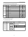
3.2.4 Fnet LED signal name and indication content
Device
type
K7F-FUEA
K7F-FUOA
K4F-FUEA
K3F-FUEA
GOL-FUEA
K7F-RBEA
K7F-RBOA
K4F-RBEA
G0L-SMQA
G0L-SMIA
G0L-SMHA
LED
Name
Meaning of LED indication
LED On
LED Off
Normal
Abnormal
RUN
Indicates the status of CPU module and interface
LAS
Indicates that communication module is performing LAS
In proceeding
function.
Does not
have
TOKEN
Indicates whether communication module has token or not.
Has
Tx/Rx
Indicates whether communication module is transmitting/
receiving or not.
FAULT
Indicates the status of communication module.
Abnormal
Normal
RUN
Indicates the status of communication module.
Normal
Abnormal
Has
Does not
have
Flicker during
communication
TOKEN
Indicates whether communication module has token or not.
Tx/Rx
Indicates whether communication module is transmitting/
receiving or not.
FAULT
Indicates whether communication error exists or not.
Abnormal
Normal
SYS
FAULT
Indicates whether system error or I/O module error occurred
or not.
Abnormal
Normal
Indicates power status.
Power On
Power Off
PWR
TRX
Indicates Tx/Rx or not of communication module.
ERR
Indicates communication error or not.
Flicker during
communication
Flicker during
communication
Abnormal
Normal
* For details on LED, see Appendix A1, LED indication.
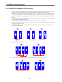
3.2.5 Fnet station number setting
!"#
Applied
Device type
K7F-FUEA
K7F-FUOA
K7F-RBEA
K7F-RBOA
K4F-FUEA
K4F-RBEA
K3F-FUEA
G0L-FUEA
G0L-SMQA
G0L-SMIA
G0L-SMHA
Detailed drawing of
station number switch
Description
(1) Station number can be set from 0 to 63(Decimal).
(2) Station number setting
(Factory default is 0)
Switch
Setting
X 10
Sets ten’s figure of station number
X1
Sets one’s figure of station number
(3) GM6 : The station setting switch is placed in the case.
3-7
3. General specifications
$ !"#
!$!!(!&
$&
!-!."
Applied
Device type
Detailed drawing of
station number switch
Description
(1) Station number can be set from 0 to 63(Decimal).
(2) Station number setting
(Factory default is 0)
K7F-RBEA
K7F-RBOA
K4F-RBEA
G0L-SMQA
G0L-SMIA
G0L-SMHA
Switch
Setting
X 10
Sets ten’s figure of station number
X1
Sets one’s figure of station number
3.2.6 Fnet mode setting
%!
Applied
Device type
(1) Mode can be set from 0 to 2.
(GM6 : 0 ~ 3)
(2) Mode setting
(Factory default is 0)
Mode
ON
K4F-FUEA
K4F-RBEA
Description
2
K7F-FUEA
K7F-FUOA
K7F-RBEA
K7F-RBOA
G0L-FUEA
Detailed drawing
of mode switch
!1
Function
0
Performs normal operation
1
Sets the unit as data transmitting station in
communication test
2
Sets the unit as data transmitting station in
communication test
* For details, see chapter 7, Diagnosis function.
3-8
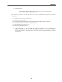
3. General specifications
!#& #
'$ & !( !! ! ! ,!!(,)),'*0&
!),)"
Applied
Device type
K7F-RBEA
K7F-RBOA
K4F-RBEA
G0L-SMQA
G0L-SMIA
G0L-SMHA
Detailed drawing
of mode switch
Description
Mode
!"
Function
Latches the last data during communication error.
#$%&'()*+,-.
Outputs user-defined data during communication
error (Default is data reset).
Mode
!"
Function
Latches the last data during communication error.
#$%&'()*+,-.
Outputs user-defined data during communication
error (Default is data reset).
Remark
1.
2.
All of the switches are set to off by factory default.
User can input user-defined data for communication error in KGLWIN.
(Refer to 6.6.7, Setting emergency output data of remote module.)
3-9
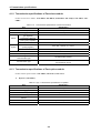
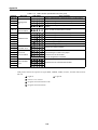
4. Transmission specifications
4.1
Transmission specifications of Fnet
4.1.1 Transmission specifications of Fnet master module
$!!%;$$(;$$0(@$$(6$$(2>$
Table 4.1.1
Electric
Optical
Transmission specifications of Fnet master module
Item
Specification
Transmission speed
1Mbps
common in Fnet module
Encoding type
Manchester Biphase-L
Transmission distance
(per segment)
Max. 750m
Transmission distance
(during using repeater)
Max. 750m × (6 repeater + 1) = 5.25 km
Transmission line
Twisted pair shielded cable
Transmission distance
(per segment)
Max. 3km
Transmission distance
(during using EOC)
Max. 3km × (6 EOC +1) = 21km
Transmission line
Optical cable
Max. number of station connection
Master + slave = 64 station
(At least one master should be connected)
Max. size of protocol
256 byte
Access type of
communication right
Circulated token passing
Communication type
Connection oriented service
Connectionless service
Frame error check
CRC 16 = X15 + X14 + X13 + ... + X2 + X + 1
4-1
4. Transmission specifications
4.1.2 Transmission specifications of Fnet slave module
$&!%
'
(')
'*+
$,'*+
$-'*+
$.
Table 4.1.2
Transmission specifications of Fnet slave module
Item
Electric
Optical
Specification
Transmission speed
1Mbps
Encoding type
Manchester Biphase-L
Transmission distance
(per segment)
Max. 750m
Transmission distance
(during using repeater)
Max. 750m × (6 repeater + 1) = 5.25km
Transmission line
Twisted pair shielded cable
Transmission distance
(during segment)
Max. 3km × (6 EOC +1) = 21km
Transmission line
Optical cable
Max. number of stations connected
Link master class + Remote slave class = 64
Max. size of protocol
256 byte
Access type of
communication right
Circulated token passing
Communication type
Connection oriented service
Connectionless service
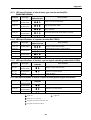
4.1.3 Transmission specifications of Fnet option module
$)!%*+
'*+
('*+
/
*+
Table 4.1.3(A)
Transmission specifications of repeater
Item
Specification
Communication speed
1Mbps
Encoding type
Manchester Biphase-L
Transmission line(Cable)
Twisted pair shielded cable
Max. extension distance per module
750m
Max. number of repeater between
stations
6 units
Max. distance between stations
5.25km(when 6 repeater is installed)
Frame error check
CRC 16 = X15 + X14 + X13 + ... + X2 + X + 1
4-2
4. Transmission specifications
0(1*+
(
Table 4.1.3(B)
Transmission specifications of electric/optical converter
Item
Specification
Communication speed
1Mbps
Encoding type
Manchester Biphase-L
Transmission line(Cable)
Optical cable, twist pair cable
Max. transmission distance
3km(Optical)/750m(electric)
Function of signal regeneration
Regenerating, Reshaping function
Frame error check
CRC 16 = X15 + X14 + X13 + ... + X2 + X + 1
2
1 3 4*+
/
Table 4.1.3(C)
Transmission specification of active coupler
Item
Specification
Communication speed
1Mbps
Encoding type
Manchester Biphase-L
Transmission line(Cable)
Optical cable
Max. transmission distance
3km
Function of signal regeneration
Regenerating, Reshaping function
Frame error check
CRC 16 = X15 + X14 + X13 + ... + X2 + X + 1
4-3
4. Transmission specifications
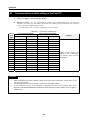
4.3
Cable specifications
4.3.1 Twisted pair cable for Fnet
)!)% 2> - ,(%!.
1".)/>!%2>>/>
Table 4.3.1
Specifications of twisted pair cable for Fnet
Cable contents
Product name
Low Capacitance LAN Interface Cable
Type name
LIREV-AMESB
Size
2 × 1.0mm (GS 92-3032, 18 AWG)
Maker
LG CABLE CO.,LTD
Electric characteristics
Item
Unit
Characteristic
Test Condition
Conductor resistance
Ω/km
21.8 or less
Normal Temp.
Withstanding voltage(DC)
V/min
Withstands at 500V for 1 minute
In air
Insulation resistance
MEGA Ω-km
1,000 or more
Normal Temp.
Static electricity capacity
pF/m
45 or less
1 kHz
Characteristic impedance
Ω
120 ± 12
10 MHz
Characteristics in appearance
Number of core
Conductor
Insulator
"
CORE
2
Specification
AWG
18
Configuration
NO./mm
1/1.0
Outer diameter
mm
1.0
Thickness
mm
0.9
Outer diameter
mm
2.8
Structural drawing
Conductor
Insulator
AL/Mylar Tape
Ground line
Braided
material
Sheath material
4-4
4. Transmission specifications
4.3.2 Optical cable for Fnet
)!% 2>$ - ,(%!.
1".0)/>!%2>$>/>
Table 4.3.2
Specifications of optical cable
Cable contents
Type name
Y22 : For indoor (for Bi-directional communication)
D22 : For outdoor (for Bi-directional communication)
Connector type
ST - Type
Maker
Hewlett Packard(H.P)
For indoor(standard)
For outdoor(standard)
Y22
D22
2.9 × 5.8
4.8
Loaded (cm)
5.0
7.5
Unloaded (cm)
Segment
Outer diameter (mm)
Min. Radius
of curvature
3.0
4.8
Weight(Kg/m)
16
21
Contents
Characteristic
Unit
Core
62.5
µm
Cladding
125
µm
Max. attenuation
5
dB/km
Standard attenuation
4.5
dB/km
CD%
Connector
type >D%! Connector
type
If the cable type
is Y226969,
connector
type is ST
and
the
Ex.)
!"
. E55CDCD
shape is stainless at both of the connectors.
( #$% "
Outside drawing of optical cable
For indoor(Y22)
For outdoor(D22)
4-5
4. Transmission specifications
L4
4.4
How to connect communication cable
4.4.1 Electric(twisted pair) cable connection
!" #
! $ %&'($)*+ $ " ,%&'($)*$--.
Shield wire
Shield wire
<Communication module A>
<Communication module B>
<Communication module>
<G0L-FUEA>
(Verify pin No. marked in connector to connect)
Fig. 4.4.1
Cable connection method of Fnet
4.4.2 Electric(twisted pair) cable connector connection
$ --/" 0 12
!
3%&'($)*
,
$--/"!
0,4.4/
#
"
Shielding wire(soldered)
Pin No.7
Pin No.7
Pin
No.6
Pin
No.6
Shielding
wire
Pin No.5
9-pin socket type
Fig. 4.4.2(A)
Connection of Fnet connector
9-pin socket type
Fig. 4.4.2(B)
4-8
Connection of G0L-FUEA connector
4. Transmission specifications
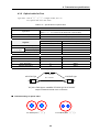
4.4.3 Optical cable connection
4
! 56 76 76 56
TX (Transmission)
TX (Transmission)
RX (Receive)
RX (Receive)
<Station A>
4.5
<Station B>
Terminal resistance
4.5.1 Electric network terminal resistance of Fnet
!
Resistance : 110
, 1/2 W
!
Connector case : Metal conductor plating type
Pin
No.7
Pin
No.6
Terminal
resistance
socket
type
9-pin
"
7 ..&
.2/8" " "
7 2
!%&'($4*" %&'($5*"
7
#
"
4-9
'('%
'
(
5-1
!
"
!
*
#$&#)
#
$#!$#
%&
!
(
!
(
!
!
*+,
(
!(!'
-
# . )-
*
$# #
)
.
*+,
!(
& # )$#$
)
*
5. System Configuration
(
!
MASTER-K PLC network system(entire system)
5.1
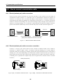
5. System configuration
5.2
Fnet network system
5.2.1 Configuration of Fnet master system (electric network)
"#
$%&'()
*
+
,(
!
Devices for network A (Fnet electric)
Type
Module name
Ex. of station number setting
FAM4.0
G0L-FUEA
0
K1000S
K7F-FUEA
1
K1000S
K7F-FUEA
2
K1000S
K7F-FUEA
3
K300S (K200S)
K4F-FUEA (K3F-FUEA)
4
PMU-500
PM0-500F
5
5.2.2 Configuration of Fnet master system (optical network)
$%&'
!"""#
!"""#
!"""#
For unused slot, dummy module(G0L-FADA) is attached.
Devices for network A (Fnet optical)
Type
Module name
Ex. of station number setting
Cable connection
GM1
K7F-FUOA
0
GM2
K7F-FUOA
1
GM3
K7F-FUOA
2
Active coupler
G0L-FACA/FABA/FAPA
Not available
Transmission#Receive
(Active coupler)
Receive#Transmission
(Active coupler)
5-2
5. System configuration
5.2.3 Configuration of Fnet master system
(network combined with electric/optical module)
&'
(
)(
*+
",+
!-""#
!$""#
!"""#
!"""#
!"""#
%
!"""#
!"""#
!"""#
Devices for network A (Fnet)
Electric
Type
Module
name
Optical
Ex. of station number
setting
Type
Module
name
Ex. of station
number setting
FAM
G0L-FUEA
0
K1000S
K7F-FUOA
7
K1000S
K7F-FUEA
1(slot 0)
K1000S
K7F-FUOA
8
K1000S
K7F-FUEA
2
K1000S
K7F-FUOA
9
G0L-FOEA
Not available
G0L-FACA
(Remark)
Not available
K1000S
K7F-FUEA
3
Optical/electric
converter
K300S
K4F-FUEA
4
Active coupler
K200S
K3F-FUEA
5
PMU-500
PM0-500F
6
Remark
1.
2.
Separate terminal resistance is unnecessary due to terminal resistance built-in inside optical/electric
converter.
Active coupler used in system configuration is consist of G0L-FAPA(Power), G0L-FABA(Base) and
G0L-FACA(Module). Module can be mounted up to 8 in the base, and dummy module(G0L-FADA)
should be attached for unused base to protect from foreign matter, dust, and the others.
5-3
5. System configuration
5.2.4 Configuration of Fnet slave system (electric network)
Devices for network A (Fnet electric)
Type
Module name
Ex. of station number setting
K1000S
K7F-FUEA
0(slot 0)
K1000S
K7F-FUEA
2(slot 0)
Devices for network B (Fnet electric)
Type
Module name
Ex. of station number setting
K1000S
K7F-FUEA
1(slot 1)
K1000S remote I/O
K7F-RBEA
3
K300S remote I/O
K4F-RBEA
4
Stand-alone remote
output
G0L-SMQA
5
5-4
5. System configuration
5.2.5 Configuration of Fnet slave system (optical network)
*&
&
!!"+
K1000S
*&
&
!!"+
!"""#()
!"""#()
!"""#()
Devices for network A (Fnet ,electric)
Type
Module name
Ex. of station number setting
K1000S
K7F-FUEA
0(slot 0)
Devices for network B (Fnet ,optical)
Type
Module name
Ex. Of station number
setting
K1000S
K7F-FUOA
1(slot 1)
K1000S remote I/O
K7F-RBOA
2
K1000S remote I/O
K7F-RBOA
3
K1000S remote I/O
K7F-RBOA
4
Active coupler
G0L-FACA/FABA/FAPA
Not available
5-5
5. System configuration
5.2.6 Configuration of Fnet slave system (electric/optical network)
, -
, -
, -
"
!"#
$#%&
#
$#!$#
#&
' *+
"
!"#
!"#
!"#
Devices for network A (Fnet electric)
Type
Module name
Ex. of station number setting
K1000S
K7F-FUEA
0(slot 0)
Devices for network B (Fnet)
Electric
Optical
Type
Module
name
Ex. of station
number setting
Type
Module
name
Ex. of station
number setting
K1000S
K7F-FUEA
1(slot 0)
K1000S remote
I/O
K7F-RBOA
5
K1000S remote
I/O
K7F-RBEA
2
K1000S remote
I/O
K7F-RBOA
6
K300S remote
I/O
K4F-RBEA
3
K1000S remote
I/O
K7F-RBOA
7
Electric/optical
converter
G0L-FOEA
Not available
Active coupler
G0L-FACA/
FABA/FAPA
Not available
Stand-alone
remote output
G0L-SMQA
4
5-6
5. System configuration
5.2.7 Configuration of Fnet combined system (electric/optical network)
$#%./
1.
*
-
2
'
*
*
-
-
*+
!"#
!"#
0
*
-
!"#
!"#
' !"#
5-7
!"#
5. System configuration
Devices for network A (Fnet, electric)
Type
Module name
Ex. of station number setting
FAM
G0L-FUEA
0
K1000S
K7F-FUEA
1(slot 0)
K1000S
K7F-FUEA
3
K1000S
K7F-FUEA
4
K300S
K4F-FUEA
6
K200S
K3F-FUEA
7
PMU-500
PM0-500F
8
Devices for network B (Fnet ,optical)
Type
Module name
Ex. of station number setting
K1000S
G0L-FUOA
5(slot 1)
K1000S remote I/O
K7F-RBOA
12
K1000S remote I/O
K7F-RBOA
13
K1000S remote I/O
K7F-RBOA
14
Active coupler
G0LFACA/FABA/FAPA
Not available
Devices for network C (Fnet ,electric)
Type
Module name
Ex. of station number setting
K1000S
K7F-FUEA
2(slot 1)
K1000S remote I/O
K7F-RBEA
9
K300S remote I/O
K4F-RBEA
10
Stand-alone remote
output
G0L-SMQA
11
5-8
6. Communication Function
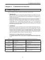
6.1 Programming method
In Fnet communication module, programming methods are divided into three :
–
High speed link
High speed link is used when other station’s data or information is exchanged in each given
time and cyclically. Self or other station’s data being in changing can be effectively used for
operating system through cyclically referring, and the communication can be performed only
through setting parameters.
For how to set, specify other station area and self area to be sent/received in parameter of
KGLWIN, specify data size, speed, and station number, and then perform communication.
For data size, 1(16 points)~12,800 words for Mnet, and 1~3,840 words for Fnet can be
communicated, and for communication cycle, 20ms~10sec. can be set according to
communicating contents. Because simple parameter setting enables communication with
other station, it is easy to use, and internal data processing is also high speed, thus many data
can be cyclically processed at a time.
–
Programming
High speed link is a cyclic communication, but the communication through function block is a
service that communicates when special event occurs to perform communication with other
station. It can be used when other station has error, which is sent to another station, or special
contact is entered to communicate. For how to prepare programming, using function block
according to data type previously created in KGLWIN program mode, specify the enable
conditions, the module position in which communication module is mounted, station number,
data area of self station, and other station area, and then prepare it.
Simultaneous use of high speed link and programming
For some data, high speed link and program can be simultaneously used for program when
the appropriate contents is sent if Tx/Rx of data are cyclically performed, and special event
occurs.
Table 6.1
Difference between high speed link operation and operation through function block
Contents
High speed link
Function block
1 word(16 points)
Available according to data type
Ex.) Bit, Byte, Word…
20ms~10sec.
Used whenever function block enable condition is started up.
Specifying station
number
Used by setting station number of the
front of communication module in
parameter
Fnet uses the station number of the front of
communication module, and Mnet uses MAC
address.
How to operate
Parameter setting!downloading to
PLC!high speed link allowed!RUN
Compiling!downloading to PLC!RUN
Used if high speed link is allowed even in
state that CPU module is RUN, STOP,
and PAUSE.
Performs operation according to operation
mode of CPU module.
Basic unit of Tx/Rx
data
Communication cycle
Control through CPU
operation mode key
6. Communication Function
6.2 High speed link
6.2.1 Introduction
!"#$%& !#'()*+,- .
Function of high speed link block setting :
) %-/0
122 34,5(!(6/+
1 3-
170+34,5(!6
-
Function of Tx/Rx period setting :
8 2+ )+9
Function of Tx/Rx area setting :
Function of high speed link information :
' /-2-)
-,
)Table 6.2.1
Item
Max. communication point according to device type
Max. number of
points for
communication
Max. number
of points for
transmission
Max.
number of
blocks
Max. number
of points per
block
Remarks
60 words
Identical
value for
electric and
optical
K7FFUEA/FUOA
Fnet
communicat
-ion module
K3LRBEA/RBOA
K4F-FUEA
3840 words
1920 words
K4L-RBEA
K3F-FUEA
G0L-FUEA
64 blocks
6. Communication Function
6.2.2 Setting sequence of high speed link
Project
Select standard screen of
project
Select standard screen of project in KGL-WIN screen
↓
High speed link parameter
High speed link 1 ~ 4
Select (4 can be set in K1000S,
2 in K300S, and 1 in K200S)
↓
High speed link setting(link setting)
Input network type, slot number that communication module
is mounted, and self station number with decimal
Link-enable
Self station number(0~63)
Slot number(0~7)
Unit type
• MASTER-K Fnet
↓
In case of local connection, select self-station number for
transmission and select other station number for receive
In case of remote connection, select other station number
regardless of Tx/Rx.
High speed link setting
(registration list)
Station number(0~63)
Block number(0~63)
Unit type
• Local Out
• Local In
• Remote Out
• Remote In
Transmission range/ Receive
range
Each of Tx/Rx can select 32 block number, contents of Tx/Rx
data can be distinct and selected by mutual block number in
local connection.
Only one of Tx/Rx should be selected in case of local
connection, and all of Tx/Rx can be selected in remote
connection.
Size(1~60 word)
Tx/Rx period(200ms~10sec)
↓
Online(After local connection)
Download
• Parameter
Select program or program and parameter, and download to
CPU.
• Parameter and program
↓
Mode switch
Switch operation mode to RUN
mode
Other station should be set
~
(These setting is
unnecessary if other station is remote station).
Program using emergency flag, etc. should be prepared for
communication cut-off, error occurrence of other station, and
instant power failure of remote module.
6. Communication Function
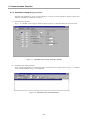
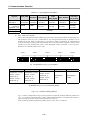
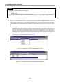
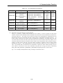
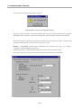
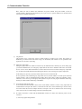
6.1.3 Parameter setting of high speed link
,
: !"# - , 9 .
)
;:!"#
6-/-)-)::
-
Fig. 6.1.1
2
Standard screen of KGL project(for K200S)
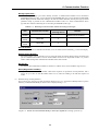
,
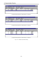
%
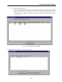
#;,#)!"#:6-/-)-)
#;6-/-)-2
-
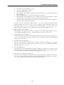
Fig. 6.1.2
Standard screen of link parameter
6. Communication Function
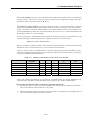
High speed link1 :
- 0 34,5(!)++,<;8-234,5(!1++,)34,5(
!2++,-
- /-)-2 -34,5(!<;8Table 6.1.2
Mounting of communication module according to CPU type
Item
Communication module
Max. number of
mounting devices
MASTERK1000S
K7F-FUEA, K7F-FUOA
4
MASTERK300S
K4F-FUEA
2
MASTERK200S
K3F-FUEA
2
Remarks
Each of communication
module can be combined.
Link Enable :
,
5
=>
=?>-
Self Station Number :
,
+/1
-
Slot No :
,
-4
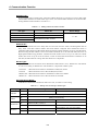
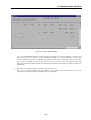
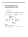
+@No(Registration number) :
9 - /0 + /1 9 1 '
%
&-)
6-/-)-2
3
5#;3%
6-/-)-1-
Fig. 6.1.3
Screen of Link Parameter Modify or Insert (for register No.1 of 1)
6. Communication Function
Station No :
% -%
,
/-)-1-
Table 6.1.3
Setting method of station number
Unit Type
Station No
Local Out
Self station number
Local In
Other(Local) station number
Remote Out
Station Range
0 ~ 63
Other(Remote) station number
Remote In
Block No :
- , -A
A4
&-&-
,
- 12 12-
12-%
&-&-
-
Unit Type :
-%
BCDB
%D-,BCDB%D
3• #
C
• #
%
• C
• %
.$
.$
.$
.$
-
Tx/Rx Device Name :
'&
/-2-0Table 6.1.4
Unit Type
Mode
Tx
Setting area according to station type
Available setting area
Remarks
Transmission area of self station
All area of P,M,L,K,F,D,T,C
Local Out
Rx
Setting is unnecessary
Tx
Setting is unnecessary
Local In
Rx
Area of P,M,L,K,D,T,C
Receive area of self station
Tx
All area of P,M,L,K,F,D,T,C
Transmission area of self station
Rx
P area
Receive area of remote station
Tx
P area
Transmission area of remote station
Rx
Area of P,M,L,K,D,T,C
Receive area of self station
Remote Out
Remote In
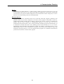
6. Communication Function
No :
))/ 6/+
32++-%
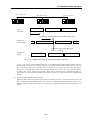
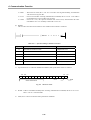
Tx/Rx Period :
;#< - % ;#< 9 - 2+)+-
- 6 2++ 2++- % ;#< ;#<-
6. Communication Function
6-/-)-0
-
SCAN TIME (x)
Transmission period set (y)
Transmission
delay (z)
Transmission start
.E( '
;#<
Transmission period set (y)
SCAN TIME (x)
Transmission start
.E+ '
;#<
Fig 6.1.4
Scan of PLC program and transmission period
%
8&F#%&!#%&!FC8A#5
?F3C'5
BCDBCD-$
-
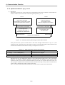
6.1.4 Operation of high speed link
%
C!
-4
6-/-)-2
G5
G- 6- /-)-* C(
'
6-/-)-26-/-)-*
-
6. Communication Function
#'
;#<,C;-%
;#<-A;#<<;8
(
C
;#<
/-)-*-
Table 6.1.5
Relation between PLC mode and Mode
Parameter download
Operation of high speed link
RUN
X
O
STOP
O
O
PAUSE
X
O
DEBUG
X
O
Remarks
If is allowed, will be
operated regard less of
PLC mode.
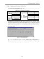
6.1.5 Information of high speed link
)
6
- - &
8&F#%&! #%&!FC8A#5 ,F,45?F3C'5'5H%<5F3C'5'5HF5C
/0 - 8 - %
;#< (##(
6
/-)-/-
6. Communication Function
Table 6.1.6
High speed link information
RUN_LINK
LINKTROUBLE
Tx/Rx status
(TRX_MODE)
Operation
mode
(DEV_MODE)
Error
(DEV_ERROR)
Type of
information
Entire
information
Entire
information
Individual
information
Individual
information
Individual
information
Individual
information
KEYWORD
_HS
RLINK
_HS
LTRBL
_HSTRX[n]
_HSMOD[n]
_HSERR[n]
(n=0..63)
(n=0..63)
(n=0..63)
_HS
STATE[n]
(n=0..63)
Segment
(
=number of
parameter, 1~4)
Monitor
Available
Use of program
High speed
link status
(HS_STATE)
8&F#%&!F,#%&!
BCD
(
BCD
D8&
- BCD BCD
(
BCD-
station 1
station 2
(a)
Station 1
Transmission : 2 word
Receive : 2 word
(Station No. 2)
Receive : 2 word
(Station No. 2)
station 3
station 4
station 5
Station 4
Station 5
Transmission :
2 word
Transmission :
2 word
Configuration of system
Station 2
Transmission : 2 word
Receive : 2 word
(Station No. 1)
Receive : 2 word
(Station No. 4)
Station 3
Transmission : 2 word
Receive : 2 word
(Station No. 1)
Receive : 2 word
(Station No. 5)
(b) Example of parameter setting
Fig. 6.1.6
Condition of RUN_LINK On
6-/-)-/
8&F#%&!
BCD- % * 3
6- 6- %8&F#%&!)BCD
.
6. Communication Function
#(
) BCD
,
) 8&
,
) '
) 21
C21 ) 8&
,
8&
%@8&F#%&!)BCD-%;#<
8&F#%&! - C
8&F#%&! BCD (
BCD- 8 #%&!FC8A#5
#%&!FC8A#5F,#A#
%8&F#%&!BCDD
8&F#%&!BCD
#%&!FC8A#5BCDBCD-
,F?,45=+--/1>
%
BCD BCD-
CF,3C'5=+--/1>
-/0 - % 8& BCD- % ,C;;48,5'5A8"
BCD-
5F,5=+--/1>
-/0 - 5 ;#<D
-C
BC
BCD-
,
F,,45=+--/1>
-&
BCD
8&-
BCD
D
-
6. Communication Function
Remark
Among keyword name used in items of (a)~(f)
: Shows number of used in parameter setting(If communication module is 1 unit, 1 is
normally used).
[0..63] : Shows registered number of individual parameter(This can be used to monitor communication state
according to each parameter of 0~63 or this can be used in program).
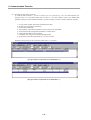
2
%
3 $ % !"#--6
6
3
3 $ -,
6
3
$
6
3!"#-%
6
33$C(
6
3
6- /-)-@ 5 6
- 8 6
-,
-%6-/-)-@6
36-/-)-7%-
Fig. 6.1.7
Fig. 6.1.8
Flag Monitor screen and Register Flag screen
Flag Monitor screen(the state that flag is registered)
6. Communication Function
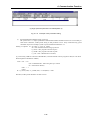
3%
%
%C(
6-/-)-I-#++-,++
++++
;) + &-+ #+)-+)
+)+)
);2-
Fig. 6.1.9
High Speed Link Parameter
(c) Monitoring ‘link information’ in read information menu.
6. Communication Function
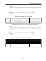
6.1.6 Speed calculation of high speed link
)
%
-A
6-/-)-)+PLC-A
PLC-B
User Program Scan Data
Data is received from
is transmitted to communication module
communication module
when User Program Scan is finished
when User Program Scan is finished
Communication module(station 1)
Communication module(station 2)
User Program Scan
Transmits data to PLC
Transmits when token is
received from master station
after data receive
Data transmission
Data receive
Communication cable/Modem
Fig. 6.1.10
Data transmission path through communication module
6- /-)-)+ -3
/-)-@-
Table 6.1.7
Data transmission path and time elements
Path
Time affecting elements
PLC CPU(A) Com. module(station 1)
Scan time of PLC-A program
Comm. module(station 1) Com. module(station 2)
Scan time of comm. + Scan time of comm. O/S
Comm. module(station 2) PLC CPU(B)
Scan time of PLC-B program
' ;#< <;8 ;#< <;8 ;#< - ;#< ;#<!"#C(
--
-<
6-/-)-));#<-
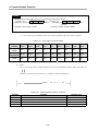
6. Communication Function
T1
TscanA
PLC-A
Scan time
TscanA
TscanA
Delay time of PLC scan(Tdelay_plc1)
Delay time of communication scan transmission(Tdelay_com)
T2
Scan time of
communication
Tcom_scan
Tcom_scan
Tcom_scan
Delay time of PLC scan(Tdelay_plc2)
T3
Scan time of
PLC-B
TscanB
Fig. 6.1.11
TscanB
TscanB
Relation between PLC and communication in scan time
% 6- /-)-)) ;#<(4 ) ;#<(4
F
)
-<
;#< F - F)-<
;#<(A;#<
F
2 - A 2- '
--C,
2 ,
-
;#<(4;#<(A-,
-C )+ *)2 - .
6. Communication Function
,
% )+ *)2 9 59/(),E;F4J<FJ;FA 59/-)
,E-
;F4E-;#<4
;FAE-;#<A
<FE-
<E , 59/-2
E
.)
,E
<
% )+ *)2
59/(1,E5 &J3 59/-1
5E5
EC
&E
3E3
.
5E, & 59/-0
,E
&E&
6.)-* 3.)-2
EC
.
6.7 3.)-/
&E&
63.
K6.,
J&
2*/
K3.,
J&
)+20
3E3
D
C,
-
.
K6.)/ 3.*+
6. Communication Function
6.1.7 Ex. 1) : High speed link between PLCs of Fnet
%C 6/-)-/34,5(!66-*-2-2Table 6.1.6
I/O configuration and Tx/Rx flow
Tx/Rx structure
K1000S
(station 0)
K1000S
(station 1)
K1000S
(station 2)
I/O configuration
Transmission area
Receive area
P3, P4
-
-
D0100
P3, P4
-
-
D0100
TX : → K1000S(station 0)
P3, P4
-
RX : ← K1000S(station 1)
-
D0100
TX : → K1000S(station 1)
RX : ← K1000S(station 2)
TX : → K1000S(station 2)
RX : ← K1000S(station 0)
Slot 0 : Master
Slot 1 : OUT 32 points
Slot 2 : IN 32 points
4
!)+++, <;8 2 2 '+)++'+)+)
;);2 )-<
6- /-)-)* 6- /-)-)/- %6
!1++,-$!2++,'
;
Fig. 6.1.15
User program of Ex.1
6- /-)-)* 5-)- % 8&F#%&!E) #%&!FC8A#5E+ '+)++ '+)+) ;++) ;++2- % #%&!F5A#5E) 6666 ;++)- , /-)-/
8&F#%&!#%&!FC8A#5 -
6. Communication Function
;
) 2 1 /-)-/ 6- *-2-2 6- /-)-)* /-)-/- 6 ;#<-C
9.
)
2
1
0
*
/
@
7
4
;
;
,
!"#
5
C(
<8&C(
<
5&-) ;
5-)
.
(A) High speed link parameter of K1000S(station 0)
(B) High speed link parameter of K1000S(station 1)
6. Communication Function
(C) High speed link parameter of K1000S(station 2)
Fig. 6.1.16
Example of link parameter setting
,
5-)
2
- /-)-*&
9 ,E;F4J<FJ;FA
,E-
;F4E-
4
;FAE-
A
<FE-
;F4;FA!)+++,;#<*
;#<!"# <E ,
E
.)
,E
E7 1
E20
,E;F4E* J;FAE* J<20 E10
10-
6. Communication Function
6.1.9
of
Ex. 3) : High speed link between master + slave + single remote I/O stations
Fnet
,
6-/-)-)7
%C(4A;#<
34,5(!6-
Fig. 6.1.18
Combined class system of MASTER-K Fnet master/slave
%4
2-&A
%C- % + ) (4)!)+++,(
<;8+ !)+++,(<;82 -3)(A
10
*
%C
10*
) - ) 10
*-,
(
/-)-7
%C
-
6. Communication Function
Table 6.1.8
PLC type
K1000S CPU
I/O configuration
Tx/Rx relation of Local/Remote
Transmission
area
Receive
area
Slot 0:master(station 0)
Local transmission : master(station 2)
Remote Tx/Rx : slave 3(station 3)
Remote Tx/Rx : slave 4(station 4)
Remote transmission : stand-alone
remote(station 5)
D1000
D1100
D0000
D0010
D0200
D1000
D1100
network A
Slot 1: master(station 1)
network B
K1000S CPU
I/O configuration and Tx/Rx flow
Slot 0:master(station 2)
network A
Local receive : master(station 0)
D0000
K1000S slave
Slot 0:OUT 32 points
Slot 1:IN 32points
Local : K1000S(station 1)
P0, P1
P2, P3
K300S slave
Slot 0:OUT 16 points
Slot 1:IN 16 points
Local : K1000S(station 1)
P0, P1
P2, P3
Single
Remote
OUT 16 points
Local : K1000S(station 1)
P0, P1
;
% 6- /-)-)7 ) 1 0 * %C- ('++++'+)++'+2++;+;)!)+++,(
!1++,(
%C- ;2;1!)+++,(
!1++,(
')+++'))++2!)+++,(<;84- )
!)+++,(
!1++,(
%C- %C
(
(-4
!)+++,(<;8) -4 4A 6-/))I
<;8 !)+++, !)+++,- H 8&F#%&!#%&!FC8A#5F,+#%&!F,+#A# C(
6-/-)-)I
5-1-
6. Communication Function
(a) High speed link parameter of master station 0 in network A
(b) High speed link parameter of master station 2 in network A
(c) High speed link parameter of master station 3 in network A
Fig. 6.1.19
Example of parameter setting
6. Communication Function
Fig. 6.1.20
Slave Tx/Rx program
6- /-)-2+ !)+++, ;#<3 + 1- % 1 0 1 0 9'+2++
*- (
( 2 (
;
6- /-)-2) 1 - ,
D (
-
6. Communication Function
8&F#%&!
-%8&F#%&!BCD
D%C
-
-,
F6,3F5,5
6-/-)-2)
-
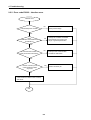
Fig. 6.1.21
SLAVE3 POWER OFF START PROGRAM
%F6,3F,F&C
F6,3F5,5-%
B)DB+D
-BD
+ @- 1 8&F#%&!B)DF,2?B)DF,23C'5F,25B+D
- 1 F6,3)F,F&C F6,3)F5,5B)D-%F,23C'5F,2?B)D
F6,3)F
5,5B+D- 4
= > -%
%6-/-)-2)B=)>D+)6- /-)-22 0 - % -
6. Communication Function
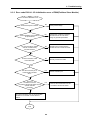
Fig. 6.1.22
SLAVE4 POWER OFF START PROGRAM
6. Communication Function
6.2 Communication instructions
6.2.1 Introduction
<
-
;#<
;#< -
-
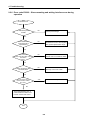
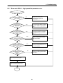
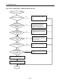
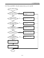
6.2.2 Using sequence of communication instructions
Project
Creates a new project or open existing project in KGL screen
Creates or opens program
↓
Preparation of program
Prepares program with
Ladder/Mnemonic
Check station number, slot position, I/O module address, etc.
of communication module in self station and other station, and
prepares relevant flag combined with program for emergency
↓
On-line connection
Local connection
↓
Download
Download
• Parameter and program
↓
Mode switch
Operation mode to RUN
Configure
in other station(if other station is remote
station, this is unnessary)
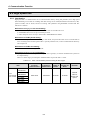
6.2.3 Type of communication commands
< 0 - 54' $%563<C&&5<3
-;8"5
A54 AC4 - /-2-) -
6. Communication Function
Table 2.2.1
Type of communication command
Type
Usage
Available unit
READ,
WRITE
Reads data of other station or writes data to other station
STATUS
Checks present status of MASTER-K PLC
RPUT, RGET
Reads or writes data in internal memory of special module
FUEA, FUOA,
MUEA
RBEA, RBOA
54'
-)
.
Table 6.2.2
Operand
Operand setting of READ command
Contents
Available area
sl
Slot number of FUEA to read
Integer from 0 to 7
st
Other station number to read
M, P, K, L, F, T, C, D, #D(see Remark)
D
Area of self station to store data which is read
M, P, K, L, T, C, D, #D
S
Other station area to read
M, P, K, L, F, T, C, D
n
Word number of data to read
Integer, D
Indication of link status information(see Remark)
M, P, K, L, T, C, D, #D
SS
Remark
Area of st can’t be set with decimal and occupies 4 word, and this shouldn’t be duplicated, so user should
note this.
,,,# .
Fig. 6.2.1
Structure of SS
6. Communication Function
&'
5
,
. ,,BCD)
BCD
. %BCD)-'
. % BCD &'BCD
5ABCD-
$%5
-6
.
!" Table 6.2.3
Operand
Operand setting of WRITE command
Contents
Available area
sl
Slot number of FUEA to write
Integer from 0 to 7
st
Other station number to write
M, P, K, L, F, T, C, D, #D
D
CPU area of self station to write
M, P, K, L, T, C, D, #D
S
Other station area to store data which is written
M, P, K, L, F, T, C, D
n
Number of data words to write
Integer, D
Indication of link status information
M, P, K, L, T, C, D, #D
SS
,
54',,
.
Fig. 6.2
Structure of SS
'C&5. %
BCDBCD)
&',5.
54'-
6. Communication Function
,48,
-C
.
""# Table 6.2.4
Operand
Operand setting of STATUS command
Contents
Available area
Sl
Slot number of FUEA to read information
Integer from 0 to 7
St
Other station number to read information
M, P, K, L, F, T, C, D, #D
D
Area of self station(10word) to store data which is read
M, P, K, L, T, C, D, #D
Indication of link status information
M, P, K, L, F, T, C, D
SS
,,
54'
')+-,441-1
B'D "5
- , .
$" Table 6.2.6
Operand
Operand setting of RGET instruction
Contents
Available area
sl
See Remark
Integer (Hexadecimal)
St
See Remark
Integer (Hexadecimal)
D
Area of self station to store data which is read
M, P, K, L, T, C, D, #D
S
Internal memory area of special module in remote station
Integer
to read
n
Number of data word to read
Integer, D
Indication of link status information
M, P, K, L, T, C, D, #D
SS
6. Communication Function
Remark
Hexadecimal is used in setting of sl and st, and standard format is as follows:
%
&
'
Upper(AB) : Type of special module in remote station.
Lower(CD) : Slot number of FUEA
%
&
'
Upper(AB) : Slot number that special module is
mounted
Lower(CD) : Station number of RBEA
<
/-2-/
-
Table 6.2.7
Module
(K1000S)
Code
value
K7FAD4A
K7FAD3A
K7FAD4B
K7FDI4A
K7FDI3A
K7FDV4A
K7FDV3A
K7FTC4A
K7FRD3A
h00
h40
h0A
h01
h41
h02
h42
h03
h04
K4FAD3A
K4FDA1A
K4FDV2A
K4FDV3A
K4FDI2A
K4FDI3A
K4FTC2A
K4FRD2A
hC0
h81
hC3
hC4
hC1
hC2
h83
h84
Module
K4F(K300S/200S) AD2A
Code
value
Code value of special module
h80
;8
,,
"5 .
(#" Table 6.2.8
Operand
D
Operand setting of RPUT command
Contents
Available area
Area of self station to store data which is written
M, P, K, L, T, C, D, #D
S
Internal memory area of special module in remote station to write
Integer
N
Number of data words to write
Integer, D
Indication of link status information
M, P, K, L, T, C, D, #D
SS
6. Communication Function
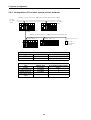
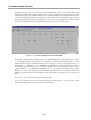
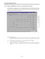
6.2.4 Usage of read/write commands in Fnet PLC + PLC system
!)+++,<;8
+ <*-2-234,5(!6
!)+++, <;8 ) !)+++, <;8 2
6 54' $%5
!)+++,<;8+
4:
.
. ,)'++++!)+++,)
. ,2'+++0!)+++,2 0'++++L'+++1
)'+++0L'+++@2
. )+'+)++6854)'++++6854
+'+*++'+*+I
3+++
54'
. $*'+*++
6854
+*
'1+++1++0 6854 13++) $%5
. <54'$%5
. <&'54'
. <'C&5$%5
. <54'
. <$%5
6. Communication Function
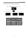
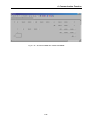
6.2.5 Usage of RGET/RPUT in Fnet PLC + remote I/O(special module)
!)+++,<;8+ <
*-2-0 34,5(! 6 - 4' %C
4' -
. $
. $ '+)++ '+)+) &- + &- )1 4' +A5416854
). <
3+)+3+2+'C&5
. 6
;8
. ,)+&-)0
4' +A54
1 6854 ) )+ ')+++ -
6. Communication Function
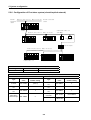
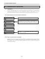
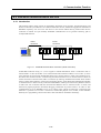
6.3 KGLWIN communication service
6.3.1 Introduction
;#<6
!"#$%&- 5
- !"#$%& -
Actual
connection
Virtual
connection
KGLWIN
PLC A
PLC B
PLC C
Fnet
Fig. 6.3.1
KGLWIN communication connection (virtual connection)
% !"#$%& 6- /-1-) ,212< ;#< 4
;#<4;#<A;#<<63-;#<4
C(
!"#$%&;#<4-4
;#<4;#<<-%
C(
;#<< ;#<4
;#<4
!"#$%& -
,212<6
- ,212< ;#< < ;#<<;#<4-
!"#$%& ;#<- < ;#< ;#< (-M
-
6. Communication Function
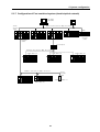
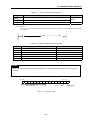
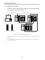
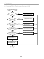
6.3.2 KGLWIN remote connection
4
;#< !)+++, %C !1++, %C 34,5(!
!"#$%& - !"#$%& )2
<)2
.
connection
1 connection
Local
Remote
)$*!
Module
Fnet
Mnet
+module
module
2,connection
Remote
Fig. 6.3.2
KGL remote connection(remote 1 and 2)
6-/-1-2);#<4;#<A 2;#<< -
(
-%
B<D
B;:KCD-
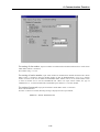
6. Communication Function
;#<
),
6-/-)-2+-
;#<
) ;#< A ++5+I)+++++) 6- /-)-2- ,
34,5(!3
34,5(! 6- $ B++5+I)++NNNND
BD
-
;#<),
BC!D%)
!"#.
53C5)O!2++,O53C5,C;
6. Communication Function
%
.
(Communication line error / internal protocol error)
%;#<)<;8:
-%;#<P
-
)
,212<
-4
C(
-
Q 2 CM(
- % 6- /-)-2 2
9.
!"# 3;#<4 3;#<A 6;#<A 6
;#<<
62
<C(
2
.
6. Communication Function
,
&)
+
;#<4
;#<4 ;#<A-%
&2
)
;#<A
2;#<A ;#<<-
)2
-%++5+I)+++++);#<A)*
;#<<2-,
34,5(!6-$BRRRRRD
BD
%
C!
!"#53C52O!2++,O53C5,C;
2
,212<
;#<5-8
C(
/-1-) 9 <
,212< !"#$%&, 936Table 6.3.1
Relation of roles between client and server of KGLWIN
Server Client
PC-module
(KGLWIN)
K1000S
K300S
K200S
K1000S remote
I/O
K300S remote
I/O
PC-module(KGL)
X
O
O
O
O
O
K1000S
X
O
O
O
O
O
K300S
X
O
O
O
O
O
K200S
X
O
O
O
O
O
K1000S remote I/O
X
O
O
O
O
O
K300S remote I/O
X
X
X
X
X
X
,212< !)+++, %C- &
!"#$%& ;#<!)+++,L!2++,!)+++,%C
!1++, )
$: !"#$%& <;8 )
2
2
$)2
:
-
6. Communication Function
1
2-2
-
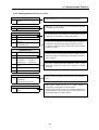
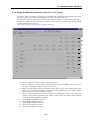
6.3.3 Functions on connecting KGLWIN to remote I/O station
%C!"#-$
%C
!
N,
;#< C(
N%CC(
N6
N,
N,%C;
,
;#< %C
;#<C(
-
%
"#$
,
%C"%
C,&-%C& < &- ;#< %C,-
6. Communication Function
"&
'$!
"
&()#
)#
&)#
*
#( *('
)'
+#( *(
C%C8&,C;
8&.
,C;.%C
<!"#%C
.!"#%C
#
.%C,
#.
8.
<
3-43-<&-<&-< -%
< &- &4! %
-
%C
%C
6,3
%CC(
-
6. Communication Function
%C ,
3
%-
6
6,3- % 3 C(
- ,
40-1
-
5
5%C
-%
-%
$%C(
;
5%
%
= >C
C!%
D !"#$%&-
;
;
%C - ,
3 C(
$ A ' <
; - 6 ;<<%C'-
% !)+++,!1++, %C .
$
6. Communication Function
C
N N #
N N 6%C
N ,
N 6
N#
N3
6
,
33
%C
6.3.4 Slave system flag
% 6,3 ,
4
7. Diagnosis function
7.1
Self diagnosis function of Fnet communication module
7.1.1 Self diagnosis function during running
!
"#"
Items
Contents
Remark
Diagnosis function
(Initial self
diagnosis)
** On-line mode **
1) Memory access error of communication module
2) Common RAM access and Reading/Writing error
3) Interface error of PLC and IBM_PC
4) Frame error during communication
5) Error status in physical layer of other station during communication
6) Error in physical layer of self station during communication
7) Program execution error during communication
Error code is
displayed through
LED when error
occurred
(See Appendix
A1.1/A1.2)
Diagnosis function
(Communication
diagnosis)
** Test mode **
1) Diagnosis of network configuration status in physical layer by test.
– Transmission error of physical layer
– Receive error of physical layer
2) Interface error of CPU in communication module and communication
chip.
Error code is
displayed through
LED when error
occurred
7.1.2 Communication diagnosis by test mode
$ % % %&! CPU-A
CPU-B
Input 32 points
Output 32 points
Output 16 points
FUEA(station 1)
Fig. 7.1.2
K1000S
POWER
Input 32 points
Output 32 points
Input 16 points
FUEA(station 1)
K1000S
POWER
Operation mode : TEST 1
Operation mode : TEST 2
Configuration of test system
7-1
7. Diagnosis function
'
$
"' ()*+()*+,
-
!5-
$ " ()*+ ()*+, .
/
()*+01#121
#
()*+2(
/
()*+,01#1!23"
4"
#
()*+,2(
)()*+()*+,
()*+.
During communication test
One LED rotates
at a time(total
rotation number
256)
RUN = Light on
LAS
TOKEN
TRX
FAULT
Result of communication test
RUN = Flash
LAS = Light on only if receive error occurred
TOKEN = Light on only if transmission error occurred
TRX = Light on if TIME OUT occurred
FAULT = Light on if frame error occurred
%*1+136+1789+#+ %*1
!:; 3*9 1 " 1 <-
()*+,.
During communication test
One LED rotates
at a time(total
rotation number
256)
Result of communication test
RUN = Light off/Flash
LAS
TOKEN
TRX
FAULT
RUN = Whether error occurred or not
LAS = No meaning
TOKEN = No meaning
TRX = No meaning
FAULT = No meaning
%*1+136+1789+#+%*1
!:; 3*91
3*9
3*9
$ $ #"
7-2
8. Installation and testing operation
/#13+8 )( ()* ()*.
Table 8.1
Mounting of communication module according to CPU type
Mountable device type
Max. mounting
number
Mounting location
(slot)
K7F-MUEA, K7F-FUEA, K7F-FUOA
4
Main base I/O
K7F-RBEA, K7F-RBOA
1
CPU
K4F-FUEA
2
Main base I/O
K4F-RBEA
1
CPU
K200S
K3F-FUEA
2
I/O
FAM4.0
G0L-FUEA
1
16 bit extended slot
Mounted in PC
CPU type
K1000S
K300S
Remark
Remote I/O
Remote I/O
FAM4.0
G0L-MUEA
1
16 bit extended slot
Mounted in PC
-
G0L-SMQA
1
Stand-alone type
Remote output
-
G0L-SMIA
1
Stand-alone type
Remote input
-
G0L-SMHA
1
Stand-alone type
Remote
combined
8.1.1 Installation of Fnet master module
-
$
8&%+%*8<%+%*
85%+%* 8&%+%*7 =>+%* $,/+)((
<8>>>#)(
!-
(
! 85>># 8!>># )(2
"
-
5-
=>+%*
;$,/)(
4
"42#5!5=>+%*
-
8-1
8. Installation and testing operation
8.1.2 Installation of Fnet slave module
$"
8&%+3,8<%+3,
8&%+3,72=>+#/?=>+#/$=>+#/'-$ 7
;
%@!
"/8
Main base
Fnet
network
Extended base
Extended base
Fig. 8.1.2
How to mount and install
1@!
%#/
Table 8.1.2
Mountable device in FSM
Available module name
Product name
Not available module name
Product name
Type name
All types of I/O module
D/A conversion module
Interrupt input module
K!F-INTA
Temperature conversion module
Fnet module
K!l-FUEA/FUOA
PID control module
K!F-PIDA
Analog timer
K!F-AT!A
PC communication module
K!L-CUEA
High speed counter module
A/D conversion module
#
()*
8-2
8. Installation and testing operation
8.1.3 Installation procedure of Fnet module
-
$ ""
!-
1
5-
<-
4 ()*
:-
( /
% " 8>>># ,
<
;-
A"
"
$"()*
&-
# 1
@-
(
(79
(79!
2%.>Ω-
B-
$
(79(79!
>- 1
$8=$9
- A "
!- (
)(
$#
" )( $
)("
2# 5!5 =>+%* - #
"
5- 1
)(
8-3
8. Installation and testing operation
8.1.4 Cautions on installation of Fnet module
!-
5<:;-
"
$
$ 3
$ %
* (
1
$
$ &-
,
@-
(
8-4
8. Installation and testing operation
B-
(%=)(
"
FG
Remark
If communication status is bad when connection is made as above, this is caused by serious noise from FG.
Therefore, user should eliminate its cause or not connect to FG.
>- $
"
- # 2 - B2#<<2--
!- 7 16 36 ( 1 3 $ 1 3 2#<557-
Optical cable
5- %
"
"
<- $CB1
4
$
#"
8-5
8. Installation and testing operation
8.1.5 Preparations during testing operation of Fnet module
1%
Items to be checked
Mounting check of
Base module
Connection status of
Communication cable
Contents
– Does using voltage of power module comply with specifications of power module?
– Is battery of CPU module connected?
– Is mounting of all base modules perfect?
" See product manual according to each PLC type.
– Is connection status of communication cable perfect?
– Is connection type of each cable open loop?
Module mounting
– Is mounting status of communication module which is mounted in basic base perfect?
Switch checking
– Is the status of mode switch On-line(switch value is 0)?
– Is station No. switch correctly set?
– Is master station No. switch correctly set? (for slave module)
– Is output option switch correctly set when communication is cut off? (for slave module)
Items to be checked
Contents
Standard check
– Is PC appropriate IBM-PC compatible?
– Has PC sufficient environment to install FAM4.0/KGLWIN?
– Has PC space and empty slot to mount this module?
– Can memory map of PC reserve empty space to use this module?
" See user’s manual of FAM4.0/ KGLWIN and Appendix of this manual.
Module mounting and
FAM4.0/KGLWIN installation
– Reserve empty space of 32K byte in memory map of PC, select this area for the
memory switch of this module, set port address.
– Mount and fix this module into the slot to be inserted.
Switch recheck
– Are memory switch and port switch correctly set?
– Is mode switch set to On-line(switch value is 0) status?
– Is station number switch correctly set?
8-6
8. Installation and testing operation
8.1.6 Testing operation procedure of Fnet module
1D
)(
Starting
Power on :
(1) Check input power.
(2) Check the connection of communication cable.
(3) Power on.
(4) Check power LED light of power module.
(5) Check LED status of CPU module
" If abnormal, see Troubleshooting of manual according to each PLC type.
(6) Check whether LED status of communication module is normal or not.
" If abnormal, see Chap. 9 Troubleshooting of this manual.
Programming :
Programming is prepared in KGLWIN, and it is written into CPU module.
(Properly use flags that are related to emergency action for communication cut-off during communication with
other station and monitoring of other station)
Sequence check :
Checks operation of communication module according to program.
Program correction :
Corrects if there is any error of sequence program.
Program preservation :
(1) Stores program into floppy disk or hard disk.
(2) Prints circuit drawing and list with printer.
(3) Writes program to memory module, if necessary.
End
8-7
8. Installation and testing operation
Starting
Power :
(1) Check input power.
(2) Check the connection of communication cable(when cable is connected).
(3) Power on.
(4) Check booting status of PC.
" If abnormal, see Chap. 9 Troubleshooting of user’s manual in FAM4.0/KGLWIN.
(5) Check whether LED status of communication module is normal or not.
" If abnormal, see Chap. 9 Troubleshooting of this manual.
(6) Check whether this module is initialized or not by executing FAM4.0/KGLWIN.
" See user’s manual of FAM 4.0/KGLWIN.
(7) Check LED status of this module.
" See ‘Appendix LED status’ of this manual.
If the operation is abnormal, see chap. 9 Troubleshooting.
(8) Preparation and execution of program to be executed.
" See user’s manual of FAM4.0/KGLWIN.
If the operation is abnormal, see chap. 9 Troubleshooting of this manual.
End
(1) Stop all execution of FAM4.0/KGLWIN, and finish.
(2) Check LED of this module.
8-8
8. Installation and testing operation
8.2
Installation and testing operation of Fnet option unit
8.2.1 Active coupler of Fnet
"
=>+%)2)- =>+%,2,- =>+%(2/
-
%@!"
Optical module 1
Optical module 2
Fig. 8.2.1
Example of active coupler mounting
2- )
""
2!- 1
25- 2<- "
"
"
)
2:- (
2;- /
2=>+%- 8-9
8. Installation and testing operation
8.2.2 E/O converter(Electric/optical signal converter)
1
2=>+%7-"%
.
Twisted
pair cable
Optical
cable
Optical
cable
=7+%7
=7+%7
=7+%7
[When
optical
cable
is used
to connect
modules
of Fmany stations]
Fnet
E
%
between
!"#
$%
Optical
cable
Active
&'(coupler
)*
Optical
cable
=7+%7
=7+%7
=7+%7
[When
cable
is used to,-
connect between
Fnet %
modules
of many
stations
using !"#
active coupler]
optical
E&'(
)*+
$%F
!5<-
) ""
1
(
(
1 3
8-10
8. Installation and testing operation
8.2.3 Repeater(Electric signal restructure)
32=>+%3-
%$.
Terminal resistance
34 56
Terminal
resistance
34 56
Twist pair
cable
=7+%3
[When
signal./+
between01-2
Fnet modules
is restruct(to make the
E% the
$%F
signal level ‘High’)
!5-
) ""
1
1 1
8-11
8. Installation and testing operation
8.3
Repair and check
)
8.3.1 Daily check
$
.
Table 8.3.1(A)
Items to be checked
Contents
Cable connection status
Release of
cable
Module connection status
Release of
screw
LED
indication
Items of routine check
Criteria of decision
Action to take
Shall not be any release.
Tighten the cable.
Shall not be any release.
Tighten screw of
module.
Flash (Lights-out means interface cut-off with
CPU).
RUN
Flicker check
See Appendix.
LAS
Light on Check
TOKEN
Flicker check
Light off means abnormal (Duplicated station or
cable error).
See Appendix.
TX/RX
Flicker check
Light off means abnormal (Hardware error of
module).
See Appendix.
FAULT
Light off check
Regular flash means system error, and
intermittence flash means communication error.
See Appendix.
LED of only one module among entire module of
network should be lighted (Lights of two or more See Appendix.
mean abnormal configuration of network).
$
.
Table 8.3.1(B)
Items of routine check
Items to be checked
Contents
Cable connection status
Release of cable
Shall not be any release.
Tighten the cable.
Release of
terminal screw
Shall not be any release.
Tighten screw of
terminal.
Gap between
compression
terminals
Shall be relevant gap.
Connection status of
terminal block
LED
indication
RUN
Light on check
TOKEN
Criteria of decision
Action to take
Correct.
Check power if light off.
See Appendix.
Flicker check
Light off means abnormal operation
(Duplicated station or cable error).
See Appendix.
TX/RX
Flicker check
Light off means abnormal operation
(Duplicated station or cable error).
See Appendix.
FAULT
Light off check
Intermittent flash means communication error
(Cable connection error, or terminal resistance
connection error).
See Appendix.
SYS FAULT
Light off check
Regular flash means system error (Error code
is displayed in LED).
See Appendix.
8-12
8. Installation and testing operation
$
.
Table 8.3.1(C)
Items to be checked
Cable connection
status
Connection status of
terminal block
RUN
LED
indication
Items of routine check
Contents
Criteria of decision
Release of cable
Action to take
Tighten the
cable.
Shall not be any release.
Release of terminal
Shall not be any release.
screw
Tighten screw of
terminal.
Gap between
Shall be relevant gap.
compression terminals
Light on (Lights-out means abnormal).
See Appendix.
TX
Light on check in RUN
Light on (Lights-out means abnormal).
status
See Appendix.
RX
Light on check in RUN
Light on (Lights-out means abnormal).
status
See Appendix.
IN-RING
FAULT
Light on check
Correct.
Light on/light off check
Light on (Light off means abnormal) Lights
when cable is connected with other station.
See Appendix.
Light off check
Light off (Light on or flash error).
See Appendix.
8.3.2 Regular check
("
Table 8.3.2
Items to be checked
Ambient
temperature
Ambient
environment
Module status
Connection
status
Items of regular check
How to check
Criteria of decision
Action to take
Ambient humidity
Check using
thermometer and
hydrometer.
Ambient pollution
Check corrosive gas.
Shall not be any
corrosive gas.
Release, shaking
Shake communication
module.
Shall not be any
release or shaking.
Attachment of dust
and foreign matter
Visual inspection.
Shall not be any
attachment.
Remove
Release of terminal
screw
Tighten using driver.
Shall not be any
release.
Tighten.
Gap between
compression
terminals
Visual inspection.
Shall be relevant
gap.
Correct.
Release of
connector
Visual inspection.
Shall not be any
release.
Fix the connector
Tighten the screw.
Power voltage check
0~55
5~95%RH
Check voltage between AC 85~132V
terminal.
AC 170~264V
8-13
Arrangement by general
specification (If it is used in a
class, environment of class is
used as standard).
Tighten the screw.
Change supplied power.
9. Troubleshooting
!!"#$% &
##'#(%
9.1
Abnormal operations
Table 9.1(A)
H/W related error of communication module
Error code
Error indication
(See LED contents of Appendix)
E00-01
FMM_06 ~ FMM_10
FMM_24 ~ FMM_27
FSM_05 ~ FSM_10
FSM_32
MCM_06 ~ MCM_09
Hardware self diagnosis error among LED
indication of each module.
E00-02
FMM_11 ~ FMM_13
MCM_11
Interface diagnosis error with PLC among LED
indication of each module.
E00-03
FOU_41, FOU_42, FOU_43, FOU_44
FOU_51, FOU_52, FOU_61, FOU_62
E00-04
FSM_08 ~ FSM_10
Table 9.1(B)
Error contents
Power and hardware error of FOU group
occurred.
Initialization of I/O and special module in slave
group.
Abnormal communication status of communication module
Error code
Error indication
Error contents
E01-01
FMM_16 ~ FMM_21
FSM_13 ~ FSM_16
FSM_31 ~ FSM_33
Communication error in master and slave group of Fnet
(Communication is not made well).
E01-02
MCM_12 ~ MCM_14
Communication error in communication module group
of Mnet (Communication is not made well).
E01-03
FOU_41, FOU_42, FOU_43
FOU_51, FOU_61
Table 9.1(C)
Communication error in FOU group of Fnet
(Communication is not made well).
Abnormal interface operation of PLC of communication
Error code
Error indication
Error contents
E02-01
FMM_22, FMM_23
MCM_11
Interface with PLC in master and communication
module group is not made well.
E02-02
FSM_08 ~ FSM_10
Interface error with I/O module in slave group of Fnet.
9-1
9. Troubleshooting
Table 9.1(D)
Error code
Abnormal operation of function
Error indication
Error contents
E03-01
High speed link parameter error in error
status dialog box.
This error happens when parameter is
not set well or not set at all, or it is broken, after setting
link-enable of on-line.
E03-02
High speed link communication is not
performed.
When communication is not made well even though is normal after setting link-enable.
E03-03
Contacts of _HSxRLNK and _HSxTRX are
not set to ‘On’ during .
When _HSxRLNK is not set to ‘On’ even though parameter is normal after setting link-enable.
E03-04
Contacts of _HSxTRBL, etc. are set to On
during .
After setting link-enable and _HSxRLNK of is set to ‘On’, when HSxLTRBL is set to ‘On’ by the
problem of PLC and communication in normal status.
Table 9.1(E)
Abnormal operation of communication command service function
Error code
Error indication
Error contents
E04-01
When service is performed by Fnet, ERR
contact of communication command is set
to ‘On’ and the value of status is not ‘0’.
ERR of communication command is set to ‘On’, or
NDR/ERR of communication command doesn’t become
‘1’.
E04-02
When service is performed by Mnet, ERR
contact of communication command is set
to ‘On’ and the value of status is not ‘0’.
ERR of communication command is set to ‘On’, or
NDR/ERR of communication command doesn’t become
‘1’.
Table 9.1(F)
Error code
Abnormal operation of GMWIN communication service function
Error indication
Error contents
E05-01
Message of [No response] occurs during RS-232C cable is not connected between GMWIN and
remote connection request.
PLC or the power of PLC is off.
E05-02
When other error message occurred during Service is not performed well because request is not
remote connection request.
relevant.
9-2
9. Troubleshooting
9.2
Troubleshooting by each error code
9.2.1 Error code E00-01 : Hardware error
E00-03 : Hardware error of option module
Hardware error of self diagnosis
No
Is authorized
power normal?
Check power/voltage.
Yes
Does
installation
environment fit to
specification?
No
Complement installation
environment.
Yes
Restart the power.
No
Does it
perform normal
operation?
Does the same
error occur?
No
Yes
It is a hardware error of
this module. Contact
Service station.
Perform troubleshooting
for appropriate error.
End
9-3
Yes
9. Troubleshooting
9.2.2 Error code E00-02 : Interface error
Interface error
No
Check power/voltage.
Is authorized power normal?
Yes
Does
installation environment fit to
specification?
No
Change the condition of ambient
environment so as to be in the
range of general specification.
Yes
No
Is communication module
exactly mounted in main base?
Exactly mount communication
module into main base.
Yes
Has the connector pin of
communication module
any error?
Yes
Correct connector pin.
No
This is the hardware error of
communication module or CPU. Contact
A/S center.
End
9-4
9. Troubleshooting
9.2.3 Error code E00-04 : I/O initialization error of FSM(Fieldbus Slave Module)
I/O module initialization error
No
Check power/voltage.
Is authorized power normal?
Yes
Does installation environment fit
to specification?
No
Change the condition of ambient
environment so as to be in the
range of general specification.
No
Exactly mount communication
module and I/O module into base.
Yes
Are communication module
and I/O module exactly
mounted in base?
Yes
Is base connection cable
connected well?
No
Securely connect the cable.
Yes
Has the connector pin of
communication module
error?
Yes
Correct connector pin.
No
Is there a
module that can’t be
mounted in remote I/O station among
special modules
mounted?
Yes
No
This is the hardware error of communication
module or I/O module. Contact Service
station.
End
9-5
Remove the module that can’t be
mounted in remote I/O station.
9. Troubleshooting
9.2.4 Error code E01-01 : Communication failure in Fnet
E01-02 : Communication failure in Mnet
E01-03 : Communication failure in FOU group
Network check
Are there
duplicated station numbers in
entire network?
Yes
Change the station number so
as not to be duplicated.
No
Does cable length exceed
specification range?
Reduce the cable length
within specified range. Use
repeater if cable length is
longer than specified range.
Yes
No
Is using
method of EOC,
repeater, and active
coupler correct?
Check numbers used and
connection method of EOC,
repeater, and active coupler.
No
Are
Tx/Rx connectors
connected to right
position?
Yes
Is it electric
communication module?
No
No
Connect TX cable to other’s
RX, and connect RX cable to
other’s TX.
Yes
Is
terminal resistance
connected at both terminal
of network?
No
Connect terminal resistance
at both terminal of network.
Yes
Are network cables
combined?
Yes
Use single type of specified
cable.
No
Is the entire network a
closed circuit?
A
Check the entire network so
as not to be a closed circuit.
Yes
No
This is the hardware error of
communication module.
Contact Service station.
End
9-6
Yes
A
9. Troubleshooting
9.2.5 Error code E02-01 : PLC interface error during operation
Interface error during operation
Is the
type of CPU error interface
error of communication
module?
Is the
type of CPU error
I/O and interface error of
special
module?
No
Yes
Yes
Is
communication
module securely mounted
in base?
Securely mount error module.
No
Securely mount
communication module.
Yes
Is authorized
power normal?
No
Check power/voltage.
Yes
Is
installation environment
out of the specification
of this product?
Change the conditions of
ambient environment so as to
be complied with general
specifications.
Yes
No
A
This is the hardware error of
communication module or
CPU. Contact A/S center.
Perform troubleshooting for CPU.
End
9-7
No
A
9. Troubleshooting
9.2.6 Error code E02-02 : Slave mounting and writing interface error during
operation
I/O interface error
Is authorized power
normal?
No
Check power/voltage.
Yes
Does installation
environment fit to
specification?
Change the condition of ambient
environment so as to be complied
with general specification range.
No
Yes
Are
communication
module and I/O module exactly
mounted in
base?
No
Exactly mount communication
module and I/O module into base.
Yes
Is base connection cable
connected well?
No
Securely connect the cable.
Yes
Has
the connector pin of
communication module
any error?
Yes
Correct connector pin.
No
This is the hardware error of
communication module or I/O
module. Contact A/S center.
End
9-8
9. Troubleshooting
9.2.7 Error code E03-01 : High speed link parameter error
Parameter error of Is the backup battery of
CPU normal?
Repair the battery and
download program and
parameter.
No
Yes
Are
network type, slot,
and self station number of the
link setting identical with
appropriate
slot?
Correct the link setting according
to network type, station number,
and slot number of appropriate
slot.
No
Yes
Is setting
method of station number for
each registration item
correct?
Correct the setting of station
number by referring to function
description of in
6.2.
No
Yes
Are
there duplicated
blocks numbers among registration
items for the same
station.
Yes
Correct duplicated blocks for
the same station.
No
Is the number of
transmission items among
registration items 32 or
more?
Reduce transmission items by
referring to the description of function.
Yes
No
Is Tx/Rx
area relevant among
registration
items?
Yes
Adjust the range of Tx/Rx area by
referring to CPU type and base
parameter.
No
Download parameter again.
Set link enable setting to ‘On’.
End
9-9
9. Troubleshooting
9.2.8 Error code E03-02 : High speed link not run
High speed link is not operating.
Is link-enable set to ‘On’?
No
Set appropriate link-enable to
‘On’.
Yes
Are
network type, slot,
and self station number of the
link setting identical with
appropriate
slot?
Correct the link setting
according to network type,
station number, and slot
number of appropriate slot.
No
Yes
Is setting
method of station number
for each registration item
correct?
Correct the setting of station
number by referring to function
description of in
6.2.
No
Yes
Is TR area
relevant among registration
items?
Adjust the range of Tx/Rx area
by referring to CPU type and
base parameter.
No
Yes
Is network
configuration perfect?
Check and correct it according
to the flow of error code E0101.
No
Yes
Is there any
error of other station
among registration
items?
Yes
Remove the error of other
station.
No
Download parameter again.
Set link enable setting to ‘On’.
End
9-10
9. Troubleshooting
9.2.9 Error code E03-03 : Run link contact of high speed link not ON
Run link of is not operating.
Is of each station operating
well?
Perform troubleshooting
according to error code E03-02 for
each station.
No
Yes
Is link-enable of each
station set to ‘On’?
Set appropriate link-enable to ‘On’
for link-enable setting of each
station.
No
Yes
Is CPU operation mode of
each station set to Run
mode?
Change the mode of each station
to Run mode.
No
Yes
Is station
number setting of each
registration item
correct?
No
Correct station number setting by
referring to the function
description of in
6.2.
No
Check and correct it according
to the flow of error code E0101.
Yes
Is network configuration
perfect?
Yes
Is there
any error of other station
among registration
items?
Yes
Remove the error of other
station.
No
Download parameter again.
Set link enable setting to ‘On’.
End
9-11
9. Troubleshooting
9.2.10 Error code E03-04 : Trouble contact of high speed link ON
Link trouble contact On
Is there
any station that the power
is off?
Yes
Turn the power on again after
performing necessary action.
No
Set appropriate link-enable to
‘On’ for link-enable setting of
each station.
No
Change the mode of each
station to Run mode.
No
Is link-enable of each
station set to ‘On’?
Yes
Is CPU
operation mode of each
station set to Run
mode?
Yes
Is network configuration
perfect?
No
Check and correct it according
to the flow of error code E0101.
Yes
Remove the error of other station.
Yes
Is there
any error of accurance
station among entire other
station?
No
Check detailed items using the
information monitor of .
Download parameter, and set
link enable setting to ‘On’.
End
9-12
9. Troubleshooting
9.2.11 Error code E04-01 : Execution error of Fnet communication command
E04-02 : Execution error of Mnet communication command
Communication command error
of Fnet
Are
there any errors of
communication command
and link?
Correct them by referring to
communication command and
technical data.
Yes
No
Is the
value of status during
operation 34, 50, 113,
and 116?
Yes
Correct the type and format of
data to be performed.
No
Is the value of status
during operation 33?
Yes
Correct the data type.
No
Is the value of status
during operation 40?
Check whether the desired
communication module is
mounted in the slot position
that is inputted in slot number
items, and correct it.
Yes
No
Is the value of status
during operation 1?
This is an internal error of
CPU. Contact Service station.
Yes
No
Is the
station number that
is inputted in station number
connected in
network?
No
Check whether the station
number inputted is connected
to network.
Yes
Check and correct it according
to the flow of error code E0101.
Yes
Is there any problem in
network configuration?
Stop the CPU mode and run it
again.
End
9-13
9. Troubleshooting
9.2.12 Error code E05-01 : Time out error in KGLWIN communication
KGLWIN communication error
Is there any problem in the
connection of RS-232C
cable?
Yes
Check the
disconnection and
connection of cable.
No
Is communication port
correctly set?
No
Set again the port to be
used for KGLWIN
communication.
Yes
Are
the network type,
slot, and station number
correct during link
setting?
No
Correct the station
number or appropriate
slot number.
Yes
Is the module of
appropriate slot set
according to the
network type?
No
Correct network type or
slot number of
appropriate slot.
Yes
Is there any problem
in network
configuration?
Yes
No
Contact Service station.
End
9-14
Check and correct it
according to the flow of
error code E01-01.
9. Troubleshooting
9.2.13 Error code E05-02 : Internal error of Fnet KGLWIN communication
Internal communication error of KGLWIN
Is there
any problem in the connection
of RS-232C cable?
Check the
disconnection and
connection of cable.
Yes
No
Is communication port
set correctly?
No
Set again the port to be
used for KGLWIN
communication.
Yes
Is there any serious
error in CPU?
Yes
Remove the CPU error
by referring to the user’s
manual of CPU.
No
Finish the KGLWIN after
disconnecting, and connect
it again.
End
9-15
Appendix
A1
LED Specifications
A1.1 LED specifications of Fnet master module
RUN
RUN
LAS
LAS
TOKEN
TOKEN
TX/RX
TX/RX
FAULT
FAULT
!! "#$%&'(&#)*%+,
-
!&'#&"%
-
''&'.#&"%#&&'#((
/#&"%"#.0
0.$.$'%+%)#&)# !"+
" # . 0
''0 *$% .#" 0
0 &*% #& .+ # '#& 12 , 3 ! &
&#)&"4%#)2"#&"#&#&#""$#"#$%#'2#&"#&."#$#
!#"+"+.5),6#.#&"%#(&##'#""$#"#$%
.$.$(&#)(.#"%$#"+#""$#7$+,
2 468#'#)#9##.#"
#&&#(&'#&"
65:5 3 #""$# "#$% #, "#) "+ #""$#
##""$# "#$% '&%+(#3&# 4"#) %%
##*)%3#&948#'#%+##.#"
,
-
;)(&'#&")'$#39*4$%&4,
-
'';)(&'#&")'$#39<&<,
6
"#$%)&"#.+))&$%##9'&#"
4, ' 3#&9 "+ # # # "+ 8
'%%(,
-
!$&&%+(#&$%##9,
-
''8##(##9,
A-1
Appendix
6=:=%'#&*)'&#"#&##&)%',
-
)#&&*),
-
''A:5'&",
>
6 6 8 ) 3& &&#& #$&& #""$# "#$% 3
.#"0
''0$&)#&"%#(&# '%,&*% 3&&#&
#&"%#(&#"(#.%#$&,6+(#'&&#&&#$)>8#'
8186,
''%&*%"&&&#&#""$#"#$%#""$#.%
&"%&##$$(%##&,6$9'#%%#3)
&"%&#&&%+#?
.%$&%+#?
#""$#.%%%#3##&?"$.#
8#.%&"%&'#('#?
#%%)#'.%>"#&%?
0&+$(%#?
6.%,,&.8###'"&"#$%,
A-2
Appendix
Table A.1.1
Segment
Error type
LED indication contents of Fnet master group
LED status
Error contents
Being in self diagnosis of internal memory 1 in this
module
FMM_00
FMM_01
Being in self diagnosis of internal memory 2 in this
module
During power on
FMM_02
Being in self diagnosis of communication
FMM_03
Being in diagnosis of CPU and interface
FMM_04
FMM_05
Module is not LAS.
Normal
communication
Module is LAS.
FMM_06
Error in self diagnosis of internal memory 1
FMM_07
Error in self diagnosis of internal memory 2
FMM_08
Error in self diagnosis of communication
FMM_09
FMM_10
Error in diagnosis of interface chip
Hardware error
Error in diagnosis of interface RAM
FMM_11
Error 1 in diagnosis of CPU and interface
FMM_12
Error 2 in diagnosis of CPU and interface
FMM_13
Error 3 in diagnosis of CPU and interface
FMM_14
FMM_15
System
error
operation
System error during operation
FMM_16
Error in configuration of network
FMM_17
Repeated station No., abnormal terminal resistance
FMM_18
Cable cut off/Short
FMM_19
Abnormal
communication
Specified length of cable is not proper or hardware
error of this module
FMM_20
FMM_21
Error in configuration of network
FMM_22
Interface error(stopped) for LAS
FMM_23
Interface error
Interface error(stopped) for not LAS
FMM_24
FMM_25
FMM_26
Not restorable
error
Hardware error of communication module
FMM_27
8(##'#%%#37$#')%46
6=:=6'&#"%',
)#
)#''
%,&*%
&&)$%&#&*%'%#&
''
&&)$%&#&*%'%
A-3
Appendix
A1.2 LED specifications of slave module
8
6
8
6=:=
82
6
8
4@4
8
6
!
8$":
(#:
&'&#(&#
#&"%%+.)#(&,6.#"#''3(#3&&&#&#'5#.#&&&#&
#$&&$&)(%"#$%#&:
&'&,
-
.)#&"%#(&##'%*,
-
''.#&"%#(&##'%*,
2
6
8 "#$% ) &"# %' .+ ))
&$%##9'&#"4,6'%$&)#&"%#(&#,'3#&9"+
###"+8'%%#3(,
-
!$&&%+(#&$%##9,
-
''8##(##9,
6=:=82 %'# &*)'&#"#& ##&) %'
,
-
)#&&*),
-
''A:5'&",
A-4
Appendix
68
-%%3#""$#&&#&:&*&&#&#$&%9"#$%,
-
''.)#&"%#(&#,
' '% &*% " & &&#& #""$# .%, 6$ 9 '#%%#3)
&"%&#&&%+#?
.%$&%+#?
#""$#.%%%#3##&.#+?"$.#
8#.%&"%&'#('#?
#%%)#'.%>"#&%?
0&+$(%#?
> 4@4 68 6 8 ) &&#& #$&& #& # #""$#
"#$%3.#" 0
''0$&)#&"%#(&#'%,&*% 3&&#&
#&"% #(&# "(#.% #$&, 6 +( #' &&#& &#$) > 8 #'
818,
A-5
Appendix
Table A.1.2
Segment
Error type
LED indication specifications of slave group
LED status
FSM_00
FSM_01
FSM_02
Being in self diagnosis of internal memory 1 in this module
Being in self diagnosis of internal memory 2 in this module
During power
on
Being in self diagnosis of communication
Being in self diagnosis of special module interface RAM
memory
FSM_03
FSM_04
Error contents
Normal
communication
When module communication is normal.
FSM_05
Error in self diagnosis of internal memory 1
FSM_06
Error in self diagnosis of internal memory 2
FSM_07
FSM_08
Hardware error
Error in self diagnosis of communication
Error in writing/reading special module
FSM_09
Error in writing/reading I/O module
FSM_10
Error in mounting module, Fuse problem
FSM_11
FSM_12
System
operation error
System error during operation
Abnormal
communication
Cable cut off, short
Specified length of cable is not proper
Hardware error of this module
Error in configuration of network
Not restorable
error
Hardware error of communication module
FSM_13
FSM_14
FSM_15
FSM_16
FSM_17
FSM_18
FSM_19
FSM_20
8(##'#%%#37$#')%6
6=:=64@46'&#"
%',
)#
)#''
%,&*%
&&)$%&#&*%'%#&
''
&&)$%&#&*%'%
A-6
Appendix
A1.3 LED specifications of stand-alone type remote module(G0LSMQA/SMIA/SMHA)
LED status
PWR/ONTX/ERR
Segment
Error type
Error contents
FSM_30
Being in normal
communication
Being in normal communication
FSM_31
Abnormal
communication
Bad communication status
FSM_32
System error
Self diagnosis error of communication or system error
during operation
FSM_33
No
communication
Not communicates with other station of network
FSM_34
Power off
Power off status
A1.4 LED specifications of repeater module(G0L-FREA)
Segment
Error type
FOU_40
Being in normal
communication
FOU_41
FOU_42
LED status
PWR/TRTA/TRXB
Error contents
Being in normal communication
Unstable status in side A communication
Abnormal
communication
Unstable status in side B communication
FOU_43
No
communication
Not communicates with other station of network
FOU_44
Power off
Power off status
A1.5 LED specifications of electric, optical signal switching module(G0L-FOEA)
Segment
Error type
LED status
PWR/TRX
Error contents
FOU_50
Being in normal
communication
Being in normal communication
FOU_51
Abnormal
communication
Network not communicates
FOU_52
Power off
Power off status
A1.6 LED specifications of active coupler module(optical signal distributor)
LED status
PWR/TRX
Segment
Error type
Error contents
FOU_60
Being in normal
communication
Being in normal communication
FOU_61
Abnormal
communication
Network not communicates
FOU_62
Power off
Power off status
)#
)#''
%,&*%
&&)$%&#&*%'%#&
''
&&)$%&#&*%'%
A-7
Appendix
A2
Communication module setting in the Fnet PC
"#$"#%
&'(' ) #& ! #""$# "#$% "#$% $ 29.+,
6&'#&$&"$#:
&""#&+.&#&&""#&+&"+#
#*&%(3#&"#$%"#$# !,
:
&(#&A2.+""#&+AB9.+,
Table A2.1
Switch
value
(HEX)
Fnet module(G0L-FUEA)
I/O Address
Memory Base
0
3EO
1
3CO
2
3
Port/memory address map
Mnet module(G0L-MUEA)
I/O Address
Memory Base
FC00
3E0
FC00
F800
3C0
F800
3AO
F400
3A0
F400
380
F000
380
F000
4
360
EC00
360
EC00
5
340*
E800
340*
E800
6
320
E400
320
E400
7
300
E000
300
E000
8
2EO
DC00
2E0
DC00
9
2CO
D800
2C0
D800
A
2AO
D400
2A0
D400
B
280
D000
280
D000
C
260
CC00
260
CC00
D
240
C800*
240
C800*
E
220
C400
220
C400
F
200
C000
200
C000
Remark
*When factory default, I/O
address is set to No.5(340),
and memory base is set to
No.D(C800).
Remark
1.
2.
3.
When I/O address and memory address overlap with an area used in other driver, PC will down. So set
it in order not to overlap.
It is recommended that memory address is used within C800-DBFF address.
To use computer memory not as extended or expanded area but as this module's area, set to
DEVICE=C:\WINDOWS\EMM386.EXE NOEMS X=C800-DBFF(when setting address to No.D, C800) in
CONFIG.SYS.
A-8
Appendix
A3
STATUS code value and description for Communication instructions
A3.1 Error received from communication module
Error No.
(Decimal)
Description
0
OK(Success : No error)
1
Physical layer error of link side(Tx/Rx impossible)
– Cause of self error and other station's power off, other station No. writing error, and failure, etc.
3
There is no identifier of function block to be received in communication channel.
– Value not used in our company.
4
Data type mismatch
5
Reset received from other station
– Value not used in our company.
6
Communication command of other station not ready
– Value not used in our company.
7
Device state of remote station in wrong state
– Value not used in our company.
8
Access denied to remote object
9
Communication commands of other station unable to process due to receiver overrun
– Value not used in our company.
10
Time out for response waiting
– When response has not been received from other station within a given time.
11
Structure error
12
Abort(Local/Remote)
– Disconnected by serious error
13
Reject(Local/Remote)
– Type unfitted to MMS, error caused by noise.
15
High speed communication and connection service error
34
Address error
– Error of structure and range specified in specifications of communication module
35
Response error
– When response not received as required or other station's CPU error
113
Object access unsupported
– Out of VMD specific and symbolic address or exceeded max. value of data length
187
Received via another error code than specified code(Other company's communication code value)
– Receiving another error code value than specified.
A-9
Appendix
A3.2 STATUS values indicated in CPU
''''(*++,++
Error No.
(Decimal)
Description
16
When position of computer communication module is wrongly specified.
17
Initialization error of communication module mounted in SLOT_NO
18
Input parameter setting error
19
Variable length error
20
Wrong response receiving from other station
21
When no response received from computer communication module
(Out of waiting time - Time out)
-,'''''+.-%Function block
Error NO.
(Decimal)
Description
128
FSM power error
129
BASE(Rack) No. error
130
Slot No. error
131
Module information error
132
Data range error(Invalid range)
133
Data type mismatch
134
IP module is not ready
135
Read / Write error of IP module
136
Access failure(BUS access error)
137
Another error than specified code
A-10
Appendix
A4
Outward dimension
A4.1 For mounting K1000S
,
""
A-11
Appendix
A4.2 For mounting K300S
""
A-12
Appendix
A4.3 For mounting K200S
1)
Fnet
K3F-FUEA
RUN
LAS
TOKEN
TX/RX
FAULT
G6L-FUEA
MODE
0:ON-LINE
1:TEST1
2:TEST2
CON1
CON2
D
C
A-13
>
Appendix
A4.4
"#
For mounting on PC(computer)
""
A-14
Appendix
A4.5
Fnet option module
4%#&"#4<E:4<:4<F
(&
(%%&)%3)"#$%
*#$(%&3 :;:!".%
A-15