1
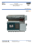
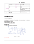
User’s Manual TDLS200 Tunable Diode Laser Spectroscopy Analyzer Start-up Manual IM11Y01B01-11E-A Yokogawa Corporation of America Yokogawa Corporation of America 2 Dart Road, Newnan, Georgia U.S.A. 30265 Tel: 1-800-258-2552 Fax: 1-770-254-0928 IM11Y01B01-11E-A 5th Edition Blank Page IM 11Y01B02-11E-A 5th Edition :June 5, 2012-00 i Introduction Thank you for purchase the TDLS200 Tunable Diode Laser Analyzer. Please read the following respective documents before installing and using the TDLS200. Notes on Handling User’s Manuals • • • • This manual should be passed on to the end user. The contents of this manual are subject to change without prior notice. The contents of this manual shall not be reproduced or copied, in part or in whole, without permission. This manual explains the functions contained in this product, but does not warrant that they are suitable for the particular purpose of the user. • Every effort has been made to ensure accuracy in the preparation of this manual. However, when you realize mistaken expressions or omissions, please contact the nearest Yokogawa Electric representative or sales office. • This manual does not cover the special specifications. This manual may be left unchanged on any change of specification, construction or parts when the change does not affect the functions or performance of the product. • If the product is not used in a manner specified in this manual, the safety of this product may be impaired. Yokogawa is not responsible for damage to the instrument, poor performance of the instrument or losses |resulting from such, if the problems are caused by: • • • • Improper operation by the user. Use of the instrument in improper applications Use of the instrument in an improper environment or improper utility program Repair or modification of the related instrument by an engineer not authorized by Yokogawa. Drawing Conventions Some drawings may be partially emphasized, simplified, or omitted, for the convenience of description. Some screen images depicted in the user’s manual may have different display positions or character types (e.g., the upper / lower case). Also note that some of the images contained in this user’s manual are display examples. Media No. IM 11Y01B01-11E-A 5th Edition :June. 2012 (YCA) All Rights Reserved Copyright © 2012, Yokogawa Corporation of America IM 11Y01B01-11E-A 5th Edition :June 5, 2012-00 ii Safety Precautions Safety, Protection, and Modification of the Product • In order to protect the system controlled by the product and the product itself and ensure safe operation, observe the safety precautions described in this user’s manual. We assume no liability for safety if users fail to observe these instructions when operating the product. • If this instrument is used in a manner not specified in this user’s manual, the protection provided by this instrument may be impaired. • If any protection or safety circuit is required for the system controlled by the product or for the product itself, prepare it separately. • Be sure to use the spare parts approved by Yokogawa Electric Corporation (hereafter simply referred to as YOKOGAWA) when replacing parts or consumables. • Modification of the product is strictly prohibited. • The following safety symbols are used on the product as well as in this manual. DANGER This symbol indicates that an operator must follow the instructions laid out in this manual in order to avoid the risks, for the human body, of injury, electric shock, or fatalities. The manual describes what special care the operator must take to avoid such risks. WARNING This symbol indicates that the operator must refer to the instructions in this manual in order to prevent the instrument (hardware) or software from being damaged, or a system failure from occurring. CAUTION This symbol gives information essential for understanding the operations and functions. Note! This symbol indicates information that complements the present topic. This symbol indicates Protective Ground Terminal " # Warning and Disclaimer The product is provided on an “as is” basis. YOKOGAWA shall have neither liability nor responsibility to any person or entity with respect to any direct or indirect loss or damage arising from using the product or any defect of the product that YOKOGAWA cannot predict in advance. IM 11Y01B02-11E-A 5th Edition :June 5, 2012-00 iii TDLS200 CAUTION SAFETY should be considered first and foremost importance when working on the equipment described in this manual. All persons using this manual in conjunction with the equipment must evaluate all aspects of the task for potential risks, hazards and dangerous situations that may exist or potentially exist. Please take appropriate action to prevent ALL POTENTIAL ACCIDENTS. AVOID SHOCK AND IMPACT TO THE ANALYZER THE LASERS CAN BE PERMANENTLY DAMAGED Laser Safety & Classification according to FDA Regulations. The TDLS200 is Registered with the United States FDA as a Laser Product. WARNING THIS ANALYZER CONTAINS A LASER PRODUCT THAT IS GENERALLY IN ACCORDANCE WITH THE REGULATIONS FOR THE ADMINISTRATION AND ENFORCEMENT OF THE RADIATION CONTROL FOR HEALTH AND SAFETY ACT OF 1968 (TITLE 21, CODE OF FEDERAL REGULATIONS, SUBCHAPTER J). REFER SECTION 1002.10 OF THE REGULATIONS REFERENCED ABOVE. CAUTION INVISIBLE LASER RADIATION AVOID DIRECT EXPOSURE MAXIMUM OUTPUT POWER < 1 MW (Oxygen) MAXIMUM OUTPUT POWER < 20 mW (other Gases) DURING NORMAL OPERATION THIS ANALYZER IS: CLASS I LASER PRODUCT (according to IEC 60825-1) CAUTION The Instrument is packed carefully with shock absorbing materials, nevertheless, the instrument may be damaged or broken if subjected to strong shock, such as if the instrument is dropped. Handle with care. Warranty and service Yokogawa products and parts are guaranteed free from defects in workmanship and material under normal use and service for a period of (typically) 12 months from the date of shipment from the manufacturer. Individual sales organizations can deviate from the typical warranty period, and the conditions of sale relating to the original purchase order should be consulted. Damage caused by wear and tear, inadequate maintenance, corrosion, or by the effects of chemical processes are excluded from this warranty coverage. In the event of warranty claim, the defective goods should be sent (freight paid) to the service department of the relevant sales organization for repair or replacement (at Yokogawa discretion). The following information must be included in the letter accompanying the returned goods: • • • • • • • • Part number, model code and serial Number Original purchase order and date Length of time in service and a description of the process Description of the fault, and the circumstances of failure Process/environmental conditions that may be related to the failure of the device. A statement whether warranty or nonwarranty service is requested Complete shipping and billing instructions for return of material, plus the name and phone number of a contact person who can be reached for further information. Returned goods that have been in contact with process fluids must be decontaminated/ disinfected before shipment. Goods should carry a certificate to this effect, for the health and safety of our employees. Material safety data sheets should also be included for all components of the processes to which the equipment has been exposed. IM 11Y01B02-11E-A 5th Edition :June 5, 2012-00 iv DANGER Dont install “general purpose type” instruments in the hazardous area. CAUTION The intrument is packed carefully with shock absorbing materials, nevertheless, the instrument may be damaged or broken if subjected to strong shock, such as if the instrument is dropped. Handle with care. IM 11Y01B02-11E-A 5th Edition :June 5, 2012-00 TOC-1 Model TDLS200 Tunable Diode Laser Spectroscopy Analyzer Start-up Manual IM 11Y01B01-11E-A 5th Edition CONTENTS Introduction .......................................................................................................................................................... i Safety Precutions ............................................................................................................................................... ii 1 Instrument Check ......................................................................................................................................1-1 2 Quick Start ................................................................................................................................................2-1 3 Installation and Wiring .............................................................................................................................3-1 3.1 Process Measurement Point Considerations .....................................................................................3-1 3.2 Position of Process Flanges for Launch and Detect Units .................................................................3-2 3.3 Process Flange Welding Alignment and Line-Up ...............................................................................3-4 3.4 Process Flange Clear Aperture...........................................................................................................3-5 3.5 Mounting the Launch and Detect Units to the Process Flange .........................................................3-5 3.5.1 Process Window Purge Gas Connection .....................................................................................3-6 3.6 Mounting the Process Interface .........................................................................................................3-6 3.7 Typical Purge Gas Configuration, In-Situ ...........................................................................................3-7 3.8 Typical Purge Gas Configuration, Extractive trace ppm H2O system.................................................3-7 3.9 Dimensional Drawings ........................................................................................................................3-8 3.10 Wiring Drawings ...............................................................................................................................3-15 3.11 Hazardous Area Systems .................................................................................................................3-19 3.11.1 Purging Analyzer for Hazardous Areas (with On-Line Validation) ..............................................3-20 3.11.2 Purging Analyzer for Hazardous Areas (without On-Line Validation) ..........................................3-20 3.11.3 Purging Analyzer and Universal Power Supply and/or URD for Hazardous Areas (with On-Line Validation).............................................................................................................3-21 3.11.4 Purging Analyzer and Universal Power Supply and/or URD (not using On-Line Validation) ......3-21 3.12 Cyclops Division 2/ zone 2 Purge Indicator, with Switch .................................................................3-22 Revison Record .................................................................................................................................................... i IM 11Y01B02-11E-A 5th Edition :June 5, 2012-00 <1 INSTRUMENT CHECK> 1-1 1 INSTRUMENT CHECK Upon delivery, unpack the instrument carefully and inspect it to ensure that it was not damaged during shipment. If damage is found, retain the original packing materials (including the outer box) and then immediately notify the carrier and the relevant Yokogawa sales office. Make sure the model number on the nameplate of the instrument agrees with your order. The nameplate will also contain the serial number and any relevant certification marks. Be sure to apply correct power to the unit, as detailed on the nameplate. For products used within the European Community or other countries requiring the CE mark and/or ATEX classification, the following labels are attached (as appropriate): For Zone 2 (CAT 3) ATEX use the following labels will be attached as appropriate: IM 11Y01B02-11E-A 5th Edition :June 5, 2012-00 <1 INSTRUMENT CHECK> 1-2 For YR-200 (Remote Interface Unit, RIU) Zone 2 (CAT 3) ATEX use the following labels will be attached as appropriate: CAUTION - For Cleaning of the labels and LCD window, please use wet cloth to avoid electrostatic condition. NOTE - ATEX Hazardous Area Operation: Product MUST NOT be used in Zone 0 (CAT 1) locations Product MUST NOT be used in Group I (Dust/Grain) locations Product MUST NOT be used in Group III (Fibers) locations Conditions of Certification On loss off purge an alarm shell be made to inform the user, action shall then be taken by the user to ensure continued use is safe. A functional test shall be carried out in accordance with clause 17.1 of EN 60079-2:2007 to verify the parameters of the Purge Control Unit when fitted. A leakage test shall be carried out in accordance with clause 17.2 of EN 60079-2:2007. The manufacturer shall record and retain these results. Only Lithium batteries specified in manual are to be used in this enclosure. Special Conditions of Certification: A suitability certified Purge Control Unit must be sued with the TDLS Analyzer that is capable providing the requirements listed on label/certificate and that either provides a suitable exhaust through a particle barrier of to a safe area. When installed there shall be a minimum of two pressure regulators in the air/nitrogen supply line. IM 11Y01B02-11E-A 5th Edition :June 5, 2012-00 <1 INSTRUMENT CHECK> 1-3 Materials of Construction The analyzer incorporates a variety of materials in its construction and they should therefore be used in an appropriate manner. Any chemicals (liquid or gas) that may have a detrimental effect on the product’s structural integrity should not be allowed come in contact. The electronic enclosures are constructed from Aluminum Alloy AL Si 12 (ASTM A413) and have a protective epoxy powder coated surface finish. The welded bodies are constructed of stainless steel grade 316 The fasteners are constructed of stainless steel grade 18-8 The windows (when fitted) are constructed of laminated safety glass Maintenance Work by Qualified Personnel Unqualified work on the product may result in severe personal injury and/or extensive damage to property. If the Warnings contained herein are not adhered to the result may also be severe personal injury and/or extensive damage to property. This product is designed such that maintenance work must be carried out by trained personnel. Trained personnel are considered as below: - Engineers familiar with the safety approaches of process analytical instrumentation (and/or general automation technology) and who have read and understood the content of this User Guide. - Trained start-up/commissioning analyzer technicians who have read and understood the content of this Instruction Manual. WARNING – Battery replacement Replacement Battery Installation (Type CR2032 located on CPU). The battery MUST be factory installed and cannot be installed by others at site (soldered connections, required) – Contact factory for further assistance IM 11Y01B02-11E-A 5th Edition :June 5, 2012-00 <2 QUICK START> 2-1 2 QUCIK START Step Title Description 1.0 Preparation Carefully un-pack and check equipment for any obvious damage. This includes flanges, Cables, Power Supplies, manuals and any other supplied options. NOTES: There are 14 ferrules in the accessory bag for tubing-piping. The number of ferrule that are required for actual tubing-piping are different by application. Please see tubing-piping figure specific to project for exact detail. 1.1 Ensure the process connections match the supplied process interface. 1.2 Ensure the appropriate utilities are available and ready for connection. These may include electrical power, nitrogen purge gas, instrument air, validation gas, etc. 1.3 Ensure you comply with any local and/or site specific safety requirements. 1.4 Read the appropriate sections of the Instruction Manual BEFORE starting any installation work – Contact Yokogawa Laser Analysis Division or Local Agent if any doubts! 2.0 Installation 2.1 If separate process isolation flanges have been provided for corrosive service, then install to the process/stack flange/isolation valves. Attach the process interface (alignment flanges) to the site installed flanges (or isolation valves as appropriate). If installing Large Aperture Optics, ensure the detect system is correctly mounted and purged to prevent damage to the large optical element. 2.2 Carefully mount the Launch and Detect Units to their alignment flanges using the quick connect coupling. 2.3 Mount optional equipment such as Universal Power Supply (UPS), Universal Remote Display (URD), Remote Interface Unit (RIU), etc. 2.4 Ambient Temperature The analyzer and some accessories (such as LAO, RIU, UPS, URD, alignment flanges, etc.) are suitable for -20 to +50oC ambient operating temperature. Accessories and Options are available to increase these the operating conditions – please consult Yokogawa for further details. 3.0 Wiring Ensure that all wiring will enable the analyzer launch and detect units to be freely moved from their process location to an adjacent off-line calibration cell. This will entail the use of tray rated cables and/ or flexible conduit and/or other suitable armored cable. Rigid conduit systems are not recommended. 3.1 Connect the appropriate electrical power supply. • 24 VDC to TB1 on the analyzer (launch Unit) backplane. Check that the actual voltage is >23.5VDC otherwise the SBC and other devices will not function! • 110/240 50/60 Hz to UPS or URD, then take 24 VDC to analyzer 3.2 Connect the Launch to Detect interconnect cable (supplied with analyzer) according to the supplied wiring detail (TB7 on the Launch and TB 13 on the Detect Unit). 3.3 Connect any analog I/O signals to the analog I/O Board. Outputs land on TB8 and Inputs land on TB9. 3.4 Connect any other equipment such as URD, Ethernet, solenoid valves, digital I/O, etc. 3.5 Check terminations and ensure all cable shields are landed per supplied wiring details. 4.0 Utilities NOTE! – All purge, Validation Gas and other gas utility lines should be thoroughly cleaned, dried and purged prior to connecting to the analyzer – Failure to do so can result in serious damage to the TDLS200 or contamination to the internal optical elements. Connect the appropriate analyzer purge gas (nitrogen for oxygen analyzers) and make site connections per the supplied purge gas sequence details (including any Hazardous area purge system). Start the purge gas flow accordingly. ATEX purge requires dual regulators at the inlet purge gas supply to prevent overpressure damage in the event of a single regulator failure! 4.1 Connect the appropriate process window purge gas (nitrogen for oxygen analyzers) and make site connections per the supplied purge gas sequence details. Start the window purge gas flow accordingly – ensuring that any isolation valves are open. 4.2 Connect the appropriate analyzer on-line check gas flow cell gas (nitrogen for oxygen analyzers) and make site connections per the supplied purge gas sequence details. Start the purge gas flow accordingly. 4.3 Connect and check any other required utility connections (such as steam trace for heated isolation flanges or flow cells) or secondary window purges for lethal service gases. Start other utilities accordingly. IM 11Y01B02-11E-A 5th Edition :June 5, 2012-00 <2 QUICK START> 2-2 Leak-check all connections and ensure pressure ratings are not exceeded! 4.4 5.0 Power-Up Apply power to the analyzer and using a multi-meter, check for 24VDC power at TB1 on the launch unit back plane. 5.1 Use the internal On-Off switch to power-up the analyzer. 5.2 Observe the various LED clusters on the backplane and FPGA boards. All blue LEDs located on the lower right side of the back-plane should be on. 5.3 Observe the Green power indicator on the SBC. 5.4 Observe the LEDs on the analog I/O board. 6.0 Checking If there is an installed optional 6.5” Display and Keypad – Observe the Main Menu messages and status information. 6.1 If there is an installed optional Mini Display (4x20 VFD) – Observe the status line message. 6.2 If there is no installed User Interface, then connect a laptop PC via Ethernet to the SBC mounted on the backplane. Initiate the supplied VNC software from the laptop to initiate a VNC session with the ‘blind’ analyzer and observe the analyzer Main Menu via the laptop. At this time there may be one or more alarm message due to low transmission, out of range parameters or other – final system configuration is still required! Please also note that the analyzer laser temperature control is disabled for the initializing period (5 minutes) – this means that even manual control of the laser temperature is disabled during this period. 6.3 Alignment Initially, observe the Transmission value through the appropriate user interface. The objective is to adjust alignment until the maximum transmission value is obtained. Perfect alignment in a clear process gas will yield close to 100% transmission. If the analyzer displays a Warning “Validation Required”, this indicates there is no target gas absorption peak found at start-up. Introduce some measured gas into the optical path and re-start or perform a validation with target gas. This will ensure that the analyzer is correctly tuned to the measurement gas absorption peak. If this Warning cannot be cleared by either method, please contact Yokogawa Laser Analysis Division or your local agent for further assistance. If you have 100% certainty that the analyzer is already measuring the process gas and validation is not currently possible then, this alarm can be cleared via the Advanced Calibrate & Validate menu. 7.0 Alignment – check Initially, observe the Transmission value through the appropriate user interface. The objective is to adjust alignment until the maximum transmission value is obtained. Perfect alignment a clear process gas will yield close to 100% transmission. 7.1 Start by adjusting the Launch unit alignment flange nuts up-down and left right. Look for increases and decreases in transmission strength to aid in the alignment. 7.2 When it has been maximized at the launch side, adjust the detect unit accordingly. 7.3 Further adjustment can be made by maximizing the raw detector voltage signal (available at test points on both launch and detect). The signal should be maximized and will not exceed 5.3V DC for low temperature (<600C process) or 9.9V DC for high temperature (>600C process). 7.4 Detector Gain For Large Aperture Optics (LAO) systems, please refer to the Detector Gain Adjustment section of this User Guide to ensure correct functionality and adjustment. 8.0 Configure BASIC By way of the appropriate user interface, the correct process parameters and other parameters can now be entered. 8.1 Enter the Basic Menu and go to Configure. 8.2 Optical Path Enter in the correct optical path length. 8.3 Gas Pressure Enter in the correct process gas pressure (if Active, see Advanced Configure). 8.4 Gas Temperature Enter in the correct process gas temperature (if Active, see Advanced Configure). 8.5 If any other parameters are required to be set (such as analog I/O ranges, alarms levels, Auto Validation sequences) then the Advanced Menu needs to be accessed. Advanced Menu access is Password protected and should only be used by skilled and trained persons - Contact Yokogawa Laser Analysis Division or Local Agent if any doubts! IM 11Y01B02-11E-A 5th Edition :June 5, 2012-00 <2 QUICK START> 2-3 9.0 Configure ADVANCED 9.1 Using the correct password (Default 1234), enter in to the Advanced Menu, then the Configure. Select the desired measurement units (English or Metric selected on an individual parameter basis). 9.2 Optical Path Enter in the correct optical path length. 9.3 Gas Pressure Select Fixed or Active. If Fixed, enter in the correct process gas pressure. If Active, enter in the 4-20mA input signal range proportional to the pressure range. “Control” mode is not applicable to TDLS200 9.4 Gas Temperature Select Fixed or Active. If Fixed, enter in the correct process gas temperature. If Active, enter in the 4-20mA input signal range proportional to the temperature range. Active ambient and Active Peaks may also be used, refer to project specific and application specific details. “Control” mode is not applicable to TDLS200 9.5 Configure the system I/O by entering in to the System I/O sub menu in Configure. 9.6 If the Analog I/O board is installed, then select Analog Output and set the appropriate 4mA and 20mA values for Ch1 Concentration and Ch2 Transmission. 9.7 Select what mode (Block, Track or Hold) the 4-20mA outputs are to be when the analyzer is in Warning, Fault and Calibration Modes. 9.8 Configure Digital outputs – Warnings and Faults. Many of these will be factory preset so if unsure about any settings then leave as Factory Default. Select and set level for Alarm Limit to either the Measured Gas orTransmission. 9.9 Go to the Data screen and set the appropriate parameters for and ‘Spectrum Capture’. These will ensure the analyzer stores important information during operation that may be used to verify operation/status/diagnostics and other trouble shooting. 9.10 Go to the Trends screen and review/plot several of the listed parameters to check analyzer performance over a period of time. 9.11 Non- Process Parameters If the application use gas containing the target gas (e.g. Oxygen measurement with Instrument Air Purge) then the Non-Process parameters should be configured as detailed later in this manual under the Software Section. Non-Process Parameters should also be configured if using a linelocking gas in the validation cell (e.g. CO for combustion). 10.0 Normal Operation When the site/field configuration is complete and the analyzer has operated for at least two hours without any functional alarms, then perform an export data routine. 10.1 To Export Data, simply insert an empty USB memory stick in to a USB port on the launch unit back plane. The data transfer may take several minutes. DO NOT REMOVE THE MEMORY STICK DURING THIS TIME! 10.2 Close out the VNC software and disconnect the service PC – if connected. 10.3 Ensure the doors/lids are closed and tightly sealed. 10.4 The system is now in normal operation mode. 10.5 We RECOMMEND sending all the Exported Data files to Yokogawa Laser Analysis Division along with any notes and comments. We will then be able to store these files on a master record for future reference. Please carefully read the appropriate Sections of this Instruction Manual. The TDLS200 Tunable Diode Laser (TDL) Analyzer is a technologically advanced instrument that requires the appropriate care when handling, installing and operating. Failure to do so may result in damage and can void any warranties! If there is any doubt about any aspect of the Instrument or its use, please contact Yokogawa Laser Analysis Division and/or your authorized Representative/Distributor. IM 11Y01B02-11E-A 5th Edition :June 5, 2012-00 <3 INSTALLATION AND WIRING> 3-1 3 INSTALLATION AND WIRING Detailed Installation, Wiring, Utility Drawings are included on a Project Basis. Please contact Yokogawa for any project specific documentation to ensure correct installation. Drawings provided herein are considered for standard installation use only 3.1 Process Measurement Point Considerations The following criteria should be considered when selecting the installation point in respect to the process conditions: • Process Gas Flow Conditions – Laminar, homogenous gas concentration distribution conditions across the measurement point are recommended. For circular ducts/stacks this condition is generally at least three unimpaired diameters (D) before and after a process bend. For rectangular cross sections, the hydraulic ductdiameter (D) is derived from: D = (4 x duct cross sectional area) / duct circumference If neither situation exists or is possible, then distribution of the unimpaired section of duct should be 66% on the inlet side and 34% on the outlet side. Profiling of the proposed measurement point may be required to ensure that a correct installation point is selected. • Process Gas Temperature – It is recommended that the analyzer be installed at a location where temperature fluctuations are minimized. Generally as a guide, if the temperature of the gas at the point where the analyzer is to be installed is to vary by more than +/-10˚C (+/-18˚F) then an “Active” input signal should be used for compensation. Ensure the analyzer has been selected and configured to suit the maximum operating gas temperature. Lower gas temperatures generally lead to better measurements. • Process Gas Pressure – It is recommended that the analyzer be installed at a location where pressure fluctuations are minimized. Generally as a guide, if the pressure of the gas at the point where the analyzer is to be installed is to vary by more than +/- 0.05 Bar (+/- 0.725 psi) then an “Active” input signal should be used for compensation. Ensure the analyzer has been selected and configured to suit the maximum operating gas pressure. Ensure the process isolation windows have been selected and configured to suite the maximum design gas pressure. Lower gas pressures generally lead to better measurements. • Process Dust/Particulate Matter – It is recommended that the analyzer be installed at a location where dust loadings are minimized. Dust and other particulate matter will reduce the optical transmission of the measuring laser beam. Within limits, the loss of optical transmission does not effect the measurement however a Warning alarm will be initiated when the transmission falls below allowable limits. The amount of dust loading is also dependant upon the optical path length – Consult Factory for further details. Lower dust loads generally lead to better measurements. IM 11Y01B02-11E-A 5th Edition :June 5, 2012-00 <3 INSTALLATION AND WIRING> 3-2 3.2 Position of Process Flanges for Launch and Detect Units: Process flanges should be located on the process such that the Launch and Detect Units can be installed, accessed and removed in a safe and convenient manner. The following criteria/Check List should be met at a minimum: • • • • • • • • • • • • Good, Safe Engineering practices Local codes and regulations for such equipment installation Appropriate hazardous area (if applicable) precautions Owner Company best practice and engineering standards Access for personnel to stand in front of launch and Detect Units Clearance for installation and removal of Launch and Detect (see below) Clearance for installation and removal of purge insertion tubes (if applicable) Access to process isolation valves Safe routing for interconnecting cables Ambient conditions in accordance with analyzer limits Access to appropriate utilities Adjacent space for mounting to Calibration Cell when off-line Figure 22 - and Detect Unit – In-Situ Installation Overview Figure 1 - Launch and Detect Unit-In -Situ Installation Overview Figure 2 - Launch and Detect Unit-In-Situ with Insertion Purge Tube Installation Overview IM 11Y01B02-11E-A 5th Edition :June 5, 2012-00 <3 INSTALLATION AND WIRING> 3-3 Figure 3 - Launch or Detect Unit Installation Dimensions The standard flange sizes are either 2” or 3” 150# R.F. ANSI as well as DN50 and DN80. Please check the exact flange size specified and provided for the particular installation. Other flange sizes and a variety of materials (to suit the process) are available so please check these details prior to installing the flanges on the process. Note: The process isolation valves should have at least a 1½” (38mm) diameter clear bore size (aperture) to ensure there is sufficient tolerance to align the laser beam after installation. Ducts and Stacks that have thin and flexible walls should be reinforced to ensure that the laser beam alignment is maintained at all times. Rigid mounting for the process flanges is highly recommended to ensure a lignment is maintained. In situations where the process flanges are mounted to these thin and flexible duct/stack walls, a larger reinforcing plate should be welded around the mounting flange area to increase the attaching region. The figure below depicts a typical suggestion however; it is the installer’s responsibility to ensure appropriately rigid installation is provided for the analyzer. Figure 4 - Suggested Reinforcing Plate for Launch or Detect Unit Flanges- reduce flexing with mechnical reinforcement to duck/stack walls IM 11Y01B02-11E-A 5th Edition :June 5, 2012-00 <3 INSTALLATION AND WIRING> 3-4 3.3 Process Flange Welding Alignment and Line-Up The Launch and Detect units are provided with alignment mechanisms that allow for some manual adjustment of the laser beam direction in both planes. It is however recommended that the following angular tolerances be adhered to as closely as possible. PROCESS FLANGE ANGULAR TOLERANCE Angular tolerance PROCESS FLANGE BOLT ALIGNMENT NOZZLE FLANGE BOLT PATTERN MUST BE AS INDICATED TO ASSURE PROPER MOUNTING OF ANALYZER LAUNCH AND DETECT UNITS COMBINED ANGULAR OFFSET OF BOTH NOZZLES MUST NOT EXCEED 2” IN ANY DIRECTION. BEST INSTALLATION WILL HAVE NO ANGULAR OFFSET Figure 5 - Angular Alignment Tolerances for Launch or Detect Unit Flanges IM 11Y01B02-11E-A 5th Edition :June 5, 2012-00 <3 INSTALLATION AND WIRING> 3-5 3.4 Process Flange Clear Aperture The Launch and Detect unit flanges (and insertion tubes if used) should be installed in such a way that a minimum clear through aperture (opening) diameter of 1 ½” (38 mm) when the distance between the 2” 150# flange faces does not exceed 6ft (~2 m). Note: Larger clear through apertures may be required when operating over longer distances – CONSULT FACTORY for further details. PROCESS FLANGE CLEAR APERTURE TOLERANCE LATERAL OFFSET OF NOZZELS MUST BE MINIZED AS TO ALLOW FOR MINMUM 1.75” [45MM] CLEAR APERTURE. BEST INSTALLATION WILL HAVE NO LATEAL OFFSET. Figure 6 - Clear Aperture for Launch or Detect Unit Flanges 3.5 Mounting the Launch and Detect Units to the Process Flange Securely bolt the Launch and Detect Units to the process flanges using the standard bolt holes provided. Ensure the correct size bolts, nuts, and gasket are used in accordance with the flange specifications and in accordance with the process specifications when applicable. NOTE: If the process isolation valve flange is excessively hot due to the process temperature or radiant heat, then a thermal insolating flange gasket should be used in order to minimize the heat transfer to the analyzer flange face. It is generally beneficial to make the flange of the Launch and Detect Units and the flange of the process concentric with each other. Due to the large clearance provided by standard flanges and bolts, it is possible to mount the two flanges in an un-concentric manner – this should be avoided to aid laser beam alignment. IM 11Y01B02-11E-A 5th Edition :June 5, 2012-00 <3 INSTALLATION AND WIRING> 3-6 3.5.1 Process Window Purge Gas Connection In order to keep the process windows clean (prevent fouling by process gas) it is necessary to purge the windows with a clean dry gas of sufficiently low dew point. When measuring Oxygen, Nitrogen should be used for purging the windows. The purge gas or nitrogen should be clean (<0.5 μ particulate), dry (-40˚C dew point), oil free. The process flanges are provided with two diagonally opposed inlet ports (typically ¼” OD tube). Use Swagelok (or equal) double ferrule tube fittings and connect both ports with ¼” OD stainless steel tubing to the purge gas supply. The exact purge gas flow rate will be dependant upon the process conditions that exist at the flange connection and therefore, the flow rate could be anywhere from 5lts/min to 50lts/min (~10 SCFH to ~100 SCFH). Ensure the purge gas line is clean and dry prior to connecting to the flange to ensure any condensate or debris is not blown on to the windows at initial start-up. The same applies to both Launch Unit and Detect Unit process flanges, with and without any insertion purge tubes installed. 3.6 Mounting the Process Interface – standard 2”, 3”. 4” 150# ANSI RF or DN - 50/80 Alignment Studs (x4) Analyzer Mounting Flange Alignment Nuts (x8) Process Flange Window Purge Port (x2) Analyzer Quick Connect Alignment Bellows Figure 7 3” 150# Welded Metal Bellows Alignment Flange Shown above, with analyzer quick connect IM 11Y01B02-11E-A 5th Edition :June 5, 2012-00 <3 INSTALLATION AND WIRING> 3-7 3.7 Typical Purge Gas Configuration, In-Situ Please refer to project specific details, the following is a typical standard in-situ configuration: Figure 8 3.8 Typical Purge Gas Configuration, Extractive trace ppm H2O system: Please refer to project specific details, the following is a typical standard enhanced flow cell configuration: Figure 9 IM 11Y01B02-11E-A 5th Edition :June 5, 2012-00 <3 INSTALLATION AND WIRING> 3-8 Typical Purge Large Aperture Optics (LAO) combustion O2, CO/CH4 Figure 10 3.9 Dimensional Drawings Figure 11 - General Installation Clearance Requirements IM 11Y01B02-11E-A 5th Edition :June 5, 2012-00 <3 INSTALLATION AND WIRING> 3-9 Figure 12 -Off-Line Calibration Overview Figure 13 - Launch and Detect unit Dimensions IM 11Y01B02-11E-A 5th Edition :June 5, 2012-00 <3 INSTALLATION AND WIRING> 3-10 Figure 14 - Remote Interface Unit Figure 15 - Universal remote Display (URD) IM 11Y01B02-11E-A 5th Edition :June 5, 2012-00 <3 INSTALLATION AND WIRING> 3-11 Figure 16 - Universal Power Supply (UPS) Figure 17 - Alignment Bellows * Other flange sizes available to meet application needs IM 11Y01B02-11E-A 5th Edition :June 5, 2012-00 <3 INSTALLATION AND WIRING> 3-12 Figure 18 - Large Apenture * Other flange sizes available to meet application needs Figure 19 - Isolation Flanges, model IF200 IM 11Y01B02-11E-A 5th Edition :June 5, 2012-00 <3 INSTALLATION AND WIRING> 3-13 Figure 20 - Insertion Tube Detail Figure 21 - Off-Line Calibration Gas and Purge Detail IM 11Y01B02-11E-A 5th Edition :June 5, 2012-00 <3 INSTALLATION AND WIRING> 3-14 Figure 22 - Utility Panel Tubing Detail Standard Single, Auto - validation Figure 23 - Utility Panel Tubing Detail Standard Dual Auto - validation IM 11Y01B02-11E-A 5th Edition :June 5, 2012-00 <3 INSTALLATION AND WIRING> 3-15 3.10 Wiring 3.10.1 Wiring of Launch for the US version Figure 24 IM 11Y01B02-11E-A 5th Edition :June 5, 2012-00 <3 INSTALLATION AND WIRING> 3-16 3.10.2 Launch and Detect Unit Wiring – Standard for CE/ATEX SPECIAL NOTE: Noise sources magnetically coupled to the 4-pair launch to detect cable can cause errors to the measurement if the frequency and applied total voltage meet or exceed the following; Frequency range of 0.1 to 7.5 MHz and Total induced voltage of 3Vrms. A combination of these parameters will cause measurement error outside of the analyzer performance specification. In practice, these potential errors can be easily avoided by routing the 4-pair launch to detect cable away from electromagnetic interference sources that could exhibit these parameters. Such sources might include power transformers, electric motors, electric welding machinery, high voltage power lines, etc. Analyzer grounding wires and any other I/O lines such as 8-pair launch to utility panel cable or A I/O cables to/from the DCS should also be installed with similar basic practices to also ensure there is no additional adverse influence on any of the I/O signals. Launch Unit (to Detect) Terminations TB-7 (ensure 360˚ cable shield ground) Detect Unit (to Launch) Terminations TB-7 (ensure 360˚ cable shield ground) IM 11Y01B02-11E-A 5th Edition :June 5, 2012-00 <3 INSTALLATION AND WIRING> 3-17 Launch and Detect Unit Wiring – Standard GP/Div2 (non CE/ATEX) Launch Unit (to Detect) Terminations at TB-7 Detect Unit (to Launch) Terminations at TB-13 IM 11Y01B02-11E-A 5th Edition :June 5, 2012-00 <3 INSTALLATION AND WIRING> 3-18 3.10.3 Launch Unit Terminations CE/ATEX/GP/Div2 – all units: SEE FOLLOWING NOTES: Please NOTE that ALL analog output signals from TB-8 are POWERED BY THE ANALYER! Outputs from TB-9 can be configured for POWERED inputs or LOOP POWERED external transmitter! PLEASE CHECK CAREFULLY BEFORE APPLYING POWER TO THE ANALYZER! IM 11Y01B02-11E-A 5th Edition :June 5, 2012-00 <3 INSTALLATION AND WIRING> 3-19 3.11 Hazardous Area Systems The TDLS200 Analyzer requires a continuous nitrogen or I/A gas purge to prevent ambient oxygen ingress to the optical path, when oxygen is the measured gas. The flow rate can be minimized as long as it prevents any ambient oxygen ingress to the measurement optical path. Other purge gases may be used as long as they do not contain any of the measured gas and are clean, dry, etc. If using a purge gas that also contains the measured gas (e.g. purge with instrument air and measuring process/combustion oxygen) then the Non-Process Parameters software feature/parameters will have to be implemented. For hazardous area operation, the same nitrogen purge gas is used to purge the entire analyzer (including non-optical path sections such as the electronics). The process interface may also require purging to maintain clear windows, refer to Process Window Purge details separately. NOTE: Please also refer to any separate Purge System Original Manufacturers Operating Instructions and Manuals in conjunction with this User Guide. The Purge Systems are not manufactured by Yokogawa Laser Analysis Division. Please also refer to separate detailed manufacturer’s instructions and start-up information for any Zone 1 or Division 1 automatic purge controller unit operational details. Failure to follow the manufacturer’s guideline can result in damages and/or non-functionality of the purging system! IM 11Y01B02-11E-A 5th Edition :June 5, 2012-00 <3 INSTALLATION AND WIRING> 3-20 3.11.1 Purging Analyzer for Hazardous Areas (with On-Line Validation) • • NEC/CSA Class 1, Division 2, Groups A-D ATEX Zone 2 CAT 3 Dual regulators must be used on the inlet! The block diagram below shows the sections of the analyzer that require nitrogen purging. A Z-Type purge control system is fitted the Launch Unit and it includes a local indicator (Bright Green, rugged light) and pressure switch alarm contacts (open on loss of purge pressure). The purging should be carried in sequence typically as shown below. All purge gas connections are ¼” od Tube fittings. Laser Module Check Gas Flow Cell Process Interface Main Main Electric Electronic Housing Housing& &Purge Purge System Process Interface Nitrogen or or I/A I/A Purge Nitrogen Purge Gas Gas Nitrogen or I/A Purge Gas Detect Module Detect Electronic Detect Electronic Housing Housing Figure 25 - Purge Flow Diagram when using on line validation 3.11.2 Purging Analyzer for Hazardous Areas (without On-Line Validation) • • NEC/CSA Class 1, Division 2, Groups A-D ATEX Zone 2 CAT 3 – Dual regulators must be used on the inlet! The block diagram below shows the sections of the analyzer that require nitrogen purging. A Z-Type purge control system is fitted the Launch Unit and it includes a local indicator (Bright Green, rugged light) and pressure switch alarm contacts (open on loss of purge pressure). Laser Module Check Gas Gas Check Flow Cell Cell Flow Process Interface Main Main Electronic Electric Housing Housing& &Purge Purge System Process Interface Nitrogen or I/A Purge Gas Detect Module Detect Detect Electronic Electronic Housing Housing Figure 26 - Purge Flow Diagram when not using on line validation IM 11Y01B02-11E-A 5th Edition :June 5, 2012-00 <3 INSTALLATION AND WIRING> 3-21 3.11.3 Purging Analyzer and Universal Power Supply and/or URD for Hazardous Areas (with On-Line Validation) • • NEC/CSA Class 1, Division 2, Groups A-D ATEX Zone 2 CAT 3 – Dual regulators must be used on the inlet! The block diagram below shows the sections of the analyzer that require nitrogen purging when using in conjunction with either or the Universal Power Supply and Universal Remote Display. AZ-Type purge control system is fitted the Launch Unit and it includes a local indicator (Bright Green, rugged light) and pressure switch alarm contacts (open on loss of purge pressure). Laser Module CheckGas Gas Check Flow Cell Flow Cell Process Interface Main Electronic Housing & Purge System Nitrogenor orI/A I/APurge Purge Nitrogen Gas Gas Process Interface Nitrogen or I/A Purge Gas Detect Module Detect Detect Electronic Electronic Housing Housing Power Supply or URD Figure 27 - Purge Flow Diagram when using on line validation 3.11.4 Purging Analyzer and Universal Power Supply and/or URD (not using On-Line Validation) • • NEC/CSA Class 1, Division 2, Groups A-D ATEX Zone 2 CAT 3 – Dual regulators must be used on the inlet! The block diagram below shows the sections of the analyzer that require nitrogen purging. A Z-Type purge control system is fitted the Launch Unit and it includes a local indicator (Bright Green, rugged light) and pressure switch alarm contacts (open on loss of purge pressure). The purging should be carried in sequence typically as shown below. All purge gas connections are ¼” od Tube fittings. Laser Module Check Gas Check Gas FlowCell Cell Flow Process Interface Main Main Electronic Electronic Housing & Housing Purge & System Pureg System Process Interface Nitrogen or I/A Purge Gas Detect Module Detect Detect Electronic Electronic Housing Housing Power Power Supply or Supply URD or URD Figure 28 - Purging Analyzer for Hazardous Areas -NO- On-Line Validation IM 11Y01B02-11E-A 5th Edition :June 5, 2012-00 <3 INSTALLATION AND WIRING> 3-22 3.12 Cyclops Division 2/Zone 2 Purge Indictor, with switch Type Z purging reduces the classification within a protected electronics enclosures from Division 2 or Zone 2 to nonhazardous. Failure to maintain pressure within the protected enclosure shall be detected by an alarm or indicator at the electronics enclosure. The dilution purge time shall be a manual operation and once the electronics enclosure has been purged of ignitable or flammable concentrations, only positive pressure of at least 0.20 inches H2O (0.50 mbar) is required to be maintained within the electronics enclosure and it is not necessary to remove power from the protected equipment upon the loss of purge pressure. The CYCLOPS Z – Purge Indicator is used to provide safe monitoring of electrical equipment in Division 2 and Zone 2 hazardous areas, which can be used to prevent the possibility of fire or explosion inside the enclosure of energized electrical equipment, a protective gas supply is used to dilute potentially flammable materials to an acceptable level, creating a safe area for the electrical equipment within the enclosure. Positive pressure prevents the ingress of flammable materials in the surrounding atmosphere from entering into the enclosure, as long as positive pressure is maintained. After the enclosure is purged, power may be manually applied to the protected electrical equipment. The CYCLOPS Z – Purge Indicator provides an objective evidence of the presence of adequate positive purge pressure within the electrical equipment enclosure. A normally open differential pressure switch continuously compares the pressure inside the monitored electronics enclosure with respect to the atmospheric pressure surrounding the electronics enclosure. When the monitored electronics enclosure register’s a pressure of at least 0.20 inches H2O (0.50 mbar) above the reference atmospheric pressure a manually controlled dilution time cycle may then begin. Typically, a minimum dilution time cycle is specified to ensure that at least five times the volume of free space in the electronics enclosure is exchanged before power is manually applied to the electrical equipment. (The number of exchanged volumes may be higher in some situations). After the manual dilution time cycle has elapsed and the monitored electronics enclosure pressure is being maintained above 0.20 inches H2O (0.50 mbar), power may be manually applied to the electrical equipment within the purged electronics enclosure. The CYCLOPS Z – Purge Indicator is designed to indicate the presence of purge pressure from one pressure reference point. Several electronics enclosures can be installed in series with purge gas being introduced into the first electronics enclosure and the CYCLOPS Z – Purge Indicator monitoring the last electronics enclosure in the series; multiple electronics enclosures can now be monitored using only one CYCLOPS Z – Purge Indicator. The pressure inside the monitored electronics enclosures must maintain at least 0.20 inches H2O (0.50 mbar) higher than the atmospheric pressure surrounding the electronics enclosure. This ensures that hazardous materials are not going to ingress into the pressurized and now protected electronics enclosures. If any of the electronics enclosures installed in the series door is opened, pressure will show to be below the required 0.20 inches H2O (0.50 mbar) in all electronics enclosures. The exhaust vent which comes as part of the CYCLOPS Z – Purge Indicator casing, can exhaust purge gas from enclosures with volumes up to 15 cubic feet (425 liters). Cyclops Features Certified for installation and use in ATEX and IECEx for Type Z – Purge, II 3 G Ex nA nL [pz] IIC T6 For Zone 2 gas hazardous areas Certified for installation and use in ATEX and IECEx for Type Z – Purge, II 3 G Ex nA nL [pz] IIC T6 For Zone 2 gas hazardous areas IM 11Y01B02-11E-A 5th Edition :June 5, 2012-00 <3 INSTALLATION AND WIRING> 3-23 Normal Operating Conditions Certified for installation and use in ATEX and IECEx for Type Z – Purge, II 3 G Ex nA nL [pz] IIC T6 For Zone 2 gas hazardous areas Power Manual Dilution Cycle Time To Typically, dilution cycle time is to ensure that at least five (5) Energizing Electrical Equipment times the volume of free space in the enclosure of protective gas supply is exchanged before power is applied to the electrical equipment. Ten (10) times volumes for motors, generators and other rotating electrical machinery. CYCLOPS Z – Purge Indicator, Minimum Pressure Green indicator light remains on to show purge pressure being maintained above 0.20 inches H2O (0.50 mbar) in electronics enclosure being monitored. WARNING: The number of exchanged volumes may be higher in some situations. Refer to TDLS-200 ATEX Purge Warning Labels for Details. NOTE: Instrument Air and Nitrogen purge gases have different purge time requirement. It is important to use clean, dry purge gases to ensure the pressure switch contacts do not foul and cause subsequent operating issues (i.e. non-functionality of the Cyclops). Utility Requirements Purge Protective Gas Supply Pressure to Pressure Regulator 20 psig (1.4 Bar) minimum (Suggested to compensate for enclosure leak rate) Purge Protective Gas Supply Quality Water and oil-free, - 40°F (- 40°C) dew point, particles ≤ 5μ, ISA grade hydrocarbon free Power Input / Consumption 0.5 Watts maximum Voltage CYCLOPS Z – Purge Indicator 4VDC model (19VDC to 28VDC) 47 to 63 Hz Not to Exceed 10% Mains Supply Fluctuation Environmental Conditions Operating Temperature Range - 40°F to 150°F (- 40°C to 65°C) Used and Mounted For Indoor and Outdoor Use Casing Material Specifications Anodized Aluminum Weight 2.48 lbs (1.13 kg) Anodized Aluminum Protection NEMA 4 (IP66) IM 11Y01B02-11E-A 5th Edition :June 5, 2012-00 <REVISION RECORD> i Manual Title: Model TDLS200 Tunable Diode Laser Spectroscopy Analyzer Start-up Manual Manual Number: IM 11Y01B01-11E-A Edition 1st 2nd 3rd 4th 5th Date April 2008 April 2009 April 2010 Remark (s) Newly Published Revisions: Formatting was corrected. Revisions: February 2012 Updated to include latest manual information. Revisions: June 2012 Quick start section 1 was modified. Revisions: 1. Formatting was corrected. 2. Introduction and Safety Precautions pages i-iv were added. 3. Instrument check, now section one was added. 4. Quick Start section changed to section 2. 5. Installation and wiring section 3 was added. 6. Revision Record was added. 7. Back panel for CD holder was added. IM 11Y01B02-11E-A 5th Edition :June 5, 2012-00 Blank Page IM 11Y01B02-11E-A 5th Edition :June 5, 2012-00 TDLS200 TruePeak Series Electronic User’s Manaul IM 11Y01B01-21E-A CD-R [Contents] This CD-ROM contains information in PDF format that is necessary for sale and effective operation of the product. www.yokogawa.com/us WARNING: This CD-ROM contains software, and is for use in a computer only. Do not play this on an audio CD player, as the high volume may damage your hearing or audio speakers. copyright © 2012, Yokogawa Corporatoin of America. All Rights Reserved. Yokogawa Corporation of America North America 2 Dart Road, Newnan, GA 30265-1094, USA Phone: 800-258-2552 Fax: 770-254-0928 12530 West Airport Blvd., Sugar Land, TX 77478 Phone: 281-340-3800 Fax: 281-340-3838 Yokogawa has an extensive sales and distribution network. Please refer to the website (www. yokogawa.com/us) to contact your nearest representative. Mexico Melchor Ocampo 193, Torre C, Oficina 3”B” Veronica Anzures D.F., C.P. 11300 Phone: (55) 5260-0019, (55) 5260-0042 Yokogawa Canada, Inc. Bay 4, 11133 40th Street SE, Calgary, AB Canada T2C2Z4 Phone: 403-258-2681 Fax: 403-258-0182 IM 11Y01B01-11E-A Subject to change without notice Copyright ® 2012 05-1206 (A) I Printed in The USA IM 11Y01B02-11E-A 5th Edition :June 5, 2012-00