1
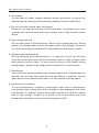
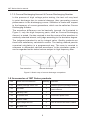
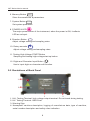
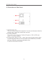
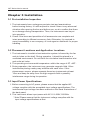
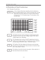
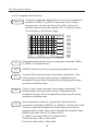
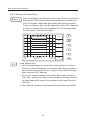
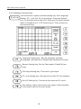
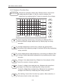
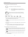
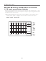
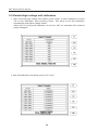
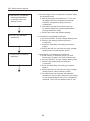
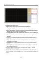
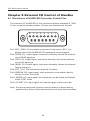
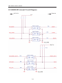
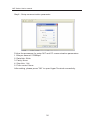
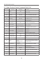
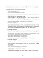
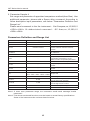
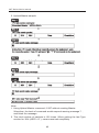
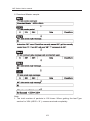
IWT Series User's manual
IWT Series User's manual
Chapter 1 Product Description........................................1
1-1 A Brief Introduction of the Product
1-2 Security and Cautions
1-3 Overview
1-4 Introduction
1-5 Principles of the pulsed coil tester
1-6 Specifications and Features
1-7 Introduction of Comparison Methods
1-7-1 AREA SIZE
1-7-2 DIFFERENTIAL AREA
1-7-3 Corona Discharging Amount & Corona Discharging Number
1-8 Accessories of IWT Series products
Chapter 2 Panel and Display..............................................7
2-1 Illustrations of Front Panel
2-2 Illustrations of Back Panel
2-3 Illustrations of Side Panel
Chapter 3 Installation............................................................10
3-1 Pre-installation Inspection
3-2 Placement Locations and Application Locations
3-3 Input Power Specifications
3-4 Employment of Alternative Fuse
Chapter 4 Functions................................................................11
4-1 Connection proceedings
4-2 Starting-up Frame
4-3 Function Illustrations of Main Frame
4-4 Illustrations of Panel Function keys
IWT Series User's manual
4-4-1 Sample Control Key
4-4-2 Compare Function Key
4-4-3 Auto Function Key
4-4-4 Memory Function Key
4-4-5 System Function Key
4-4-6 Analyzer Function Key
4-4-7 Function Illustrations of the Character Keys
4-4-8 Illustrations of Special Function Key
4-4-9 Illustrations of Power Function Key
Chapter 5 Voltage Calibration Procedure.............22
5-1 The way to execute Voltage Calibration
5-2 Enable High Voltage Calibration
Chapter 6 Operation and Usage...................................25
6-1 Fast Operations
Chapter 7 Connection and Use of PC-LINK........27
7-1 PC-LINK Installation
7-2 PC-LINK Operations
7-3 PC-LINK Software Operations
Chapter 8 External I/O control of
handler................................................................................30
8-1 Illustrations of HANDLER Connector Control Pins
8-2 HANDLER Internal Circuit Diagram
8-3 Sequence Control Procedure
8-4 External Interruption (break)
Chapter 9 RS232 Hyper Terminal Remote
Control Command......................................................34
9-1 Initial Connection Setup
9-2 How to Use Hyper Terminal Testing
9-3 The Hyper Terminal Control Command Quick List
9-4 Upland & Download Transfer Protocol
9-5 Sample of Remote Command
IWT Series User's manual
Chapter 1 Product Description
1-1 A Brief Introduction of the Product
Ever since its foundation in 1980, Leaptronix has dedicated to the services of
IC programming and measurement, aiming to provide the manufacturer with
an integrated R&D environment and high-quality measurement instruments.
With a view to the measurement requirements of various products in the
digital times, our company further cooperate with different industries, and
set up Leaptronix so as to provide the most important analyzers such as
logical analyzer series and passive component analyzer series: the passive
component analyzer series products are represented by IWT Series.
IWT Series, Impulse winding component tester is a coil testing instrument with
self-insulating property, which can be used to test the insulating situations of
coil layers, jumpers and jacks caused by winding materials, magnetic
materials and framework. 200V~5000V programmable pulse voltage setting,
100MHz high-speed sampling rate, non-destructive testing, etc, can detect illinsulating winding components.
1-2 Security and Cautions
All the operations, repair and maintenance services must abide
by the following security precautions. Any unexpected situation caused
by misuse of this instrument due to failure of compliance with the
precautions shall eliminate our responsibilities.
For the safe usage of the instruments, the following precautions should be
strictly observed.
1. Installation environment of this instrument
Please don’t place heavy and massive objects on the top of this
instrument. The back of this instrument is equipped with fans for internal
heat extraction. Please do not block the vent-hole on the flanks.
2. Strict compliance with power standard
Please ensure the stability of power supply. Any instability of power supply
may cause damage of this instrument.
To ensure the safety of power supply, please strictly follow the standard
voltage.
1
IWT Series User's manual
3. Grounding
For the sake of safety, please maintain proper grounding, or ground the
standard power cable grounding terminal attached with the instrument.
4. Do not touch the internal parts with hands
Please do not open the housing of this instrument. It’s dangerous to touch
manually the internal parts with high voltage, which may possibly cause
failure.
5. High voltage test line
On the back panel of the instrument, there is high voltage test line. During
testing, the testing cable and the test object carry high voltage. Please do
not touch the testing terminal and the test object to avoid electric shock.
6. Handling and transportation
During handling and transportation, it’s required to pull out the plug
from the socket and ensure the connection state of high voltage cable
and external control cable. To avoid extra forces on the handle during
transportation, please lift by keeping this instrument in a vertical state.
7. Cleanliness
This instrument employs plastic and coating components. If these parts are
stained, do not clean with solvents such as diluents or gasoline. Please
clean by soft cloth material with water or a little neutral scouring agent.
8. Placement environment
To avoid deformation of plastic components and internal temperature
rise, please keep it away from direct sunshine, heat apparatus and stuffy
environment. In addition, please avoid high-humidity and dust-rich places
due to high voltage. Please try to place in the environment with little
temperature variations around normal temperature (23℃).
2
IWT Series User's manual
1-3 Overview
Thanks for your purchase of IWT series pulsed coil tester. For flexible and
proper use of this tester’s full functions, please read this manual carefully
before use to learn about the functions and operations of this instrument.
1-4 Introduction
With regard to the coiled products such as transformer and inductors,
insulation reduction between the layers of coils, between the lines or
between the outgoing lines will be caused by winding materials, magnetic
materials, coil holders and processing procedures. The pulsed coil tester
is designed to store the sampling waveforms of standard coil waveforms
into the instrument. During the test, the waveforms of the test coils are
compared with the standard waveforms. The performance of the test coils
is determined by the comparable parameters (area ratio, area-difference
ratio, corona amount and corona number).
1-5 Principles of the pulsed coil tester
The pulsed coil tester is used to test the electric characteristics without
damage of the objects. The principles: apply the same pulse voltage to
the Sample Coil and Test Coil, compare the instant waveforms of the
two waveforms to judge the performance of the test object. The instant
waveforms refer to the damped attenuation oscillation waves generated
within the coils, which can be used to identify the inductance value,
quality factor Q value as well as coil number differences, turn-to-turn
short-circuit, metal core material differences. If high voltage pulse is
applied, corona discharging can also identify the poor insulation.
Figure 1: Illustration of coil pulse testing principle
Pulse voltage
Attenuation degree reflects quality factor Q value
Oscillation period is determined by the inductance
and stray capacitance of the coils
If the applied pulse loops are cut, coils begin to attenuate and oscillate
Figure 2: Typical self-attenuation oscillation waveform of coils
3
IWT Series User's manual
1-6 Specifications and Features
MODEL
IWT-5000A
500V~5000V
(100V Setp)
3%±10V
Output pulse voltage
Inductance range of test
coil
>0.2uH
Pulse energy (Joules)
Max 250milli
Sampling velocity
8bit/10nS (100MHz)
Sampling memory depth
5K/Byte
Sampling levels
10-level
Test input resistance
10MΩ
Display range
5. 7 inch 320*240 TFT
AreaSize Comparison
DiffZone Comparison
Corona Amount Comparison
Corona Number Comparison
Comparison measures
Standard waveform
storage volume
360
PC Link interface
HANDLE
External I/O interface
Commend Interface
USB 2. 0
TTL I/O, Standard D-Sub 15 Pin
RS232, Standard D-Sub 9Pin (Master)
Applied power
AC110V/220V, 50HZ/60HZ
Fuse
AC220V/2. 0A
Working temperature
25℃~40℃(77℉~104℉)
Power consumption
20W
Dimension
31 (W) x16.1 (H) x18(D) cm 5.1kg
4
IWT Series User's manual
1-7 Introduction of Comparison Methods
1-7-1 AREA SIZE
In the randomly selected interval, waveform area is compared between
the standard coil and test coil. As illustrated by Figure 3, the total area of
A-B interval can be calculated to identify the difference degree of the two
areas. The judgment standard is set by percentage (%). Quality products
are those with satisfactory calculation results. The inner interval area
is in proportion to the energy consumption within the coils, so it can be
used to judge the energy consumption.
Figure 3: Sketch map of area comparison method
1-7-2 DIFFERENTIAL AREA
In the randomly selected interval, the differential area between standard
coil and test coil is calculated. As illustrated by Figure 4, the area
difference of A-B interval can be calculated to compare the standard
wave (as Figure 3) and identify the deviation degree. The judgment
standard is set by percentage (%).Quality products are those with
satisfactory calculation results. The waveform deviation area reflects the
sum of the inductance value and the energy consumption degree. For
example, this judgment method can effectively test the differences of
inductance value L.
Figure 4: Sketch map of area difference comparison
5
IWT Series User's manual
1-7-3 Corona Discharging Amount & Corona Discharging Number
In the process of high voltage pulse testing, the test coil may lead
to point discharge due to material damage, thus generating corona
phenomenon in the discharging curves. Statistics is made with respect
to the frequency of corona generations, which can be called as Corona
Discharging Number.
The waveform difference can be basically ignored. As illustrated in
Figure 5, only the high frequency parts, such as Corona Discharging
Amount, is tested. It’s also required to test the corona of the waveform in
randomly selected interval, and judge according to the deviation degree.
The judgment standard is set by integral value. Quality products are
those with satisfactory calculation results. The testing method permits
numerical calculation in a programmed way. The area is counted in
reference to differential calculus waveforms. In the simulation mode, it
can be regarded as the tested volume subject to high frequency filter.
Test waveform
Corona discharge
Figure 5: Sketch map of corona discharge comparison
1-8 Accessories of IWT Series products
NO
Name of the accessories
Quantity Remarks
01
Product package check list
1
Detailed product package content
02
CD-ROM
1
Including PC software, driver, and
user's manual
03
Warranty card
1
04
AC power cord
1
05
RS-232 Cable
1
06
High voltage test line
2
07
IWT Main unit
1
6
Three-wire power cord
One is red and the other is black
IWT Series User's manual
Chapter 2 Panel and Display
2-1 Illustrations of Front Panel
2
3
4
5
6
7
↑
↑
↑
↑
↑↑
→
→
→
←
1
↓
→
12
1. 5. 7" inch. Colored TFT LCD Screen.
F2
F3
F4
F5
F6
2. F1~F6 Function Buttons F1
Detailed function buttons, which shall be connected to the function
buttons on the panel to adjust internal function options.
3. Sample Button Sample
Test voltage range and sampling frequency setting and average
frequency setting.
4. Comparison Button Compare
Set the categories of comparison parameter (area ratio, area
difference ratio, Corona number ratio and Corona amount ratio).
5. Auto Measurement Auto
Automatically sample the waveforms with optimized sampling
rates.
7
8
9
10
11
IWT Series User's manual
6. Memory Button Memory
Store the waveforms & parameters.
7. System Button System
Set system parameter.
8. POWER & LED
The major power button of the instrument, when the power is ON, it reflects
LED as red spot.
9. Direction Button
Adjust voltage setting and sampling rates.
10. Rotary encoder
Adjust voltage setting and sampling rates.
11. Testing High Voltage START Button
Sampling and testing high-voltage start-up button.
12. Digits and Character Input Button
Start
Use to input digits or character edit function.
2
←
←
↑
1
←
2-2 Illustrations of Back Panel
3
4
1. HV+ Testing Terminal: high voltage output terminal. Do not touch during testing.
2. HV- Testing Terminal: GND Point
3. Warning Sign
4. Nameplate: cautions description, logging of manufacture date, type of machine,
serial number description and safety rules indication.
8
IWT Series User's manual
2-3 Illustrations of Side Panel
1
2
3
1. Heat Extraction Fan:
The fan is used to adjust the temperature increase and decrease inside the
machine body. Please do not block the vent-hole.
2. AC Power Selection:
Choose AC power categories. Confirm AC power is 110V or 220V and
switch to the proper position.
3. AC input power switch (0: OFF, 1: ON): This is the AC power switch. When
it is ON, the power button on the front panel can be effectively controlled.
AC Fuse: 250V-2A, containing an alternative fuse.
AC power cord three-wire socket.
9
IWT Series User's manual
Chapter 3 Installation
3-1 Pre-installation Inspection
1. The instruments have undergone precision test and examinations
before leaving factory. It’s still required to check if there is any abnormal
situation after opening the box and before use, so at to confirm that there
is no damage during transportation. Then, the instruments can be put
into operation.
2. Check if the items and quantities of all accessories are complete and
intact according to different accessory lists. Otherwise, it’s required to
report immediately to our company, or local agent or distributor for proper
handling.
3-2 Placement Locations and Application Locations
1. The instrument’s circulative heat-extraction system is formed by the fan
and air holes on the shell. During operation, it should be placed in a
ventilated environment. Do not block the circulative heat-extraction inlet
and outlet air holes.
2. The operating environmental temperature: within the range of 0℃~45℃.
3. During operation, the instrument may generate magnetic field. Other
instruments placing nearby may interfere with each other. If this
phenomenon occurs, please separate these two instruments at least
10cm and keep far away from the high magnetic field or possibly
interference range during its operation.
3-3 Input Power Specifications
1. Before connecting to AC power, please ensure that the applied AC
voltage complies with the acceptable input voltage specifications. The
instrumental input voltage has been marked on the literal illustrations of
the back panel.
2. This instrument allows input power with AC 110~220V, 50/60Hz.
* Note! Please ensure that the instrument voltage complies with the
input voltage specifications at first.
10
IWT Series User's manual
3-4 Employment of Alternative Fuse
If alternative fuse is to be employed, please confirm the fuse specifications
at first:
1. Fuse specifications: 240V/2.0 Amp.
2. Inside the product is attached another specification in the fuse socket.
* Note! During self purchase and change of the fuse, the standard
specifications should be followed. In the case of failure to abide by the
standard specification fuse, instrument damage may be caused.
Chapter 4 Functions
4-1 Connection proceedings
1. Connect the high voltage testing lines to the high voltage output terminals
illustrated as HV+, HV- in the rear part of this instrument.
2. Ensure that the high voltage testing lines are firmly connected to the
instrument. If not properly fixed, tests will fail.
3. Connect the DUT to the high voltage testing lines.
4-2 Starting-up Frame
1. After power-on, the instrument will undertake self-examination and
scanning within approximately 3 seconds. After that, the version of the
software will display at the right lower part of the frame.
F1
IMPULSE WINDING TESTER
F2
IWT-5000A
F3
System Test... Pass
Memory Test...Pass
Load Boot...
F4
Pass
Display Test... Pass
F-Version:0.02
0.01
F5
S-Version:2.00
Press any key to contiune.
Data:08/12/08
F6
2. After the starting-up process, press any key to enter the main frame
11
IWT Series User's manual
4-3 Function Illustrations of Main Frame
DIV:100us
Te s t V o l t a g e : 5 0 0 v
S
F ile:<Empty>
P a s s:
A rea% 0.1%
Fail:
Difa%
C or oN/ 1
9.7%
CoroS/ 10
Sample
Test
NO
Items
1
DIV
Function Description
2
Test Voltage
3
xxxV
Actual voltage value under the Sample mode.
4
File
5
Pass
The loaded file name; if no file name exists, it will display
Empty.
Representing the quantity of Pass under the Test mode,
Max=999999.
Representing the quantity of Fail under the Test mode,
Max=999999.
The set velocity of sampling ratio.
The set output voltage value.
6
Fail
7
Area%
The set value of area ratio, Min=0. 1, Max=99. 9%.
8
Difa%
The set value of area difference ratio, Min=0. 1, Max=99. 9%.
9
CoroN/
The set value of Corona Number ratio, Min=1, Max=999.
10
CoroS/
The set value of Corona amount ratio, Min=1, Max=999.
11
Sample/Test
Set the Sample mode or Test mode, use the F6 key or
direction key (up and down buttons), select the test mode.
(Note 1) (Note 2)
* Note 1:
Under the Sample mode, any parameter value on the instrument can be
set. But if there is waveform data on the LCD, changing any parameter
value under the Sample function key will cause deletion of data on the LCD.
Reloading or reacquiring new data will be required.
* Note 2:
Under the Test mode, it will only be allowed to set the parameters of
Compare function key and System function key.
12
IWT Series User's manual
4-4 Illustrations of Panel Function keys
4-4-1 Sample Control Key
Sample
Is the voltage setting key, sampling velocity setting key
and average frequency key. Press the Sample Key. On the
right side of the LCD, there are 6 function frames which
correspond to F1~F6 function keys. The functions of the
function keys:
DIV:100us
Te s t V o l t a g e : 5 0 0 v
Volt
500v
DIV
100us
AVG
4
S
Regulater
Fi l e : < E m p t y >
Pass:
A rea% 0.1%
Fail:
Difa% 9.7%
F1
F2
F3
F6
CoroN/1
CoroS/ 10
Exit
Volt setting: Set the output voltage by employing the rotary
encoder or direction key. The voltage range is 200V (Min)
~5000V (Max), per 100V/Step.
DIV (Sampling rate) setting: Set ADC sampling velocity by
employing the rotary encoder or direction key. The sampling
velocity range=250nS/DIV (Min) ~250uS/DIV (Max).
AVG setting: Set high voltage test frequency and average
frequency by employing the rotary encoder or direction keys.
Min=1 time, Max=15 times.
Exit setting: Leave this function key option. After selection, it
will return back to the main frame.
13
IWT Series User's manual
4-4-2 Compare Function Key
Compare
Comparison Methods Setting Key: Set the four comparison
methods of AREA, D_AREA, CoroN and CoroS. Press
Compare key. On the right side of the LCD, there are 6
function frames which correspond to F1~F6 function keys.
The functions of the function keys:
DIV:100us
Te s t V o l t a g e : 5 0 0 v
Campare
AREA
On
CursorL
011
S
CursorR
197
Max
Percent
0.1%
F ile:<Empty>
P a s s:
A rea% 0.1%
F a i l:
Difa% 9.7%
C o r o N/ 1
C o r o S/ 10
Exit
F1
Parameter setting switch of four comparison methods: AREA,
D_AREA, CoroN and CoroS.
F2
ON/OFF option key of four comparison methods function.
F3
F4
F5
CursorR (left cursor) set area, area range comparison. The
setting range of left and right cursors is regarded as the
comparison range, which is adjusted by employing the rotary
encoder or direction keys.
CursorL (right cursor) set area, area range comparison. The
setting range of left and right cursors is regarded as the
comparison range, which is adjusted by employing the rotary
encoder or direction keys.
Set the parameter value of comparison method and four
comparison methods of AREA%, D_AREA%, CoroN and CoroS.
The error under the Sample and Test modes can be set by
employing the number keys, rotary encoder and direction keys.
AREA% set value: Min=0.1%, Max=99.9%.
D_AREA% set value: Min=0.1%, Max=99.9%.
CoroN set value: Min=1, Max=999.
CoroS set value: Min=1, Max=999.
14
IWT Series User's manual
F6
Exit setting: Leave this function key option. After selection, it will
return back to the main frame.
4-4-3 Auto Function Key
Auto
F6
It is automatic adjustment key: optimized sampling rate
can be selected through automatic testing function of the
IWT, enabling the user to observe the best waveform data
option key. Actions can be made only in combination with
the START key. Press the Auto key. On the right side of the
LCD, there are 6 function frames which correspond to F1~F6
function keys. The functions of the function keys:
Exit setting: Leave this function key option. After selection, it
will return back to the main frame.
15
IWT Series User's manual
4-4-4 Memory Function Key
Memory
Storing, loading and deleting function key: Store the waveform
data on the LCD screen to the internal memory or load up to
the LCD screen, delete the data within the internal memory.
Press the Memory key. On the right side of the LCD, there are
6 function frames which correspond to F1~F6 function keys.
The functions of the function keys:
DIV:100us
Te s t V o l t a g e : 5 0 0 v
Load
Memory
0. 58
Save
1. 6P
2. VZ9YZQR6P R
Del
S
File:<Empty>
Pass:
A rea% 0.1%
Fail:
CoroN/ 1
Di f a % 9 . 7 %
Exit
C o r o S /1 0
Load Setting Key:
1. Load the parameters and waveform data within the internal
memory to the LCD screen, and employ the rotary encoder to
choose the name of the level or key in the file name that has
been stored in IWT Memory.
2. Or by pink selection frame, choose the file name of loading.
After then, press Enter key to start waveform loading, you will
find the loading file name in the options on the main frame of
the LCD.
3. Use “Search” function to find stored file and then load the file
16
IWT Series User's manual
Save Setting Key:
1. Save all the parameter setting values and waveform data on the
LCD screen to the internal memory. By employing number keys
& letters, press the →
key on right of the number keys,
continue to enter the next character.
←
is to backspace one character. Enter the file name to be
saved, with at most 10 characters. Press Enter key to save and
it will pop the check list, please press the F1 key once again to
confirm storage.
2. LCD screen needs waveform data. If no waveform data exists,
the software will not allow saving. The data file number for
saving is 360
Note: Some models’ waveform storage volume is 100 sets.
3. When a file name is saved repeatedly, IWT will show a message
to make sure that user wants to cover the existing file or not
F1(Yes): Load the file; F2(No): Not to load the file.
Del Setting Key:
1. Delete the data saved in the internal memory, and employ the
rotary encoder to choose the name of the level to be deleted.
2. Or by pink selection frame, choose the file name of deletion.
After then, press Enter key to start waveform deleted.
3. The instrument’s internal memory need to existed data. If there is
no data exist, will not allow deletion.
Exit setting: Leave this function key option. After selection, it will
return back to the main frame.
17
IWT Series User's manual
4-4-5 System Function Key
System
The instrument system’s internal setting key: Set Language,
Buzzer, PC_ Link, Ext I/O, four settings. Press the System
key. On the right side of the LCD, there are 6 function frames
which correspond to F1~F6 function keys. The functions of
the function keys:
Language Setting Key: Set the operation interface
language, with options of English and traditional Chinese.
Buzzer Setting Key: Set the Test mode if Pass/Fail has
buzz.
Grid style Setting Key: There are 3 grid styles.
PC_Link Setting Key: Set control key with PC link software.
Ext I/O Setting Key: Connect to the external I/O circuit.
Exit setting: Leave this function key option. After selection,
it will return back to the main frame
18
IWT Series User's manual
4-4-6 Analyzer Function Key
Analyzer
Waveform analyzer setting key: Before action, the screen
needs waveform data. It can be used to analyze the
waveform by employing the Cursor to measure the voltage.
DIV:100us
Te s t V o l t a g e : 5 0 0 v
Waveform
Zoom
Vertical
Shift
Plane
Shift
S
Volt
Time
Cursor1
Cursor2
File: < E m pt y >
P as s :
A rea % 0 . 1 %
Fail:
Difa% 9.7%
CoroN / 1
CoroS/ 10
Exit
Level zooming function key: According to different DIV, it
allows different range adjustment by employing the rotary
encoder.
Vertical adjustment function key: Adjust the vertical axis
waveform with adjusting range of around 28Pixel by employing
rotary encoder.
Level displacement adjustment key: According to different DIV,
it allows visible backward adjustment by employing the rotary
encoder.
Voltage / time adjustment key: Based on the analysis of the
need for users to choose options.
Cursor1 voltage/ time analysis key: Measure the waveform
voltage/ time value by employing the rotary encoder.
Cursor2 voltage/time analysis key: Measure the waveform
voltage/ time value by employing the rotary encoder.
Exit setting: Leave this function key option. After selection, it
will return back to the main frame.
19
IWT Series User's manual
4-4-7 Function Illustrations of the Character Keys
Number/ Character/ Symbol Keys:
Analyzer
1. Number/ Character/ Symbol Keys: 0,1,2,3,4,5,6,7,8,9. Each number
key contains English characters or other symbols, which can be
represented by pressing this key in sequence.
2.
DEL
Key: delete undesired character.
3
→
Key: Right key;
4.
Enter
Key: enter key.
5.
Analyzer
←
Key: Waveform analysis key
20
Key: Left key.
IWT Series User's manual
4-4-8 Illustrations of Special Function Key
UP, DOWN, LEFT, RIGHT, Direction Keys:
1.〝Λ〞、〝V〞 UP and DOWN keys can set the parameters
2.〝<〞、〝>〞 LEFT and RIGHT keys can adjust the movement
of the cursors.
The main function of the rotary encoder: Change the
parameter values according to the parameter settings.
Function Keys: F1~F6
(1) According to the Sample/Compare/System/Auto/Memory/Analyzer
Keys, set the desired Function Keys F1~F6.
(2)
Key can be chose the Sample mode or Test mode to carry
out the test.
(3) "Start "Key: is the control key of high voltage output. It acts only when
released.
Note: If the DUT damage or inductance value is lower than the test
range, the screen would be a "Sampling Failed to try again!"
4-4-8 Illustrations of Special Function Key
1. When Starting up the instrument by pressing the power control switch
, the system will load the previous system parameter value.
2. When shutting off the instrument by pressing the power control switch
, the system will save the current system parameter value.
Note: Do not turn IWT off while saving data, otherwise IWT would be
easily damaged.
21
IWT Series User's manual
Chapter 5 Voltage Calibration Procedure
5-1 The way to execute Voltage Calibration
IWT may lose voltage accuracy due to long term operation. IWT series contains a “High
voltage self calibration” function that helps users re-adjust output voltage and make the
test more accurate and smoother.
1.Press “Sample” function key after powering IWT on. Press F5 to select
“Calibration”. (Refer to Chapter 4-4-1 to know detailed information
about “Sample” function list.)
DIV:100us
Test V Oltage:200V
Volt
200V
DIV
100us
AVG
1
S
Regulater
Fi l e : < E m p t y >
Pass:
A rea% 0.1%
Fail:
Difa% 9.7%
CoroN/10
CoroS/10
22
Exit
IWT Series User's manual
2.After execution of calibration, LCD shows calibration details. (As the
following photo).
1. Note: Be sure to remove the high voltage test cables behind the unit
to guarantee calibration accuracy and avoid damaging the unit as well
as failing the calibration.
2. When IWT is running self calibration, do not access the high voltage
output terminals behind the unit to avoid electronic shock accident.
Before calibration, make sure that the high voltage test cables are
removed from IWT
23
IWT Series User's manual
5-2 Enable High voltage self calibration
1. After removing high voltage test cables, press “Enter” to start calibration or press
“F6” to quit calibration. After pressing “Enter”, IWT starts to run self calibration
automatically and adjust voltage values.
(When IWT is running self calibration, do not turn IWT off, otherwise IWT would be
easily damaged.)
2. After self calibration is finished, press “F6” to quit.
24
IWT Series User's manual
Chapter 6 Operation and usage
6-1 Fast Operations
Fast Operations Flow Chart
1.Check the type,
external appearances
and components of the
instrument.
↓
2.Ensure the input power
specifications comply
with the instrumental
spec.
↓
3.Power starts up the
instrument and self-test
finishes.
↓
4.Set the voltage, sampling
rate and average setting
values under the Sample
mode.
↓
Fast Operations Illustrations
1. Check if the instrument is in proper and normal state.
a. Check if the types and components are complete.
b. Check if the external appearances of the
instrument are intact.
2. Confirm the instrument input power specifications.
a. Ensure that the applied instrument power specifications
comply with the external input AC specifications.
b. Connect the AC power cord (three-wire) attached with the
product.
3. Start-up Test
a. Turn on the power switch on the left part of the panel,
from "0"→"1".
b. Press the power control button on the upper right part of
the front panel. Normal startup will hear buzzer 2 times
and see the highlighted power indicator.
c. After several seconds of system self-testing, the frame
will automatically shift to the operation display.
4. Voltage Settings under the Sample mode.
a. After pressing the Sample key, F1~F6 can be used
to set the testing voltage, sampling rates and
average values.
b. The shuffle key can be used to adjust the required
parameters of different parts.
c. Press F6 to leave the Sample setting.
25
IWT Series User's manual
5.Set the four comparison
methods parameters
to identify under the
Sample mode.
↓
6.Acquire the standard
waveforms.
↓
7.Acquire the comparison
waveform.
↓
5. Set the range of four comparison methods under
the Sample mode.
a. After pressing the Compare Key, F1~F6 can
be used to set four comparison methods:
ON/OFF, comparison range and error
comparison.
b. The rotary encoder & direction keys can
be used to adjust the required parameters
(range, deflection value).
c. Press F6 to leave the Sample setting.
6. Acquisition of standard waveforms.
a. Connect the DUT to high voltage testing lines.
b. Check if the testing lines are properly
connected.
c. Press the Start Key, the testing procedure
begins.
d. During the test, do not touch the high voltage
testing lines to avoid electric shock.
7. Interception of comparison waveforms.
a. Press F6 Key or Direction Keys (UP and
Down keys) to select the Test mode for test.
b. Connect the DUT to high voltage testing lines.
c. Check if the testing lines are properly
connected.
d. Press the Start Key, the testing procedure
begins.
e. During the test, do not touch the high voltage
testing lines in case of electric shock.
f. The instrument will compare the standard
waveforms with the test waveforms according
to the set parameters of the four comparison
methods. The LCD will display Pass or Fail.
26
IWT Series User's manual
Chapter 7 Connection and use of PC-LINK
7-1 PC-LINK Installation
1. The major function of PC-Link is to transmit the waveform data acquired
from the IWT upload to PC for storage, observation and printing.
2. PC-Link employs USB 2.0 as its communication interface. Before
operation, it needs to install USB 2.0 Driver.
3. Install the PC-Link application software attached with IWT (or
downloaded from the Download Zone of the Leaptronix Website) to the
PC.
"Decompress the downloaded compressed files, you will find an
executable file for software installation (Setup. exe) inside the data folder.
After execution, it will be OK after finishing the displayed procedures on
the PC screen."
4. After installing the IWT software, you will find an IWT software icon on
the PC. It shows that the installation has finished.
7-2 PC-LINK Operations
1. Connect the USB Cable to the USB Connector between the IWT and PC
terminal.
2. Under the situation that IWT host machine has acquired the standard
waveforms or comparison waveforms, the waveform data can be
observed by loading up to the PC terminal through USB 2.0 interface.
3. After pressing the System Key at the IWT host machine terminal, the
right part of the LCD screen will display: F1~F6 function options. F3 is
selected with PC-Link functions. After pressing F3, IWT host machine
terminal will be ready to upload the waveform data up to the PC terminal.
7-3 PC-LINK Software Operations
1. Click IWT icon and then enter the following IWT operation display:
27
IWT Series User's manual
2. Illustrations of function keys:
● Main frame: display the loaded waveform data section.
● Reading data: upload the instrument’s waveform data & parameter
settings to the PC terminal software.
● Saving parameters: store the instrument’s waveform data & parameter
settings onto the PC, with a file format: .arg.
● Loading parameters: load the parameter data of the PC terminal to the
instrument.
● Printing preview: print the waveform data and parameter data on the
software.
● Sample/Test: display the waveform data under the Sample mode or
Test mode.
● Mode shift: shift the two window settings between the waveform
display & range display.
● Message Line 1: display whether there is any online data message
column.
● Message Line 2: display all the parameter setting values & parameter
values after comparison.
3. After entering the software frame, accessing data needs to set the
instrument at the online state.
4. After the PC terminal software detects the hardware, it will display the
Device message on the Message Line 1, which indicates the hardware is
online.
28
IWT Series User's manual
5. Accessing data key will upload the instrument data to the PC terminal, as
illustrated in the following picture (Sample data parameters):
6. After comparison, all the parameter data will display on the Message Line 2.
7. Illustrations of Printing Function:
After pressing the printing preview on the software of the PC terminal, it
will print out all software data.
8. Illustrations of Exit Operation
(1) Click "Exit" to exit the software.
(2) Press F6 Exit key from IWT instrument to exit PC-LINK.
(3) Software will return to the Windows operating system.
29
IWT Series User's manual
Chapter 8 External I/O Control of Handler
8-1 Illustrations of HANDLER Connector Control Pins
The external I/O HANDLER of this instrument adopts standard D_SUB
15-pin connector female header. I/O pins are illustrated as follows:
8
7
6
5
4
3
2
1
15 14 13 12 11 10 9
Pin1 (EXT_GND): On the reference ground of instrument’s EXT_Vcc,
please refer to the HANDLER I/O message & circuit diagram.
Pin2 (/PASS I/O): output signal, instrument internally informs the external
circuit PASS signal pin.
Pin3 (/FAIL I/O): output signal, instrument internally informs the external
circuit Fail signal pin.
Pin4 (/BUSY I/O): output signal, instrument internally informs the external
Testing signal pin.
Pin5 (EXT_Vcc): The instrument’s external 5V power.
Pin10 (BREAK I/O): input signal, semi-automatic or automation device
informs to enter Test mode.
Pin11 (MODE I/O): input signal, the instrument can be chose the Sample
mode /TEST mode.
Pin12 (/START I/O): input signal, the manual trigger mode control pin.
Note: The above-mentioned functions must be based on actual factory
specifications. Some of the instruments do not have these functions.
30
IWT Series User's manual
8-2 HANDLER Internal Circuit Diagram
IWT CPU
External
31
IWT Series User's manual
8-3 Sequence Control Procedure
Mode
S t a rt
Break
Result
/Pass
/ F a il
/Busy
Get Sample
Test
Test Break
Illustration of Sample Mode (Manual Mode) Flow Process:
Step 1:
External: The user shall set "Normal Testing Procedure" or "Standard Sampling
Procedure" at first. If it is a normal testing procedure, it requires connecting the "MODE"
signal to logic Low level. If it is a standard sampling procedure, it requires connecting
the "MODE" message to logic High level, while /Start (Input) control pins are maintained
at logic Low level.
Instrument : /Busy (Output) High Level indicates readiness to receive external control.
Note : For testing procedures, pleases make sure there is any
sampling waveforms at first.
Step 2:
External: The user sets the /Start (Input) control pin to the logic High level, after holding
for 0.2-1 second return to the logic Low level.
This action will inform the instrument to enter the test or the sampling procedure. /Start
is After-triggering access procedure.
Step 3:
Instrument: After entering the test, the instrument will shift the /Busy (Output) signal from
High to Low, and inform of current external test. PASS I/O (Output) and FAIL I/O (Output)
are High.
Note: Do not touch the test target during the test to avoid electric shock.
Step 4:
Instrument: After the test finishes, the test result will be displayed by changing the /
PASS or /FAIL to Low. And, then shift the /Busy (Output) from Low to High to inform that
the external test finishes. The test
target can be taken out.
Note: After the test, /PASS (Output) or /FAIL (Output) will be retained until reboot /Start
re-trigger the signal will be reset again.
Repeat Step 1~4 to manually and continually do test.
32
IWT Series User's manual
8-4 External Interruption (break)
Step 1:
External: The user shall set "Normal Testing Procedure" or "Standard Sampling
Procedure" at first. If it is a normal testing procedure, it requires connecting the "MODE"
signal to logic Low level. If it is a standard sampling procedure, it requires connecting
the "MODE" message to logic High level, while /Start (Input) control pins are maintained
at logic Low level.
Instrument: /Busy (Output) High Level indicates readiness to receive external control.
Note: For testing procedures, pleases make sure there is any sampling waveforms at
first.
Step 2:
External: The user sets the /Start (Input) control pin to the logic High level, after holding
for 0.2-1 second return to the logic Low level. This action will inform the instrument to
enter the test or the sampling procedure. /Start is After-triggering access procedure.
Step 3:
Instrument: After entering the test, the instrument will shift the /Busy (Output) signal from
High to Low, and inform of current external test. PASS I/O (Output) and FAIL I/O (Output)
are High.
Note: Do not touch the test target during the test to avoid electric shock.
Step 4:
Instrument: User can trigger a Break signal to interrupt the test. User sets logical level
at Low for0.5-1 seconds and then sets logical level at High. Instrument stops generating
impulse and shows a “User Interrupt!” message on LCD to advise user the test has
been interrupted. If user wants to resume testing, please execute the procedures in Step
2.
33
IWT Series User's manual
Chapter 9 RS232 Hyper Terminal Remote
Control Command
9-1 Initial Connection Setup
Please use the standard RS232 9-pin cable. RS232 cable male connector
is connected to the instrument on the left side of RS232 terminal, and
female connector was connected PC, to complete the initial connection.
9-2 How to Use Hyper Terminal Testing
Users can open the Hyper Terminal software working in Windows98/
NT/2000/XP operating system. The setting process as below picture:
Step1 : Process under the Hyper Terminal
After connection, user can see the above window settings. Before setting,
please make sure that the IWT ports have been set, and the terminal
should be assigned to the correct IWT COM Port. Otherwise, the terminal
would not be able to carry out this function.
Note: The above-mentioned functions must be based on actual factory
specifications. Some of the instruments do not have these functions.
34
IWT Series User's manual
Step2 : Setup communication parameter
Follow the processes for setup IWT and PC communication parameters:
1. Bits per second: 57600bps
2. Data bits: 8 bits
3. Parity: None
4. Stop bits: 1 bit
5. Flow control: None
After setting, please press "OK" to open Hyper Terminal connectivity.
35
IWT Series User's manual
Please select functions list in Hyper Terminal:
Click File\IWT Properties \ASCII Setup
When below dialog box appears, pleases click "send line ends with line
feeds" and "Echo typed characters locally" options that will allow users to
enter command and see the typing command and the responding message
easily.
Step3: Execute command
36
IWT Series User's manual
After the previous two processes, user can test the functions of the Hyper
Terminal. The detailed commands can be seen on the "8-3 The Hyper
Terminal Control Command Quick List ". So that, the user will access with
the effective commands and understand the correct commands for input.
As picture, the yellow parts are the user input commands, and the other
messages are the instrument responses.
Note 1:
User can’t input ":Download:Master" and ":Upload:Master" commands to Hyper
Terminal. Both of the commands should be used together with the "9-4 Upland &
Download Transfer Protocol" which is used under the development tools for program
writing. For more details please see the Demo Software in the CD-ROM.
Note 2:
The above mentioned images and logos all belong to their legal registered companies
37
IWT Series User's manual
9-3 Hyper Terminal Control Command Quick List
Abbreviation
Command
Parameter
Description
*I
*IDN?
N/A
Inquire the mode number and system
version of IWT
*R
*RST
N/A
Reset the system.
:SR
:Sys:Rm
ON / OFF
Enter or exit Remote control mode.
:SK
:Sys:KL
ON / OFF
Lock or unlock keypad of IWT.
:SB
:Set:Beep
ON / OFF
Turn Beep on or off.
:SS
:Set:Sample
Volt,Div,Times
:AS
:Ask:Sample
N/A
:SC
:Set:Compare
AREA, ON/OFF, CursorL, Set the range and parameter of AREA
CursorR, MAX Percent
SIZE comparison.
:SC
:Set:Compare
D_AREA, ON/OFF,
CursorL, CursorR, MAX
Percent
:SC
:Set:Compare
CoroN, ON/OFF, CursorL,
CursorR, MAX Number
Set the range and parameter of CoroN
comparison.
:SC
:Set:Compare
CoroS, ON/OFF, CursorL,
CursorR,MAX Number
Set the range and parameter of CoroS
comparison
:AC
:Ask:Compare
AREA / D_AREA / CoroN / Inquire the range and parameter of
CoroS
appointed comparison method.
:SM
:Sample:Master
N/A
Test Master coil according to current test
voltage, sample rate and test frequency.
:CS
:Compare:Slave
N/A
Test Slave coil, compare Slave waveform
with Master waveform and define PASS/
FAIL.
:AR
:Ask:Report
N/A
Set test voltage, sample rate (Time/DIV)
and test frequency.
Inquire current test voltage, sample rate
(Time/DIV) and test frequency.
Set the range and parameter of
DIFFERENTAL AREA comparison
Inquire the data of Slave coil.
:M
:Move
1. CACHE0~CACHE5,
Master
2. Master, CACHE0CACHE5
:LM
:Load:Memory
1. FileName, Master
2. FileName,
CACHE0~CACHE5
:VM
:Save:Master
FileName
Store the data of Master waveform in
appointed Memory.
:EM
:Del:Memory
FileName
Select file name and delete it.
:FL
:File:List
1. Move Master waveform to CACHE.
2. Move the data of waveform CACHE to
Master memory.
1. Move appointed file to Master memory.
2. Move appointed file to CACHE
N/A
Send the saved file name to PC. IWT
sends "EOF" when all file names are
sent to PC.
:DM
:Download:Master
N/A, refer to Chapter 9-4
Download waveform from IWT to PC.
:UM
:Upload:Master
N/A, refer to Chapter 9-4
Upload waveform from PC to IWT.
38
IWT Series User's manual
The Hyper Terminal control commands support Simplified and completed
codes. According to the above list, user can set the parameters and CACHE
comparison function. As the follow examples:
1. None-parameter Sample –
Inquire version of the instrument model.
Use other development tools to send commands, please send 0DH 0AH
after command.
Hyper Terminal Test; please press "Enter”.
Send command to the the instrument - * Idn? <0DH> <0AH> Or
abbreviated command - *I <0DH><0AH>
If user inputs wrong commands as *IDD? or *Id n?, etc. , the instrument
would send error message "Command Error!Please retry!".
2. Parameter Sample 1
Setup system Beep open or close. Use additional parameter, please
add a Space after command. According to follow description input
parameters. Please send command to the the instrument - :Set:Beep on
<0DH><0AH> Or abbreviated command - :SB on <0DH><0AH>
3. Parameter Sample 2
Store Master waveform as an appointed file name into the
instrument. Use additional parameter in memory, please add a Space
after command. According to follow description input parameters. Enter
the file name to be saved, with at most 10 characters.
Please send command to the the instrument –
:Save:Master WAVEFORM01 <0DH><0AH>.
Or abbreviated command - :VM WAVEFORM01 <0DH><0AH>.
4. Parameter Sample 3
Load appointed file to the Master waveform. Use additional parameter
in Master waveform, please add a Space after command. According to
follow description input parameters. Enter the file name to be loaded,
with at most
10 characters.
Please send command to the the instrument –
:Load:Memory W AVEFORM01, Master
<0DH><0AH>
Or abbreviated command - :LM WAVEFORM01, Master <0DH><0AH>
39
IWT Series User's manual
5. Parameter Sample 4
Set range and parameter of appointed comparison method(Area Size). Use
additional parameter, please add a Space after command. According to
follow description input parameters, see below "Parameters Definition and
Range List ".
Please send command to the the instrument - :Set:Compare,on,10,200,15
<0DH><0AH> Or abbreviated command - :SC Area,on,10,200,15
<0DH><0AH>
Parameters Definition and Range List
Parameter Name
Range
ON
-
OFF
-
Cache
Definition
Open
Close
Cache0~Cache5
IWT Cache, name from 0 ~5 : Cache0/
Cache1/ Cache2/ Cache3/ Cache4/
Cache5
FileName
-
Saving or loading file name, with at most
10 characters.
Master
-
Master waveform
Area
-
Comparable parameters of area ratio
Comparable parameters of areadifference ratio comparable parameters
D_Area
-
DIFFERENTAL AREA comparison
CoroN
-
Comparable parameters of corona
number
CoroS
-
Comparable parameters of corona
amount
Volt
Div
500V~5000V
Test sampling Volt, 100V to a unit step
250ns、500ns、1us、2.5us、5us
Sample rate
10us、25us、50us、100us、250us
Times
1~15
Test average times.
CursorL
0~249
Left side of cursor parameter, CursorL
must be lower than CursorR.
1~250
Right side of cursor parameter, CursorR
must be higher than CursorL.
CursorR
Max Percent
0.1%~99.9%
Max Number
1~999V
Max Tolerances percentage
Max Tolerances number V
Note 1: If enter error parameter range, the instrument would send message "Invalid
parameter".
Note 2: The above-mentioned functions must be based on actual factory specifications.
Some of the instruments do not have these functions.
40
IWT Series User's manual
9-4 Upland & Download Transfer Protocol
1. Setup Transmission Environment
Upland & Download the Transfer Protocol apply only to IWT command:
Download:Master and :Upload:Master(:Upload:Master means IWT
upload data to PC; Download:Master means download data form PC to
IWT)
Communication Parameter Setting: Baud rate: 57600bps, No parity, 8
bits, 1 stop bit.
2. Send / Receive Signal Packet block
3. Send Signal block instruction:
(1) Recall: beginning code for one '$' (format: 1 Byte ASCII code)
(2) Type: the main transmission modes for the following
(format: 1 Byte ASCII code):
'0' : The end signal, final signal.
'1' : Start transfer the first data.
'2' : Continuous transfer data
(3) Length:Definition of data length, can be written into range is
40Bytes.
Format: 1Byte of a hexadecimal data
(4) Data: According to Length appointed send / receive data
Format: 40Byte of a hexadecimal data
(5) CheckSum: The total length of the CheckSum values.
Format: 2Byte of a hexadecimal data, first put HighByte, and then
put LowByte. Account range is the sum of all the information besides
CheckSum. The total number is 43bytes.
4. Each packet communications, the recipient respond the message
means (format: 1 Byte ASCII code):
(1) '!': Re-transmission of data
(2) '@': Send the right data
(3) '#': Give up the transmission of data
41
IWT Series User's manual
5. Upload Master sample:
Note:
1. Using Upload Master command, if IWT without creating Master
Waveform, the back of command would respond warning message '!' ,
and finish the message.
2. The total number of packets is 126 times. When getting the last Type
section for 30H (ASCII ='0 '), means received completely.
42
IWT Series User's manual
6. Download Master sample:
Note:
1. The total number of packets is 126 times. When getting the last Type
section for 30H (ASCII ='0 '), means received completely.
43
IWT Series User's manual
9-5 Sample of Remote Command
1. Sample1: Select comparison method and set parameter. Get data of
standard waveform and then test DUT.
*rst
// Reset system
:sys:rm on
// Enter Remote control mode
:Set:Sample 2000V,250nS,1
// Set test voltage: 2000V, sample
rate (Time/DIV): 250nS and test
frequency:1
// Start AERA comparison, range: 10-200,
acceptable differential percentage: 10.5%.
:Set:Compare AREA,on,10,200,105
:Set:Compare D_AREA,on,5,180,151
// Start D_AERA comparison, range: 5-180,
acceptable differential percentage: 15.1%.
:Set:Compare CoroN,on,15,210,25
// Start CoroN comparison, range: 15-210,
acceptable number of Coron:25
:Set:Compare CoroS,on,15,210,15
// Start CoroS comparison, range: 15-210,
acceptable amount of Coron:15
:Sample:Master
// Test standard coil
:Compare:Slave
// Test DUT, compare it with standard coil and
define test result as PASS or FAIL.
:Ask:Report
// Inquire every parameter of DUT
2. Sample2:Load data from IWT to PC and then test DUT.
:sys:rm on
// Enter Remote control mode
:Load:Memory Test, Master
// Load the file name “Test”that is stored in
IWT Memory.
:Compare:Slave
// Test DUT, compare it with standard coil and
define test result as PASS or FAIL.
:Ask:Report
// Inquire every parameter of DUT.
44
IWT Series User's manual
3. Sample3:Use CACHE to test 3 different specification coils.
:sys:rm on
// Enter Remote control mode
:Load:Memory Sample01, Cache0
// Load file “Sample01” from Master memory
to CACHE0
:Load:Memory Sample02, Cache1
// Load file “Sample02”from Master memory to
CACHE1
:Load:Memory Sample03, Cache2
// Test loop
// Load file “Sample03” from Master memory
to CACHE2
:Move Master,Cache0
// Load CACHE0 to sample waveform(Master).
:Compare:Slave
// Test DUT, compare it with standard coil and
define test result as PASS or FAIL.
// Process test procedure of the 1st coil.
// Load CACHE1 to sample waveform(Master).
:Move Master,Cache1
:Compare:Slave
:Move Master,Cache2
:Compare:Slave
// Process the test procedure of the 3rd
coil.
// Repeat test loop.
// Test DUT, compare it with standard coil and
define test result as PASS or FAIL.
// Process the test procedure of the 2nd coil.
// Load CACHE2 to sample waveform(Master).
// Test DUT, compare it with standard coil and
define test result as PASS or FAIL.
45
IWT Series User's manual
4. Sample4:Upload and Download file.
:sys:rm on
// Enter Remote control mode
:Sample:Master
// Test the first coil
:Move Master,Cache0
// Load CACHE0 to sample waveform(Master).
:Upload:Master
// Upload and save standard waveform
(Master).
:Sample:Master
// Test the second coil.
:Move Master,Cache1
// Load CACHE0 to sample waveform(Master).
:Upload:Master
// Upload and save standard waveform
(Master).
:Download:Master
// Load file from PC to IWT.
:Move Master,Cache0
// Load CACHE0 to sample waveform(Master).
:Download:Master
// Load file from PC to IWT.
:Move Master,Cache1
// Load CACHE1 to sample waveform(Master).
:Compare:Slave
// Test DUT, compare it with standard coil and
define test result as PASS or FAIL.
46