1
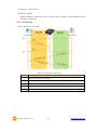
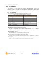
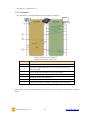
8ports Remote I/O Controller CIE-H10 User’s Manual Version 3.1 Sollae Systems Co., Ltd. http://www.ezTCP.com CIE-H10 User’s Manual Ver. 3.1 To all residents of the European Union Important environmental information about this product This symbol on this unit or the package indicates that disposal of this unit after its lifecycle could harm the environment. Do not dispose of the unit as unsorted municipal waste; it should be brought to a specialized company for recycling. It is your responsibility to return this unit to your local recycling service. Respect your local environmental regulation. If in doubt, contact your local waste disposal authorities. Sollae Systems Co., Ltd. -1- http://www.ezTCP.com CIE-H10 User’s Manual Ver. 3.1 Contents Contents ............................................................................................................................................- 2 1 Introduction .............................................................................................................................- 5 - 1.1 Introduction .......................................................................................................................................................... - 5 1.2 Application Examples ....................................................................................................................................... - 5 1.3 Components ......................................................................................................................................................... - 7 1.4 Specification ......................................................................................................................................................... - 8 - 1.4.1 H/W specification ..................................................................................................................................... - 8 1.4.2 S/W specification ...................................................................................................................................... - 8 1.5 Interface ................................................................................................................................................................. - 9 - 1.5.1 Input Ports ................................................................................................................................................... - 9 1.5.2 Output Ports ............................................................................................................................................ - 10 1.5.3 RS232 Port (DB9M) ............................................................................................................................... - 11 1.5.4 Ethernet Interface .................................................................................................................................. - 12 1.5.5 Power ........................................................................................................................................................... - 12 1.5.6 System LED ............................................................................................................................................... - 13 1.5.7 ISP Switch .................................................................................................................................................. - 13 2 Installation and Test ............................................................................................................ - 14 - 2.1 Installation .......................................................................................................................................................... - 14 - 2.1.1 Setting Network Aera .......................................................................................................................... - 14 2.2 Test operation ................................................................................................................................................... - 16 - 2.2.1 Modbus/TCP Test ................................................................................................................................... - 16 2.2.2 HTTP Test with a WEB browser ....................................................................................................... - 18 3 Configuration ....................................................................................................................... - 19 - 3.1 Configuration with ezManager ................................................................................................................. - 19 - 3.1.1 Configuration via LAN ......................................................................................................................... - 19 3.1.2 Configuration via Serial ...................................................................................................................... - 20 3.2 AT command ..................................................................................................................................................... - 21 4 Operation Modes ................................................................................................................ - 22 - 4.1 What is the Operation Mode? .................................................................................................................. - 22 4.2 How to chage the mode to another ..................................................................................................... - 22 4.3 Comparison of the each mode ................................................................................................................ - 23 4.4 Normal Mode ................................................................................................................................................... - 23 5 Methods for I/O control .................................................................................................... - 24 Sollae Systems Co., Ltd. -2- http://www.ezTCP.com CIE-H10 User’s Manual Ver. 3.1 5.1 MODBUS/TCP ................................................................................................................................................... - 24 - 5.1.1 Related Parameters ............................................................................................................................... - 24 5.1.2 Modbus/TCP Slave Mode .................................................................................................................. - 25 5.1.3 Modbus/TCP Master Mode ............................................................................................................... - 25 5.1.4 TCP Connection Modes ...................................................................................................................... - 26 5.1.5 Initial Output Value ............................................................................................................................... - 26 5.1.6 Write Pulse ................................................................................................................................................ - 26 5.2 Serialized Modbus/TCP ................................................................................................................................ - 26 5.3 Macro Mode...................................................................................................................................................... - 27 - 5.3.1 Operator..................................................................................................................................................... - 27 5.3.2 Operand ..................................................................................................................................................... - 27 5.3.3 Expression example .............................................................................................................................. - 28 5.4 Web (HTTP) ........................................................................................................................................................ - 29 - 5.4.1 Changing port number for HTTP ................................................................................................... - 29 5.4.2 Uploading Users’ Web Page ............................................................................................................. - 30 6 Communication Modes ...................................................................................................... - 31 - 6.1 TCP Server .......................................................................................................................................................... - 31 - 6.1.1 Key parameters ....................................................................................................................................... - 31 6.1.2 An Example ............................................................................................................................................... - 32 6.2 TCP Client ........................................................................................................................................................... - 33 - 6.2.1 Key parameters ....................................................................................................................................... - 33 6.2.2 An Example ............................................................................................................................................... - 34 6.3 AT Command .................................................................................................................................................... - 37 - 6.3.1 Key parameters ....................................................................................................................................... - 37 6.3.2 Examples .................................................................................................................................................... - 38 6.4 UDP ....................................................................................................................................................................... - 40 - 6.4.1 Key parameters ....................................................................................................................................... - 40 6.4.2 Examples .................................................................................................................................................... - 41 7 System Management .......................................................................................................... - 43 - 7.1 Upgrading Firmware ...................................................................................................................................... - 43 - 7.1.1 Firmware .................................................................................................................................................... - 43 7.1.2 Processes ................................................................................................................................................... - 43 7.2 Changing Webpage ....................................................................................................................................... - 45 - 7.2.1 Webpage ................................................................................................................................................... - 45 7.2.2 Processes ................................................................................................................................................... - 45 7.3 Status Monitoring ........................................................................................................................................... - 47 - 7.3.1 Using TELNET .......................................................................................................................................... - 47 Sollae Systems Co., Ltd. -3- http://www.ezTCP.com CIE-H10 User’s Manual Ver. 3.1 7.3.2 Using ezManager ................................................................................................................................... - 49 8 Additional Functions ........................................................................................................... - 51 - 8.1 Security ................................................................................................................................................................ - 51 - 8.1.1 Restriction of Access (ezTCP Firewall) .......................................................................................... - 51 8.1.2 Setting Password .................................................................................................................................... - 51 8.2 Option Tab Functions .................................................................................................................................... - 52 - 8.2.1 Notify IP Change ................................................................................................................................... - 52 8.2.2 Sending MAC Address ........................................................................................................................ - 53 8.2.3 Debugging Message ............................................................................................................................ - 53 8.3 Serial Port Tab Functions ............................................................................................................................. - 55 - 8.3.1 TELNET COM port Control Option (RFC 2217) - ①.............................................................. - 55 8.3.2 Disable TCP Transmission Delay - ② ........................................................................................... - 55 8.3.3 Data Frame Interval - ③ .................................................................................................................... - 55 8.3.4 TX interval - ④ ....................................................................................................................................... - 55 8.3.5 TCP Server / Client mode - ⑤ ........................................................................................................ - 56 8.4 Digital I/O Functions ..................................................................................................................................... - 56 - 8.4.1 Valid Time.................................................................................................................................................. - 56 8.4.2 Delay ............................................................................................................................................................ - 56 9 Self-Test in Trouble ............................................................................................................. - 57 - 9.1 Searching problem with ezManager ...................................................................................................... - 57 9.2 Connection Problem over Modbus/TCP .............................................................................................. - 58 9.3 Communication Problem over Modbus/TCP ..................................................................................... - 59 10 Technical Support, Warranty and Precaution ................................................................ - 60 - 10.1 Technical Support ........................................................................................................................................... - 60 10.2 Warranty .............................................................................................................................................................. - 60 - 10.2.1 Refund ......................................................................................................................................................... - 60 10.2.2 Free Repair Services ............................................................................................................................. - 60 10.2.3 Charged Repair Services..................................................................................................................... - 60 10.3 Precaution........................................................................................................................................................... - 61 11 History ................................................................................................................................... - 62 - Sollae Systems Co., Ltd. -4- http://www.ezTCP.com CIE-H10 User’s Manual Ver. 3.1 Introduction 1 1.1 Introduction In the era of Ubiquitous Environment, many kinds of systems which use sensors like temperature, humidity or pressure and controlling the power of remote devices have been developing. The CIE-H10 monitors those sensors and controls the remote devices. It detects digital inputs from sensor’s outputs and controls the relay outputs. HTTP, Modbus/TCP, serialized Modbus/TCP and Macro mode can be used for these functions. The CIE-H10 can be used in another way because it equipped operation as a serial device server. 1.2 Application Examples Remote I/O device server Figure 1-1 remote I/O device server Sollae Systems Co., Ltd. -5- http://www.ezTCP.com CIE-H10 User’s Manual Ver. 3.1 Serialized Modbus/TCP Figure 1-2 serialized Modbus/TCP Internet Switch Figure 1-3 internet switch Serial Switch Figure 1-4 serial switch Sollae Systems Co., Ltd. -6- http://www.ezTCP.com CIE-H10 User’s Manual Ver. 3.1 Macro mode Figure 1-5 macro mode Serial Device Server Figure 1-6 serial device server 1.3 Components The CIE-H10’s body 5V Power Adapter RS232C Cable for PC (option) Adapter for DIN rail (option) Dry Contact Adapter (option) Sollae Systems Co., Ltd. -7- http://www.ezTCP.com CIE-H10 User’s Manual Ver. 3.1 1.4 Specification 1.4.1 H/W specification Power Input Power 5V (±10%) Current Consumption 510mA typical Size 153mm x 126mm x 32mm Weight Approximately 530g CPU ARM7 Core Interfaces Digital Input 8 ports with photo couplers Digital Output 8 ports with relays Serial Port DSUB 9 pins male Ethernet RJ45 Ethernet 10Base-T or 100Base-TX (Auto-Sensing) Network Auto MDI/MDIX(Cable Auto-sensing) Temperature Operate: 0 ~ 55℃ / Storage: -40 ~ 85℃ CE: F690501/SP-EMC000976 Certification MIC: SLS-CIE-H10 Environment Follows Europe RoHS Directive 1.4.2 S/W specification TCP, UDP, IP, ICMP, ARP, DHCP, DNS lookup, DDNS, Protocol Telnet COM Port Control Option(RFC2217), Modbus/TCP, HTTP Diagnose Online Debugging Function Normal Normal communication mode Operation ISP F/W upgrade mode Serial Configuration with the RS232 port Configuration Modbus/TCP – Slave/Master, Passive/Active Communicati on Mode I/O server Modbus/TCP Serial devices server Programs Web Browser(HTTP), Macro(Stand-alone), Serialized TCP Server/Client, AT emulation, UDP ezManager Configuration program via LAN ModMap Modbus/TCP Application for Windows Sollae Systems Co., Ltd. -8- http://www.ezTCP.com CIE-H10 User’s Manual Ver. 3.1 1.5 Interface 1.5.1 Input Ports Because each of the CIE-H10’s input ports are isolated by photo-couplers, users don’t need to be worried about the polarity. The circuit of the input port is shown in the figure below. The [EXTERNAL INPUT1] and [EXTERNAL INPUT2] port should be interfaced with the user device. 3.3V 10K 1K(1/4W) EXTERNAL INPUT 1 TO PROCESSOR EXTERNAL INPUT 2 1K(1/4W) Figure 1-7 a circuit of the input port The voltage specification of the input port is as follows: Table 1-1 the voltage specification of the input ports Max. Input Voltage DC24V VIH Min. 1.8V H 1 VIL Max. 1.2V L 0 The input port is interfaced with a 5mm terminal block. Thus, use a (-) shaped screwdriver to connect it with the user device. Types for giving input The type of the input ports is the wet contact by photo-couplers. This type needs two wires which have difference of voltage level for making an input signal. However, there is an accessory which changes the input type to dry contact. By using this, accessory, you can give an input signal (ON or HIGH) with switch (relay) interface. The input ports are designed only for monitoring signals. Sollae Systems Co., Ltd. -9- http://www.ezTCP.com CIE-H10 User’s Manual Ver. 3.1 1.5.2 Output Ports The output ports of the CIE-H10 are interfaced to relays as shown below. The [EXTERNAL OUTPUT1] and [EXTERNAL OUTPUT2] port should be interfaced with the user device. EXTERNAL OUTPUT1 2 3 EXTERNAL OUTPUT2 1 5 VCC_5V FROM_PROCESSOR RELAY SPST Figure 1-8 a circuit of the output port The output port operates are as in the following Table 1-2 values of the output port value relay contact 0 OFF (open) 1 ON (short) The allowed output ports’ electrical current of voltage conditions are as in the following: Table 1-3 voltage conditions of the output port Voltage Condition Allowed current DC28V 5A The output ports are interfaced with a 5mm terminal block, use a (-) shaped screwdriver to connect it with users’ devices. Sollae Systems Co., Ltd. - 10 - http://www.ezTCP.com CIE-H10 User’s Manual Ver. 3.1 1.5.3 RS232 Port (DB9M) The CIE-H10 has an RS232 port supporting from 300 bps to 230,400 bps. This port is for connecting users’ serial devices to Ethernet (TCP/IP) including the “Serialized Modbus/TCP”. Pin Assignment Table 1-4 pin assignment of the RS232 port No. name description level Dir. Etc. 1 DCD Data Carrier Detect RS232 Input NC 2 RXD Receive Data RS232 Input required 3 TXD Transmit Data RS232 Output required 4 DTR Data Terminal Ready RS232 Output option 5 GND Ground Ground - required 6 DSR Data Set Ready RS232 Input option 7 RTS Request To Send RS232 Output option 8 CTS Clear To Send RS232 Input option 9 RI Ring Indicator RS232 Input NC NC: Not Connected Data bits, Parity, and Stop bit Table 1-5 parameters of the RS232 port items available values Data bits 8, 7, 6, 5 Parity None, Even, Odd, Mark, Space Stop bit 1, 1.5, 2 Flow Control The CIE-H10 supports RTS/CTS and DTR/DSR (Hardware) Flow Control. Telnet COM Port Control Option The CIE-H10 has Telnet COM Port Control Option function that is specified by RFC2217. It plays a role of an access server. If the Telnet COM Port Control Option is enabled, the CIE-H10 sends the CTS, DSR control signal to the communication counterpart, and sets its serial port items (RTS, DTR, Baud rate, data bits, parity, stop bit) after getting information from the communication counterpart. Sollae Systems Co., Ltd. - 11 - http://www.ezTCP.com CIE-H10 User’s Manual Ver. 3.1 1.5.4 Ethernet Interface An RJ45 connector is for the network interface of the CIE-H10. You can use a UTP cable. It automatically senses 10Mbits or 100Mbits Ethernet. It also provides auto MDI/MDIX function that can automatically sense 1:1 cable or cross over cable. Each Ethernet device has its own hardware address. The hardware address of the CIE-H10 is fixed in the factory before being shipped to the market. (The hardware address is also known as the MAC address) Figure 1-9 the RJ45 connector 1.5.5 Power DC 5V is used for the power. The specification of the power jack is as following: Figure 1-10 the power specification Sollae Systems Co., Ltd. - 12 - http://www.ezTCP.com CIE-H10 User’s Manual Ver. 3.1 1.5.6 System LED The CIE-H10 has 21 lamps to show the current system status. Each lamp shows the following status: Table 1-6 status of the system LED mode Common name color LED status description PWR Red On supplying the power Green On connected with 100M bit network Red On connected with 10M bit network RXD Yellow blinks receiving data from the Ethernet TXD Green blinks transferring data to the Ethernet LINK blinks every second STS Normal Yellow mode Serial Configuration mode blinks 4 times without being assigned an IP at once address by DHCP or PPPoE On establishing a Modbus/TCP connection DI Yellow On when input ports’ signal is ON DO Green On when output ports’ signal is ON blinks operating for the serial configuration simultaneously mode Off operating for the ISP mode LINK, STS, RXD, - TXD ISP mode 1.5.7 assigned an IP address STS Yellow ISP Switch There is an ISP switch located on the side of the product. It is a switch that will allow the CIE-H10 to be operated as serial configuration mode or ISP mode. If the switch is pressed between 20ms and 1s, the CIE-H10 changes the mode into the serial configuration mode. In this mode, you can configure the environment parameters through the RS232 port. If the button is pressed over a second or the power is supplied when you are pressing the button, the CIE-H10 is operated as ISP mode. Figure 1-11 ISP switch In the ISP and Serial Configuration mode, the designed password and access restriction could be restored or reset. Use these modes when you are faced with the problems. Sollae Systems Co., Ltd. - 13 - http://www.ezTCP.com CIE-H10 User’s Manual Ver. 3.1 2 Installation and Test 2.1 Installation Let’s look into the operation of the CIE-H10. Basically, the set of input ports and output ports are independently used. Thus, you can use the input ports only or the output ports only. On the other hand, you can also correlatively use those ports by using the MACRO mode on the output ports. Before testing the CIE-H10, you should connect the Ethernet port to a PC. It will be no problem that the Ethernet connection is established through network hubs. Figure 2-1 the connection between H10 and a PC 2.1.1 Setting Network Aera This step is for setting both the CIE-H10 and your PC to be located the same network. If only they are, the TCP connection between them can be established. Setting of the PC Add or change the IP address of the network adapter on your PC. Get into the menu of [Windows Control Panel] >> [Network Connections] >> [Properties of the Network Adapter – with right click of your mouse]. Then, you can show the properties of [Internet Protocol (TCP/IP)]. Press the [Advanced..] button and add an IP Address like the figure below. Figure 2-2 adding / changing an IP address Sollae Systems Co., Ltd. - 14 - http://www.ezTCP.com CIE-H10 User’s Manual Ver. 3.1 Setting of the CIE-H10 ezManager is the management tool for parameters of the CIE-H10. This application is only for MS Windows and this is comfortable to use because it doesn’t need installation process. First, search your CIE-H10 via network. All the values of parameters are set to the default values in the factory. To apply it to your system, proper values should be set via ezManager. Default values of some major parameters are listed on the table below. To do the following simple test, keep these values without any changes. Table 2-1 default values of some major parameters parameter Network Option Serial Port I/O Port value Local IP Address 10.1.0.1 Subnet Mask 255.0.0.0 Telnet Checked IP Address Search Checked Serial Type RS232 Baud Rate 19,200bps Parity NONE Data Bits 8 Stop Bit 1 Flow NONE Communication Mode T2S – TCP Server Local Port 1470 Web (HTTP) Checked Web (HTTP) Port 80 Modbus/TCP Checked Master/Slave Slave Connection Mode Passive Connection Multiple Connection 1 Peer Port 502 You can download the latest version of ezManager on the [Download] >> [Utility] page on our website. Sollae Systems Co., Ltd. - 15 - http://www.ezTCP.com CIE-H10 User’s Manual Ver. 3.1 2.2 Test operation 2.2.1 Modbus/TCP Test This is for checking the operation of Input and output ports of the CIE-H10 via Modbus/TCP. In this instruction, offered Modbus/TCP test program was used. Run ezManager. Then, you can show the window like the figure below. Figure 2-3 Modbus/TCP test program of the ezManager ① Search connected the CIE-H10 with [Search All] button. ② Select a MAC address of searched product on the [search result]. ③ Check the [Advanced Menu] option. ④ Press the [Modbus/TCP] button. ⑤ The test program will appear on the right side of the ezManager In the case of using previous versions of firmware than 3.1F the test program is shown automatically when you success in searching the product. Sollae Systems Co., Ltd. - 16 - http://www.ezTCP.com CIE-H10 User’s Manual Ver. 3.1 Modbus/TCP test Figure 2-4 Modbus/TCP test ① Input the IP address of the CIE-H10 ② Input the local port for Modbus/TCP of the CIE-H10 In a local area network, ① and ② steps can be omitted. ③ Try to connect by pressing [Connect] button ④ Under the connection, check if the Di LEDs are turned on or off with signal input ⑤ Check if Do LEDs are turned on or off with clicking the LEDs ⑥ Click the [Disconnect] button after the test is completed Sollae Systems Co., Ltd. - 17 - http://www.ezTCP.com CIE-H10 User’s Manual Ver. 3.1 2.2.2 HTTP Test with a WEB browser This is for testing the operation of Input and output ports of the CIE-H10 via HTTP. The test was implemented with a WEB browser. You can use WEB browsers such as MS Internet Explorer, Google Chrome and Mozilla Firefox. Figure 2-5 HTTP test ① Input the IP address of your CIE-H10 on the address field (Ex: 10.1.0.1). ② Check if the DI LEDs are turned on or off with HIGH signal. ③ Check if DO LEDs are turned on or off with clicking the each of LEDs. ④ Press the [Reload] button to update the status. Sollae Systems Co., Ltd. - 18 - http://www.ezTCP.com CIE-H10 User’s Manual Ver. 3.1 3 Configuration 3.1 Configuration with ezManager Figure 3-1 initial appearance of ezManager 3.1.1 Configuration via LAN Checklists Make sure of the connection between your PC and the CIE-H10 via Ethernet. If they are in the same network, [MAC Address search] button can be used. If they aren’t, only [IP Address search] is allowed to use. Procedures Figure 3-2 procedures for configuration via LAN Sollae Systems Co., Ltd. - 19 - http://www.ezTCP.com CIE-H10 User’s Manual Ver. 3.1 3.1.2 Configuration via Serial Checklists Make sure of the connection between your PC and the CIE-H10 using a RS232 cross cable. The CIE-H10 has to be operating in the [Serial Configuration] mode. You make the CIE-H10 operates in the serial configuration mode by pressing the ISP- button less than 1 second. After then, read the setting on the [Serial] tab. Procedures Figure 3-3 procedures for configuration via serial port Step 2, Reading Figure 3-4 reading procedure via serial ① Choose the [Serial] tab. ② Select the COM port which is the device is connected. ③ Open the COM port pressing the [Open] button. ④ Load the setting with the [Read] button. If you want to know more specific manners of setting, please refer to the document “ezManager Users’ Manual” on the [Download] >> [Technical Documents] page of our website. Sollae Systems Co., Ltd. - 20 - http://www.ezTCP.com CIE-H10 User’s Manual Ver. 3.1 3.2 AT command In the AT command mode, you can change some parameters through the serial port. Checklists Make sure of the connection between your PC and the CIE-H10 using a RS232 cross cable. All the parameters of the serial port between the CIE-H10 and the Terminal of your PC should be the same. In the AT command mode, you can change some parameters through the serial port. Figure 3-5 setting the communication mode to the AT command Procedures Figure 3-6 procedures for configuration with AT command Table 3-1 parameters which are available to change with AT command Division IP Address related items A TCP connection related items Option Available parameters Local IP Address, DHCP, PPPoE, Subnet Mask, Gateway IP Address, DNS IP Address, ··· Local Port, Peer Address (IP Address or Host name), Peer Port, ··· ESC code sending option, timeout, ··· Including above items, rest of parameters can be set by ezManager Sollae Systems Co., Ltd. - 21 - http://www.ezTCP.com CIE-H10 User’s Manual Ver. 3.1 4 Operation Modes 4.1 What is the Operation Mode? Each of three operation modes are designed for specific purposes, and those are as follows: Normal mode This mode is for normal data communication and has 5 different communication modes. Configuring parameters is also available in this mode. Serial configuration mode This mode is for configuring environmental parameters through the RS-232 port. ISP mode This mode is for upgrading firmware. In addition, you can set environmental parameters even though the security options are activated and you can also reset the security options. 4.2 How to chage the mode to another Figure 4-1 how to initiate each operation mode Sollae Systems Co., Ltd. - 22 - http://www.ezTCP.com CIE-H10 User’s Manual Ver. 3.1 4.3 Comparison of the each mode The following table shows summaries of the each mode. Table 4-1 comparison of the each mode name Normal Serial Configuration serial port Configured Supply the power. value Press the ISP button shortly between 10ms and 1s. 115200/N/8/1 Supply the power with pressing the ISP button or ISP 4.4 entering 115200/N/8/1 press the ISP button over 1 sec in other modes. Normal Mode In normal mode, there are four types of ways to monitor and control I/O and of additional operations as a serial-Ethernet converter. I/O controller Table 4-2 digital I/O control types type Modbus/TCP Serialized Modbus/TCP Macro WEB(HTTP) description Control and monitor the I/O of the CIE-H10 via Modbus/TCP. It supports both master and slave mode. CIE-H10 communicates through the RS232 port using the data format of Modbus/TCP. Users can automatically control the output ports by setting MACRO using some basic formula of Boolean Algebra. Users can monitor and control the CIE-H10 via HTTP serial-Ethernet converter The CIE-H10 can be used as a serial-Ethernet converter. There are four communication modes in this operation. Table 4-3 comparison of four communication modes modifying name protocol connection software of serial devices TCP Server TCP Client TCP AT Command UDP Sollae Systems Co., Ltd. UDP serial configuration topology Passive - Not available 1:1 Active - Not available 1:1 Either Required Available 1:1 - - Not available N:M - 23 - http://www.ezTCP.com CIE-H10 User’s Manual Ver. 3.1 5 Methods for I/O control 5.1 MODBUS/TCP The CIE-H10 supports Modbus/TCP. By using this protocol, it remotely monitors and controls I/O devices. To use this method, users’ application should support this protocol. 5.1.1 Related Parameters Table 5-1 Modbus/TCP related parameters parameter Modbus/TCP Slave Master Poll Interval Unit ID Input Port Base Address Output Port Base Address Using Modbus/TCP for controlling I/O ports of the CIE-H10. The slave responses by queries from the Master The Master sends queries to the slaves the period for sending queries (Unit: ms, Minimum value: 10) ID for identifying the device or the pair of devices. Initial address of the input ports Initial address of the output ports Passive Connection waiting for accepting a Modbus/TCP connection Active Connection requesting a Modbus/TCP connection Multiple Connection Control Method of (FC XX) Control Method of (AND/OR) The numbers for multiple Modbus/TCP connections. Control method for the output ports of the slave (Single / Multiple) Control method for the output ports of the master (AND / OR) Peer Address Peer’s IP address when the CIE-H10 performs active connections Peer Port (Active) Peer’s local port when the CIE-H10 performs active connections Peer Port (Passive) Local port Input Change Notification Macro Initial State description A function for immediate notification with changing the IP address. Applying macro function on the output port Output port value when the CIE-H10 boots up. The difference between the values of [Input port base address] and [Output port base address] should be at least 8. Sollae Systems Co., Ltd. - 24 - http://www.ezTCP.com CIE-H10 User’s Manual Ver. 3.1 5.1.2 Modbus/TCP Slave Mode According to the standard Modbus/TCP users can use a Modbus/TCP manager to control and monitor their I/O devices. Like this standard, you can set the CIE-H10 to the [Slave] item to [Slave] mode. The [Passive] connection would be better than the [Active] in this mode and the [Peer Port] should be 502. Table 5-2 values for standard Modbus/TCP Modbus/TCP Mode Slave TCP Connection Passive TCP Port 502 Configure the proper values of [Unit ID], [Input Port Base Address], and [Output Port Base Address]. 5.1.3 Modbus/TCP Master Mode In this mode, the CIE-H10 operates as a Modbus/TCP master. As a master the CIE-H10 sends queries which read the values of the input ports and which change the values of the output ports to the Modbus/TCP slave devices. At this time, the CIE-H10 controls the output ports with not only bit unit (individually) but also word unit (at once) FC 16(Multiple) CIE-H10 controls the output ports and monitors the input ports of slaves with WORD unit by FC16 (write multiple register) and FC 03 (read multiple register) FC 05(Single) CIE-H10 controls the output ports and monitors the input ports of slaves with BIT unit by FC05 (write coil) and FC02 (read input discretes). Sollae Systems Co., Ltd. - 25 - http://www.ezTCP.com CIE-H10 User’s Manual Ver. 3.1 5.1.4 TCP Connection Modes In the standard of Modbus TCP, the master program should make a connection to the slave using port number 502. However, sometimes Modbus/TCP devices should try connecting to the master actively. For this case, the CIE-H10 supports the active connection mode. Table 5-3 the passive / active connection The passive connection The active connection - standard Modbus/TCP - Remote host connects to the CIE-H10. - Port number that is used for communication must be designated - The CIE-H10 tries to establish a connection to the remote host - The IP address (or host name) and port number of the remote host is required 5.1.5 Initial Output Value The initial value of the CIE-H10’s output port can be configured. Depending on the value of [Initial State] at the boot time, output ports are set to ON or OFF. 5.1.6 Write Pulse By using the function code 105, you can give the signal of pulse type to the output ports. This means the output signal is kept during specified time configured by users. For more details about the Modbus/TCP protocol, please refer to the document on the [Download] >> [Technical Documents] page of our web site. 5.2 Serialized Modbus/TCP Since 1.3A firmware, serialized Modbus/TCP mode had been added on the firmware. In this mode, the CIE-H10 sends and receives Modbus/TCP data via the serial port. By using this mode, you can monitor and control the I/O ports of the CIE-H10 through the RS232 port. Note that if you are using this mode, you can’t control the output ports of the CIE-H10 with HTTP or Modbus/TCP. And also, the TCP and UDP data communication for serial devices cannot be activated. Sollae Systems Co., Ltd. - 26 - http://www.ezTCP.com CIE-H10 User’s Manual Ver. 3.1 5.3 Macro Mode This mode let users set the values of the output ports with simple macros. The CIE-H10 reflects the values according to the macro expressions which are configured by users in advance. It will be useful when users set the output values automatically from combinations of inputs. Check [Macro] options on ezManager to activate this mode. 5.3.1 Operator The algorithm used in the Macro mode is Boolean algebra. In this case, the AND, OR, NOT are used as operators. Parenthesis may also be used. The priority of operators is in the following order: parenthesis > NOT > AND > OR. Each operator is represented by the following symbols. Table 5-4 the operators name sign description Since calculations within the parenthesis have the Parenthesis ( ) highest priority, they will be calculated first. Parenthesis may be nested used. Operand that follows NOT operator is toggled. (If NOT / operand is 0, it will be changed to 1. If it is 1, it will be changed to 0.) If Operand values that surrounds AND operator AND * all 1, the result value will be 1. If either one of them is 0, the result will be 0 as well. If Operand values that surrounds AND operator OR + all 0, the result value will be 0. If either one of them is 1, the result will be 1 5.3.2 Operand Operands used in macro mode are each input port. Each input port is designated with i0 ~ i7 symbol based on their sequence. Since capital letters are not recognized, they can also be written as I0 ~I7. The output ports couldn’t be used as an operand. Sollae Systems Co., Ltd. - 27 - http://www.ezTCP.com CIE-H10 User’s Manual Ver. 3.1 5.3.3 Expression example Here are some examples. In the expressions, spaces between the two operands will be ignored. Table 5-5 an example of equation Perform OR for i0 and i1. Do0 i0 + i1 Do2 i0 * /(i1 + i7) Spaces in between two operands may be ignored Perform NOT with value from performing OR for i1 and i7. Then, perform AND with that value and i0 Based on input values from three input ports, the output values are as follows. Table 5-6 the logic table of the table 5-5 Input port value Output port value i0 i1 i7 Do0 Do2 0 0 0 0 0 0 0 1 0 0 0 1 0 1 0 0 1 1 1 0 1 0 0 1 1 1 0 1 1 0 1 1 0 1 0 1 1 1 1 0 Sollae Systems Co., Ltd. - 28 - http://www.ezTCP.com CIE-H10 User’s Manual Ver. 3.1 5.4 Web (HTTP) After starting the web browser, type the CIE-H10’s IP address after typing http:// in the address window to connect to the CIE-H10. If passwords for the CIE-H10 are designated, the following window will be popped up. Figure 5-1 authentication with password ① the CIE-H10 does not care the [User name]. (You don’t have to fill the box) ② [Password] should be the same with password which is set through the ezManager. 5.4.1 Changing port number for HTTP In case you cannot use the port number 80(default port number for HTTP) because the ISP (Internet Service Provider) blocks the port, you can change that port number. Figure 5-2 changing port number for HTTP ① Input a port number to the [Web(HTTP) Port] box. ② Input the IP address of the CIE-H10 with changed port number and “http://” Sollae Systems Co., Ltd. - 29 - http://www.ezTCP.com CIE-H10 User’s Manual Ver. 3.1 5.4.2 Uploading Users’ Web Page 1.3A or subsequent versions of firmware support uploading custom web page. This function is available to anyone who can make HTML files. If you get some simple syntax, it is possible to monitor and control the I/O ports with your homepage interface. Upgrading Boot and Firmware To use this function, it is needed for users who have been using 1.5 version of boot and 1.2C version of firmware or lower versions. If you have already got the updated products, you don’t need this process. Figure 5-3 examples of web page ① Default image ② Default text ③ No comment ④ Sample01 ⑤ Sample02 ⑥ Simple image ⑦ Simple text If you cannot use this function, you should upgrade the version of boot even though your CIE-H10 has the latest version of F/W. For more information about the upgrading boot, please refer to the “CIE-H10_upgrading Boot and F/W” document on the [Download] >> [Technical Documents] page. Sollae Systems Co., Ltd. - 30 - http://www.ezTCP.com CIE-H10 User’s Manual Ver. 3.1 6 Communication Modes The CIE-H10 provides RS232↔TCP/IP conversion function along with input/output port monitoring and controlling function. 6.1 TCP Server In this mode, the CIE-H10 functions as a TCP server. The CIE-H10 waits for a TCP connection from remote hosts. Once a host tries to connect to the CIE-H10, it responses to that request. After the connection is established, the CIE-H10 converts the raw data from the serial port to TCP/IP packets and sends the packets to the network and vice versa. 6.1.1 Key parameters Local Port This is a server’s port number which is used in the TCP connection. Event Byte With setting event bytes, users can handle the serial data before a TCP connection is established. Table 6-1 Event Byte Value 0 Otherwise (512 or under) Description CIE-H10 doesn’t send the data CIE-H10 sends the data right after a connection is established. 512 or under bytes are strongly recommended. Timeout If there is no transmission of data for amount of time which is set to this parameter, the CIE-H10 tries to terminate established a TCP connection. Notify IP Change This function is for notifying information about changed IP address to a server. Not only the TCP/UDP protocol but Dynamic Domain Name Service (DDNS) can be used. Restriction of Access(ezTCP Firewall) Users can block TCP connections from unauthorized hosts by using this option. Both IP and MAC address are available. Sollae Systems Co., Ltd. - 31 - http://www.ezTCP.com CIE-H10 User’s Manual Ver. 3.1 6.1.2 An Example An example as a TCP server Figure 6-1 TCP server Table 6-2 descriptions of each state Point State ~ H10 is waiting for request segments of a TCP connection ① Remote host has sent a request (SYN) segment ~ Processes of the connection ② The connection has been established ~ Data communication on both sides Sollae Systems Co., Ltd. - 32 - http://www.ezTCP.com CIE-H10 User’s Manual Ver. 3.1 6.2 TCP Client In this mode, the CIE-H10 functions as a TCP client. The CIE-H10 sends request segments to a remote host with information of [Peer Address] and [Peer Port]. Under situation that the TCP server works fine with the specific port, the connection will be established. After then, the CIE-H10 converts the raw data from the serial port to TCP/IP data and sends them to the network and vice versa. 6.2.1 Key parameters Peer Address This item should be an address of a remote host who is waiting requests of a TCP connection. Peer Port [Peer Port] should be the port number which is designated by the remote host. Event Byte The CIE-H10 decides the time to send request segments for the TCP connection with this parameter. Table 6-3 the operation of Event Byte 1 Value 0 Otherwise (512 or under) Description CIE-H10 sends a request segment of the TCP connection right after it boots up CIE-H10 sends the segment right after it received amount of data which is set to the [Event Byte] from the serial port In addition, users can handle the serial data before a TCP connection is established with this parameter. Table 6-4 the operation of Event Byte 2 Value 0 Otherwise (512 or under) Description CIE-H10 doesn’t send the data. CIE-H10 sends the data right after a connection is established. 512 or under bytes are strongly recommended. Timeout If there is no transmission of data for amount of time which is set to this parameter, the CIE-H10 tries to terminate the established TCP connection. TCP Server This check option is enable the TCP server / client mode. In this mode, the CIE-H10 can be operated as a TCP server or client without changing its setting. Sollae Systems Co., Ltd. - 33 - http://www.ezTCP.com CIE-H10 User’s Manual Ver. 3.1 DNS IP Address [DNS IP Address] needs when users use host name instead of the IP address on the [Peer Port] parameter. 6.2.2 An Example An example of TCP client Figure 6-2 time chart for a situation that [Event Byte] is set to 0 Table 6-5 descriptions of each state Point State ~ Before the power is supplied ① Sends request segments of a TCP connection right after it boots up ~ Processes of the disconnection ② The connection has been established ~ Data communication on both sides Sollae Systems Co., Ltd. - 34 - http://www.ezTCP.com CIE-H10 User’s Manual Ver. 3.1 TCP Server/Client mode In the TCP client mode, the [TCP Server] check option is activated. If you check this option, the CIE-H10 operates as the TCP server/client mode. In this mode, the CIEH10 can establish a TCP connection both actively and passively without changing any setting. Figure 6-3 setting the TCP server/client mode ① Select the [COD – TCP Client] mode ② Input an IP address and port number of a remote host ③ Check the [TCP Server] check box ④ Input the [Local Port] for waiting for the request segments of a TCP connection ⑤ Set the [Event Byte] to value more than 1 byte ⑥ Set the [Timeout] to proper value Sollae Systems Co., Ltd. - 35 - http://www.ezTCP.com CIE-H10 User’s Manual Ver. 3.1 Fig 6-4 time chart for activating [TCP Server] option Table 6-6 descriptions of each state Point State ~ H10 is waiting for request segments of a TCP connection ① The connection has been established ~ H10 is on line and processes of the disconnection ② The connection has been terminated ~ Both sides are offline ③ Sends a request segment of a TCP connection The TCP Server/Client mode only can be a useful option under condition of using [Event Byte] and [Timeout]. Note that only one TCP connection can be established at the same time, so users should consider setting [Timeout] properly. For more details about the TCP Server/Client mode, please refer to the technical document on the [Download] >> [Technical Documents] page of our web site. Sollae Systems Co., Ltd. - 36 - http://www.ezTCP.com CIE-H10 User’s Manual Ver. 3.1 6.3 AT Command AT command is a mode which users control the CIE-H10 with AT command like controlling modem. In this mode, active and passive TCP connections are available. And users are allowed to configure some environmental parameters with extended commands. 6.3.1 Key parameters The configuration should be implemented via the serial port of H10 Table 6-7 some of extended commands for configuration Commands Description Examples +PLIP Local IP Address AT+PLIP=10.1.0.1<CR> +PLP Local Port AT+PLP=1470<CR> +PRIP Peer IP Address AT+PRIP=10.1.0.2<CR> +PRP Peer Port AT+PRP=1470<CR> +PDC DHCP AT+PDC=1 (ON)<CR> +PTO Timeout AT+PTO=10<CR> +PWP Store setting AT+PWP<CR> Related items with the IP Address and Local Port As well as the local port, the IP address related parameters such as IP Address, Subnet Mask and Gateway IP Address can be set. Peer Address / Peer Port IP address and local port of a remote host are can be set. Type of assigning the IP address: Manual, DHCP, PPPoE Not only manual setting, also automatic assigning protocol (DHCP, PPPoE) is available. The others Some of options including [Timeout] can be configured in this mode. Sollae Systems Co., Ltd. - 37 - http://www.ezTCP.com CIE-H10 User’s Manual Ver. 3.1 6.3.2 Examples TCP Server – setting parameters and a passive connection Figure 6-5 a passive TCP connection Table 6-8 descriptions of each state Point ~ ① State Set parameters in the AT command mode H10 waits request segments of a TCP connection with the ATA command ~ H10 is waiting for requests of a TCP connection ② A remote host has sent SYN segment to H10 ~ Processes of the TCP connection ③ TCP connection has been established ~ The CIE-H10 sends “CONNECT” message to the serial port Most of the response messages from the serial port of the CIE-H10 are omitted on above figure. Sollae Systems Co., Ltd. - 38 - http://www.ezTCP.com CIE-H10 User’s Manual Ver. 3.1 TCP Client – setting parameters and an active connection Figure 6-6 an active TCP connection Table 6-9 descriptions of each state Point ~ ① State Set parameters in the AT command mode H10 sends a request segment of a TCP connection with the ATD command. ~ Processes of the TCP connection ② The TCP connection has been established. ~ The CIE-H10 sends “CONNECT” message to the serial port. For more information about this, please refer to the “ATC mode” on the [Download] >> [Technical Documents] menu of our web site. Sollae Systems Co., Ltd. - 39 - http://www.ezTCP.com CIE-H10 User’s Manual Ver. 3.1 6.4 UDP UDP has no processes of a connection. In this mode, data is sent in block units. Therefore, data that comes through the CIE-H10’s serial port must be classified in block units to be sent elsewhere. 6.4.1 Key parameters Block Size(Byte) [Block Size] means the size of a block in UDP mode. Its unit is byte. The size of bytes are come into the serial port, the CIE-H10 sends them as one block to the network. The maximum value could be 1460 bytes. Data Frame Interval [Data Frame Interval] means the time for gathering data to make one block. Its unit is 10ms. If there is no transmission during the time which is set to this value, the CIEH10 sends gathered data in the buffer as one block to the network. Once one of the parameters is sufficient, the block size is decided as the condition. Dynamic update of Peer host If users set the value of [Peer Address] and [Peer Port] to 0, [dynamic update of peer host] function is activated. By using this function, the CIE-H10 can communicate with multiple hosts without additional setting. Sollae Systems Co., Ltd. - 40 - http://www.ezTCP.com CIE-H10 User’s Manual Ver. 3.1 6.4.2 Examples Block Size: 5 bytes / Data Frame Interval: 1s (100 * 10ms) Figure 6-7 time chart for block size is 5 bytes and Data Frame Interval is 1s Table 6-10 descriptions of each state Point State ~ H10 is receiving data from the serial port ① H10 Sends 5 bytes as one block based on the [Block Size] ~ Serial device sends data “678” to the H10 ② Data “678” has arrived ~ H10 sends data from the remote host to the serial device ③ 1 second has passed ~ H10 sends data “678” based on the [Data Frame Interval] Sollae Systems Co., Ltd. - 41 - http://www.ezTCP.com CIE-H10 User’s Manual Ver. 3.1 Dynamic Update of Peer host This is a function that the CIE-H10 automatically sets its peer host with information of the last packet which is received from network. In the packet, the source address and port number is used. Table 6-11 setting for [dynamic update of peer host] function Parameter Value Peer Address 0 (None) Peer Port 0 Figure 6-8 Time chart for [dynamic update of peer host] Table 6-12 descriptions of each state Point State ~ Remote host 2 sends data to H10 ① H10 sets host 2 to peer host ~ Remote host 1 sends data to H10 ② H10 updates host 1 to peer host ~ Remote host 2 sends data again to H10 ③ H10 updates host 2 to peer host ~ H10 can communicate with remote host 2 The data “ABC”, “DE”, “FGH” are from the serial port of the CIE-H10 in the above figure. Sollae Systems Co., Ltd. - 42 - http://www.ezTCP.com CIE-H10 User’s Manual Ver. 3.1 7 System Management 7.1 Upgrading Firmware 7.1.1 Firmware Firmware is a type of software for operation of the CIE-H10. If there are needs for adding function or fixing bugs, the firmware will be modified and released. We recommend that users keep use the latest released firmware. 7.1.2 Processes Downloading the latest released firmware Download the newest firmware file. We update our homepage when a new firmware is released. You can find it on our website. Entering ISP mode Enter ISP mode to download firmware file to the CIE-H10. Run a TFTP client and ready to send the F/W file Run a TFTP client program. ezManager is equipped the client program. Click the [Change F/W / HTML] button. Figure 7-1 running TFTP client ① Check the [Advanced Menu] check box ② Click the [Change F/W / HTML] button to run TFTP client ③ Select the [Change Firmware] radio button ④ Input the IP address of the CIE-H10 to the [Local IP Address] text box ⑤ Press the [Open Firmware / HTML] button and choose the firmware file Sollae Systems Co., Ltd. - 43 - http://www.ezTCP.com CIE-H10 User’s Manual Ver. 3.1 Checking firmware file and Sending Figure 7-2 sending firmware file ① Check if the name and path of the firmware file are correct ② Click the [Send] button ③ Confirm the completed message Sollae Systems Co., Ltd. - 44 - http://www.ezTCP.com CIE-H10 User’s Manual Ver. 3.1 7.2 Changing Webpage 7.2.1 Webpage To monitor and control, homepage should be uploaded in the CIE-H10. 7.2.2 Processes Making Users‘ webpage or Downloading sample files Make your own webpage file or use sample webpage files which we’ve been offering on our web site. Entering ISP mode Enter ISP mode to send HTML files to the CIE-H10. Running a TFTP client and ready to send the HTML files Run a TFTP client program. ezManager is equipped the client program. Click the [Change F/W / HTML] button. Figure 7-3 running TFTP client ① Check the [Advanced Menu] check box ② Click the [Change F/W / HTML] button to run TFTP client ③ Select the [Change HTML] radio button ④ Input the IP address of the CIE-H10 to the [Local IP Address] text box ⑤ Press the [Open Firmware / HTML] button and choose the HTML file Sollae Systems Co., Ltd. - 45 - http://www.ezTCP.com CIE-H10 User’s Manual Ver. 3.1 Checking firmware file and Sending Figure 7-4 sending firmware file ① Check if the name and path of the firmware file are correct ② Click the [Send] button ③ Confirm the completed message Sollae Systems Co., Ltd. - 46 - http://www.ezTCP.com CIE-H10 User’s Manual Ver. 3.1 7.3 Status Monitoring 7.3.1 Using TELNET Once the [TELNET] option is activated, users can remotely log in to the CIE-H10. If a password is set, users should input the password. After then, messages from the CIE-H10 appear like the figure below. Figure 7-5 log in to the CIE-H10 on TELNET You can check multiple states with the following commands. Table 7-1 commands for checking states command option description usage net Network Status lsh>st net sio Serial Port Status lsh>st sio uptime System Uptime lsh>st uptime sc [OP1][OP2] Session Control lsh>sc com1 close sd [OP1][OP2] Capturing Serial Data lsh>sd 1 100 st st net “st net” command displays present network states of all sessions. Figure 7-6 “st net command” Sollae Systems Co., Ltd. - 47 - http://www.ezTCP.com CIE-H10 User’s Manual Ver. 3.1 st sio “st sio” command displays the number of bytes for the serial port. Figure 7-7 “st sio” command st uptime “st uptime” command shows amount of time since H10 has booted up. Figure 7-8 “st uptime” command sc “sc” command is used when users close a session. [OP1] means the name of session, and [OP2] should be “CLOSE”. Figure 7-9 “sc” command In the case of the “sc” command you should use only small letters. sd “sd” command is for capturing serial data. [OP1] means name of the session, [OP2] means period, which has a 10ms unit, for the capture. Figure 7-10 “sd” command Sollae Systems Co., Ltd. - 48 - http://www.ezTCP.com CIE-H10 User’s Manual Ver. 3.1 7.3.2 Using ezManager Status of the CIE-H10 can be monitored by [Status] button on ezManager. By using the [Refresh Every 1 Second] option in the status window, the status is automatically updated in every second. Figure 7-11 status window of ezManager FIRMWARE VERSION The name of model name and the version of firmware are displayed here. SYSTEM UPTIME Amount of time is displayed since the CIE-H10 boots up. IP4 NETWORK INFORMATION All information about related items with IP Address including the MAC address is shown here. It works even if the IP address is assigned from DHCP or PPPoE. Sollae Systems Co., Ltd. - 49 - http://www.ezTCP.com CIE-H10 User’s Manual Ver. 3.1 TCP STATE TCP status of each port is shown in this section. Table 7-2 TCP STATE Message Description LISTEN waiting for requests of a TCP connection CLOSE a TCP connection is closed SYN_SENT ESTABLISHED N/A send “SYN” segment to make a TCP connection When a TCP connection is established In UDP mode SERIAL STATUS Amount of data in every buffer is displayed. The unit is byte. Table 7-3 SERIAL STATUS Buffer Description sio_rx The number of data which is received from the COM port net_tx The number of data which is sent to the remote host net_rx The number of data which is received from the remote host sio_tx The number of data which is sent to the COM port I/O PORT STATUS This represents I/O ports’ status. ‘1’ means HIGH(ON) and ‘0’ means LOW(OFF). ARP TABLE This part shows ARP table on the CIE-H10. When a TCP connection is established or UDP data communication is performed, the information of IP and MAC address is automatically stored in the ARP table. This information is held for 1 minute. When 50 seconds is passed, the CIE-H10 starts broadcasting the ARP packet again. If there is no response until the time is 0, the information is removed. If there is a response, the time is updated 60 seconds again. TCP/IP Connection In this section, the same information with TCP STATE is displayed with IP address and port number. A difference is that users can terminate a TCP connection. When right click on a session, a small pop-up window is created. Password This text box is activated when the CIE-H10 has a password. If users want to close the TCP connection, this password has to be correctly filled. Refresh Every 1 Second. If this option is checked, ezManager sends query in every second. Sollae Systems Co., Ltd. - 50 - http://www.ezTCP.com CIE-H10 User’s Manual Ver. 3.1 8 Additional Functions 8.1 Security 8.1.1 Restriction of Access (ezTCP Firewall) On the [Option] tab of ezManager, users can set restriction of access function with filtering MAC and IP address. Allowed MAC Address If this option has a value of MAC address, the device which has the MAC address is only permitted to access. Allowed IP Address This is for qualifying hosts with IP address or range of IP address. The range is defined by multiplying [IP address] and [Network Mask] in bit unit. Examples Table 8-1 examples of defining allowed IP range IP Address Network Mask Allowed IP Address Range 10.1.0.1 255.0.0.0 10.1.0.1 ∼ 10.255.255.254 10.1.0.1 255.255.255.0 10.1.0.1 ∼ 10.1.0.254 192.168.1.4 255.255.255.255 192.168.1.4 Apply to ezManager [Apply to ezManager] is for applying above two restrictions to ezManager functions like [Search], [Read], [Write] and etc. 8.1.2 Setting Password A password can be used for protecting the CIE-H10 from TELNET login or changing environmental parameters by hosts which are not qualified. The maximum length is 8 bytes of Alphabet or number. When you want to revoke all of these restrictions, change the mode of the CIE-H10 to the ISP mode. All restrictions are removable and communication with ezManager is revoked in the ISP mode. Sollae Systems Co., Ltd. - 51 - http://www.ezTCP.com CIE-H10 User’s Manual Ver. 3.1 8.2 Option Tab Functions 8.2.1 Notify IP Change The CIE-H10 can be a TCP server even though it is assigned the IP address automatically. Using [Notify IP Change] function, it sends its IP address with the host name to the specific server. There are 3 types (DDNS, TCP and UDP) of functions provided. Dynamic Domain Name Service (DDNS) The CIE-H10 supports DDNS function offered by DynDNS to manage its changed IP address as a host name. Therefore, you have to make an account and create host names on the website of DynDNS before use this. All about service usage of an account could be changed according to the policy of DynDNS. Homepage of DynDNS: http://dyn.com/dns/ Figure 8-1 setting DDNS ① Select the [DDNS (dyndns.org)] item. ② 40,320 is a fixed value. ③ Input the ID of DDNS account. ④ Input the password of the account. ⑤ Input one of the host names which you created on your account. TCP/UDP In case you have an own server and want to manage the information about changed IP addresses, you are allowed to use TCP/UDP for using this option. The [Data Type] can be selected as ASCII or hexadecimal, and the [Interval] is available on configuration. For more information about this, please refer to the “Notify IP Change” on the [Download] >> [Technical Documents] menu of our web site. Sollae Systems Co., Ltd. - 52 - http://www.ezTCP.com CIE-H10 User’s Manual Ver. 3.1 8.2.2 Sending MAC Address [Sending MAC Address] is a function that the CIE-H10 sends its MAC address to the remote host right after the connection is established. By using this function, a server can identify multiple devices with the information. Figure 8-2 setting of Sending MAC Address function ① Move to the [Option] tab. ② Check the [Send MAC Address] option. 8.2.3 Debugging Message By using [Debugging] option, users can receive debugging messages from the CIE-H10 on the network. When you are facing a problem about the TCP connection or data communication, please use this function and send us the stored file. We can use it for finding out the reason of your problem. Debugging messages are broadcasted to entire network via UDP so it might cause serious network traffic. Remember you should turn the option off after using it. Setting debugging option Figure 8-3 setting debugging option ① Check the [Debugging Message] option ② Press the [Write] button ③ After check the [Advanced Menu], click the [Debugging Message] button. And then, the debugging message window is shown on your screen like the figure below. Sollae Systems Co., Ltd. - 53 - http://www.ezTCP.com CIE-H10 User’s Manual Ver. 3.1 Figure 8-4 debugging message window ① Pull down menu for selecting a network adapter ② Place for showing received debugging messages from the CIE-H10 over the network ③ Auto update to display the latest captured file on the screen of ② ④ MAC Address Information of a selected message ⑤ ~ ⑪ Unavailable ⓐ To start capturing debugging messages from the CIE-H10 ⓑ To stop capturing debugging messages from the CIE-H10 ⓒ Unavailable ⓓ [Load Message] is for loading a debugging log file to display ⓔ Closing debugging message window Sollae Systems Co., Ltd. - 54 - http://www.ezTCP.com CIE-H10 User’s Manual Ver. 3.1 8.3 Serial Port Tab Functions Figure 8-5 Serial Port Tab 8.3.1 TELNET COM port Control Option (RFC 2217) - ① This option is for sending and receiving serial port states between two devices. Users can send and receive control signals such as RTS/CTS when the states are changed. 8.3.2 Disable TCP Transmission Delay - ② If you use this option, CIE-H10 sends the data from the serial port to Ethernet as quickly as possible. 8.3.3 Data Frame Interval - ③ Before sending data from the serial port to Ethernet, ezTCP gathers data in the buffer. If there is no data during the time which is configured in the [Data Frame Interval], ezTCP will send data to the network. In case the value is set to 0, data will be sent immediately. Please set this value to 11 or higher values for correct operation. 8.3.4 TX interval - ④ This option is for preventing data loss in the case that the serial device has very small buffer size or doesn’t have a buffer. The range of the value could be from 0 to 25 and the unit is duration of sending 1 byte. For example, if you set this value to 5, each byte will be Sollae Systems Co., Ltd. - 55 - http://www.ezTCP.com CIE-H10 User’s Manual Ver. 3.1 transferred with duration of sending 5 bytes. 8.3.5 TCP Server / Client mode - ⑤ This mode is available on TCP client mode only. In this mode, you don’t need to change the mode for switching active or passive TCP connection. Note that the [Event Byte] option should be set to 1 or lager value. If you want to get more information about the above functions, refer to the technical documents on the [Download] >> [Technical documents] page at our web site. 8.4 Digital I/O Functions 8.4.1 Valid Time The CIE-H10 only recognizes signals of the input ports as the valid signals when the signal lasts for the [Valid Time]. If the signals are not maintained during the [Valid Time], the input signals will be ignored. The unit used for the [Valid Time] is 1ms. However, because the accuracy is only guaranteed in 10ms, the designated values are rounded down in units of 10ms. 8.4.2 Delay The CIE-H10 gives output values to the output ports after the amount of time has set in the [Delay]. If users set the value of [Delay] to 0, the CIE-H10 gives the output value to the output port immediately. The unit used for the [Delay] is 1ms. However, because the accuracy is only guaranteed in 10ms, the designated values are rounded down in units of 10ms. If the timer for the [Delay] is already running, all the subsequent orders for giving signals to the output ports are ignored. Sollae Systems Co., Ltd. - 56 - http://www.ezTCP.com CIE-H10 User’s Manual Ver. 3.1 9 Self-Test in Trouble When users are in trouble with the CIE-H10, make sure of the following steps first. 9.1 Searching problem with ezManager Confirming types of configuration utility The CIE-H10 can be configured by ezManager. Cancelling the Firewall operation In case of being blocked by firewalls of personal computer or network block, you must cancel all the firewalls before searching the CIE-H10. Most of vaccine programs have firewall functions so it can cause some trouble to search the CIE-H10. Close or pause these programs before searching the products. Stable supply of the power Check if the power is supplied continually. The red LED on the body shows that the power is switched on. Connection with the network Make sure that the network connection is fine including Ethernet cable. In this step, we recommend that users connect the CIE-H10 with PC directly or in the same network hub. Checking options of restriction In case that restriction of access is activated, the communication with ezManager will be unavailable. When users are in this situation, make the CIE-H10 operate in ISP mode. Sollae Systems Co., Ltd. - 57 - http://www.ezTCP.com CIE-H10 User’s Manual Ver. 3.1 9.2 Connection Problem over Modbus/TCP Checking parameters related with TCP/IP When the CIE-H10 has a private network IP address, personal computer’s IP address has to be the same sub network. Check if the IP address and local port number are correct. In case of a fixed IP address, the subnet mask, gateway IP address and DNS IP address should be configured. Table 9-1 major parameters related with Modbus/TCP Slave or Master Local IP Address, the connection mode (Active / Passive), Peer Address and Peer Port, Subnet Mask, Gateway IP Address, DNS IP Address, DDNS option and etc. PING Test Confirm the connection over the network by PING test. If the CIE-H10 doesn’t send any reply from the request, check the network environment. Firewall In case the networks which need strong security, the access may be denied by their firewall. Under this circumstance, users should ask the person in charge of their network to release ports which will be used. (Ex: TCP 502, UDP 50005) Operation Mode A TCP connection is not possible when the CIE-H10 is operating in the ISP or Serial Configuration mode. Connection Mode To make a TCP connection, both a server (passive mode) and a client (active mode) should exist. If there are only servers or clients, The TCP connection can’t be established. ezTCP Firewall When users set the ezTCP firewall with MAC and IP address, any hosts can’t be reachable to it except for the hosts which have the allowed MAC and IP address. Inactivate the option or check the setting is correct. Checking the TCP status TCP is a protocol connected one to one without multiple connections function. Because of this, if a device is on a TCP connection, other requests are denied. If users are in this situation, check the network status by connecting on TELNET or using ezManager. Sollae Systems Co., Ltd. - 58 - http://www.ezTCP.com CIE-H10 User’s Manual Ver. 3.1 9.3 Communication Problem over Modbus/TCP Checking Modbus/TCP parameters Check all the related parameters that [Unit ID], [Input Port Base Address], [Output Port Base Address], [Poll Interval] and [Notify Input change]. Checking which mode is using In case of MACRO or serialized Modbus/TCP, you can control the outputs of the CIEH10. Turn the mode off if those modes are using. Contact us if you have any questions about above steps or our products. Sollae Systems Co., Ltd. - 59 - http://www.ezTCP.com CIE-H10 User’s Manual Ver. 3.1 10 Technical Support, Warranty and Precaution 10.1 Technical Support If you have any question regarding operation of the product, visit Customer Support FAQ corner and the message board on Sollae Systems’ web site or send us an email at the following address: E-mail: [email protected] Website Address for Customer Support: http://www.eztcp.com/en/support/ 10.2 Warranty 10.2.1 Refund Upon the customer’s request to refund the product within two weeks after purchase, Sollae Systems will refund the product. 10.2.2 Free Repair Services For product failures occurring within 2 years after purchase, Sollae Systems provides free repair services or exchange the product. However, if the product failure is due to user’s fault, repair service fees will be charged or the product will be replaced at user’s expense. 10.2.3 Charged Repair Services For product failures occurring after the warranty period (2 years) or resulting from user’s fault, repair service fees will be charged and the product will be replaced at user ’s expense. Sollae Systems Co., Ltd. - 60 - http://www.ezTCP.com CIE-H10 User’s Manual Ver. 3.1 10.3 Precaution Sollae Systems is not responsible for product failures occurring due to user’s alternation of the product. Specifications of the product are subject to change without prior notice for performance improvement. Sollae Systems does not guarantee successful operation of the product if the product was used under conditions deviating from the product specifications. Reverse engineering of firmware and applications provided by Sollae Systems is prohibited. Use of firmware and applications provided by Sollae Systems for purposes other than those for which they were designed is prohibited. Do not use the product in an extremely cold or hot place or in a place where vibration is severe. Do not use the product in an environment in which humidity is high or a lot of oil exists. Do not use the product where there is caustic or combustible gas. Sollae Systems does not guarantee normal operation of the product under the conditions a lot of noise exists. Do not use the product for a purpose that requires exceptional quality and reliability relating to user’s injuries or accidents – aerospace, aviation, health care, nuclear power, transportation, and safety purposes. Sollae Systems is not responsible for any accident or damage occurring while using the product. Sollae Systems Co., Ltd. - 61 - http://www.ezTCP.com CIE-H10 User’s Manual Ver. 3.1 11 History Date Version Comment 2007.03.22 0.5 ○ Initial touch 2007.06.11 1.0 ○ Initial Release 2007.06.28 1.1 ○ Add Security Function 2007.06.29 1.2 ○ Correct Maximum Input Port Voltage 2007.07.16 1.3 ○ Change English Expressions by JJS 2007.09.03 1.4 ○ Add Telnet COM Port Control Option 2007.09.19 1.5 ○ Add DDNS(Dynamic DNS) 2008.01.10 1.6 ○ Modify Digital Input Interface’s Drawing 2008.05.28 1.7 2008.08.06 1.8 Author ○ Change Images, Modify ATC description ○ Add IP Change Trap, HTTP Port Number ○ Serial Parity – MARK/SPACE add ○ Add description of Serialized Modbus/TCP ○ Add description of Users Web Page ○ Add contents of new ezManager ○ Add the description of serial configuration mode ○ Add the description of U2S echo function 2009.06.18 2.0 ○ Modify the table of System LED ○ Modify most of the figures ○ Change the form of document ○ Change the home page link of Technical support ○ Reduce the contents about ezManager ○ Remove the ATC chapter ○ Correct some expressions ○ The style of document has been changed. ○ Application Diagrams have been added. ○ Operating / Storage temperature have been added. ○ The form of history has been modified. 2009.12.02 2.1 ○ Most of figures have been updated. Roy LEE ○ Description of “sc” command has been modified. ○ Maximum value of Event byte has been added. ○ Description of “Sending MAC Address and RFC2217 option have been modified. 2009.12.14 2.2 ○ The table 4-1 has been changed. Sollae Systems Co., Ltd. - 62 - Roy LEE http://www.ezTCP.com CIE-H10 User’s Manual Ver. 3.1 2010.08.30 2.3 ○ The description of the CIE-H10 has been changed. Roy LEE ○ Major icons have been inserted on the front cover. ○ Descriptions about input/output ports have been added. 2011.01.20 2.4 ○ Diagram of “Macro mode” has been added. Roy LEE ○ The name of caption for figures is changed. ○ Some expressions have been corrected or modified. ○ A caution has been added about using MACRO. ○ A figure of location of the ISP switch has been added. ○ Pictures of the configuration tool have been updated. 2011.08.01 2.5 ○ A picture of the default web server has been updated. Roy LEE ○ Descriptions about the new functions have been added. (FC 05, Multiple connections, write pulse and etc.) ○ Chapter 8 has been reconstructed. ○ The link for the support page has been corrected. ○ Maximum value of Event Byte has been corrected. 2011.08.09 2.6 ○ Figure 4-1 has been changed. Roy LEE ○ Descriptions of TCP Server/Client mode has been modified 2011.12.14 2.7 2012.02.08 2.8 2012.05.23 2.9 2012.06.25 3.0 2013.02.07 3.1 ○ Descriptions of DynDNS service has been changed. ○ Descriptions of FIFO function has been deleted. ○ Add recommended values of the Event Byte Amy Kim ○ Download link and Typo have been fixed. ○ A picture of the default web server has been updated. ○ Extend the warranty period to two years ○ Change description of network interface ○ Remove description about PPPoE and DHCP ○ Change voltage conditions of output port Sollae Systems Co., Ltd. - 63 - Amy Kim Amy Kim Amy Kim Amy Kim http://www.ezTCP.com