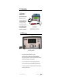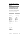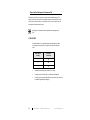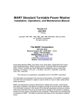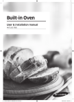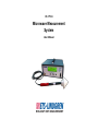
1
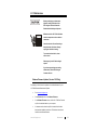
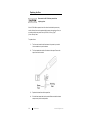
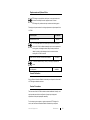
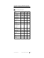
HI-1710A Microwave Measurement System User Manual ETS-Lindgren Inc. reserves the right to make changes to any product described herein in order to improve function, design, or for any other reason. Nothing contained herein shall constitute ETS-Lindgren Inc. assuming any liability whatsoever arising out of the application or use of any product or circuit described herein. ETS-Lindgren Inc. does not convey any license under its patent rights or the rights of others. © Copyright 2001–2014 by ETS-Lindgren Inc. All Rights Reserved. No part of this document may be copied by any means without written permission from ETS-Lindgren Inc. Trademarks used in this document: The ETS-Lindgren logo is a trademark of ETS-Lindgren Inc.; Avery is a registered trademark of Avery Dennison Corporation. Revision Record MANUAL,HI-1710A | Part #H-600094, Rev. E ii Revision Description Date A Initial Release May, 2001 B Added Alarm Out pin definitions; rebranding June, 2008 C Updated Error Analysis table in Specifications June, 2009 D Updated for v3.0 firmware release May, 2012 E Updated Menu Option Settings table in Filter (Response) command August, 2014 www.ets-lindgren.com This page intentionally left blank. www.ets-lindgren.com iii Table of Contents Notes, Cautions, and Warnings .............................................. vii General Safety Considerations ............................................. viii 1.0 Introduction .......................................................................... 9 HI-1710A Features ..................................................................................... 9 Standard Configuration ............................................................................. 10 Optional External Zero Receptacle ........................................................... 11 ETS-Lindgren Product Information Bulletin ............................................... 11 2.0 Maintenance ....................................................................... 13 Software/Firmware Updates (Version 3.XX Only) ...................................... 13 Replacing the Fuse ................................................................................... 14 Replacement and Optional Parts .............................................................. 15 Annual Calibration .................................................................................... 15 Service Procedures .................................................................................. 15 3.0 Specifications ..................................................................... 17 Electrical Specifications ............................................................................ 17 Physical Specifications ............................................................................. 18 RS-232 Specifications............................................................................... 18 Calibration ................................................................................................ 19 Power Cable ............................................................................................. 19 Error Analysis ........................................................................................... 20 4.0 Operation ............................................................................ 21 About Zeroing ........................................................................................... 21 Menu Navigation ....................................................................................... 22 Back Panel Controls and Connectors........................................................ 23 ZERO ............................................................................................... 23 ANALOG OUT .................................................................................. 23 ALARM OUT ..................................................................................... 24 RS-232 (Digital Input/Output) ............................................................ 24 Starting the HI-1710A ............................................................................... 25 Using the HI-1710A .................................................................................. 25 Connecting and Using the Zero Receptacle .............................................. 26 iv www.ets-lindgren.com 5.0 Menu Options, Settings, Command Set .......................... 27 Menu Options ........................................................................................... 27 Menu Option Settings and Command Set ................................................. 28 3 OR 4 DIGITS ................................................................................. 28 ABOUT (Version 3.XX Only) ............................................................. 29 ALARM SETPOINT........................................................................... 30 AUDIO .............................................................................................. 31 AUTO-RANGE .................................................................................. 31 BAUD RATE ..................................................................................... 32 CONTRAST ...................................................................................... 33 ECHO ............................................................................................... 33 FILTER (RESPONSE) ...................................................................... 34 PARAMETER SCREEN .................................................................... 35 PEAK HOLD ..................................................................................... 36 PRINT MODE ................................................................................... 37 RANGE ............................................................................................. 39 SELF TEST ...................................................................................... 40 STATUS ........................................................................................... 41 STIM ................................................................................................. 44 RESET.............................................................................................. 44 TEST ALARM ................................................................................... 45 VERSION (Firmware) – Version 3.XX Only ....................................... 45 ZERO ............................................................................................... 45 Factory Default Settings ............................................................................ 46 6.0 Theory of Operation........................................................... 47 Appendix A: Warranty ............................................................. 49 Appendix B: Error Messages .................................................. 51 Self-Test Error Messages ......................................................................... 51 Startup Error Messages ............................................................................ 52 REF C – OUTSIDE LIMIT ................................................................. 52 +5SUP C – OUTSIDE LIMIT ............................................................. 52 +8SUP C – OUTSIDE LIMIT ............................................................. 52 -8SUP C – OUTSIDE LIMIT .............................................................. 52 BIAS C – OUTSIDE LIMIT ................................................................ 53 STIM C – OUTSIDE LIMIT ................................................................ 53 www.ets-lindgren.com v Appendix C: Summary of RS-232 Command Set ................. 55 Appendix D: EC Declaration of Conformity .......................... 57 vi www.ets-lindgren.com Notes, Cautions, and Warnings Note: Denotes helpful information intended to provide tips for better use of the product. Caution: Denotes a hazard. Failure to follow instructions could result in minor personal injury and/or property damage. Included text gives proper procedures. Warning: Denotes a hazard. Failure to follow instructions could result in SEVERE personal injury and/or property damage. Included text gives proper procedures. See the ETS-Lindgren Product Information Bulletin for safety, regulatory, and other product marking information. www.ets-lindgren.com vii General Safety Considerations Safety Symbol Definition Warning: This is a Safety Class I product (provided with a protective earthing ground incorporated in the power cord). The mains plus shall only be inserted in a socket outlet provided with a protective earth contact. Any interruption of the protective conductor, inside or outside the instrument, is likely to make the instrument dangerous. Intentional interruption is prohibited. DO NOT defeat the earthgrounding protection by using an extension cable, power cable, or autotransformer without a protective ground conductor. Caution: This instrument is shipped with a three-wire power cable, in accordance with international safety standards. When connected to an appropriate power line outlet, this cable grounds the instrument cabinet. Warning: For indoor use only, do not expose to rain. viii www.ets-lindgren.com 1.0 Introduction The ETS-Lindgren Holaday HI-1710A Microwave Measurement System combines the proven and reliable diode sensing technology of the ETS-Lindgren Holaday Microwave Survey Meters with the digital processing techniques developed for automatic oven scanning. HI-1710A with HI-2623 Microwave Oven Probe HI-1710A Features HI-1710A Front Panel Provides time response characteristics, or filters: raw (Version 3.XX only), fast, and slow. These allow standard hand scan measurements, as well as the potential for faster scanning similar to that of automated scanning systems. The unit is shielded with the necessary isolating and attenuating devices to provide immunity to stray leakage of microwave energy. The circuitry is powered by a regulated supply with normal industrial transient protection devices. www.ets-lindgren.com Introduction 9 The diode detection array of eight hot carrier diodes is housed in the large end of the plastic probe assembly. This antenna array has the unique feature of being able to sum microwave electric fields of any plane perpendicular to the axis of the probe. The antenna lobe is also very broad, making it easy to use when measuring leakage around an oven door. The cone spacer is designed to provide 5-cm spacing (as required by the CDRH performance standard) from the tip of the probe cone to the center of the array. The shape of the cone provides minimum perturbation of the electric field impinging on the diode array. The probe is attached permanently to the preamplifier assembly by a 9-ft shielded cable. Each detection probe and amplifier assembly is calibrated as a unit and can be used interchangeably with any HI-1710A readout. The digital indicator reads to two or three decimal places from 0 to 9.999 mW/cm2. Temporary over exposure to microwave fields up to 2000 mW/cm2 will not cause probe burnout or damage the instrument or the calibration. Either auto-range or four ranges with full-scale indications of 1, 2, 5, and 10 mW/cm2 can be selected from the front panel or with a remote serial port command. Selecting the range determines the full-scale setting of the bar graph display located below the digital readout for a continuous analog indication of the measured leakage level. The audio alarm circuit can be set to any level up to 9.99 mW/cm2. When the level of the microwave leakage exceeds the pre-selected value the audio alarm will sound if the audio is enabled, alerting the operator that the chosen level has been exceeded. For more information about the alarm, see page 30. Standard Configuration 10 HI-1710A Microwave Measurement System HI-2623 Microwave Oven Probe Power cable Introduction www.ets-lindgren.com Optional External Zero Receptacle The external zero receptacle will help shield the probe from stray RF fields while being zeroed. Additionally, in high-volume testing situations, the zero receptacle can reduce wear on the ZERO button located on the HI-1710A front panel. The zero receptacle ships with a 10-foot cable. For ordering information, see Replacement and Optional Parts on page 15. For information on using the zero receptacle, see Connecting and Using the Zero Receptacle on page 26. ETS-Lindgren Product Information Bulletin See the ETS-Lindgren Product Information Bulletin included with your shipment for the following: Warranty information Safety, regulatory, and other product marking information Steps to receive your shipment Steps to return a component for service ETS-Lindgren calibration service ETS-Lindgren contact information www.ets-lindgren.com Introduction 11 This page intentionally left blank. 12 Introduction www.ets-lindgren.com 2.0 Maintenance Before performing any maintenance, follow the safety information in the ETS-Lindgren Product Information Bulletin included with your shipment. WARRANTY Maintenance of the HI-1710A is limited to external components such as cables or connectors. Clean the exterior of the cabinet using a damp cloth and mild cleaner. Always unplug the unit before cleaning. To prevent electrical shock, do not remove cover. Warranty may be void if the housing is opened. If you have any questions concerning maintenance, contact ETS-Lindgren Customer Service. Software/Firmware Updates (Version 3.XX Only) Periodically you should check for updates to the software/firmware for your HI-1710A Microwave Measurement System. Go to www.ets-lindgren.com. On the Resources menu, click Software/Firmware. In the Software/Firmware column, look for HI-1710A files. Save the zip file to the desired location on your computer. In the same section where the zip file is located, click the link to download the installation instructions. Follow those instructions to install the new software/firmware. www.ets-lindgren.com Maintenance 13 Replacing the Fuse Disconnect the HI-1710A from power before replacing a fuse. If the HI-1710A fails to operate, check for a blown fuse inside the power entry module. A blown fuse must be replaced with the same value and type of fuse, or an unsafe condition may result. Use only 250 Volt, 1.0 Amp, Type T (5 mm x 20 mm) fuses. To replace a fuse: 14 1. Two fuses are located in the fuse drawer in the power input module. Use a screwdriver to open the drawer. 2. The fuse towards the outside of the drawer is the spare. Remove the spare fuse from the module. 3. Replace the blown fuse with the spare fuse. 4. Slide the fuse drawer back into the module. Make sure that the drawer snaps securely into its locked position. Maintenance www.ets-lindgren.com Replacement and Optional Parts ETS-Lindgren may substitute a similar part or new part number with the same functionality for another part/part number. Contact ETS-Lindgren for questions about part numbers and ordering parts. Following are the part numbers for ordering replacement or optional parts for the HI-1710A. Part Description Microwave Oven Probe Part Number HI-2623 The HI-2623 Microwave Oven Probe may be used interchangeably with the HI-1710A. A calibrated assembly may be used to replace the existing probe, eliminating downtime. Many service problems are related to probe or cable damage and can be corrected without sending the HI-1710A for service. Spacer Cone Kit—Includes 10 cones and 20 shields. H-540013 To maintain stated accuracy, use only ETS-Lindgren replacement cones. Zero Receptacle H-490930 Annual Calibration See the Product Information Bulletin included with your shipment for information on ETS-Lindgren calibration services. Service Procedures The inner case of the HI-1710A is sealed to maintain calibration. Normally, user repair operations are limited to verification of proper input voltage and replacement of the probe/preamplifier assembly. For the steps to return a system or system component to ETS-Lindgren for service, see the Product Information Bulletin included with your shipment. www.ets-lindgren.com Maintenance 15 This page intentionally left blank. 16 Maintenance www.ets-lindgren.com 3.0 Specifications Electrical Specifications Ranges: Four ranges: 0–1, 0–2, 0–5, and 0–10 mW/cm2 Response Characteristics: 0 to 90% of final value for step input: F0, Raw (Version 3.XX only)— unfiltered F1, Slow—less than three seconds F2, Fast—less than one second Maximum Power Density: 2.0 Watts/cm2 (2000 mW/cm2) Power Input: 100–240 VAC 0.8–0.4 A max 50/60 Hz Fuses: 250 Volt, 1.0 Amp, Type T (5 mm x 20 mm) Control Inputs: Zero—Dry switch closure to zero the HI-1710A RS-232—Standard 9-pin, 2-way communications input Control Outputs: Alarm Output—Form C contact; 24 V 1 Amp Analog Output—4 VDC max; 1 mA max RS-232— Standard 9-pin, 2-way communications output www.ets-lindgren.com Specifications 17 Environmental: Operating Temperature: 15°C–40°C Humidity: 5% to 95% relative humidity, non-condensing Physical Specifications Dimensions: Height: 127 mm (5.0 in) Width: 311 mm (12.25 in) Depth: 254 mm (10.0 in) Probe: Probe Length: 305 mm (12 in) Cable Length: 2.74 m (9 ft) Weight: 3.6 kg (8 lb) RS-232 Specifications Connector: Standard 9-pin, 2-way communications input/output Communications Protocol: 8 data bits, 1 stop bit, no parity, no flow control, 9600 baud (default) Pin Designations: Pin 2: Data received by HI-1710A from computer Pin 3: Data transmitted from HI-1710A to computer Pin 5: Ground 18 Specifications www.ets-lindgren.com Calibration Calibration: Calibrated at 2450 MHz for use in the ISM band Calibration is performed at a standard temperature of 75°F in an anechoic chamber, utilizing a slot radiator. A CW field is generated using a crystal-controlled solid state source. The power monitoring system is the HI-2795 Calibration Comparison System. The calibration field level is established using a reference survey meter with CDRH calibration correction factors. All ranges are calibrated at mid-scale. Power Cable The HI-1710A Microwave Measurement System is shipped with a three-wire power cable. When the cable is connected to an appropriate AC power source, it connects the chassis to earth ground. The type of power cable shipped with each HI-1710A depends on the country of destination. www.ets-lindgren.com Specifications 19 Error Analysis 1.0 mW/cm2 Absolute Calibration +0.30 dB Precision ±0.13 Linearity and AM response ±0.15 Frequency Response* ±0.04 Near field response ±0.29 Polarization* ±0.21 Pattern +0 / -0.11 Temperature +0.46 / -0.15 Supply Voltage ±0.01 RFI* ±0.01 Overload ±0.01 Drift* ±0.04 -1.068 / +1.568 dB * Values are combined in an RMS manner. 20 Specifications www.ets-lindgren.com 4.0 Operation Before connecting any components, follow the safety information in the ETS-Lindgren Product Information Bulletin included with your shipment. Do not use without spacer cone in place. About Zeroing Zeroing determines the offset value that will be subtracted from all subsequent measurements. RF must not be present in the vicinity of the probe when the zero switch is activated, or it will result in an inaccurate zero. There are three ways to zero a probe connected to the HI-1710A Microwave Measurement System: Press the ZERO button on the front panel. Send the serial port command Z. Attach an external device to the ZERO connector on the back panel. The zero will drift as the electronic circuitry and diodes warm up to normal operating temperature. There will also be small variations as the ambient temperature changes during the day. For these reasons, the zero point must be reset periodically. In addition, the bias and offset readings are checked against preset internal limits each time the zero switch is activated. If the limits are exceeded, an error message is displayed. Zeroing in a sufficiently high RF field or zeroing with the probe removed will also cause an error. These tests measure the performance characteristics of the probe and serve as failure indicators. www.ets-lindgren.com Operation 21 Menu Navigation HI-1710A Front Panel See Menu Options, Settings, and Command Set on page 27. 1. To display the menu, press any arrow button on the front of the HI-1710A. 2. Press the down arrow button to move the highlighted selection down one item at a time, and press the up arrow button to move the highlighted selection up one item at a time. 3. With the item you want to change highlighted, press the left/right arrow button to move to the settings for that item. 4. Press the up or down arrow buttons to scroll through the available settings for the highlighted item. 5. Highlight the desired setting and then release the buttons. After approximately three to four seconds the display will return to the main screen with the new/highlighted settings in effect. (Version 3.XX only) Press the ZERO button once on the front of the HI-1710A to go back one level in the menu. Do not to press the button more than once or you will zero the probe. 22 Operation www.ets-lindgren.com Back Panel Controls and Connectors HI-1710A Back Panel ZERO Can be used to attach an external device to the ZERO connector. See About Zeroing on page 21 for more information on the zero function. ANALOG OUT This analog output BNC connector is a DC voltage varying from 0 to 4 volts proportional to the full scale range setting. For example, with the instrument on range 2 (0–2 mW/cm2), a leakage value of 2 mW/cm2 will have an analog signal of 4 VDC and a 1 mW/cm2 value will have a signal of 2 VDC. On range 4 (0–10 mW/cm2), the 4 VDC analog output signal will indicate 10 mW/cm2. The resistance of the external load connected to the analog output receptacle should not be less than 5000 ohms. www.ets-lindgren.com Operation 23 ALARM OUT Pin Definition 1 NC 2 NC 3 Normal 4 Common 5 Alarm RS-232 (DIGITAL INPUT/OUTPUT) This two-way, standard 9-pin RS-232 serial data port is used to connect external devices. These external devices can monitor and/or control the HI-1710A. All functions normally accessed by the touch switch inputs can be controlled externally and all data normally displayed can be transmitted through the serial port. This is accomplished using a simple command structure of ASCII character codes and a controller such as a personal computer or a video display terminal (VDT). See Appendix C on page 55 for a summary of commands. The default mode of the HI-1710A generates a formatted test summary. When on, the default conditions are 8 data bits, 1 stop bit, no parity, and no flow control. The HI-1710A is set up at the factory for 9600 baud. This makes it possible to connect a monitoring device such as a VDT or printer. The baud rate of the serial port can be changed either through the HI-1710A menu options or by an external command through the RS-232 serial port. 24 Operation www.ets-lindgren.com Starting the HI-1710A 1. With the power off, attach the HI-2623 Microwave Oven Probe to the probe connector on the front of the HI-1710A. Insert the connector so that the locating screw is facing upward. 2. Connect the HI-1710A to AC power. 3. Turn on the power switch on the front of the HI-1710A. The screen will display the firmware version and additional ETS-Lindgren information. During this time a series of self-tests are performed; when the self-tests are complete, the probe is ready to be zeroed. 4. Place the probe in a zero field environment, and then press ZERO on the front of the HI-1710A. When zeroing is complete, the HI-1710A is ready for operation. Using the HI-1710A Check the probe spacer cone for damage, discoloration, or contamination. Accuracy may be affected by cone wear or damage or by contamination by metallic particles which may become imbedded in the cone. If necessary, replace the cone. See Replacement and Optional Parts on page 15 for part numbers. 1. Allow the HI-1710A to warm up for at least 10 minutes. 2. Select the operating settings for the test needs. For normal tests or a beginning point, use the default conditions. To select settings, see Menu Options, Settings, and Command Set on page 27. 3. Zero the probe before beginning the test. With the oven operating with a suitable load, move the probe across the oven surfaces, keeping the probe axis (handle) perpendicular to the potential leak area. Hold the probe by the red handle to avoid potential interference. Keep other parts of the body and the probe cord away from the immediate vicinity of the probe head. www.ets-lindgren.com Operation 25 The analog bar graph display may be used to determine areas of highest leakage. In the normal mode (not Peak Hold) the bar graph display will track the displayed digital value and respond to the filtered RF signal. When the instrument is operated in the Peak Hold mode, the bar graph display is not filtered and responds very rapidly to changes in RF intensity. The Peak Hold mode may be used while scanning to capture the area of highest leakage, while the bar graph will continuously display instantaneous variations in leakage. Changing the filter selection to FAST will decrease the response time of the system. This will more effectively show the effect of rapid variations in RF levels due to mode stirrers or other modulating devices. In both the SLOW and FAST filter positions, the response time meets the CDRH requirement for RF measuring instrument response times while the SLOW response characteristic provides maximum smoothing of RF variations. After the test is completed and the RF reading recorded, zero the HI-1710A again before the next test. The zero point may gradually drift over long periods. Re-zero before beginning a test. Connecting and Using the Zero Receptacle The zero receptacle should be located in an area that is relatively free of significant RF fields. The fields near the zero receptacle should be checked periodically to confirm that no significant stray fields are present. 1. Attach the cable to the ZERO BNC connector located on the back of the HI-1710A. 2. Attach the other end of the cable to the connector on the side of the zero receptacle. The zero receptacle is most often used with Peak Hold mode. When scanning an oven in Peak Hold, the highest reading is displayed on the HI-1710A. When the probe is inserted into the zero receptacle, the RF reading is sent to the RS-232 serial port for automatic data collection and the probe is zeroed. For manual data recording, the RF reading must be recorded before the probe is inserted into the zero receptacle. 26 Operation www.ets-lindgren.com 5.0 Menu Options, Settings, Command Set Menu Options Use the arrow buttons on the front of the HI-1710A to navigate the menu. See Menu Navigation on page 22 for a description of the arrow buttons. Following are the menu options and command set for the HI-1710A Microwave Measurement System; each is described in the following pages. Menu Option & Serial Port Command Serial Port Command Only AUTO-RANGE—see page 31 ** 3 OR 4 DIGITS—see page 28 ABOUT—see page 29 ** Auto-Range is also a setting ALARM SETPOINT—see page 30 in the RANGE menu option; AUDIO—see page 31 see page 39. BAUD RATE—see page 32 ECHO—see page 33 CONTRAST—see page 33 STATUS—see page 41 FILTER (RESPONSE)—see page 34 VERSION (firmware)—see page 45 PARAMETER SCREEN—see page 35 ZERO—see page 45 PEAK HOLD—see page 36 PRINT MODE—see page 37 RANGE—see page 39 RESET—see page 44 SELF TEST—see page 40 STIM—see page 44 TEST ALARM—see page 45 www.ets-lindgren.com Menu Options, Settings, Command Set 27 Menu Option Settings and Command Set Following is a description of each menu option and the available settings. The majority of the menu options have an equivalent serial port command that can be used to set or retrieve a status; in a few cases, there is no menu option, and only the serial port command can be used. All serial port commands must be completed with a carriage return (CR). 3 OR 4 DIGITS Specifies whether 3 or 4 digits will display; includes digit to the left of the decimal point and either 2 or 3 digits to the right of the decimal point. 28 Menu Option Setting Serial Port Command 3 D3 4 D4 — D? All numeric commands return a total of 3 or 4 digits. In 3-digit mode, the fourth digit is rounded and not displayed. In 4-digit mode, some least significant bit noise will be seen, resulting in the least significant digit changing. Menu Options, Settings, Command Set www.ets-lindgren.com ABOUT (VERSION 3.XX ONLY) Displays/returns the installed firmware version and other ETS-Lindgren and system information. When ON is selected, the information will display for approximately 10 seconds. Menu Option Setting Serial Port Command OFF — ON — — *IDN? www.ets-lindgren.com Menu Options, Settings, Command Set 29 ALARM SETPOINT Sets a level after which an alarm will sound to indicate that the measured leakage has exceeded the level. The alarm will sound only if the audio is turned on. To turn on the alarm, see Audio on page 31. Menu Option Setting Serial Port Command XX.XX T#### — T? Where #### is a value from 0 to 9999 in mW/cm2. For example, 5000 is 5.0 mW/cm2, 5 is 0.005 mW/cm2, and so on. Each press of the up/down arrow button will raise/lower the setting by 0.01 for the first ten presses (9.99, 9.98, 9.97, and so on), by 0.10 for the next ten presses (9.89, 9.79, 9.69, and so on), and by 1.00 for the remaining presses (8.89, 7.89, 6.89, and so on). Any time a change in direction is made up or down, the change increment begins at 0.01. The alarm will sound only when the displayed RF value exceeds the alarm set point. For example, if the alarm is set at 4.99 mW/cm2, the alarm will only sound when the displayed RF level is 5.00 or greater. Once the RF level decreases below the alarm set point, the alarm will turn off. 30 Menu Options, Settings, Command Set www.ets-lindgren.com AUDIO Turns on the audible alarm indicator, which will sound to indicate that the measured leakage has exceeded a preset level (alarm set point). Although the alarm set point may be specified, the alarm will not sound unless the audio is turned on. For set point information, see page 30. Menu Option Setting Serial Port Command OFF Q0 ON Q1 — Q? AUTO-RANGE When set to auto-range, the best range for each measuring condition will automatically be selected. Menu Option Setting Serial Port Command Function — A0 OFF — A1 ON — A? Retrieve status The auto-range setting only affects the bar graph display and the analog output. When in Peak Hold with the range set to AUTO, the range will change as the field strength increases; it will remain in the range that shows the highest peak value until the ZERO button is pressed. This is so the peak value can be displayed on the bar graph. When the ZERO button is pressed with no field present, the range will revert back to the lowest (1 mW/cm2). www.ets-lindgren.com Menu Options, Settings, Command Set 31 BAUD RATE Sets the communication rate between the HI-1710A and an external device. 32 Menu Option Setting Serial Port Command 57600 B57 19200 B19 9600 B96 4800 B48 2400 B24 1200 B12 600 B60 300 B30 — B? After the baud rate is changed on the HI-1710A, it also must be changed on the external device. When baud rates are incorrectly set, a video display terminal (VDT) may display nonsense or non-printing characters. The baud rate is changed immediately when a B command is sent. The baud rate setting is saved in memory when the power is turned off. Menu Options, Settings, Command Set www.ets-lindgren.com CONTRAST Increase the value to darken the display or decrease it to lighten the display. Menu Option Setting Serial Port Command 0–8 C0–8 — C? ECHO When echo is on, keyboard entries on the VDT will also be displayed on the VDT screen. Menu Option Setting Serial Port Command OFF E0 ON E1 — E? The echo mode can be used when marginal transmission conditions exist or when the HI-1710A is connected to a full duplex terminal that requires the characters be re-transmitted. www.ets-lindgren.com Menu Options, Settings, Command Set 33 FILTER (RESPONSE) Digital filtering, or response times, changes the response to rapidly-changing RF or leakage levels; see Theory of Operation on page 47 for more information. 34 Menu Option Setting Serial Port Command RAW (Version 3.XX only) F0 SLOW F1 FAST F2 — F? RAW (Version 3.XX only)—Unfiltered. SLOW—Equivalent to slow response mode on analog meters. SLOW is the default setting, and is used for most hand-scanning of microwave ovens. It responds more slowly to rapidly-changing RF or leakage levels and tends to average the response to peak levels caused by oven mode stirring devices. This is designed to meet the CDRH requirement that an instrument respond to a step CW microwave input to 90% of its steady state reading within a maximum of three seconds, while still providing maximum smoothing of RF peaks. FAST—Equivalent to fast response mode on analog meters. It is used to observe rapid variations in RF leakage and to evaluate the effect of stirrer modulation on leakage. Menu Options, Settings, Command Set www.ets-lindgren.com PARAMETER SCREEN Displays system board voltages and probe voltages and offsets. Change the setting to ON, and exit the menu to display the parameter screen. Press the ZERO button to escape the parameter screen. Menu Option Setting Serial Port Command OFF — ON — Sample Parameter Screen RF—Probe RF level currently detected. BIAS—Probe bias reading; value should be between 0.30 and 0.40 volts. REF—Power supply reference voltage; value should be between 1.22 and 1.26 volts. +5SUP—Power supply +5 voltage; value should be between 4.75 and 5.25 volts. +8SUP—Power supply +8 voltage; value should be between 7.60 and 8.40 volts. -8SUP—Power supply -8 voltage; value should be between -7.92 and -8.08 volts. OFST—Probe offset reading; value should be between 0.02 and 0.40 mW (0.005 and 0.100 volts). www.ets-lindgren.com Menu Options, Settings, Command Set 35 STIM—Applies and displays a DC voltage to the input of the RF signal circuitry; value should be between 2.44 and 4.88. Readings outside this range indicate a fault in the HI-2623 probe/preamplifier. TEST—Voltage at the analog output jack; value should be between 3.80 and 4.20 volts. If an error occurs in any of the parameter readings, the parameter screen displays and the erroneous reading flashes. Turn the HI-1710A off, correct the problem, and then turn it on again. PEAK HOLD Captures and holds the highest leakage reading displayed. 36 Menu Option Setting Serial Port Command ON P1 OFF P0 — P? While in Peak Hold the bar graph on the display shows the current instantaneous RF reading, without filtering. A bar graph segment remains lit to indicate the relative location of the peak reading. The bar graph display responds very rapidly and will show stirrer/turntable modulation as well as minima and maxima of leakage around the microwave oven periphery. Because of the fast, unfiltered, response of the bar graph display, the digital peak reading may lag behind the bar graph indication, depending on the filter factor chosen. When the instantaneous RF indication on the bar graph display is greater than the reading on the digital display, the bar graph segment proportional to the digital reading is unlit. In this way the Peak Hold mode of the meter can be used to observe the effects of the various digital filters on fast changing RF inputs. In the normal mode (not Peak Hold), the bar graph display follows the filtered display reading. Menu Options, Settings, Command Set www.ets-lindgren.com PRINT MODE There are four modes that specify the content and length of the information provided during testing. See page 42 for the status message formats for modes 0, 1, and 2, and page 43 for mode 3. Menu Option Setting Serial Port Command 0 M0 1 M1 2 M2 3 M3 — M? Mode 0—Print mode off. Select this mode when no automatic output from the HI-1710A is needed; for example, when all output is specifically requested by the controller. This mode might be chosen in a fully-automatic test system where the external device requests the measurement, data gathering, and the zeroing of the meter. Status messages are transmitted in the same form as in mode 2, but no message is transmitted by the HI-1710A when the zero command is received. Mode 1—Prints continuous reading. In this mode the HI-1710A continually sends the RF reading through the RS-232 serial port. Data is transmitted at a high rate and can only be used at baud rates of 4800 and above; data is sent at a rate of 45 Hz, the same rate at which the probe is sampled. The controlling device must be able to receive a serially-transmitted 4-digit number 45 times a second. This mode might be used in the laboratory to investigate the effects of different filter constants and scan rates. The output from the HI-1710A is a three- or four-digit ASCII string in the format X.XX or X.XXX. www.ets-lindgren.com Menu Options, Settings, Command Set 37 Mode 2—Prints summary ticket. This is the default mode. The HI-1710A sends a pre-formatted summary report through the RS-232 serial port each time the probe is zeroed. This is most useful when using Peak Hold mode. With this configuration, a serial input printer set up to print adhesive-backed labels can be connected to the RS-232 serial port. After scanning an oven, the meter is zeroed. On zeroing, a ticket is printed with the maximum leakage observed as well as several system test parameters. The output is formatted for a standard 3 1/2-in x 15/16-in label (for example, Avery® label 4013). Line feed characters are transmitted following the formatted data to advance one additional label space with each formatted output. By printing the report on every other label, the labels can be removed from the backing more conveniently. Mode 3—Does not print summary ticket when zeroed. Changes the output format of the status messages S0–S8. The transmitted summary messages are shortened for easier adaptation to a computer interface program. The zero command does not transmit a formatted report as in mode 2. In mode 3 the transmitted status messages end with only a carriage return terminator (CR). In modes 0, 1, and 2, the messages end with a carriage return and a line feed (CR/LF). 38 Menu Options, Settings, Command Set www.ets-lindgren.com RANGE The range determines the full-scale setting of the bar graph display located on the front panel digital readout for a continuous analog indication of the measured leakage level. The four ranges have full-scale indications of 1, 2, 5, and 10 mW/cm2; the digital display will always indicate any value between 0 and 9.999 mW/cm2. When set to auto-range, the best range for each measuring condition will automatically be selected. For more information on auto-range, see page 31. Menu Option Setting Serial Port Command AUTO A1 0-1mW R1 0-2mW R2 0-5mW R3 0-10mw R4 — R? With no RF input, the instrument will shift to the 0–1 mW/cm2 scale. When the displayed value exceeds 95% of full scale, the next higher scale is automatically selected. While the digital reading will always indicate any value up to 9.999 mW/cm2, the bar graph display will change to reflect the correct percentage of the newly-selected range. When the displayed value drops below 30% of full scale, the next lower range is selected. If the unfiltered RF signal from the probe exceeds 20 mW/cm2 or the filtered RF signal exceeds 10 mW/cm2, the HI-1710A will indicate an over range condition by sounding a continuous beep. The over range condition will remain until the filtered RF signal drops below 10 mW/cm2. www.ets-lindgren.com Menu Options, Settings, Command Set 39 SELF TEST Performs a series of self-tests; when the self-tests are complete, the probe is ready to be zeroed. 40 Menu Option Setting Serial Port Command SELF TEST ST After successful completion of the self-test, the HI-1710A sends SELF TEST PASSED message, plus three blank lines. If the self-test fails, the parameter screen displays. Press the ZERO button to initiate another self-test. If an error occurs, turn off the HI-1710A, correct the error, and then turn on the HI-1710A. Menu Options, Settings, Command Set www.ets-lindgren.com STATUS Checks status for the following: Menu Option Serial Port Command — S0 Send System Status — S1 Send Alarm Set Point — S2 Send Range Number — S3 Send Filter Number — S4 Send Bias Voltage — S5 Send Offset — S6 Send STIM Value — S7 Send Power Supply Voltages — S8 Send RF Reading* — S9 Send Non-Filtered RF Reading* (Version 3.XX only) Function *(Version 3.XX only) In Peak Hold mode S8 will return peak RF value. For the current RF reading, use S9. The format of information returned depends on the current print mode. See page 42 for the status message formats for print modes 0, 1, and 2, and page 43 for print mode 3. For more information on print modes, see page 37. www.ets-lindgren.com Menu Options, Settings, Command Set 41 Print Modes 0, 1, 2 S0 DIGITS=V/AUTO RNG WWW/PEAK HOLD XXX/YY RNG/PRINT MODE Z Where: V is 3 or 4 WWW is ON or OFF XXX is ON or OFF YY is IN or OUT Z is 0,1, or 2 S1 ALARM --- X.XX or X.XXX S2 SCALE --- X S3 FILTER --- XXXX Where XXXX is RAW (Version 3.XX only), FAST, or SLOW S4 BIAS --- X.XX or X.XXX S5 OFFSET --- X.XX or X.XXX S6 STIM --- X.XX or X.XXX S7 REFERENCE --- X.XXX 5 VOLTS --- X.XXX 8 VOLTS --- X.XXX -8 VOLTS --- X.XXX S8 RDNG OK --- X.XX or X.XXX The RF value depends on the filter setting. S9 (Version 3.XX only) RDNG OK --- X.XX or X.XXX The RF value is raw/unfiltered. 42 Menu Options, Settings, Command Set www.ets-lindgren.com Print Mode 3 S0: XXXXX First digit—3 or 4 for number of digits displayed and transmitted Second digit—0 or 1 for auto-range off or on Third digit—0 or 1 for Peak Hold off or on Fourth digit—0 or 1 for in range or over range Fifth digit—0, 1, 2, or 3 for operating mode S1: X.XX Alarm trigger point (X.XXX in four-digit mode) S2: X Range number 1–4 S3: X 1 = F1 (Slow) S4: X.XXX Bias voltage (X.XXX in four-digit mode) S5: X.XXX Offset; milliwatts (X.XXX in four-digit mode) S6: X.XX STIM test value (X.XXX in four-digit mode) S7: X.XXX Reference voltage level X.XXX 5 volt power supply level X.XXX 8 volt power supply level X.XXX -8 volt power supply level S8: X.XX RF reading (X.XXX in four-digit mode) S9: X.XX (Version 3.XX only) Raw/unfiltered RF value (X.XXX in four-digit mode) www.ets-lindgren.com Menu Options, Settings, Command Set 43 STIM Performs a stimulus routine to verify that the probe is operational. Menu Option Setting Serial Port Command NO — YES S6 When activated, the HI-1710A will apply a DC voltage to the input of the RF signal. The STIM value should be between 2.44 and 4.88. Readings outside this range indicate a fault in the HI-2623 probe/preamplifier. RESET This will reset the HI-1710A to factory settings and overwrite any settings you changed. See Factory Default Settings on page 46 for more information. In addition to resetting the system to factory defaults, RESET performs the self-test sequence. 44 Menu Option Setting Serial Port Command NO — YES I Menu Options, Settings, Command Set www.ets-lindgren.com TEST ALARM Sets or resets the alarm relay located on the back panel of the HI-1710A. Menu Option Setting Serial Port Command ON — OFF — VERSION (FIRMWARE) – VERSION 3.XX ONLY Returns the version of installed firmware. Menu Option Setting Serial Port Command — VER? Format: X.XX ZERO Zeros the probe; performs the same function as pressing the ZERO button on the front panel. Menu Option Setting Serial Port Command — Z When the zero command is received and the RS-232 output is in mode 2 (default mode), a formatted output message is sent through the serial port and the probe is zeroed. The formatted message transmits the RF reading only when the front panel Peak Hold mode is ON. www.ets-lindgren.com Menu Options, Settings, Command Set 45 Factory Default Settings All settings are stored in memory. The last settings used will be restored each time the HI-1710A is turned off. RESET returns the HI-1710 to factory default settings. For more information on RESET, see page 44. When you receive the HI-1710A, it is configured with the following settings; these default settings can be used for normal production line testing. 46 3 or 4 Digits: 3 (two places to the right of the decimal) Alarm Set Point: 5.0 Audio Alarm: OFF Baud Rate: 9600 Display Contrast: 7 Filter (Response): Slow Peak Hold: OFF Print Mode: 2 Range: 0–1 mW/cm2 Menu Options, Settings, Command Set www.ets-lindgren.com 6.0 Theory of Operation The HI-1710A Microwave Measurement System uses a unique diode/dipole antenna sensor that is coupled with digital filtering techniques developed for Automatic Microwave Oven Scanner Systems. A radial array of eight antennas is located perpendicular to the axis of the probe handle. The electric field is detected by hot carrier diodes operating in the square law region. A negative voltage is applied to the cathode connection of the diodes to bias them in an optimum operating region. The bias is adjusted individually for each probe/preamplifier assembly. The diode signals are summed and input to two stages of amplification. The amplifying stages perform analog filtering to minimize external interference at 60 Hz. The analog output of the preamplifier is connected to one input of a seven channel analog-to-digital converter. The bias input is connected to another channel. Scaled values of the various power supply voltages are connected to the remaining inputs. The digital equivalent of the RF signal is input to the microprocessor. A software-implemented filter is used to condition the RF signal for most effective RF measurement. The filtering in the HI-1710A is accomplished by an integrating software filter. Sets of fixed filter parameters can be selected from the front panel of the HI-1710A. Selecting filter 1 (F1 / SLOW) results in a digital filter characteristic with a rise time 90% of less than three seconds. This response is equivalent to the SLOW response of the common analog microwave survey meter. Filter 2 (F2 / FAST) results in a digital filter characteristic with a rise time 90% of less than one second. The response of this filter is much faster and is equivalent to the FAST response of an analog survey meter. After filtering, the final leakage value is displayed as a 3- or 4-digit value. The microprocessor also performs the peak hold and alarm functions. In the Peak Hold mode, the bar graph display is driven without any digital filtering to display the real time variations in the RF level. In the Peak Hold mode, the highest reading sent to the digital display by the processor is held and continuously displayed until either a higher reading is transmitted or until the probe is zeroed. The peak value displayed is the value obtained after all filtering is accomplished. www.ets-lindgren.com Theory of Operation 47 When not in the Peak Hold mode, the bar graph display responds to the filtered signal as displayed. The system performs a series of self-tests at startup and each time the probe is zeroed. The bias voltage is measured to check for defective diodes and for a proper bias supply, and then the offset voltage of the array is measured. The offset voltage is the signal at the preamp output with the probe in a zero RF field. Limits on the offset voltage check for proper probe/preamplifier operation. A zero chamber option is available to minimize the RF present at the probe head during zeroing; see Zero Receptacle Option on page 11. A stimulus voltage is applied to the input of the first operational amplifier stage in the preamp. This signal is used to test the integrity of the RF signal path. The level of each of the four power supply outputs is tested on startup. If an error is detected, the parameter screen will be displayed with the erroneous value flashing. Upon zeroing, the self-test is repeated until all errors are corrected. 48 Theory of Operation www.ets-lindgren.com Appendix A: Warranty See the Product Information Bulletin included with your shipment for the complete ETS-Lindgren warranty for your HI-1710A Microwave Measurement System. DURATION OF WARRANTIES FOR HI-1710A All product warranties, except the warranty of title, and all remedies for warranty failures are limited to one year. Product Warranted Duration of Warranty Period HI-1710A Microwave Measurement System 1 Year www.ets-lindgren.com Warranty 49 This page intentionally left blank. 50 Warranty www.ets-lindgren.com Appendix B: Error Messages In any mode, an invalid command will produce the error message ENTRY ERROR -- PLEASE RETRY. Self-Test Error Messages The following error messages will be transmitted if during the self-test an out of specification condition is detected. BIAS OUTSIDE LIMIT REF OUTSIDE LIMIT +5SUP OUTSIDE LIMIT +8SUP OUTSIDE LIMIT -8SUP OUTSIDE LIMIT STIM OUTSIDE LIMIT www.ets-lindgren.com Error Messages 51 Startup Error Messages As part of the self-test performed on startup, a number of error messages can be displayed indicating operating problems. In addition, the offset and bias values of the probe are measured each time the probe is zeroed. If an erroneous reading is detected, the HI-1710A Microwave Measurement System will display the parameter screen and the erroneous reading will flash. A message will also be sent to the RS-232 port. Following is the action to be taken for each error. REF C – OUTSIDE LIMIT 1.24-volt supply low 1.24-volt supply high: The 1.24 volt reference to the A/D converter is beyond specification. Return for service if error message persists. +5SUP C – OUTSIDE LIMIT 5-volt supply low 5-volt supply high: The 5-volt logic supply is beyond specification. Voltage is not user-adjustable; return for repair. +8SUP C – OUTSIDE LIMIT 8-volt supply low 8-volt supply high: The 8-volt supply to the analog circuitry is beyond specification. Voltage is not user-adjustable; return for repair. -8SUP C – OUTSIDE LIMIT 52 -8-volt supply low -8-volt supply high: The negative 8-volt supply to the analog circuitry is beyond specification. Voltage is not user-adjustable; return for repair. Error Messages www.ets-lindgren.com BIAS C – OUTSIDE LIMIT Bias voltage low Bias voltage high: The probe bias voltage is beyond specification. Check the negative 8-volt supply level. If the supply voltage is within specification, the probe/preamplifier assembly should be replaced. If the bias voltage is still beyond specification, return for service. STIM C – OUTSIDE LIMIT STIM test low STIM test high: A fault exists in the RF signal processing path. Replace the probe/preamplifier assembly; if the error persists, return for service. www.ets-lindgren.com Error Messages 53 This page intentionally left blank. 54 Error Messages www.ets-lindgren.com Appendix C: Summary of RS-232 Command Set For a list of factory settings, see page 46. Function Command Range Default 3 or 4 digit display D# 3–4 3 Alarm trigger point T#### 0–9999 5000 Audio mode (1=ON) Q# 0–1 0 Auto-range (1=ON) A# 0–1 0 Baud rate B## 12–96 96 Echo (1=ON) E# 0–1 0 Filter (Response) number F# 0–2 1 I — — Peak Hold (1=ON) P# 0–1 0 Print mode M# 0–3 2 Range R# 1–4 1 Self-test ST — — Z — — (0 is available only in Version 3.XX) Re-initialize system (Reset) Zero meter www.ets-lindgren.com Summary of RS-232 Command Set 55 This page intentionally left blank. 56 Summary of RS-232 Command Set www.ets-lindgren.com Appendix D: EC Declaration of Conformity www.ets-lindgren.com EC Declaration of Conformity 57