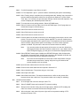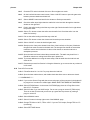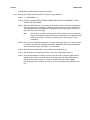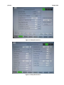
1
Chapter 6.24
Picosun Atomic Layer Deposition (ALD)
(picosun)
1.0
Equipment Purpose
1.1
2.0
4.0
Picosun ALD is a microprocessor controlled system that can atomically deposit a thin layer of
metal oxides, pure metals, and with an additional ammonia gas source (not connected at this time)
should be able to deposit metal nitrides. Metal oxide films grown by the ALD system are suitable
for gate dielectric, electroluminescent display insulators, capacitor dielectrics and MEMS
applications. Metal nitride thin films grown by the ALD could be used for diffusion barriers and
similar applications.
Materials Controls & Compatibility
2.1
3.0
(586)
Polymer material and other low temperature substrates must undergo process review before use
in picosun.
Applicable Documents
3.1
Picosun Sunale R-Series ALD tool User Manual (Copy in Office).
3.2
Material Safety Data Sheets for TMA and TTIP (Copies in Office and Lobby).
Definitions & Process Terminology
4.1
Atomic Layer Deposition: A self-limiting chemical process that uses metal precursors to coat an
atomically thin layer of metal or metal oxide or metal nitride film on the substrate surface.
4.2
Precursor: Source/s used in the ALD machine contains the desired metal for deposition. This
metal is bonded to a hydrophobic alkyl functional group such as Methyl (CH3), which will
ultimately leave a monolayer of metal oxide behind on the substrate (metal is reacted with water
vapor to form the metal oxide).
4.3
Source bottle: Up to three sources materials (precursors) can be provided in source bottles
installed on this particular ALD machine.
4.4
Injection: The precursor source bottle is pulsed open in specific intervals defined by the process
recipe. A carrier N2 gas will then delivers the precursor material to the reaction chamber.
4.5
Typical source materials for this system are:
4.6
4.5.1
TMA: Trimethylaluminum Al(CH3)3 is precursors used to deposit aluminum oxide.
4.5.2
TTIP: Titanium Tetrakis Isopropoxide, which supplies Ti source for the titanium oxide
process.
4.5.3
Other sources may be available as an alternative to above sources i.e. TiCl4 Titanium
Tetrachloride is a precursors used to deposit Titanium oxide. The number of sources that
can be installed on this tool are currently limited to three as per available source bottles
(hardware limited) on this tool.
hPa: Hectopascal – (1 hPa = 0.75006375541921 Torr)
picosun
5.0
6.0
Chapter 6.24
Safety
5.1
Follow all the NanoLab general safety rules.
5.2
Source gas: The system uses highly reactive source gases, great care must be taken when
source bottles are changed. Also, the source temperature needs to be lowered to room
temperature, before changing the source.
5.3
Chemical Hazard: Do not vent the chamber before purging process is finished. Please note
chemicals and their vapor used in this system are highly flammable and toxic. Any suspected
leak/s in the system needs to immediately be reported on the WAND.
5.4
Emergency shutdown: In case of an emergency, shut down the whole system by pressing the red
emergency button on the machine.
Process Data
6.1
Process Monitor (SPC): Available on MercuryWeb (Date TBD)
6.2
7.0
Available Processes, Gases, Process Notes
7.1
System Description
7.1.1
System Components: Picosun ALD system comprised of the Oxford wafer loader station,
deposition chamber, a source cabinet with the electronics and MFCs associated with it,
all of which are controlled by the ALD software installed on a user-friendly Select panel
controller (PLC).
7.1.2
Precursor Sources: There are currently three types of source bottle available on this
system designed to address different precursor materials at specific vapor pressure
ranges.
7.1.2.1
Source A: Liquid source with high vapor pressures above 10 mbar can be used
in this source bottle. Several source materials including the TMA (current
source) can be used in this source bottle.
7.1.2.2
Source B: Pico Solid source bottle at this station can be used for liquid or solid
sources with vapor pressures above 1mbar at temperatures less than 200°C.
Several source materials including the TTIP (current source) can be used in
this source bottle.
7.1.2.3
Source C: This source has the same design as source A, however, it is
currently dedicated to DI water as an oxidizing agent for metal oxide processes.
Note:
7.1.3
7.2
Other oxidizing agent such as; Ozone (requires additional ozone
generator) or Nitrous oxide (N20) or Hydrogen Peroxide (H2O2) in
water can be used in these type of ALD systems, however, we are
not currently set up with any of them.
MFCs: There are 4 MFCs available on the system, three of which are used for the
sources and one for the intermediate space N2.
System Control Description
7.2.1
The main control of ALD is a PLC based system with Select screen user interface. The
operations are divided into seven main pages which can be accessed by Selecting
picosun
Chapter 6.24
graphic buttons on the bottom portion of the display screen. Some of the pages contain
sub-pages. The functions of these main pages are described below:
7.2.2
PI CHART – Displays the system conditions, including temperatures, pressures, gas
flows and etc.
7.2.3
RECIPE – Used to load, edit, and save process recipes.
7.2.4
DEPOSIT – Used to start, stop, and abort a process run. It also displays the schematics
of process steps.
7.2.4.1
The DEPOSIT page contains a schematic drawing of the process flow. Each
circle stands for a process step. The highlighted one stands for the current
process step being executed.
7.2.4.2
There are two circles with capital “M” in their center, each representing a step
that needs lab member’s attention: First one to open the source valves before
deposition. Second one to close the source valves after the deposition.
7.2.4.3
In the center of the page, there are several colored rectangular boxes that
stand for process conditions. Red means a process condition is not satisfied.
Green means the process is ok to run.
7.2.5
ACTIONS – Contains some operation sequences used for routine system maintenance,
e.g. source line purge.
7.2.6
MANUAL – Used to operate some system components manually, e.g. open/close valves,
set chamber/source temperatures, set purge gas flows.
7.2.7
TRENDS – Used to view the charts of all the process parameters.
7.2.8
SETTINGS – Used to set system settings. Also used to log out the system.
7.2.9
BACK – Used to go back to previous control page.
Note:
In this manual, all the above main control buttons, displayed on the bottom of
the Select screen, are in bold and capital case. All the other control buttons
on each control page are bold, with only the first letter capitalized.
7.2.10 The wafer elevator and load lock gate valve are controlled via another small Select
screen control located on the lower shelf under the main Select screen. It is used, along
with two other manual valves, for wafer loading/unloading operations. There are four
Select screen buttons:
7.2.11 <VALVE> - Used to open or close the gate valve between the process chamber and the
load lock.
7.2.12 <HOME> - Used to home the wafer elevator and lift wafer up from process chamber for
unloading.
7.2.13 <Z1> - Used to move the elevator to intermediate position when pushing/pulling the load
lock rod.
7.2.14 <Z2> - Used to lower the elevator to the process position. It also closes the process
chamber.
Note:
7.3
Available Sources
In this manual, all the buttons for load lock/elevator control are bounded by <>
to avoid confusion with the main process control buttons.
picosun
7.4
7.5
7.6
Chapter 6.24
7.3.1
TMA: Trimethylaluminum Al(CH3)3, which supplies aluminum source for the aluminum
oxide process. (Source A)
7.3.2
TTIP: Titanium Tetrakis Isopropoxide, which supplies Ti source for the titanium oxide
process. (Source B, a heated source, process temperature 80°C )
7.3.3
DI Water: DI water vapor acts as oxidation agent. (Source C)
Available Recipes
Material
Precursor
Nanolab Inventoried and
replenished
Deposition Rate
Al2O3
TMA
Standard Process – Supported
and Replenished
~1 Å/Cycle
TiO2
TTIP
Supported Process – Supported
and Replenished
0.25 Å/Cycle
Process Notes
7.5.1
Samples with photoresist are not allowed in the Picosun ALD system.
7.5.2
The process chamber can accommodate one 6” or one 4” wafer at a time. Many small
samples can be loaded at a time on a 6” packet wafer, which can be checked out from
the office. Please note the ALD deposition only goes on the topside of the sample.
7.5.3
Take extra care not to crash the elevator or the gate valve in the system, as it does not
have all the necessary sensors for a fully automated operation.
Equipment Acceptable Parameter Window
7.6.1
Chamber Temperature: 150 – 350 C
7.6.2
Number of cycles: Up to 2000
7.6.3
Exceeding these limits requires staff approval
picosun
8.0
Chapter 6.24
Equipment Operation
8.1
Login Procedure
8.1.1
8.2
8.3
Select the Login button, and enter the password using the graphic keyboard. The
password, which is case sensitive, is given only to qualified lab members. Select the PI
button at the bottom of the page to go to PI Chart screen shown in Figure 1.
System Check
8.2.1
Go to PI CHART page.
8.2.2
Set the source purge nitrogen flows to 150 sccm
8.2.3
Set the chamber purge flow to 300 sccm.
8.2.4
Set chamber temperature to 100°C and the source to room temperature.
8.2.5
Check chamber pressure: Should be ~10 hPa.
8.2.6
Move elevator to <Z2>.
8.2.7
Check parameters on mercury to determine last deposition material.
8.2.8
If material deposited immediately prior differs from material being deposited in current run,
run dummy run for 100nm of deposition to ensure there is no flaking. (~200 cycles)
Loading Recipe
8.3.1
Go to the RECIPE screen.
8.3.2
Select Open Recipe button.
8.3.3
Select either the Al2O3 or TiO2 recipe.
Note:
If you do not see these two recipe options, Select Change Directory button, and
change the active directory to “STANDARD”, then repeat recipe loading.
The source type is defined in the recipe. Without loading the recipe, the source
temperature cannot be set.
8.4
Set Chamber/Source Temperature
8.4.1
Select MANUAL button
8.4.2
Select 3/3 button on the top right of the MANUAL page (Figure. 2).
8.4.3
Set the chamber/source temperature as the following table:
8.4.4
Recipe
Chamber
Heater
TE1 Max
Chamber
Temp
TE2
Source
Heater
TE21 Max
Source
Temp
TE20
Al2O3
450°C
300°C
NA
NA
TiO2
450°C
275°C
100°C
80°C
It takes 1.5 hours for the chamber temperature to stabilize at set point. After the chamber
temperature stabilizes, set TE1 Max to 400°C for better temperature control.
Note:
You can set TE1 to 500°C to shorten the chamber temperature time. But you
need to change TE1 to 400°C when the chamber temperature reaches 20°C
below set point. Otherwise, the chamber temperature will over shoot and it
picosun
Chapter 6.24
takes even longer time to cool down to set point. Do not set TE1 above 500°C
or you may damage the chamber.
8.5
Loading Wafer Into the Load Lock
8.5.1
Close the load lock gate valve (<VALVE> should read closed)
8.5.2
Slowly turn the 3-way valve located in the front of the load lock to the left (vent).
Note:
8.5.3
Open the load lock lid and load your wafer in.
Note:
8.6
Watch the nitrogen flow meter mounted on the back wall (make sure to vent
slowly). The nitrogen flow should not exceed the maximum mark to avoid
turbulence. It takes a few minutes to vent the load lock to atmosphere pressure.
On the wafer fork, there are two indent positions, for 6” and 4” wafer.
Samples/wafers of other sizes have to be put on a 6” pocket wafer to be
processed. Close the load lock lid.
Pumping Down the Load Lock
Note:
The load lock and the process chamber share the same pumping system. To avoid any
damage, the process chamber needs to be isolated before the load lock can be pumped
down.
8.6.1
Select MANUAL button at the bottom of the screen.
8.6.2
Select 3/3 button on the top right corner of the MANUAL page.
8.6.3
Set MFC1, MFC10, MFC20, and MFC30 to 0 sccm. See Figure 2 for more detail.
8.6.4
Select 1/3 button on the same MANUAL page.
8.6.5
Close V1.
8.6.6
Close V2.
8.6.7
On the right back side of the machine, locate PT2 valve, which has a blue knob. Open
this valve by turning it counter clock wise carefully. If over tightened, seek assistance
from Equipment or Process Staff.
8.6.8
Select PI CHART button and locate the PT2 pressure reading (Figure 1).
8.6.9
Slowly turn the 3-way valve in front of the load lock to the right (clockwise) to gently pump
on the load lock.
8.6.10 Watch the PT2 reading and make sure it does not exceed 10 hPa when turning the valve.
8.6.11 After turning the 3-way valve all the way to the right, wait for the pressure reading of PT2
to decrease to about 1 hPa.
8.6.12 Now, close the PT2 valve in the back of the tool. Do not tighten – finger tight is
acceptable.
Note:
If PT2 valve is left open during deposition process, the pressure gauge will be
damaged.
8.6.13 Select MANUAL button.
8.6.14 Select Open button next to valve V2.
8.6.15 Select Open button next to valve V1.
picosun
Chapter 6.24
8.6.16 Select SETTINGS button to bring up the setting page.
8.6.17 On the left side of the SETTINGS page, Select Set button in the LINE FLOW/PURGE
FLOW box, shown in Figure 4.
8.6.18 Close the 3-way load lock valve by turning the knob to the center position (arrow pointed
up).
8.6.19 On the gate/elevator control panel, Select <VALVE> button to open the load lock gate
valve.
8.6.20 Check the gate valve is open by looking through the process chamber window/port
located on the right side of the tool.
8.6.21 You are now clear to move the wafer into the process chamber, as per following section.
8.7
Transfer Wafer Into Process Chamber
8.7.1
On the gate/elevator control panel (yellow small screen), Select <HOME> button.Check
the elevator wafer holder moved to the top position by looking through the process
chamber window/port on the right side.
Note:
8.8
It is always a good practice to home the elevator after long idling. The elevator
may lose its position, hence this homing will recovers its memory (resets).
8.7.2
Select <Z1> button. Check the elevator wafer holder stops lower than the wafer sitting in
the load lock again by looking through the process chamber window/port on the right side.
8.7.3
Gently push the wafer loading rod, on the left hand side of the load lock, all the way to the
right until it stops. Check that the wafer is now sitting on top of the elevator/wafer holder.
8.7.4
Select <HOME> button. Check the elevator lift the wafer up from the wafer loading rod.
8.7.5
Pull the wafer loading rod back to its left most position.
8.7.6
Select <VALVE> button to close the gate valve between process chamber and load lock.
8.7.7
Select <Z2> button to lower the wafer into process chamber, ready for deposition (next).
ALD Deposition
8.8.1
Make sure the PT2 valve in the back of the tool is closed. If it is open during ALD
deposition, the pressure gauge will be damaged.
8.8.2
Select RECIPE button.
8.8.3
Select 4/4 button on the top right corner of the RECIPE page (Figure 7).
8.8.4
Enter the desired deposition cycles in the field on the right side of the screen.
8.8.5
Select DEPOSIT button.
8.8.6
Select the Start button. The ALD deposition process will start. It will bypass “Soft Pump
Down”, “Main Pump Down” steps because the tool contains a load lock.
8.8.7
When the process is at the “Flushing” step, open the lower cabinet doors in front of the
tool and open the desired source bottle. There are three source bottles in the cabinet:
Source A (currently TMA for Al2O3) on the left, Source B (currently TTIP, for TiO2) in the
center, and Source C (currently DI water).
8.8.8
Hold the bottle with one hand securely, and with the other hand open the source bottle/s
valves, as per follows:
picosun
Chapter 6.24
8.8.9
For Al2O3 deposition: open Source A and C.
8.8.10 For TiO2 deposition: open C. (Source B will be controlled by the system automatically)
8.8.11 After “Flushing: step is completed, the process bypasses the “Heating” step, because the
process chamber temperature needs to be at set point per Section 9.3.4. After “Stabl.
Time” step, 4 or 5 minutes, the process starts “Pulsing”, which is the ALD deposition. The
screen will display the estimated process finish time.
8.8.12 To monitor the source pulsing pressure, Select ACTIONS button.
8.8.13 Select 3/3 button on the top right corner of the ACTIONS page. (The PI page does not
refresh fast enough to see the pulsing.)
8.8.14 Select Pt10 button to monitor source A,
8.8.15 Select Pt20 button to monitor source B,
8.8.16 Select Pt30 button to monitor source C.
8.8.17 Pressure spikes are showed continuously on a data logging chart when the source valve
pulses. For source A and C, the pressure spikes upwards. For source B, heated source,
the press spikes downwards due to gas flow setup. The amplitude of the spike should be
around 4-5 hPa. If the pressure spike is decreasing or it is below 3 hPa, report the
problem on WAND. The precursor in the source is low and need to be refilled.
Note:
You can only monitor the press spike of the source one at a time. Wait till the
data logging finishes, then start monitor the other source. It you Select other Pt
button during data logging, you will get an “access denied” displayed warning.
8.8.18 Select DEPOSIT button again to display the DEPOSITION page. After the deposition
step finishes, the process skips “Cooling” step, because in the standard recipe the end
temperature is set the same as the deposition temperature.
Note:
Do not set the end temperature in the recipe to lower temperature. Doing so
will make the process hold at “Cooling” step for a long time because the
process chamber cools very slowly.
8.8.19 Open the lower cabinet doors in the front of the tool.
8.8.20 Close sources valves that have been opened in Section 9.5.5.
8.8.21 Select Unload button. The process will go to “Vent” step.
8.8.22 Select Open Lid button.
8.8.23 Select Shut Down button. The last two buttons have no effect on the process flow
because the tool has a load lock. The processed wafer now is ready for unloading.
8.9
Unload Processed Wafer
8.9.1
Go to the right side of the tool and open valve PT2.
8.9.2
Select PI CHART button and locate the PT2 pressure reading.
8.9.3
Slowly turn the load lock 3-way valve to the right (pump). Watch the PT2 reading and
make sure it does not exceed 10 hPa when turning the valve.
8.9.4
After turning the 3-way valve fully to the right, wait for the pressure reading of PT2
decreases to about 1 hPa.
picosun
Chapter 6.24
8.9.5
Close the PT2 valve in the back of the tool. Do not tighten too much.
8.9.6
On the load lock/elevator control screen, Select <VALVE> button to open the gate valve
between process chamber and load lock.
8.9.7
Select <HOME> button and wait for the elevator to lift the process wafer.
8.9.8
Check the wafer stops higher than the wafer fork in the load lock through the chamber
window on the right side.
8.9.9
Push in the wafer loading rod all the way to the right. Check the wafer fork in right below
the process wafer.
8.9.10 Select <Z1> button to lower the wafer onto the wafer fork. Check the wafer is on the
wafer ford securely.
8.9.11 Pull out the wafer loading rod all the way to the left.
8.9.12 Select <Z2> button to lower the elevator and close the process chamber.
8.9.13 Select <VALVE> to close the load lock gate valve.
8.9.14 Slowly turn the 3-way valve located in the front of the load lock to left (vent). Watch the
nitrogen flow meter mounted on the back wall. The nitrogen flow should not exceed the
maximum mark to avoid turbulence. It takes a few minutes to vent the load lock to
atmosphere pressure.
8.9.15 Open the load lock lid and unload the processed wafer. The wafer may be still hot. It
should be cooled on a cooling block before put in plastic box.
8.9.16 To process additional run using the same setup, load the wafer into the load lock and
close the lid.
8.9.17 Restart the process from Section 9.4.4 again. Otherwise, go to next section to put the tool
in idle mode.
8.10 Post ALD Process Idle
8.10.1 Follow Sections 8.6.1 to 8.6.17 to pump down the load lock.
8.10.2 Open the lower cabinet doors, and double check that all the source valves are closed.
******WARNNING******
8.10.3 If you run the Source Purge with the source valve open, all the precursor in the bottle will
be purged out. It needs to be refilled again. MAKE SURE THIS DOES NOT HAPPEN !!!
8.10.4 Select ACTIONS button. In the center of ACTIONS page, there is a Purge Source box
with A, B, C, D buttons.
8.10.5 Select A button if you ran Al2O3 recipe. Do not run a purge on source B (TiO2 recipe).
There is no shut-off valve and you will use up a great deal of precursor by running a
purge on source B.
8.10.6 Select MANUAL button.
8.10.7 Select 3/3 button in the top right corner of the MANUAL page.
8.10.8 Change TE1 Max to 160°C, TE2 to 100°C. If you ran TiO2 recipe, Change TE21 to 0°C
(no heating).
8.10.9 Select SETTINGS button.
picosun
Chapter 6.24
8.10.10 Select Log Out button to log out the system.
8.11 Setting Up A Recipe (Skip this section if a process recipe available.)
8.11.1 ******WARNNING******
8.11.2 DO NOT LOAD/SAVE/EDIT RECIPE WHEN THE PROCESS IS RUNNING. IT MAY
CRASH THE SOFTWARE.
8.11.3 Select the RECIPE button at the bottom of the Select screen to select the recipe pages.
There are three recipe sub pages available under the recipe option menu, Operator can
easily toggle between these pages by simply Selecting the recipe page icon at the top
right side of any recipe sub page.
Note:
Once a recipe is edited, it will become the active recipe on the tool, therefore, it
is highly recommended that members do not edit recipes in the standard recipe
folder. Such recipes can easily be copied into your own directory for your
modification.
8.11.4 Enter common deposition parameters on the first recipe page (Figure 5): Name, current
run number, substrate ID, substrate temperature, stabilization time, intermediate space,
and Flush reaction space. See Figure 1 for more detail.
8.11.5 Enter the source parameters on the second recipe page (Figure 6).
8.11.6 Select desired source pulsing sequence on the forth recipe page (Figure 7)
8.11.7 Once all parameters are entered, save the recipe at the first recipe sub page with the
available "save option" icon at the bottom of the page. One can also create directory,
change directory and save the new recipe in a private directory, which is highly
recommended for this machine, as there are no user level (hierarchy) available on this
tool.
picosun
9.0
Chapter 6.24
Troubleshooting Guidelines
9.1
9.2
9.3
9.4
9.5
Problem: Cannot log in.
9.1.1
Cause: The password is case sensitive.
9.1.2
Solution: On the graphic keyboard, change to correct case.
Problem:TP2 pressure does not change when the load lock 3-way valve is turned to pump.
9.2.1
Cause: The TP2 valve, in the back of the tool, should be opened manually.
9.2.2
Solution: Open TP2 valve.
Problem: No source pressure spike during the pulsing step.
9.3.1
Cause: The source valve not open or the precursor in the source is running low.
9.3.2
Solution: Check the source valve. If it is opened fully, report the problem on WAND. The
precursor needs refill.
Problem: Process completed without problem, but no film on the wafer.
9.4.1
Cause: The precursor can not be absorbed on the substrate.
9.4.2
Solution: This is a surface chemistry problem Search literatures to find a surface
preparation method for the substrate
Problem: The deposit film is not uniform.
9.5.1
Cause: The wafer surface not properly cleaned/prepared.
9.5.2
Solution: Properly clean/prepare wafer. Dirty wafer not only create this problem, but also
contaminate the process chamber.
picosun
Chapter 6.24
10.0 Figures & Schematics
Figure 1 - PI Chart Screen
Figure 2- Manual Screen No. 3
picosun
Chapter 6.24
Figure 3 - Manual Screen No.1
Figure 4 - Settings Screen
picosun
Chapter 6.24
Figure 5 - Recipe Screen No.1
Figure 6 - Recipe Screen No.2
(TOOL NAME)
(MERCURY TOOLNAME)
Name ____________________
(TOOL LOCATION)
Office _________________ Date
________________
Campus Phone _____________________ Home Phone _____________________
Login _____________________________ Trainer _______________________
Equipment Qualification Test Passed (Initial) ___________________
Oral Qualification Checklist
o
Superuser Login Name ____________________ Date ____________
Superuser Signature__________________