1
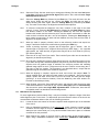
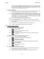
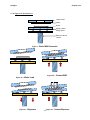
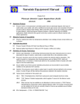
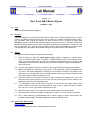
Marvell NanoLab
Member login
Lab Manual Contents
MercuryWeb
Berkeley Microlab
Chapter 4.14
0
Karl Suss MA6 Mask Aligner
(ksaligner - 382)
1.0
Titl e
Karl Suss MA6 Mask Aligner (ksaligner)
2.0
Pu rpo s e
The Karl Suss MA6 is a top and bottom side contact printer used for fine lithography down to 1 micron
or better. The MA6 is ideal for use with I-line (365 nm) resists. It is capable of processing both 4- and 6inch substrates. After reading this manual, the User should be able to describe a typical MA6
(ksaligner) process for both top and backside alignment, explain the theory of operation, and state all
hazards associated with the system. After successfully completing the qualification procedures for this
tool (see Appendix 12.1 ), the User should be able to perform a full photolithography process for both
TSA and BSA using this system. Only trained and approved (qualified) Users may use this tool.
A
3.0
H
S cop e
The system includes a number of unique features including:
4. 0
3.1
1000 W mercury arc lamp with smart power supply capable of operating in constant power
mode, or constant intensity mode. The default is constant intensity mode. In the constant intensity
mode, as the lamp deteriorates, the power is automatically adjusted to keep the intensity of the
wavelength. Also the Intensity of the lamp may be read from the power supply during exposure or
during a lamp test.
3.2
Top side wafer alignment using a conventional microscope, wafer and mask stage assemblies.
3.3
Bottom side alignment using bottom viewing optics, CCD imaging with image frame grabber and
TV monitor. This allows registration of features on the backside of a wafer to the topside of the
same wafer (e.g. through wafer etching, backside window etching for membrane formation, back
side masks for wafer-wafer bond alignment, etc.).
3.4
Automatic computer control with LCD status for User prompting and keypad entry. Up to 100
programs may be stored with five on line at any one time. Each program may be edited for key
parameters pertinent to the lithography mode.
3.5
1 of 5 lithography modes may be used for exposure. These include: soft contact, hard contact,
vacuum contact, low vacuum contact, and proximity. Each mode is easily selected by keypad
and may have certain parameters changed by the User.
3.6
Mask sizes from 5-inch to 7-inch may be used by selecting either of two mask holders.
3.7
Two different size chucks are available for patterning of either 4- or 6-inch diameter substrates.
3.8
Fast or slow scanning of mask/substrate with a memory toggle to quickly view between two
locations is also available. This makes alignment using one objective easier.
Appl i ca bl e Do cum ent s
Revision History
Karl Suss Ma6 Operating manual - hardcopy located at machine.
ksaligner
5. 0
Chapter 4.14
Def in it io ns & Pr oc e s s T e rm ino log y
5.1
WEC – Wedge Error Compensation. After loading the substrate WEC will occur. It is the
procedure by which the chuck automatically adjusts such that the substrate is perfectly parallel to
the mask (see Figures & Schematics). There are two WEC options in the four basic contact mode
programs: contact and proximity. Contact WEC relies on the overall flatness of the
mask/substrate to produce a parallel pair. Prox WEC uses a three-point contact (via prox flags)
procedure for parallel adjustment. Proximity WEC is always performed when exposing with a
proximity program, while contact programs may use either WEC option.
5.2
MA6 – The Karl Suss mask aligner. This manual describes all aspects of MA6 operation.
5.3
BA6 – The Karl Suss bond aligner. The ksaligner tool may to be converted BA6 operation;
however, there is a separate qualification procedure for BA6 (See Chapter 9.1 in the Microlab’s
Process and Equipment Operating Manual). Users must qualify on MA6 before they may qualify
on BA6.
5.4
TSA – Top Side Alignment. The top microscope is used to align mask features to the topside of
the substrate.
5.5
BSA – Back Side Alignment. The bottom side objectives are used to align mask features to the
backside of the substrate. The topside of the substrate is then exposed.
5.6
Soft Contact – One of the five possible lithography modes. The substrate is brought into contact
with the mask by a preset force during exposure.
5.7
Hard Contact - One of the five possible lithography modes. This is virtually the same as soft
contact mode save for a pillow pressure of Nitrogen that gives an additional upward force to the
wafer.
5.8
Vacuum Contact - One of the five possible lithography modes. The vacuum seal inflates to form
a chamber, which is then evacuated. The parameter PreVac time in this mode serves to allow
the vacuum to proceed slowly. This aids in preventing alignment shift.
5.9
Low Vacuum Contact - One of the five possible lithography modes. This is the same as vacuum
mode except that a small amount of Nitrogen is bled into the chamber to reduce contact force.
5.10 Proximity - One of the five possible lithography modes. The mask and wafer are separated by an
exposure distance which is User-specified in the proximity program. The mask and wafer never
actually make contact in this mode.
5.11 Prox Flags – The three pneumatically actuated components located on the bottom side of the
mask holder. They serve as spacing elements between the mask and substrate during proximity
WEC.
5.12 Overcurrent Error – This error will most likely appear during an attempt to expose. If WEC has
been improperly performed, the exposure process will draw excessive current from the motor that
brings the mask and substrate into contact. So, although this error will usually occur during an
attempt to expose, it is likely that bad WEC prior to the exposure is the cause.
6.0
Safety
6.1
Alpha particle N2 gun – This blow gun is mounted at the lower right hand side of the tool, and
should be used to neutralize and clear charged particles from the desired substrate (e.g. chuck,
wafer, mask etc.). The User should be aware that alpha particles (radioactive Polonium) are
present when this gun is used. It does not present a hazard as long as it is used properly (e.g.
solely to blow off chuck, wafer, mask, etc.). The User should never point the gun towards his or
her face.
6.2
Moving Components – The User should be aware at all times of the moving components
associated with this tool. For instance, the topside microscope assembly moves up and down,
-2-
ksaligner
Chapter 4.14
and does present a potential hazard. The User must exert caution at all times such that a limb,
finger, or article of clothing does not become trapped or entangled (or worse, violently detached)
when components of the machine are in motion.
6.3
Ultra Violet Light – The MA6 uses an Hg bulb that is filtered to a 365 nm wavelength. The lamp
2
intensity for exposure is set to 25 mW/cm by default, although the indirect light that escapes the
lamphouse during exposure is much weaker.
7. 0
St ati st ic al P roc e s s/ D at a
8. 0
Av ai l abl e P ro c es s es , P ro c es s Not e s
Process Compatible Substrate Size
KSALIGNER
8 inch
6 inch
4 inch
2 inch
die level
Vacuum contact lithography
no
yes
yes
yes ☼
yes
Contact lithography
no
yes
yes
yes ☼
yes
Proximity lithography
no
yes
yes
yes ☼
yes
☼ Requires special setup. Please contact Microlab Staff for details
8.1
8.2
The correct default idle state of the MA6 should be as follows:
8.1.1
System power ON - machine in MA6 mode.
8.1.2
Power to the TV monitor is OFF.
8.1.3
Lamp power is ON with the LED power supply readout at 900 W in constant intensity
mode. (Sometimes the display is set to intensity. It can be toggled back to power mode
by pressing the DS button.)
8.1.4
The 5-inch dummy mask and 4-inch MA6 lithography chuck are loaded. No wafer is on
the chuck.
8.1.5
Pressure = 5-6 bar; Nitrogen = 1-2 bar.
8.1.6
If lamp power is OFF (no LED readout), inform staff.
Basic Exposure Programs
8.2.1
Soft Contact – The substrate is brought into contact with the mask by a preset force
during exposure.
8.2.2
Hard Contact - This is virtually the same as soft contact mode save for a pillow pressure
of Nitrogen that gives an additional upward force to the wafer.
8.2.3
Vacuum Contact - The vacuum seal inflates to form a chamber, which is then
evacuated. The parameter PreVac time in this mode serves to allow the vacuum to
proceed slowly. This aids in preventing alignment shift.
8.2.4
Low Vacuum Contact - This is the same as vacuum mode except that a small amount of
Nitrogen is bled into the chamber to reduce contact force.
8.2.5
Proximity - The mask and wafer are separated by an exposure distance which is Userspecified in the proximity program. The mask and wafer never actually make contact in
this mode.
-3-
ksaligner
8.3
8.4
9. 0
Chapter 4.14
WEC Types
8.3.1
Contact WEC – WEC is performed by bringing the wafer and mask into direct contact.
This type of WEC should usually be used for all contact programs (as specified in the
program editor).
8.3.2
Prox WEC – Three prox flags act as spacers between the wafer and mask during WEC.
Therefore the mask and wafer never actually touch. This type of WEC has associated
with it 3 microns of error, although it is necessary for the proximity exposure program.
Compatible Resists – The following resists are compatible for use with the MA6: OCG Oi R-897
10I; OCG 825; Shipley STR-1075 thick resist and Shipley SPR 220 thick resist. For questions on
compatibility of other types of resist, please contact a ksaligner superuser.
Equ ip men t O p e r at io n
The MA6 allows 5 different program recipes (one for each contact mode) to be in online memory at one
time: a low vacuum contact program, a vacuum contact program, a hard contact program, a soft contact
program, and a proximity program. One of these 5 programs may be immediately chosen by simply
pushing the Select Program key until the appropriate program appears in the display. 100 programs
(numbered 0-99) may be stored in archived memory. These programs must be loaded before they can
be executed. Only one program per contact mode may be loaded into online memory at a time.
9.1
Viewing, loading, saving, and editing a program
9.1.1
Viewing a program
9.1.1.1 Press the Edit Program key. The keypad will flash.
9.1.1.2 Press the Y (up/down arrow) keys. Each program #, contact mode, alignment
gap and exposure time will be displayed as you scroll through each program.
You can scroll up or down through the list by pressing the Y-up or Y-down key.
9.1.1.3 To exit viewing a program, press the flashing Edit Program key.
9.1.2
Loading an already stored program
9.1.2.1 Press the Edit Program key. The keypad will flash.
9.1.2.2 Press the X-lateral key to scroll among: 1; save prim to, 2; load prgm from, 3;
delete prgm #, and 4; exit prgm editor without change. Scroll to 2; load prgm
from.
9.1.2.3 Press the Y –up/down key until the desired program number appears in the
LCD display
9.1.2.4 Press the flashing Edit Program key to load the stored program into online
memory.
9.1.2.5 EXAMPLE: Loading program 9:
9.1.2.6 Press the Edit Program key. The keypad will flash.
9.1.2.7 Press the X-lateral key once to scroll to load prgm from.
9.1.2.8 Press the Y-up/down key 9 times to scroll to recipe 9.
9.1.2.9 Press the Edit Program key again to both load the recipe and exit the editor.
9.1.3
Changing parameters in a program
9.1.3.1 Load the desired program as described previously.
9.1.3.2 Press the Edit Parameter key. The keypad will flash.
-4-
ksaligner
Chapter 4.14
9.1.3.3 Press the X-lateral key to scroll through the parameters. For soft or hard contact
modes the parameters are: Expose Time, Alignment Gap, and Wedge Error
Compensation (WEC) type. NOTE: For vacuum mode there are additional
parameters. Select the parameter(s) to be changed.
9.1.3.4 Press the Y-up/down key to change a parameter to the desired value.
9.1.3.5 Press the Edit Parameter key again. The change should appear on the display
(pad stops flashing). Note that this program must still be saved for future use.
9.1.4
Saving the current program to a different memory slot
9.1.4.1 Press the Edit Program key. The pad will flash, and save prgm to should be
displayed.
9.1.4.2 Press the Y-up/down key to select the program # to save to. When you save a
program the position of the objectives is also saved. NOTE: DO NOT save
programs to memory slot #’s 1-10.
9.1.4.3 Press the Edit Program key again to execute the save.
9.1.5
Deleting a program
9.1.5.1 Press the Edit Program key. The pad should flash.
9.1.5.2 Press the X-lateral key twice to scroll to option 3; delete prgm #.
9.1.5.3 Press the Y-up/down key until the program you wish to delete appears.
9.1.5.4 Press the flashing Edit Program key again. The flashing should stop, and the
program should now be deleted.
9.1.6
Exiting Edit Program mode without making a change
9.1.6.1 Press the Edit Program key. The pad will flash.
9.1.6.2 Press the X-lateral key until option 4, exit prgm editor is displayed.
9.1.6.3 Press the Edit Program key again to exit.
9.1.7
Changing a parameter without loading a new program
9.1.7.1 EXAMPLE 1: Changing the exposure time for the next substrate only.
9.1.7.1.1 Press the Edit Parameter key. Exp time should be displayed.
9.1.7.1.2 Press the Y-up/down key to increase/decrease the exposure time.
9.1.7.1.3 Press the flashing Edit Parameter key once more. The new exposure
time should now be displayed.
9.1.7.2 EXAMPLE 2: Changing the alignment gap for the next substrate only:
9.1.7.2.1 Press the Edit Parameter key.
9.1.7.2.2 Press the X-lateral key until Al Gap is displayed.
9.1.7.2.3 Press the Y-up/down key to set the desired value of Al Gap.
9.1.7.2.4 Press the flashing Edit Parameter key again to save this new value.
NOTE: The separation key pads (^) also serve to adjust the parameter
Al Gap without having to enter the program editor.
-5-
ksaligner
9.2
Chapter 4.14
Mask Loading
There are two different size mask holders (trays); one for 5-inch masks, and one for 7-inch
masks.
9.3
9.2.1
Press the Change Mask key. This key and the Enter key will flash.
9.2.2
Verify on the LCD display that the vacuum holding the mask is ON before pulling out the
tray. If the vacuum is OFF, press the Enter key to toggle the vacuum ON. Pull the mask
tray out, gently flip it over, and place it on the special shelf at the left of the machine.
9.2.3
Release the spring-loaded clip to the mask and toggle the vacuum OFF by pressing the
Enter key. The mask may then be carefully removed.
9.2.4
If a different size mask tray is desired, disconnect the vacuum hose at the machine (not
tray). Push in on the red knurled knob and gently pull on the hose. Place the unwanted
tray in the Karl Suss storage cabinet. Place the new tray upside down on the special shelf
to the left of the machine. The vacuum hose should be facing toward the User and to the
right. Reconnect the vacuum hose. Note that the 5-inch mask tray is the default for this
system. Users who change to a 7-inch tray should change it back to the 5-inch once they
are done.
9.2.5
Place the mask to be used onto the tray, emulsion/chrome side up. Use the three
alignment pins to center the mask over the tray aperture.
9.2.6
Press the flashing Enter key to turn the vacuum ON. Verify that the vacuum is ON by
reading the vacuum gauge. It should read less than –0.7.
9.2.7
Push the silver tab down on the spring loaded clip to engage it against the mask.
CAUTION: This clip may not be strong enough to hold the mask in place when the tray is
inverted. The vacuum should always be ON before the tray is inverted or the mask will
drop and possibly break.
9.2.8
Turn the tray over such that the mask is on the bottom facing up. Carefully slide the tray
back into the mask frame’s dovetail grooves.
9.2.9
Press the Change Mask key again. The flashing light will extinguish, and the mask tray
will be locked into place. A Ready for Load message should then appear on the LCD
display.
Substrate Loading
There are two wafer chucks; one for 4-inch and the other for 6-inch size substrates. The vacuum
grooves on the chuck must be completely covered by your substrate. These chucks are meant to
be used with the correct size mask tray only. In other words, the 4-inch chuck must be used in
conjunction with the 5-inch mask tray, and the 6-inch chuck with the 7-inch mask tray.
CAUTION: These chucks are made by precision machining and should be handled with extreme
care. Do not drop, scratch or otherwise damage them. Store an unused chuck at its proper
location in the Karl Suss storage cabinet (shelf on the wall).
9.3.1
Adjust the stage rotation knob to 0 (zero) (such that the rotation indicator is centered) and
set the X and Y stage micrometers to 10 (ten).
9.3.2
Press the Load key and pull the substrate slide straight out. The Enter and Unload lights
should flash.
9.3.3
Verify that the chuck and red vacuum seal are clean from stains or particles. Use the
alpha-particle Nitrogen gun to remove particles from the chuck. Use IPA (Isopropyl
Alcohol) and a clean wipe to remove any stains. DO NOT allows IPA to get on the seal.
DO NOT use acetone to clean the chuck. If the chuck is dirty enough to require an
acetone clean, inform staff. Furthermore, leaving resist or particles on the chuck can be
grounds for disqualification. Ensure that the chuck and tool in general is left in a clean
state when finished.
-6-
ksaligner
9.4
9.5
Chapter 4.14
9.3.4
If a different size chuck is desired, gently lift the chuck from the bottom side of the slide
and place it in the KS storage cabinet. Then place the desired chuck into the circular
opening within the slide (seal faces up). Ensure that the white tick mark on the chuck is
aligned to the steel pin on the slide. Always handle the chuck by its metal rim. DO NOT
touches the center of the chuck.
9.3.5
Place the substrate on the center of the chuck with the major flat facing the User. Ensure
that all the vacuum grooves are covered. When placed properly, the substrate should
touch up against the three small steel alignment pins on the chuck.
9.3.6
Press the Enter key to toggle the substrate vacuum ON.
9.3.7
Slowly push the slide all the way back into the machine.
9.3.8
Push the Enter key again. WEC will then be performed. After WEC, the substrate is
ready to be aligned to the mask.
TSA Setup
9.4.1
Position both objectives over the mask using the X-Y arrow keys. A swifter movement of
the objectives may be obtained by toggling the Fast key. The key will illuminate when in
fast mode.
9.4.2
The distance between the left and right objectives may be adjusted by means of the
lateral separation knobs. Each separation knob is located on the left and right side of the
objectives. In general, it is best to find an alignment mark at the extreme left and right
side of the mask. The rotation knob located at the front of the microscope allows the
theta, or rotational angle of both objectives to be adjusted.
9.4.3
Rotate the field select knob to the center position to obtain a split-field view on the
monitor. A split-field view denotes when the left and right objective images may be seen
simultaneously. It is also possible to view a full-screen image of the left or right objective
by adjusting the field select knob accordingly.
9.4.4
The intensity of illumination from the objectives may be adjusted by means of the
illumination control knobs. First ensure that TSA is selected, and then adjust to the
desired intensity using the illumination knob for TSA.
9.4.5
The large coarse focus knob is located at the top of the TSA microscope. Naturally, this is
used for bringing the objective’s depth of focus into the fine focus range. Fine focusing
may be adjusted by means of the focus control knobs. The fine focus knobs labeled Top
Substrate should be used to focus on the mask. The fine focus knobs labeled Bottom
Substrate should be used to focus on the wafer. The Top/Bottom key may be toggled to
switch focus control between the two sets of fine focus knobs. When illuminated, the
Top/Bottom key will provide focus control to the Top Substrate knobs. When the
Top/Bottom key is not lit, focus control is allotted to the Bottom Substrate knobs. Note:
This logic applies to both TSA and BSA processes.
9.4.6
MA6 has the ability to remember microscope position via the Set Reference key. To use
this option, position the microscope to the first reference location using the X-Y arrow
keys. Then press the Set Reference key (key becomes illuminated). Next, reposition the
nd
microscope to the 2 desired location using the X-Y arrow keys. Finally, press the Scan
key. The microscope will automatically move back to the first reference location. Pressing
nd
the Scan key once more will move the microscope to the 2 location. Note: This feature
is also available for use with the bottom side microscope.
Wafer Alignment
CAUTION: Before any attempt to align, ensure that the machine is in alignment mode. The
Alignment/Cont key will be illuminated when the machine is in alignment mode. If the system is
in contact mode (orange contact LED illuminated), any attempt to align will scratch/ruin the mask
and wafer, and possibly damage the machine.
-7-
ksaligner
9.5.1
Locate the three micro-manipulators near the bottom left and right sides of the stage.
These allow the chuck (upon which the wafer rests) to be moved (X, Y, and R-rotation)
relative to the mask.
9.5.2
If resistance is felt during wafer movement, press the separation key labeled v to
increase the distance between the wafer and mask (z value becomes more negative).
The other separation key labeled ^ will decrease the distance between the wafer and
mask (z value on LCD display becomes less negative).
9.5.3
Alignment shift between the mask and substrate may sometimes occur during the contact
exposure process. To ensure proper alignment before exposure, press the Alignment
Check key. When this is done, the machine will undergo all the steps in the contact
program up to the actual exposure (i.e. vacuum pump down, N2 boost, etc.). Any shift
may then be observed through microscope. If unacceptable shift is observed, the
substrate or mask may need to be re-cleaned, WEC may need to be redone, or a
pressure adjustment may need to be made (inform staff). DO NOT attempt to re-align the
substrate in contact Mode. Ensure the wafer and mask is separated before re-aligning
the wafer (toggle with Alignment Check key). If the alignment is acceptable, the wafer
may be subsequently exposed. Note: The Alignment Check key is not available for
proximity or soft contact modes. Use the Alignment/Cont key instead.
Wafer Exposure
The lamp power supply is by default set to CI (constant Intensity at 365 nm) mode with a 900 W
2
LED readout prior to exposure. The standard system lamp output intensity is 20 mW/cm . If
different intensities are required, discuss with staff beforehand.
NOTE: A steady beep during exposure indicates that the power supply has reached its maximum
2
output power and the target output intensity is less than 20 mW/cm . The beep does not indicate
the lamp needs to be changed. A problem report filed in Mercury is not required.
KSALIGNER LAMP ACTUAL INTENSITY (i-line) vs POWER
1250
25
20
1150
BEEP
15
1100
1050
10
1000
New lamp
install
Max power
5
● observedintensity
power
950
● observedpower
intensity
900
Power, Watts
1200
Intensity, mw/cm^2
9.6
Chapter 4.14
850
0
06/28/05 07/01/05 07/15/05 07/25/05 08/03/05 08/18/05
TIME
The graph above demonstrates this situation; as the lamp becomes older more power is needed
to achieve the same output intensity. Eventually the power supply will max out at 1200 V and the
2
output intensity of the lamp will not achieve 20 mW/cm . In the case of an audible alarm you
must check the Mercury login header file and use the reported intensity (previously measured by
staff) to calculate the necessary exposure time. Use the equation Dose = Intensity x Time. For
2
example, if you require an exposure dose of 154 mJ/cm and the reported intensity on Mercury is
2
2
14 mW/cm , you will need to use an exposure time of 11 seconds (e.g. 155 mJ/cm
=
-8-
ksaligner
Chapter 4.14
2
14 mW/cm x 11 sec.). Refer to Chapter 4.1 for the recommended exposure dose of common
photoresists used in the Nanolab.
9.7
9.6.1
If the exposure time must be changed, press the Edit Parameter key (do this prior to
loading the wafer). Use the Y-arrow keys to change the exposure time. Then press the
Edit Parameter key again. The LCD readout in the program should reflect the changed
exposure time.
9.6.2
Press the Exposure key. The top side microscope assembly will lift, and the exposure
assembly will slide out over the mask.
9.6.3
After exposure, the microscope will drop back down over the mask. The exposed wafer is
then ready to be unloaded.
9.6.4
Pull the wafer tray out and press the Enter key to toggle the vacuum OFF. Remove the
exposed substrate, and slide the wafer tray back into the machine.
9.6.5
NOTE: The ksaligner has a multiple exposure mode allowing the user to expose resists
multiple times without changing the alignment. For example, one can align the sample to
the mask, expose for XX seconds, and rest for YY seconds and repeat this ZZ times.
This is particularly useful for thick resists (e.g. SU-8 and SPR220) where the exposure
time can be long and heating of the resist can be an issue. Therefore, one would like to
break the exposure up into smaller time intervals allowing the sample to cool in between
the smaller exposures. To use this feature, press the Multiple Exposure button on the
main console. When illuminated this allows the user to edit additional parameters in the
Edit Parameter menu. The user can now specify the exposure time of the interval, the
rest time between intervals, and the number of cycles of exposure to be completed (Note
the total exposure time, when in this mode, is equal to the exposure time listed in the Edit
Parameter menu times the number of cycles listed in the Edit Parameter menu).
Bottom Microscope Setup
The bottom microscope is used to print a pattern on the backside of a substrate that is aligned to
a pattern on the front side of the substrate. It accomplishes this by using a stored image of the
mask prior to loading the substrate. The mask and microscope then lock into place while the
substrate is loaded patterned side down, resist side up. The patterned wafer may then be viewed
by the bottom microscope, and alignment may be accomplished by moving the wafer. Both the
mask's stored image and the real time wafer image are viewed on the TV monitor during this
procedure. NOTE: The top microscope may NOT be used during the following procedure.
9.7.1
Verify that MA6 is in the default idle mode.
9.7.2
Select the desired program and parameter settings as described previously.
9.7.3
Load the desired mask as previously described.
9.7.4
Select BSA/IR on the front panel’s illumination switch.
9.7.5
Activate the bottom microscope movement controls by pressing the BSA Microscope
key (key should illuminate). The X-Y and Fast keys may now be used to move the bottom
microscope objectives.
9.7.6
Three keypads, Left, Both, and Right determine the bottom objectives’ mode of
movement. When the Left key is selected (key illuminated), the left objective movement
only is controlled by the X-Y keys. The Right key controls the right objective movement
only. The Both key controls movement of both objectives at the same time.
9.7.7
Press the Top/Bottom key to activate mask focus (key should be illuminated).
-9-
ksaligner
Chapter 4.14
9.7.8
Adjust the Top Substrate (mask) left and right focus knobs to obtain a sharp image on
the monitor.
9.7.9
The bottom microscope position may be read from the LCD. XL = left objective x position;
XR = right objective x position, YL = left objective Y position etc... The following
coordinates place the BSA objectives directly under the windows on the chuck: XL
23mm; YL 48 mm; XR 23 mm; YR 48 mm. Effective rotation may be accomplished by
moving one objective relative to the other. The Set Reference key may be used as
described previously.
9.7.10 Find the alignment marks on the mask (use split field mode). Adjust the left and right
illumination knobs if necessary to obtain a clear image on the monitor.
9.7.11 After ensuring that the alignment marks are in focus, press the Grab Image key to
capture a mask image. NOTE: This must be done each time a new substrate is loaded...
The bottom microscope objectives will consequently lock and may not be moved. To
cancel the stored image, press the Grab Image key again.
9.7.12 Press the Load key. Pull the wafer tray out and load the substrate patterned-side down
(resist side up). Press the Enter key to toggle the vacuum to the wafer on.
9.7.13 Slide the tray back into machine and press the Enter key. WEC will be performed and a
fuzzy image may appear on the monitor.
9.7.14 Ensure the Top/Bottom key is toggled to the bottom mode (key NOT illuminated).
9.7.15 Adjust the Bottom Substrate focus and illumination knobs to obtain a clear image of the
wafer.
9.7.16 Alignment of the wafer to the mask may now be done by moving the chucks X, Y, and R
knobs. Once the alignment is complete, The wafer may be exposed.
9.8
Backside Alignment for Small Dies
MA6 provides a mechanism for performing backside alignment using only one objective (rather
than both, which are used for wafer alignment). This is necessary since the objectives cannot be
brought close enough together to do a conventional alignment.
9.8.1
Make a die holder by using a 4" Pyrex wafer, and three pieces of a Silicon wafer. The die
may simply be placed in the center of the Pyrex wafer. If desired, the User may
additionally mount the die using wax, photoresist (Note: Photoresist PR1818 works well
for small die. 4000 rpm, 30 s gives ~2.0 um thickness; use chlorobenzene (12 minutes)
for PR undercut; exposure of 4.5s; edge beads do not need to be removed if working with
large features (50 um no problem)), or a drop of water. Pieces of Silicon must be glued
(crazy glue) to the Pyrex in the locations where the WEC flags land. This is necessary for
WEC to occur properly. Prepare a mask with features located over the windows (holes) of
the 4" wafer chuck.
9.8.2
Carefully remove the 4" lithography chuck, and locate the three flathead screws on the
bottom side that correspond with the alignment pins. Use a screwdriver to turn each
screw counter clockwise (¾ turn for each should do it). This should lower the alignment
pins such that a vacuum may be held against the 5” mask. Ensure that the alignment pins
are successfully retracted, and then replace the chuck.
9.8.3
IMPORTANT: This step is different from normal mask loading, as the mask itself will later
be rotated during alignment. Select the Change Mask key, and slide the mask tray out of
the mask frame. Flip the tray over and place it on the special shelf to the left of the
machine. Release the spring clip, and toggle the vacuum OFF with the Enter key.
Remove the dummy mask. Place the actual mask on the tray such that it is as far away
from the pins as possible. Leave the spring clip in the OPEN position. Toggle the vacuum
ON with the Enter key and ensure that the mask is being held by a vacuum. Replace the
mask tray back in the machine.
- 10 -
ksaligner
Chapter 4.14
9.8.4
Select the F1 key. Use the arrow keys to change the following: Set the mask load option
to by slide, followed by the back side aligns (BSA) option. Also, select the turn single
BSA adjustment ON setting.
9.8.5
Select the Change Mask key followed by the Enter key. The mask will lower onto the
wafer chuck. Gently pull the tray out, confirm with Enter, and slide the tray back in
without touching the mask. Again, select the Change Mask key, followed by the Enter
key. The mask is now ready to be aligned to the bottom side objective.
9.8.6
To orient the mask with the objectives’ axis, find a location on the edge of the mask
(using X, Y keys). Press the Set Reference key followed by the Grab Image key. Next,
find another location on the mask. Pressing the Scan key will move the objective
between this location and the reference point. Use the rotation micrometer to rotate the
mask so that it coincides with the x axis of the objective. Pressing the Grab Image key
twice reloads a new image. Go back and forth between the two points until the mask is
aligned to the objective’s axis.
9.8.7
When the mask is properly oriented, return to the reference position and acquire an
image. Transfer the mask to the mask holder by pressing the Enter key.
9.8.8
Select a proximity exposure program with an alignment gap of ~200um, and an
exposure gap of: [height of die - height of Silicon piece (for WEC flags) + the intended
gap between the mask and die]. A typical value may be 90 um for a GaAs die (375 um)
(thin Silicon (290 um)).
9.8.9
Place the die on top of the Pyrex wafer. Then load the Pyrex wafer into the machine for
alignment (as described previously).
9.8.10 Once the die is loaded, the proximity flags should come out over the Silicon pieces on the
Pyrex wafer during WEC. Backside alignment may then be performed. Because only one
objective and one grabbed image is available, the reference position and matching
grabbed image option for the X-Y alignment must be used. Perform a scan along the XAxis only to align the rotation. The procedure is as described above, except that the
grabbed image is not released; the die will be aligned to it.
9.8.11 When the aligning is complete, expose as usual, and remove the sample. Note: To
expose multiple chips, the reference image needs to be regrabbed. After removing the
sample, replace the wafer chuck slide. Focus on the mask, and then grab the image
(ensuring it is at the reference location). Press the Load key, and insert another die.
Proceed as described previously.
9.8.12 When finished, remove the Pyrex wafer die holder, and raise the wafer chuck pins using
a flat head screwdriver. Press the F1 key. Set the mask load option to load manually.
Also choose the option: turn single BSA adjustment OFF. Furthermore, leave the tool
in its default mode, as described in the following section.
9.9
MA6 Chuck Pin Adjustment
For some applications (wafers without flats), it may be necessary to adjust the height of the three
wafer-alignment pins on the chuck. To adjust these pins such that the surface of the chuck can
accommodate a substrate without a flat, use the following procedure:
9.9.1
Locate the three set screws for the each respective wafer-alignment pin on the backside
of the chuck.
9.9.2
Using a flatheaded screwdriver of the correct size, gently rotate the screws counterclockwise until the height of the pins are lower than the surface of the chuck. DO NOT
attempt to use a razor blade, pen, or any other makeshift instrument in place of a flathead
screwdriver for this procedure.
9.9.3
When finished, the height of the pins must be adjusted back to their default position.
Again, using a flatheaded screwdriver of the correct size, CAREFULLY AND GENTLY
- 11 -
ksaligner
Chapter 4.14
rotate the screws clockwise until the thread can be turned no more, and the height of the
pins is at a maximum. DO NOT torques the screws tight in this step! Doing so will ruin the
chuck! Finally, gently rotate each screw back one-half turn counter-clockwise. This will
set the pins at their default height for general use.
9.10 Machine Shutdown
9.10.1 When finished exposing, remove the final substrate. Ensure that the wafer chuck is clean
(free of particles and resist) and slide the wafer tray all the way into the machine.
9.10.2 Press the Change Mask key. With the mask vacuum ON, pull the mask tray out and
place it inverted on the mask load shelf. Press Enter to toggle the vacuum OFF. Release
the spring clip, remove the mask, and re-load the dummy mask. Toggle the vacuum ON
with the Enter key, and engage the spring clip. Slide the mask tray back into the
machine. (The tray should be flush with the guides.)
9.10.3 Press F1 followed by Enter to lower the top microscope head.
9.10.4 Ensure the BSA/IR TSA knob is set to TSA. Ensure the bottom microscope is OFF.
9.10.5 Ensure the illumination knobs for both BSA and TSA are turned all the way counter
clockwise (OFF).
9.10.6 Leave the power to the machine ON. It should also be left in MA6 mode.
9.10.7 Turn the TV-monitor OFF and disable the machine on the wand.
10 . 0 Trou bl e shoot ing G u i del in e s
10.1 Problem: Mask features cannot be focused.
10.1.1 Cause: The mask is upside down.
Solution: Reload the mask.
10.1.2 Cause: The mask tray is not properly locked down.
Solution: Reload the mask tray.
10.1.3 Cause: The mask is not resting flat against the mask tray (e.g. particle on mask).
Solution: Clean mask.
10.2 Problem: The mask is focused clearly, but the wafer is not.
10.1.4 Cause: The alignment gap may be too large.
Solution: Adjust the alignment gap using the separator keys.
10.2.2 Cause: WEC was done incorrectly.
Solution: Unload and reload the wafer.
10.2.3 Cause: The wafer or mask is contaminated thus preventing the wafer from being
properly located in Z direction.
Solution: Clean mask/wafer.
10.2.4
Cause: N2 pressure setup is incorrect.
Solution: Inform staff.
10.3 Problem: Overcurrent Error During Exposure
10.3.1 KSaligner may be reset at this point by turning the green ON/OFF switch to OFF. Wait
ten seconds and turn switch back to ON position.
10.3.2 KSaligner will boot, and prompt user for MA6 vs. BA6 configuration. Select MA6.
- 12 -
ksaligner
Chapter 4.14
10.3.3
If overcurrent error reoccurs later in process, report a fault on the WAND and abort
processing at KSaligner. It is important to describe in detail *exactly* when the
overcurrent error appeared.
Cause:
Particles on wafer or mask.
Solution: Clean mask/wafer. If problem continues, report on faults with a detailed
description (e.g. like exactly at what step the overcurrent error occurred in the
User’s process).
Cause: Can occur due to bad prox WEC – prox flag not extending properly.
Solution: Report on faults.
- 13 -
ksaligner
Chapter 4.14
11 . 0 Figu r es & Sc he ma t i c s
Mask Holder
Mask
Wafer
Spring Loaded
Wedge Head
Motorized Screw
Thread
Figure 1 -
Figure 2a
– Wafer Load
Figure 2c -
Alignment
Basic MA6 Schematic
Figure 2b
Figure 2d - 14 -
– Contact WEC
Contact Exposure
ksaligner
Chapter 4.14
Large Particle
Figure 3a
– Wafer Load
Figure 3c
Figure 3b -
Bad Contact WEC
- Exposure Attempt –
OVERCURRENT ERROR!
- Alignment
Figure 3d
12.0 App end ic e s
12.1 Qualification Procedures
12.1.1 After studying the MA6 User Manual, potential new users should arrange ahead of time
to have an existing user review the MA6 operation. Casual questioning (e.g. Hey, can
you review this with me for a moment?) is not to be considered an official review
period.
12.1.2 The first question that should be asked is whether Chapter 4.14 - Karl Suss MA6 Mask
Aligner on the web and the equipment header file has been thoroughly reviewed? If not,
the current User should insist that it be reviewed before the meeting.
12.1.3 The meeting between the current and new user should be scheduled for enough time to
explain equipment operation; Loading and unloading the mask and substrate, TSA uses
the top microscope, BSA using the bottom microscope, the exposure process, and a
review of system errors. (I cannot see this taking less than 60 minutes as subtleties of the
MA6 process are sure to come up for discussion). Equipment time and dummy wafer
should be recharged to new user’s account.
- 15 -
ksaligner
Chapter 4.14
12.1.4 Step #3 should be done at least twice by two different current users.
12.1.5 Upon successful completion of Step 12.4, new users should take the MA6 Users Test.
Tests are administered by Microlab office staff (Leon), and are graded by BSAC
Engineering staff (Matt Wasilik). Estimate 2-5 days for grading. The idea of the test is to
simply make sure all new users understand the material. Satisfactory completion of this
test will enable the user to meet with a Superuser for qualification.
12.1.6 Superusers will first ask, who trained you? of the new user. Training implies adequately
following Step 12.1-12.4 above. The Users identified as being the ones who did the
training will be responsible for the information conveyed by the new user during the
qualification. It is suggested that the test be reviewed with another user while at the
ksaligner tool before taking the final oral qualification with the superuser.
12.2 Description of Alignment Target Placement
What follows is a description of how to place alignment targets to correspond with the
backside/backside (FS/BS) holes in the lithography chuck.
12.2.1 The bottom side objectives can travel from 24 to 95 mm apart. The chuck has two
rectangular holes through which the backside objectives view the wafer. On the 4"
chuck, these holes are 3 cm x 2 cm, with the longer side along the x-axis, and symmetric
around the x-axis. They have rounded corners, so it's best to keep the alignment marks
well within these areas.
12.2.2 The rectangular holes have diagonals of endpoints (-4.5, 1), (-1.5, -1) and (4.5, 1), (1.5, 1) -- with 0, 0 at center of chuck, and in units of cm.
12.2.3 For the 6" chuck, the diagonals are (-6.5, 1), (-2, -1) and (6.5, 1), (2, -1) -- again with 0, 0
at center of chuck, and in units of cm. In the 6" case the holes are 4.5 cm x 2 cm.
- 16 -
ksaligner
Chapter 4.14
KSAligner/MA6 Study Guide
Be sure to know...
1.
2.
3.
4.
5.
6.
7.
8.
9.
10.
11.
12.
13.
14.
15.
16.
17.
18.
19.
20.
21.
22.
23.
24.
25.
26.
27.
28.
29.
30.
31.
32.
Idle lamp power, pressure and nitrogen readings.
Types of aligning available for different size substrates.
If power supply module's LED is off...
How to load, save and change parameters within programs.
How to secure a mask in the frame.
How to hold the wafer chuck.
Placing the substrate on the chuck for TSA.
How to obtain a straight profile.
Top and bottom substrate knobs.
Troubleshooting mask and wafer focusing difficulties.
Using the Set Reference Key.
How to obtain a split field view.
Why to NOT move micromanipulators in contact mode.
Feeling resistance with chuck in alignment mode.
If the alignment shift is unacceptable.
Normal average intensity of the lamp.
Beep during exposure.
What happens when you press exposure key, grab image key.
Why to use silicon pieces with 1 x 1 cm die.
Returning the system to default mode.
Why use the bottom microscope set-up, what it aligns to.
Possible modes during lithography.
Alignement gap vs. Exposure gap.
The meaning and purpose of WEC, troubleshooting WEC.
Why hard bake photoresist on wafer.
Overcurrent error meaning and troubleshooting.
Adjusting exposure for different intensities.
Removing, changing and replacing a mask.
Acetone and ksaligner.
Removing particles from the chuck and mask holder.
Emergency OFF button.
Difference between MA6 and BA6 modes.
- 17 -