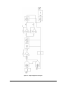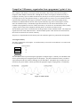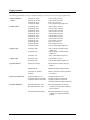
1
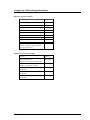
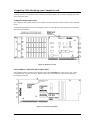
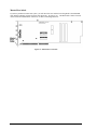
GAGE APPLIED TECHNOLOGIES
CompuGen ISA Hardware Manual
and Driver Installation Guide
Reorder #: MKT-HWM-ISA01
0506
© Copyright Gage Applied Technologies 1999, 2000, 2004, 2005
First Edition (June 2005)
GAGE, COMPUSCOPE, and COMPUGEN are registered trademarks of Gage Applied Technologies, Inc. MS-DOS, WINDOWS 95, WINDOWS
98, WINDOWS ME, WINDOWS NT, WINDOWS 2000 and WINDOWS XP are trademarks of Microsoft Incorporated. LabVIEW is a registered
trademark of National Instruments. MATLAB is a registered trademark of The MathWorks Inc. IBM, IBM PC, IBM PC/XT, IBM PC AT
and PC-DOS are trademarks of International Business Machines Corporation. All other trademarks are registered trademarks of their
respective companies.
Changes are periodically made to the information herein; these changes will be incorporated into new editions of the publication. Gage
Applied Technologies, Inc. may make improvements and/or changes in the products and/or programs described in this publication at any
time. The latest copy of this manual can be found on our web page at www.gage-applied.com in the Support section, Software & Manuals.
Copyright © 1999, 2000, 2004, 2005 Gage Applied Technologies, Inc. All Rights Reserved, including those to reproduce this publication or
parts thereof in any form without permission in writing from Gage Applied Technologies, Inc. The installation program used to install the
GageScope Software, InstallShield, is licensed software provided by InstallShield Software Corp., 900 National Parkway, Ste. 125,
Schaumburg, IL. InstallShield is Copyright ©1998 by InstallShield Software Corp., which reserves all copyright protection worldwide.
InstallShield is provided to you for the exclusive purpose of installing Gage Software. In no event will InstallShield Software Corp. be able
to provide any technical support for Gage software.
Please complete the following section and keep it handy when calling Gage for technical support:
Owned by:
Serial Number(s):
Purchase Date:
Purchased From:
___________________________
___________________________
___________________________
___________________________
___________________________
You must also have the following information when you call:
·
·
·
·
·
·
Software Driver & Application Version
Software Development Kit, if applicable
Brand name and type of computer
Processor and bus speed
Total memory size
Information on all other hardware in the computer
How to reach Gage Applied Technologies for Product Support
Toll-free phone: (800) 567-GAGE
Toll-free fax: (800) 780-8411
To reach Gage from outside North America
Tel: +1-514-633-7447
Fax: +1-514-633-0770
Email: [email protected]
Website: www.gage-applied.com
Table of Contents
Preface....................................................................................................................................................................ii
Preventing ESD ......................................................................................................................................................1
General safety summary .........................................................................................................................................2
Driver installation guide ......................................................................................................................................3
Installing drivers and applications ..........................................................................................................................4
CompuGen ISA Drivers ...................................................................................................................................12
CompuGen Software Development Kits (SDKs) .............................................................................................15
CompuGen Application (CGWIN)...................................................................................................................19
GageBit Application.........................................................................................................................................20
What you should receive with your CompuGen 1100 .....................................................................................21
Fundamental concepts ..........................................................................................................................................23
CompuGen 1100 product introduction .................................................................................................................24
CompuGen 1100 specifications............................................................................................................................25
CompuGen 1100 ordering information ................................................................................................................27
CompuGen 1100 block diagram...........................................................................................................................28
CompuGen 1100: identifying your CompuGen card............................................................................................29
CompuGen 1100: identifying optional features....................................................................................................31
Master/Slave option..........................................................................................................................................31
External Clock option.......................................................................................................................................31
CompuGen 1100 connectors and headers.............................................................................................................32
CompuGen 1100: I/O address ..............................................................................................................................34
DIP switch SW2 and ISA bus address lines .....................................................................................................35
Generally available I/O addresses and corresponding SW2 settings ................................................................36
CompuGen 1100: installing a single card.............................................................................................................37
CompuGen 1100: installing multiple cards ..........................................................................................................39
CompuGen 1100: verifying proper setup using the CompuGen Application.......................................................42
Starting CGWIN...............................................................................................................................................42
Using CGWIN to test your card .......................................................................................................................43
Using the configuration utility..........................................................................................................................43
CompuGen 1100 triggering ..................................................................................................................................45
CompuGen 1100 output amplifiers ......................................................................................................................46
CompuGen 1100 memory organization................................................................................................................48
CompuGen 1100 memory organization from a programmer’s point of view ......................................................49
What you should receive with your CompuGen 3250 .....................................................................................51
CompuGen 3250 product introduction .................................................................................................................53
CompuGen 3250 specifications............................................................................................................................54
CompuGen 3250 ordering information ................................................................................................................56
CompuGen 3250 block diagram...........................................................................................................................57
CompuGen 3250: identifying your card ...............................................................................................................58
CompuGen 3250 optional features .......................................................................................................................60
Master/Slave option..........................................................................................................................................60
External Clock option.......................................................................................................................................60
CompuGen 3250 connectors and headers.............................................................................................................61
CompuGen 3250 I/O address ...............................................................................................................................63
CompuGen 3250: installing a single card.............................................................................................................66
CompuGen 3250: installing multiple cards ..........................................................................................................67
CompuGen 3250 troubleshooting with GageConfig ............................................................................................69
CompuGen 3250: generating a pattern using GageBit .........................................................................................71
CompuGen 3250 triggering ..................................................................................................................................72
CompuGen 3250 output drivers and connector ....................................................................................................73
CompuGen 3250 accessories................................................................................................................................74
CompuGen 3250 memory organization................................................................................................................75
Technical Support ..............................................................................................................................................77
Gage products .....................................................................................................................................................78
Gage CompuGen ISA Hardware Manual and Driver Installation Guide
i
Preface
This manual provides detailed information on the hardware features of CompuGen Analog Output cards. This
information includes specifications, block diagrams, connector descriptions, memory architecture descriptions,
etc.
In addition, this guide takes you through the process of installing your CompuGen card(s) and describes
available custom features.
It is assumed that the reader is familiar with using PCs, Windows and ISA bus cards. No description is included
for these topics. If you are not comfortable with these areas, it is strongly recommended that you refer to the
relevant product guides.
To maintain the accuracy of the information contained herein, we reserve the right to make changes to this
manual from time to time.
Note: For brevity, in this manual,
“CompuGen 1100” is abbreviated as “CG1100”
“CompuGen 3250” is abbreviated as “CG3250”
ii
Gage CompuGen ISA Hardware Manual and Driver Installation Guide
Preventing ESD
Before installing or servicing this product, read the ESD information below:
CAUTION. Static discharge can damage any
semiconductor component in this instrument.
!
When handling this instrument in any way that requires access to the on-board circuitry, adhere to the following
precautions to avoid damaging the circuit components due to electrostatic discharge (ESD).
1.
Minimize handling of static-sensitive circuit boards and components.
2.
Transport and store static sensitive modules in their static protected containers or on a metal rail. Label
any package that contains static sensitive boards.
3.
Discharge the static voltage from your body by wearing a grounded antistatic wrist strap while handling
these modules and circuit boards. Do installation and service of static-sensitive modules only at a
static-free work station.
4.
Nothing capable of generating or holding a static charge should be allowed on the work station surface.
5.
Handle circuit boards by the edges when possible.
6.
Do not slide the circuit boards over any surface.
7.
Avoid handling circuit boards in areas that have a floor or work-surface covering capable of generating
a static charge.
Preventing ESD
1
General safety summary
Review the following safety precautions to avoid injury and prevent damage to this product or any products
connected to it. To avoid potential hazards, use this product only as specified.
Observe all terminal ratings.
To avoid fire or shock hazard, observe all ratings and markings on the product. Consult the product manual for
further ratings information before making connections to the product.
Do not apply a potential to any terminal, including the common terminal, that exceeds the maximum rating of
that terminal.
Do not operate with suspected failures.
If you suspect there is damage to this product, have it inspected by qualified service personnel.
Do not operate in wet/damp conditions.
Do not operate in an explosive atmosphere.
2
General safety summary
What you should receive with your CompuGen 1100
If you order an independent CompuGen 1100 card, you should receive the following articles:
•
One CompuGen 1100 card (of memory model type purchased)
512K, 1M, 2M, 4M, 8M or 16M Model
•
and
one (1) plastic card guide
Standard items included with each independent CompuGen 1100 card
Gage CompuGen ISA CD (with CGWIN Software and CompuGen Software Development Kits)
The Gage CompuGen ISA CD, shipped with all CompuGen ISA orders,
contains all of the user manuals and software drivers that you need to
operate your CompuGen ISA hardware. The CD also contains all of the
installers for the CompuGen ISA SDKs and application packages
provided by Gage, including CGWIN.
Warranty card
•
Optional items, if purchased
50 Ohm shunt
CompuGen 1100
21
•
If you ordered Master or Slave upgrades, you will receive one of the following Master/Slave Timing
Modules in addition to the number of CompuGen cards in your Master/Slave system.
2 Card Master/Slave Timing Module
4 Card Master/Slave Timing Module
8 Card Master/Slave Timing Module
Carefully inspect these articles before proceeding further. If you find any damage caused by transportation,
please report it to the organization from which you purchased the CompuGen card.
22
CompuGen 1100
Fundamental concepts
The arbitrary waveform generation technology is based on the theory that a waveform can be represented by
sequential discrete values of its amplitude. These values can be represented by digital methods.
The larger the number of discrete values per cycle of a waveform and the larger the number of bits representing
the amplitude, the better the representation of the waveform. Ideally a scheme would have an infinite number of
discrete values per cycle and an infinite number of bits representing the value (the amplitude). In practice, the
frequency of a signal can be recovered if at least two discrete values (samples) are available per cycle.
A sequence of these discrete values is stored in memory and clocked out to a digital to analog converter (DAC).
The clock rate determines the frequency of conversion and thus the signal frequency. The same bit pattern in
the memory can produce a waveform of different frequency by changing the clock rate.
The DAC output is provided to an analog amplifier with selectable gain and the correct impedance to provide
the desired waveform.
The inherent advantage of this technique of waveform creation lies in the bit pattern in the memory. As it is a
digital pattern, it can be created by software and therefore any pattern may be created with the appropriate
software.
This software allows the user to describe the waveform in familiar methods such as expressing the signal
through an equation or a set of equations. Methods are also provided to cut and paste and edit these waveforms.
Since it is very easy to connect such digital hardware to a computer, arbitrary waveforms can be loaded, stored,
printed, edited and otherwise manipulated through software.
The significance of arbitrary waveform generation is in the fact that real life electronics require non-periodic,
asymmetric signals for proper evaluation. It is now possible to simulate real signals, with noise, jitter, spikes
and the rest, with as much ease as writing an equation.
CompuGen 1100
23
CompuGen 1100 product introduction
CompuGen 1100 is a family of 80 MS/s, 12 bit IBM PC analog to digital waveform generator cards for the ISA
bus. Its key features are:
• 80 MS/s digital-to-analog conversion
• 12 bit resolution
• Up to 16 MSample memory buffer
Characteristics of the CompuGen 1100:
• 80 MS/s SAMPLING
The CompuGen 1100 uses a high-quality D/A converter that operates at a maximum of 80 MS/s. In other
words, a new sample is output every 12.5 nanoseconds.
An on-board crystal-controlled oscillator ensures timebase accuracy and long-term thermal stability.
• OUTPUT
The CompuGen 1100 provides a maximum output of ±10 Volts into a 1 kΩ load and ±5 Volts into a 50 Ω
load. The output stage has a high slew rate and short circuit protection. The 12 bit vertical resolution
provides up to 4096 discrete output levels.
The CompuGen 1100 has on-board selectable low pass filters for smoothing the output waveform by
reducing the quantization error caused by the digital to analog converter. These software-controlled
filters may be switched off when fast rising signals must be generated.
• MEMORY DEPTH
CompuGen 1100 is available with memory depths from 512K to 16M samples.
• MEMORY LOOPING
Memory looping allows the on-board memory to be optimized. For example, a 4096 point pattern can be
repeated 1000 times using only 4096 words of memory, instead of 4096 K.
• TRIGGERING
The CompuGen 1100 supports both internal and external triggering.
For internal triggering, software generates the trigger signal through an on-board register on a single or
periodic basis.
The CompuGen 1100 also provides a TTL External Trigger Input. External triggering can be software
selected. Software can also control whether the trigger occurs on the rising or falling edge of this external
trigger signal.
The CompuGen 1100 also supports the retriggerable mode, where a pattern is produced every time a
trigger occurs. In this mode the trigger is automatically re-armed in hardware at the end of signal
generation.
• EXTERNAL CLOCK
An External Clock option can be ordered from the factory where a special real-time conversion frequency
is required or when the output must be coherent with the rest of the system.
A new sample is output on every rising edge of the clock.
The user is responsible for ensuring that the maximum frequency remains lower than or equal to 80 MHz.
The input level is a TTL signal. The user can also select a 50 Ω AC termination through software.
• MULTI-CARD SYSTEMS
A multi-card system, comprising one Master and up to 7 Slave cards, can be ordered if more than one
output channel is needed. All signals necessary for synchronization of multiple CompuGen cards are
passed from the Master to the Slave cards using a Master/Slave Timing Module.
24
CompuGen 1100
CompuGen 1100 specifications
PLEASE CHECK THE GAGE WEBSITE FOR THE MOST UP-TO-DATE SPECIFICATIONS.
SYSTEM REQUIREMENTS
ISA bus compatible PC with at least one free ISA slot; 128 MB RAM, 50 MB hard disk and SVGA video.
SIZE
Single-slot full-length ISA slot
POWER (MAX)
+5 V
+12 V
-12 V
-5 V
15 W
9W
1W
0.5 W
FEATURES
Pattern Output Modes:
Record Length:
Record Resolution:
Trigger Modes:
Single shot, Continuous looping
4 points min
2 points
Single, timed, or retriggerable
DIGITAL TO ANALOG CONVERSION
Output:
1 per card
Amplitude:
20 Vp-p into 1 kΩ
10 Vp-p into 50 Ω
12 bits
±2% excluding offset
Max 80 MHz
Min 1 Hz
80 MHz, 40 MHz, 20 MHz, 10 MHz, 5 MHz, 2 MHz, 1 MHz
500 kHz, 200 kHz, 100 kHz, 50 kHz, 20 kHz, 10 kHz, 5 kHz, 2 kHz, 1 kHz
Resolution:
Accuracy:
Clock Frequency:
Conversion Rates:
Output Frequency:
10 MHz to 61 µHz
Buffer Depth:
512K, 1M, 2M, 4M, 8M, or 16M samples
Full-scale Output Range: ±100 mV, ±200 mV, ±500 mV,
±1 V, ±2 V, ±5 V
Voltages are specified with 50 Ω termination.
With no termination, voltage is doubled
Output Impedance:
Filter:
Output Protection:
Connector:
50 Ω
Software selectable (5 MHz, 20 MHz, Infinite)
Short-protected up to ±50 V
BNC
FREQUENCY STABILITY
Long Term:
CompuGen 1100
100 ppm
25
TRIGGER
Source:
External Trigger:
Trigger Slope:
Connector:
Internal or External
0 to 5 V TTL
Rising or Falling
BNC
EXTERNAL CLOCK (OPTIONAL)
Clock Frequency:
Voltage:
Connector:
Selection:
Min DC, Max 80 MHz
0 to 5 V TTL
BNC
Software selectable
MULTI-CARD SYSTEMS
Maximum Number of Cards:
Master/Slave mode: 8 (1 Master and 7 Slaves)
Multiple/Independent: Limited by the backplane
Operating Mode:
Master/Slave or Multiple/Independent
APPLICATION SOFTWARE
CompuGen Application (CGWIN) for Win 95/98/NT
SOFTWARE DEVELOPMENT KITS (SDK)
•
CompuGen Analog SDK for C/C++ for Windows
Includes Sample Programs in Visual C++
•
CompuGen Analog SDK for MATLAB for Windows
•
CompuGen Analog SDK for LabVIEW for Windows
RECOMMENDED ACCESSORIES
50 Ω Shunt
WARRANTY
One year parts and labor
All specifications subject to change without notice.
26
CompuGen 1100
CompuGen 1100 ordering information
Hardware, upgrades & options
Product
Order No.
CompuGen 1100 - 512K
110-101-001
CompuGen 1100 - 1M
110-101-002
CompuGen 1100 - 2M
110-101-003
CompuGen 1100 - 4M
110-101-004
CompuGen 1100 - 8M
110-101-005
CompuGen 1100 - 16M
110-101-006
CG1100: 50 Ohm Shunt
110-111-001
Refer to the Gage website for a list of
available upgrades for your CompuGen:
www.gage-applied.com
Software Development Kits (SDKs)
Product
Order No.
Gage SDK Pack on CD
(Manuals in PDF format provided on CD)
200-113-000
Gage SDK Pack on CD
(Hardcopy of Manuals included)
200-113-002
CompuGen Analog SDK for C/C++
for Windows
333-200-101
CompuGen Analog SDK for MATLAB
for Windows
333-200-102
CompuGen Analog SDK for LabVIEW
for Windows
333-200-103
CompuGen 1100
27
CompuGen 1100 block diagram
Figure 20: CompuGen 1100 block diagram
28
CompuGen 1100
CompuGen 1100: identifying your CompuGen card
For future reference, you should record the following information about your card on the copyright page found
at the front of this guide.
CompuGen model and version
The CompuGen 1100 actually consists of two boards: an analog board (the smaller of the two) and a controller
board.
To determine the model and version of CompuGen you have, look at the top of the analog board for the model
name and version number.
Figure 21: Model and version
Serial number, Calibration label, Option label
The Calibration label is located on the controller board. The serial number is written next to “I.D.” on the
Calibration label. You may also see an “Options / Mod” label, which indicates any special modifications
performed on your card.
Figure 22: Controller board labels
CompuGen 1100
29
Master/Slave labels
If you have purchased a multi-card system, you will notice that one card has been designated as the MASTER
card, and the remaining cards are SLAVE cards (SLAVE 1, SLAVE 2, etc.). The Master/Slave label is located
on the bracket beneath the BNC connectors, as shown in the diagram below:
Figure 23: Master/Slave card label
30
CompuGen 1100
CompuGen 1100: identifying optional features
Labels specifying all options, upgrades or modifications are located on the solder side of each card.
The following options are currently available:
•
•
Master/Slave
External Clock
Contact the factory for information on other options or custom upgrades available for the CompuGen 1100.
Master/Slave option
The CompuGen 1100 can be operated as a Master card or as a Slave card. All cards are set as Master cards
unless specifically requested otherwise. This manual assumes your card is a Master card.
As a Master card, the CompuGen 1100 provides its master clock signal to other CompuGen cards. For Slave
cards, the master clock is provided by another CompuGen 1100.
For information on identifying and installing multiple CompuGen 1100 cards in your system, see:
• CompuGen 1100 connectors and headers, page 32
• CompuGen 1100: installing multiple cards, page 39
External Clock option
If your CompuGen card has been upgraded for External Clocking, you can change between internal and External
Clock through software. There are no jumper settings for the External Clock on the CompuGen 1100.
CompuGen 1100
31
CompuGen 1100 connectors and headers
CompuGen cards connect to the outside world through connectors, both analog (BNC) and digital (PC Bus,
Master/Slave, etc.). This section describes these connectors for the CompuGen 1100 card.
If you need further information on the timing specifications on any of the signal lines, please contact the factory.
The connectors and headers on the CompuGen 1100 are shown below:
Figure 24: Connectors and headers for the CompuGen 1100
As illustrated above, the connectors that interface to the user on the CompuGen 1100 are as follows:
Connector
J1
J2
J3
J4
J7
32
Function
Output
Trig In (External Trigger)
Clock In (External Clock)
Sync Out
Reserved
Type
BNC
BNC
BNC
BNC
SMA
CompuGen 1100
Master/Slave connector
The Master/Slave connector near the top-left corner of the CompuGen 1100 analog board is used to pass all the
signals necessary to synchronize Slave cards with the Master.
Figure 25: Location of Master/Slave connector
The connector, JP2, is a 10-pin dual-in-line IDC header. The pinout of JP2 is shown below:
Pin
1
3
5
7
9
Function
GND
CLK_IN
GND
+5V
GATE
Pin
2
4
6
8
10
Function
GND
+5V
GND
CLK_OUT
TRIGGER
A Master/Slave Timing Module (MSTM) links the CompuGen 1100 Master/Slave cards (see page 39 for more
information on installing Master/Slave cards).
CompuGen 1100
33
CompuGen 1100: I/O address
The base I/O address is determined by the eight position DIP Switch SW2. SW2 is located near the top right of
the card, partially hidden by the analog board.
Figure 26: Location of DIP switch SW2
Note: The CompuGen 1100 will only read these switches on power up or hard reset.
The CompuGen 1100 v2.0 has an I/O address space of four 16 bit words that can be re-located anywhere
between 0x200 and 0x3F8 on a four-word boundary. In other words, four consecutive I/O addresses are needed.
For example, if the base address is 0300H, then 0300, 0301, 0302, and 0303 will be occupied by the CompuGen
card.
The default I/O address
The default I/O Address setting is 0300, which corresponds to setting switch positions 7 and 8 AWAY from
their switch numbers.
If you must change the I/O Address setting due to a conflict, the information on the following pages can help
you calculate which switch positions you must set.
34
CompuGen 1100
DIP switch SW2 and ISA bus address lines
Each of the switch positions 1 through 8 corresponds to an address line A2 through A9 from the ISA bus.
Switch Position
Address Line
1
2
3
4
5
6
7
8
A2
A3
A4
A5
A6
A7
A8
A9
As the CompuGen 1100 uses four I/O locations, there is no need to configure a switch for Address Lines A0 and
A1.
Calculating the switch settings
Some of the more generally available I/O addresses are listed on the following page with their equivalent SW2
switch settings. If you need to calculate alternate settings, use the following procedure.
1. Choose a hexadecimal address you want to calculate.
2. Convert the hexadecimal address into its binary form. (You can use the Windows scientific calculator for
this purpose.) Each digit in the binary form corresponds to an address line – the rightmost digit corresponds
with A0, the second rightmost corresponds with A1, etc., as shown in the table below.
Example: the address 0300 converts to binary 1100000000.
Binary form
1
1
0
0
0
0
0
0
0
0
Address Line
A9
A8
A7
A6
A5
A4
A3
A2
A1
A0
SW2 DIP Switch
8
7
6
5
4
3
2
1
-
-
3. A “1” means “enable” and a “0” means “disable”. In the above example, switches 1 to 6 are DISABLED,
and switches 7 and 8 are ENABLED.
Remember that to enable an SW2 switch means positioning the switch AWAY from the switch number.
CompuGen 1100
35
Generally available I/O addresses and corresponding SW2 settings
The numbers to the right of each address are the switches you must ENABLE to use that particular address.
Remember that to ENABLE an SW2 switch position, set it AWAY from the switch number.
36
CompuGen 1100
CompuGen 1100: installing a single card
Use the flowchart on the following page to assist you in installing multiple CompuGen cards. Below you will
find detailed instructions to guide you through the installation process.
1.
Install the CompuGen ISA driver (refer to the Driver installation guide section on page 3 for details).
2.
Power off your PC and consult your computer’s user manual on installing expansion cards.
3.
To avoid contention with other host PC resources, check that the I/O address of your card is set correctly
(see pages 35 & 36).
4.
Choose an unused expansion slot. There are no restrictions on the ISA slot that may be used.
5.
Insert the card into the expansion slot and screw the backplate to the chassis.
Figure 27: Installing a single card in your PC
6.
Slide the plastic card guide extender onto the non-BNC-end of the CompuGen 1100 to secure it in place.
7.
After making sure the card is properly seated in the PC, close the PC’s cover and turn the main power
switch back to ON.
8.
If the computer starts properly, proceed to the section CompuGen 1100: verifying proper setup using the
CompuGen Application on page 42.
If the power supply and fan do not start, you may have an I/O conflict and may need to change the I/O
address setting on the card. See pages 35 & 36 for details.
CompuGen 1100
37
Figure 28: Installation process for a single card system
38
CompuGen 1100
CompuGen 1100: installing multiple cards
Use the flowchart on the following page to assist you in installing multiple CompuGen cards. Below you will
find detailed instructions to guide you through the installation process.
1. Install the CompuGen ISA driver (refer to the Driver installation guide section on page 3 for details).
2. Power off your PC and consult your computer’s user manual on installing expansion cards.
3. To avoid contention with other host PC resources, check that the I/O address of each card is set correctly
(see pages 35 & 36). Each card should have a label indicating the I/O address set at the factory.
4. Ensure that you have as many unused consecutive expansion slots as you have cards to install.
5. Position your computer so that the external connectors of your computer’s expansion cards are facing toward
you. (The MASTER card will be installed in the rightmost vacant expansion slot, with vacant slots to the left
of the MASTER card.)
6. Insert the MASTER card into the rightmost vacant expansion slot as shown below.
Figure 29: Installing multiple cards in your PC
7. Insert subsequent SLAVE card(s) into adjacent expansion slots, next to the MASTER card.
CompuGen 1100
39
Figure 30: Installation process for a Multi-Card system
40
CompuGen 1100
8. Important: Record the I/O and memory segment addresses of each of the cards in order, from the MASTER
to the last SLAVE. (You will need this information when configuring the cards to work with the CompuGen
software.)
Master Slave1 Slave2 Slave3 Slave4 Slave5 Slave6 Slave7
I/O
Mem
9. Attach the Master/Slave Timing Module (MSTM) to all of the cards. (The MSTM is polarized to avoid
incorrect insertion.)
Figure 31: Attaching the MSTM
10. After making sure the cards are properly seated in the PC, screw the backplate of each card to the chassis.
11. Slide the plastic card guide extender onto the non-BNC-end of the cards to secure them in place.
12. Close the PC’s cover and turn the main power switch back to ON.
13. If the computer starts properly, proceed to the section CompuGen 1100: verifying proper setup using the
CompuGen Application on page 42.
14. If the power supply and fan do not start, you may have an I/O conflict and may need to change the I/O
address setting on the card. See pages 35 & 36 for details.
Note: Once upgraded to the Master/Slave option, the CompuGen 1100 Master or Slave card will not function
without the Master/Slave Timing Module.
CompuGen 1100
41
CompuGen 1100: verifying proper setup using the CompuGen Application
This section will show you how to use the CompuGen Application (also called CGWIN) in order to verify that
your card has been installed and configured properly.
Note: For more detailed information on using the CompuGen Application, refer to the CompuGen Application
(CGWIN) Manual which is available on the Gage CompuGen ISA CD in Documentation Æ Manuals.
Installing CGWIN
Note that the system requirements for using CGWIN are a Windows 95 or newer, Pentium-based computer with
16 MB of RAM, VGA Graphics card and monitor, and 2 MB of available hard disk space. A CompuGen card
must be present in order to output data.
CGWIN can be installed from your Gage CompuGen ISA CD, which was provided with your order.
Alternately, you can download the software from the Gage website:
http://www.gage-applied.com/support/softwares.php (click on “Drivers & Free Application Software”).
Please note that you will need to register for a password as this page is password-protected.
Please refer to the section CompuGen Application (CGWIN) from the Driver installation Guide chapter within
this manual for details on installing CGWIN.
It is recommended that you exit open programs before installing CGWIN.
Starting CGWIN
To run CGWIN, select CGWin from the Start Æ Gage menu. You can also run the CGWIN95 program directly
from the folder you chose when you installed the program.
When CGWIN starts, you will see the following window:
Exiting the program
To exit the program, click on the Control menu at the top left corner of the window, and choose Close. You can
also press ALT-F4.
Click on Control menu
(small Gage icon)
Then click on Close
42
CompuGen 1100
Using CGWIN to test your card
Note: By convention, segment addresses are defined as four hex digits (16 bits) and physical addresses are five
hex digits (20 bits).
To test your card, you must set the I/O Address and the Memory Address using the Configuration utility in
CGWIN, as described in the following pages.
About the I/O address
The default of 0300 is set at the factory (positions 7 and 8 of DIP switch SW2 on your card set to ENABLED).
You should have already verified (and if necessary changed) your card’s I/O Address upon installation. For
more information on this topic, see pages 35 & 36.
About selecting memory space
The CompuGen 1100 requires 4K of consecutive memory address space for use. This memory lies in the upper
memory block between 640K and 1M. For example, if the base memory address is D200, then physical
addresses D200H to D2FFF will be occupied by the CompuGen card.
These settings are specified in software using the Configuration Utility, as described below. No hardware
setting is required.
CGWIN assumes a default Memory Address of D200.
Using the configuration utility
To configure CGWIN:
1. Run CGWIN and click on Configuration.
Depending on the O/S you are running, you may
see the following message stating the name of the
configuration file CGWIN is using.
Click OK to continue.
2. When the Configuration dialog appears, the default values for the I/O Address (200) and Memory Address
(d000) are automatically chosen.
If these settings are correct, click the Test
Master button. If you are using different
settings, enter them in the appropriate
fields, then click Test Master.
If all is in working order, you will receive
the message "Memory Test Passed!" You
will also be told the amount of memory
your card has.
3. Click Save to save these settings to the
configuration file.
CompuGen 1100
43
No board found?
If you see a "No Board Found" message, you may have either an I/O conflict or a memory conflict.
To solve the problem, try the following:
1. Check that I/O Address in the Configuration dialog matches that of the card’s I/O Address setting (DIP
Switch SW2, see pages 35 & 36).
2. Compare the I/O address of your card to the I/O addresses of other cards in your system. Ensure that no two
cards have the same I/O address. (Remember that the CompuGen 1100 requires four consecutive I/O
addresses. For example, if the base address is 0300H, then 0300, 0301, 0302, and 0303 will be occupied by
the CompuGen card.)
3. Enter different memory segment addresses into the “Memory Address” box and click on the Test button to
try again. Some common addresses are listed below:
D000
D800
B000
B800
C000
C800
E000
E800
D100
D900
B100
B900
C100
C900
E100
E900
D200
DA00
B200
BA00
C200
CA00
E200
EA00
D300
DB00
B300
BB00
C300
CB00
E300
EB00
D400
DC00
B400
BC00
C400
CC00
E400
EC00
D500
DD00
B500
BD00
C500
CD00
E500
ED00
D600
DE00
B600
BE00
C600
CE00
E600
EE00
D700
DF00
B700
BF00
C700
CF00
E700
EF00
Note that 64 bit video cards such as the Diamond Stealth 64 may use addresses A000 through C7FF.
Consequently these addresses will not be available for the CompuGen card.
4. If problems persist, contact Gage for assistance.
44
CompuGen 1100
CompuGen 1100 triggering
CompuGen 1100 features state-of-the-art triggering. A user can select the trigger source and trigger slope using
software commands.
The user can software-select the trigger source from any one of the following:
•
•
External Trigger
Software Trigger (also called Keyboard [KBD] Trigger in CompuGen Software Manual). For more
details on the software trigger, see the CompuGen for Windows Software Manual.
Trigger bus for Master/Slave systems
CompuGen 1100 features a Trigger Bus on the Master/Slave Timing Module, which allows the Master to
generate a trigger and cause the entire system to trigger.
CompuGen 1100
45
CompuGen 1100 output amplifiers
Output amplifiers for the CompuGen 1100 are designed to be compatible with the ultra-fast, low-noise D/A
converters used.
Refer to the Output Amplifier Block Diagram on the following page.
When generating a waveform, the CompuGen 1100 controller board outputs 24 bits of data every 25 ns (at 40
MHz) from its sample memory. The CompuGen 1100 analog board latches and multiplexes this data and sends
12 bits every 12.5 ns (at 80 MHz) to a high-speed Digital to Analog Converter (DAC).
The 12 bit, high-speed DAC produces an analog output with a peak-to-peak (pk-pk) voltage of 0.833V. A series
of low-speed DACs, controlled by software, sets the reference and offset voltage for the high-speed DAC. A
wide bandwidth amplifier provides a gain of 6 to produce a 5V pk-pk output.
The user can select the required filter and range through a software-controlled register and programmable filter
and attenuation blocks. The filter and attenuator maintain low impedance inputs and outputs to prevent noise
pickup. With a 5V pk-pk input, the attenuator operates as follows:
Attenuation
1
2.5
5
Output (V pk-pk)
5.0
2.0
1.0
The final driving stage provides a gain of 4 to produce a maximum output of 20 V pk-pk. The operational
amplifiers are designed for data acquisition and feature wide bandwidth, high slew rate, low impedance output,
and low distortion.
The driving stage consists of two amplifiers, each with 100 Ω source impedance, to provide high current drive
into a matching 50 Ω load. The 20 V pk-pk amplifier output corresponds to 10 V pk-pk (or ± 5V full scale)
when terminated with 50 Ω.
The user can also select the scale through a software controlled attenuator (factor of 1 or 10).
The output stage is protected by opposite polarity zener diodes and a fuse.
46
CompuGen 1100
Figure 32: Output amplifier block diagram
CompuGen 1100
47
CompuGen 1100 memory organization
Memory architecture
The D/A speeds at which the CompuGen 1100 card generates signals are too fast for the computer’s ISA bus to
handle (the maximum transfer rate for the ISA bus is approximately 2 Mbytes/s). As such, the CompuGen 1100
has high-speed on-board memory to store the digital data from the computer to generate waveforms.
Interface for the ISA bus
In order to allow optimum data transfer rates from the PC memory or extended memory to the CompuGen
memory, the on-board memory is mapped within the memory map of the 80x86 processor, between 640K and
1M (factory default is D000H – D0FFH for the CompuGen 1100).
The CompuGen 1100 takes only 4 kilobytes of memory space between 640K and 1M. This memory address is
configurable by writing to the on-board segment register, i.e. it is configured by software, not by DIP switches,
etc. This small memory window and software configuration mean that there is very little chance of memory
conflicts in any PC.
The CompuGen 1100 has memory depths much greater than just 4 KB. Therefore, the on-board memory is
addressed in a segmented manner and is divided into 4 KB blocks.
On-board memory address
0 to 4095
4096 to 8191
8192 to 12287
12288 to 16383
...
Block number
0
1
2
3
...
Using the above method, any byte of on-board memory can be addressed using the BLOCK NUMBER and an
OFFSET.
48
CompuGen 1100
CompuGen 1100 memory organization from a programmer’s point of view
The CompuGen 1100 memory is too large to fit into the memory map of the PC below the one megabyte
assigned to add-in adapters on the ISA bus. Although the area above one megabyte could be used, only 15
megabytes of memory space is available and the memory can only be accessed via protected mode programs.
To simplify the access to the generation memory, a “paged” scheme was created. To avoid confusion with the
typical PC/Intel terminology (that a page is 4 kilobytes of memory which is used when a paging memory
mechanism is enabled inside the x86 CPU while in protected mode), Gage refers to these pages as “blocks.”
Since the available memory is considerably larger than our block size, all of the on-board memory is not
available to the programmer at one time. Rather, the memory is accessed via a movable block pointer (actually
a register in the I/O map of the CompuGen card) that points to an area that is 4 kilobytes long.
The full memory space of the card is broken into an integer number of these 4 kilobyte blocks. The samples are
organized as 16-bit words within each block. The block address pointer is then moved to the next block and
data can be moved into the next section of memory.
This process is repeated until all of the memory that will contain the signal to be generated has been updated.
Accessing the memory
The data is organized as 16 bit samples. As such the memory is accessed on even addresses or, in other words,
on word boundaries.
Memory Address
Sample0
Sample1
Sample2
Sample3
..
0
2
4
8
..
The start address must be specified using the appropriate I/O mapped register. Similarly, the end address must
also be specified using an I/O mapped register for this purpose. The pattern loaded into memory can then be
output starting from the start address continuing on to the end address. This pattern may be output once (one
shot mode), any preset number of times specified in the appropriate register (looping mode), or continuously.
Figure 33: Pattern modes
CompuGen 1100
49
Notes
50
CompuGen 1100
Technical Support
Gage Applied Technologies, Inc. offers technical support for all its products.
In order to serve you better, we have created a web-based technical support system that is available to you 24
hours a day.
By utilizing the internet to the fullest, we are able to provide you better than ever technical support without
increasing our costs, thereby allowing us to provide you the best possible product at the lowest possible price.
To obtain technical support, simply visit:
www.gage-applied.com/support/support_form.php
Please complete this form and submit it. Our form processing system will intelligently route your request to the
Technical Support Specialist (TSS) most familiar with the intricacies of your product. This TSS will be in
contact with you within 24 hours of form submittal.
In the odd case that you have problems submitting the form on our web site, please e-mail us at
[email protected]
As opposed to automatic routing of technical support requests originating from the Gage web site, support
requests received via e-mail or telephone calls are routed manually by our staff. Providing you with highquality support may take an average of 2 to 3 days if you do not use the web-based technical support system.
Please note that Technical Support Requests received
via e-mail or by telephone will take an average of 2 to 3 days to process.
It is faster to use the web site!
When calling for support we ask that you have the following information available:
1.
Version and type of your CompuGen SDK and drivers.
(The version numbers are indicated in the About CD screen of the CompuGen ISA CD. Version numbers
can also be obtained by looking in the appropriate README.TXT files)
2.
Type, version and memory depth of your CompuGen card.
3.
Type and version of your operating system.
4.
Type and speed of your computer and bus.
5.
Any extra hardware peripherals (i.e. CD-ROM, joystick, network card, etc.)
6.
Were you able to reproduce the problem with standalone Gage Software (e.g. CGWIN, GageBit)?
Gage Technical Support
77
Gage products
For ordering information, see Gage’s Product Catalog or visit our web site at www.gage-applied.com
CompactPCI/PXI Bus
Products
CompuScope 1610C
CompuScope 14100C
CompuScope 82GC
CompuScope 3200C
16 bit, 10 MS/s A/D card
14 bit, 100 MS/s A/D card
8 bit, 2 GS/s A/D card
32 bit, 100 MHz Digital Input Card
PCI Bus Products
CompuScope 1610
CompuScope 1602
CompuScope 14200
CompuScope 14105
CompuScope 14100
CompuScope 1450
CompuScope 12400
CompuScope 12100
CompuScope 1250
CompuScope 82G
CompuScope 8500
CompuScope 3200
16 bit, 10 MS/s A/D card
16 bit, 2.5 MS/s A/D card
14 bit, 200 MS/s A/D card
14 bit, 105 MS/s A/D card
14 bit, 100 MS/s A/D card
14 bit, 50 MS/s A/D card
12 bit, 400 MS/s A/D card
12 bit, 100 MS/s A/D card
12 bit, 50 MS/s A/D card
8 bit, 2 GS/s A/D card
8 bit, 500 MS/s A/D card
32 bit, 100 MHz Digital Input Card
CompuGen PCI
CompuGen 4300
CompuGen 11G
12 bit, 4-channel, 300 MHz Analog
Output Card
12 bit, 8-channel, 150 MHz Analog
Output Card
12 bit, 1 GHz Analog Output Card
CompuGen ISA
CompuGen 1100
CompuGen 3250
12 bit, 80 MS/s D/A card
32 bit, 50 MHz Digital Output Card
Application Software
GageScope Software
World’s Most Powerful Oscilloscope
Software
GageBit Software
Digital Input/Digital Output Software
CompuGen for Windows
(CGWIN)
Arbitrary Waveform Generator Software
for Windows
Software Development Kits
CompuGen SDK for C/C++
CompuGen SDK for LabVIEW
CompuGen SDK for MATLAB
CompuScope SDK for C/C#
CompuScope SDK for MATLAB
CompuScope SDK for LabVIEW
CompuScope SDK for LabWindows/CVI
Instrument Mainframes
Instrument Mainframe 7500
Instrument Mainframe 2000
Instrument Mainframes for Housing
CompuScope PCI bus and CompuGen
ISA bus Products
Instrument Mainframe 8000C
Instrument Mainframes for Housing
CompuScope CompactPCI/PXI bus
products
CompuGen 8150
78
Gage Products