1
30
40
50
Surveying made easy
Karl Zeiske
Introduction
This booklet will tell you
about the basic principles
of surveying.
•
What are the main
features of these
instruments?
The most important
instruments for surveying
are levels and total stations;
they are intended for
routine survey tasks.
Anyone wishing to know
how and where they are
used will find the answers
here.
•
What needs to be taken
into account when
measuring with a level or
with a total station?
•
What are the effects of
instrument errors?
•
How can such errors be
recognized, determined
and eliminated?
•
How can simple
surveying jobs be
performed?
2
The use of levels and total
stations is illustrated by a
series of practical
examples. In addition,
applications programs are
described; these are
incorporated into the
modern total stations
manufactured by Leica
Geosystems and they solve
survey tasks even more
easily and elegantly.
Equipped with the
knowledge in this booklet,
and with the help of the
appropriate user manual,
anyone can carry out
simple survey tasks
confidently and efficiently.
This booklet does not
describe the range of
instruments available today
from Leica Geosystems;
neither does it touch on
their individual performance
features. These aspects are
covered by the comprehensive brochures, by the
technical consultants in the
Leica Geosystems agencies,
and by the home pages in
the Internet
(www.leica-geosystems.com).
Contents
The level
4
The total station
Coordinates
Measuring angles
5
6
7
Preparing to measure
Setting up the instrument anywhere
Levelling-up the instrument
Setting up the total station
over a ground point
8
8
8
Measuring with the level
Height difference between two points
Measuring distances optically with the level
Line levelling
Staking out point heights
Longitudinal and transverse profiles
The digital level
The rotation laser
10
10
11
12
13
14
15
15
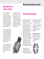
Measuring with the total station
Extrapolating a straight line
Polar setting-out of a point
Plumbing down from a height point
Surveys (polar method)
16
16
16
17
18
9
Measuring distances without a reflector
Automatic target recognition
Setting out profile boards
19
19
20
Instrument errors
Inspecting the line of sight
Inspecting the EDM of the total station
Instrument errors in the total station
22
22
23
24
Simple surveying tasks
Aligning from the mid-point
Measuring slopes
Measuring right-angles
26
26
27
28
Applications programs
Calculating areas
Staking out
Remote heights
Tie distances
Free-station surveys
29
29
30
31
32
33
The applications programs available
34
Surveying with GPS
35
3
The level
A level essentially
comprises a telescope
rotatable about a vertical
axis; it is used to create
a horizontal line of sight
so that height differences
can be determined
and stakeouts can be
performed.
The Leica Geosystems
levels are also equipped
with a horizontal circle that
is very useful for setting
out right angles, e.g. during
the recording of transverse
profiles. In addition, these
levels can be used to
determine distances
optically with an accuracy
to 0.1 – 0.3 metres.
4
The level • The total station
The total station
A total station consists of a
theodolite with a built-in
distance meter (distancer),
and so it can measure
angles and distances at the
same time. Today’s
electronic total stations all
have an opto-electronic
distance meter (EDM) and
electronic angle scanning.
The coded scales of the
horizontal and vertical
circles are scanned
electronically, and then the
angles and distances are
displayed digitally. The
horizontal distance, the
height difference and the
coordinates are calculated
automatically and all
measurements and
additional information can
be recorded.
Leica total stations are
supplied with a software
package that enables
most survey tasks to be
carried out easily, quickly
and elegantly. The most
important of these programs are presented in
the section "Applications
programs".
Total stations are used
wherever the positions
and heights of points, or
merely their positions,
need to be determined.
5
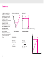
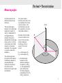
Coordinates
In order to describe the
position of a point, two
coordinates are required.
Polar coordinates need a
line and an angle.
Cartesian coordinates need
two lines within an
orthogonal system.
The total station measures
polar coordinates; these
are recalculated as
Cartesian coordinates
within the given
orthogonal system, either
within the instrument itself
or subsequently in the
office.
Direction of reference
Abscissa (x)
P
y
D
P
x
α
Ordinate (y)
Polar coordinates
Cartesian coordinates
X
Recalculation
Y
given: D, α
required: x,y
given: x,y
required: D, α
y = D sin α
x = D cos α
D = ÷ √y2 + x2
sin α = y/D or
cos α = x/D
P
D
X
α
Y
6
The level • The total station
Measuring angles
An angle represents the
difference between two
directions.
The horizontal angle α
between the two directions
leading to the points P1
and P2 is independent of
the height difference
between those points,
provided that the telescope
always moves in a strictly
vertical plane when tilted,
whatever its horizontal
orientation. This stipulation
is met only under ideal
conditions.
The vertical angle (also
termed the zenith angle) is
the difference between a
prescribed direction
(namely the direction of
the zenith) and the
direction to the point under
consideration.
The vertical angle is
therefore correct only if the
zero reading of the vertical
circle lies exactly in the
zenith direction, and also
this stipulation is met only
under ideal conditions.
Deviations from the ideal
case are caused by axial
errors in the instrument
and by inadequate
levelling-up (refer to
section: "Instrument
errors").
Zenith
P1
Z1
Z2
Z1 = zenith angle to P1
Z2 = zenith angle to P2
P2
α
α = Horizontal angle
between the two
directions leading to
the points P1 and P2,
i.e. the angle between
two vertical planes
formed by dropping
perpendiculars from P1
and P2 respectively
7
Setting up
the instrument
anywhere
1. Extend the legs of the
tripod as far as is
required and tighten the
screws firmly.
2. Set up the tripod so that
the tripod plate is as
horizontal as possible
and the legs of the
tripod are firm in the
ground.
3. Now, and only now,
place the instrument on
the tripod and secure it
with the central fixing
screw.
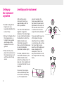
Levelling-up the instrument
After setting up the
instrument, level it up
approximately with the
bull’s-eye bubble.
Turn two of the footscrews
together in opposite
directions. The index finger
of your right hand indicates
the direction in which the
bubble should move
(illustration, top right).
Now use the third footscrew
to centre the bubble
(illustration, bottom right).
To check, rotate the instrument 180°. Afterwards, the
bubble should remain
within the setting circle. If it
does not, then readjustment
is required (refer to the user
manual).
For a level, the compensator automatically takes
care of the final levellingup. The compensator
8
consists basically of a
thread-suspended mirror
that directs the horizontal
light beam to the centre of
the crosshair even if there
is residual tilt in the telescope (illustration, bottom).
If now you lightly tap a leg
of the tripod, then (provided the bull’s-eye bubble
is centred) you will see how
the line of sight swings
about the staff reading and
always steadies at the
same point. This is the
way to test whether or not
the compensator can swing
freely.
A
B
C
A
B
C
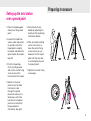
Preparing to measure
Setting up the total station
over a ground point
1. Place the tripod approximately over the ground
point.
2. Inspect the tripod from
various sides and correct
its position so that the
tripod plate is roughly
horizontal and above the
ground point (illustration,
top left).
3. Push the tripod legs
firmly into the ground
and use the central fixing
screw to secure the
instrument on the tripod.
5. Centre the bull’s-eye
bubble by adjusting the
lengths of the tripod legs
(illustration below).
6. After accurately levelling
up the instrument, release the central fixing
screw so that you can
displace it on the tripod
plate until the laser dot
is centred precisely over
the ground point.
7. Tighten the central fixing
screw again.
4. Switch on the laser
plummet (or, for older
instruments, look
through the optical
plummet) and turn the
footscrews so that the
laser dot or the optical
plummet is centred on
the ground point
(illustration, top right).
9
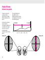
Height difference
between two points
The basic principle of
levelling involves
determining the height
difference between two
points.
To eliminate systematic
errors related to
atmospheric conditions or
to residual line-of-sight
error, the instrument
should be about
equidistant from the two
points.
Reading: 2.521
The height difference is
calculated from the
difference between the two
staff readings for the points
A and B respectively.
R = backsight
V = foresight
B
A
∆H = R -V = 2.521 - 1.345 = 1.176
Reading: 1.345
27
15
26
14
25
13
24
12
23
11
10
Measuring with the level
Measuring distances optically
with the level
The reticle carries two
stadia lines arranged
symmetrically to the
crosshair. Their spacing is
such that the distance can
be derived by multiplying
the corresponding staff
section by 100. (This
diagram is a schematic
representation).
Example:
Reading on upper
stadia line
B = 1.829
Reading on lower
stadia line
A = 1.603
Staff section
I = B-A = 0.226
Distance = 100 I = 22.6 m
B
A
Accuracy of the distance
measurement:
10 – 30 cm
D
11
Line levelling
If the points A and B are
widely separated, the
height difference between
them is determined by line
levelling with target
distances generally
between 30 and 50 metres.
Pace out the distances
between the instrument
and the two staffs; they
need to be about the same.
1. Set up the instrument
at S1.
2. Set up the staff precisely
vertically at point B; read
off and record the height
(backsight R).
4. Set up the instrument at
S2 (the staff remains at
the turning point 1).
R
5. Carefully rotate the staff
at the turning point 1 so
that it faces the
instrument.
6. Read off the backsight
and continue.
The height difference
between A and B is equal
to the sum of the backsight
and the foresight.
12
R
R
V
V
B
S1
A
Station
S1
S2
S3
∆H
Point
no.
A
A
1
1
2
2
B
H
S3
1
S2
Sum
3. Set up the staff at the
turning point 1 (ground
plate or prominent
ground point); read off
and record the height
(foresight V).
V
2
Backsight R Foresight V Height
Remarks
420.300
+2.806
-1.328
421.778
-3.376
419.321
-1.623
-6.327
421.113
= height A+R-V
+0.919
+3.415
+7.140
-6.327
+0.813
+0.813 = height B – height A
= height difference AB
∆H
Measuring with the level
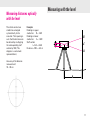
Staking out point heights
In an excavation, a point B
is to be set out at a height
∆H = 1.00 metre below
street level (Point A).
1. Set up the level so that
the sighting distances to
A and B are about the
same.
2. Set up the staff at A
and read off the
backsight R = 1.305.
In another frequently-used
method, the required staff
reading is calculated in
advance:
V= R - ∆H = 1.305 - (-1.000)
= 2.305
The levelling staff is then
moved upwards or downwards until the required
value can be read off with
the level.
9
9
9
9
9
9
9
9
9
9
9
9
9
9
9
9
9
9
9
9
9
9
9
9
9
9
9
9
9
9
9
9
9
9
A
B
3. Set up the staff at B
and read off the foresight
V = 2.520.
The difference h from the
required height at B is
calculated as:
h = V – R - ∆H = 2.520 –
1.305 – 1.00 = +0.215m
4. Drive in a post at B and
mark the required height
(0.215m above ground
level).
V=2.520
R=1.305
A
∆H= 1.00 m
∆H
B
h= +0.215 m
13
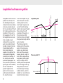
424.00
Longitudinal profile
(planned)
25 m
Reference height: 420 m
423.50
424.00
200
175
150
Transverse profile 175
Reference height: 420 m
Terrain
423.50
Roadline
125
14
instrument height. First, position the staff at a known
station point; the instrument height comprises the
sum of the staff reading
and the station point height.
Now subtract the staff
readings (at the points on
the transverse profile)
from the instrument height;
this gives the heights of the
points involved.
The distances from the
station point to the various
points in the transverse
profiles are determined
either with the surveyor’s
tape or optically using the
level. When representing a
longitudinal profile graphically, the heights of the
station points are expressed
at a much bigger scale (e.g.
10x greater) than that of
the stationing of the longitudinal direction, which is
related to a round reference
height (illustration above).
100
Longitudinal and transverse
profiles form the basis for
the detailed planning and
stakeout of communications
routes (e.g. roads) and also
for the calculation of fill and
for the best possible accommodation of the routes to
the topography. First of all
the longitudinal axis (roadline) is staked out and
stationed; this means that
points are established and
marked at regular intervals.
A longitudinal profile is
then created along the
roadline, the heights of the
station points being determined by line levelling. At
the station points and at
prominent topographic features, transverse profiles (at
right-angles to the roadline)
are then recorded. The
ground heights for the
points in the transverse
profile are determined with
the aid of the known
(planned height)
Longitudinal and transverse profiles
Measuring with the level
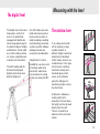
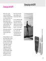
The digital level
The digital levels from Leica
Geosystems are the first
ones in the world to be
equipped with digital electronic image processing for
the determination of heights
and distances; the bar code
on a staff is read by electronic means, completely automatically (see illustration).
The staff reading and the
distance are displayed
digitally and can be recorded; the heights of
the staff stations are calculated continuously and so
there can be no errors related to reading, recording
and calculating. Leica Geosystems can offer software
packages for post-processing the recorded data.
A digital level is recommended for use where a lot
of levelling needs to be
carried out; under these
circumstances the saving
in time can amount to 50%.
The rotation laser
If, on a large construction
site for example, a large
number of points at
different heights need to be
staked out or monitored,
it often makes sense to use
a rotation laser. In this type
of instrument, a rotating
laser beam sweeps out a
horizontal plane, which
serves as the reference
plane for staking out or
monitoring heights such as
four-foot marks.
A detector is slid down a
levelling staff until it
encounters the laser beam;
the height can then be read
directly from the staff.
There is no need for an
observer at the instrument
station.
15
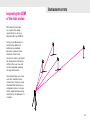
Extrapolating a straight line
Polar setting-out of a point
1. Position the instrument
at point B.
The setting-out elements
(angle and distance) here
relate to a known point A
and to a known starting
direction from A to B.
2. Target point A, transit the
telescope (i.e. reverse it)
and mark point C1.
3. Turn the instrument 200
gon (180°) and target
point A again.
4. Transit the telescope
again and mark the point
C2. Point C, the mid-point
between C1 and C2,
corresponds exactly to
the extrapolation of the
line AB.
A line-of-sight error is responsible for the discrepancy between C1 and C2.
Where the line of sight is in
order, the influence of the
errors is a combination of
target error, tilting-axis
error and vertical-axis error.
1. Set up the instrument
at point A and target the
point B.
2. Set the horizontal circle
to zero (refer to the user
manual).
3. Rotate the instrument
until a appears in the
display.
4. Guide the reflector
carrier (person) into and
along the line of sight of
the telescope, continually
measuring the horizontal
distance until point P is
reached.
B
C1
C
A
P
B
C2
α
D
A
16
Measuring with a total station
Plumbing down from a height point
Plumbing down from a
height point, plumbing up
from a ground point, and
inspecting a vertical line on
a structure, can be carried
out exactly in just one telescope face, but only if the
telescope describes a precisely-vertical plane when
it is tilted. To ascertain
that this is so, proceed as
follows:
The mid-point between the
points B and C is the exact
plumbing point.
The reason why these two
points do not coincide can
be a tilting-axis error
and/or an inclined vertical
axis.
For work of this type, make
sure that the total station
has been levelled up precisely, so that the influence
of vertical-axis tilt on steep
sights is minimized.
A
1. Target a high point A,
then tilt the telescope
downwards and mark the
ground point B.
2. Transit the telescope,
and repeat the procedure
in the second face. Mark
the point C.
B
C
17
Surveys (polar method)
To create e.g. a location
plan, the position and
height of a point on the
object are determined by
measuring angles and
distances. To do this, the
instrument is set up on
any prominent point in a
local coordinate system.
A second prominent point
is selected for the purposes
of orientation; after this
has been targeted the
horizontal circle is set to
zero (refer to the user
manual).
If a coordinate system
already exists, set up the
instrument on a known
point within it and line up
the horizontal circle with
a second known point
(refer to the user manual).
18
Measuring with the total station
Measuring distances
without a reflector
Each of the TCR total
stations from Leica
Geosystems includes not
only a conventional infrared distancer that measures to prisms, but also an
integrated laser distancer
that requires no reflector.
You can switch between
these two distancers.
This arrangement brings
many advantages where
points are accessible only
with difficulty or not at all,
for example during the
recording of frontages, in
positioning pipes and
for measurements across
gorges or fences.
The visible red laser dot is
also suitable for marking
targets in connection with
the recording of tunnel
profiles or with indoor
work.
The "DISTO" hand-held
laser meter from Leica
Geosystems is another
simple instrument that
uses a visible laser beam
and needs no reflector; it is
particularly suitable for
indoor measurements to
ascertain spacings, areas
and volumes.
Automatic target recognition
The TCA total stations from
Leica Geosystems are
equipped with an automatic
target-recognition system
("ATR"). This makes targeting faster and easier. It is
enough to point the telescope approximately at the
reflector; a touch on a
button then automatically
triggers the fine pointing
and the angle- and distance
measurements, and records
all of the values. This
technology also makes it
possible to carry out fullyautomatic measurements
with the help of a computer.
after establishing the initial
contact with the target the
instrument locks on to it
and tracks it. The practical
applications of this option
include the precise
guidance of construction
machinery.
Advantages of ATR: High
speed of measurement,
combined with a constant
measuring accuracy that
is independent of the
observer.
The ATR can also be
switched to a mode in
which moving targets can
be followed and measured;
19
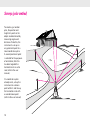
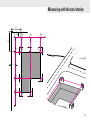
Setting out profile boards
During building alignment,
it is useful to extrapolate
the sides of the building to
beyond the limits of the excavation and there to erect
profile boards on which the
extensions are marked
exactly by hammering in
nails. These can be connected to strings or wires at
any time during the construction sequence, indicating the required
positions of the walls.
In the following example,
profile boards are to be
erected parallel to the proposed walls of a large
building and at distances of
a and b respectively from
the boundaries (illustration,
left).
1. Establish a baseline AB
parallel to the left-hand
boundary and at a freelyselectable distance c.
20
2. Mark the point A at the
defined distance d from
the upper boundary; it
will be the first location
for the total station.
6. The points on the profile
boards are then set out
in a similar manner,
starting from the points
A1 to A6 respectively.
3. Using a boning rod, mark
the point B at the end of
the baseline.
If the foundations have not
yet been excavated, you
can set out the sides H1H2
and H1H3 of the building
directly and use them as
the starting line for
marking the points on the
profile boards.
4. Set up the total station on
point A, target point B,
and set out the points A1,
A2 and A3 in this alignment in accordance with
the planned length of the
side of the building.
5. With point B sighted, set
the horizontal circle to
zero, turn the total station
by 100 gon (90°) and set
out the second line AC
with the points A4, A5
and A6.
For smaller buildings it is
easier to set out the profile
boards using an optical
square (right-angle prism)
and a measuring tape.
A building-alignment
software program
incorporated into many
Leica total stations enables
profile boards to be set out
directly, starting with any
instrument station.
Measuring with the total station
a
d
A
A4
A5
A6
b
A1
H1
H3
c
A2
A3
H2
B
21
Inspecting the line of sight (two-peg test)
In new levels, the compensator has been adjusted
at room temperature, so
that the line of sight is horizontal even if the instrument is tilted slightly. This
situation changes if the
temperature fluctuates by
more than ten or fifteen
degrees, after a long journey, or if the instrument is
subjected to strong vibration. It is then advisable to
inspect the line of sight,
particularly if more than
one target distance is
being used.
1. In flat terrain, set up two
staffs not more than 30
metres apart.
2. Set up the instrument
so that it is equidistant
from the two staffs (it
is enough to pace out the
distance)
22
3. Read off from both staffs
and calculate the height
difference (illustration
above).
Staff reading A = 1.549
Staff reading B = 1.404
∆H = A – B
= 0.145
1.549
1.404
4. Set up the instrument
about one metre in front
of staff A and take the
staff reading (illustration
below).
Staff reading A = 1.496
5. Calculate the required
reading B:
Staff reading A = 1.496
- ∆H
= 0.145
Required reading
B = 1.351
6. Take the staff reading B.
If it differs from the
required reading by more
than 3mm, adjust the line
of sight (refer to
instruction manual).
B
A
d
∆H
d
30m
Ist 1.496
Actual
Soll
1.3511.351
Required
A
B
∆H
Instrument errors
Inspecting the EDM
of the total station
Permanently mark four
runs within the range
typical for the user (e.g.
between 20 m and 200 m).
Using a new distancer, or
one that has been calibrated on a standard
baseline, measure these
distances three times.
The mean values, corrected
for atmospheric influences
(refer to the user manual)
can be regarded as being
the required values.
Using these four runs, measure with each distancer
at least four times per year.
Provided that there are no
systematic errors in excess
of the expected measuring
uncertainty, the distancer is
in order.
23
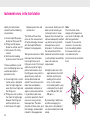
Instrument errors in the total station
Ideally, the total station
should meet the following
requirements:
a) Line of sight ZZ perpendicular to tilting axis KK
b) Tilting axis KK perpendicular to vertical axis VV
c) Vertical axis VV strictly
vertical
d) Vertical-circle reading
precisely zero at the zenith
If these conditions are not
met, the following terms are
used to describe the
particular errors:
a) Line-of-sight error, or collimation error c (deviation
from the right angle between the line of sight and
the tilting axis)
b) Tilting-axis error a (deviation from the right angle
between the tilting axis
and the vertical axis)
c) Vertical-axis tilt (angle
24
between plumb line and
vertical axis).
user manual. Vertical-axis tilt
does not rate as being an
instrument error; it arises
The effects of these three
because the instrument has
errors on the measurement
not been adequately levelled
of horizontal angles increase up, and measuring in both
with the height difference
telescope faces cannot
between the target points.
eliminate it. Its influence on
the measurement of the
Taking measurements in both horizontal and vertical angles
telescope faces eliminates
is automatically corrected by
line-of-sight errors and
means of a two-axis
tilting-axis errors. The line-of- compensator.
sight error (and, for highlyprecise total stations, also
d) Height-index error i (the
the tilting-axis error, which is
angle between the zenith
generally very small) can
direction and the zero
also be determined and
reading of the vertical
stored. These errors are then
circle, i.e. the verticaltaken into consideration
circle reading when using
automatically whenever an
a horizontal line of sight),
angle is measured, and then
is not 100 gon (90°), but
it is possible to take mea100 gon + i.
surements practically free of
error even using just one
By measuring in both faces
telescope face. The deterand then averaging, the
mination of these errors, and index error is eliminated; it
their storage, are described
can also be determined and
in detail in the appropriate
stored.
Note:
The instrument errors
change with temperature,
as a result of vibration, and
after long periods of
transport. If you want to
measure in just one face,
then immediately before
the measurements you
must determine the
instrument errors and store
them.
V
Z
K
Z
K
V
Instrument errors
i
Vertical-axis tilt
Height-index error (i)
(V index)
c
Line-of-sight error (c)
(Hz collimation)
a
Tilting-axis error (a)
25
Aligning from the mid-point
If intermediate points are
to be aligned within a line
of measurement and each
of the two end points
cannot be seen from the
other, proceed as follows:
4. From point 3, align point
4 in the straight line 3 – A
and continue in the same
manner until no further
lateral deviations are
visible at the two intermediate points.
1. Select two points 1 and 2
(both approximately in
the alignment) from
which both end points A
and E are visible. Use
sight poles to mark the
points.
2. From point 1, align point
2 in the straight line 1 – A
A
3. From point 2, align point
3 in the straight line 2 – E
1
2
3
4
26
E
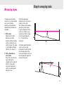
Simple surveying tasks
Measuring slopes
If slopes are to be determined in % or to be staked
out, e.g. for gutters,
pipelines or foundations,
two different methods are
available.
1. With a level
Measure the height
difference and the
distance (either optically
with the stadia hairs or
with the tape). The slope
is calculated as follows:
100 ∆H / D = slope in %
2. With a theodolite or
total station
Place the instrument on
a point along the
straight line the slope of
which is to be determined, and position a
staff at a second point
along that line.
Using the telescope,
determine the instrument
height i at the staff.
The vertical-circle reading
giving the zenith angle
in gon or degrees can be
reset to % (refer to user
manual) so that the slope
can be read off directly
in %. The distance is
irrelevant.
∆H
D
A reflector pole fitted with
a prism can be used
instead of the staff. Extend
the reflector pole to the
instrument height i and use
the telescope to target the
centre of the prism.
V%
i
i
27
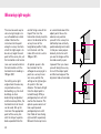
Measuring right-angles
The most accurate way to
set out a right-angle is to
use a theodolite or a total
station. Position the
instrument on the point
along the survey line from
which the right-angle is to
be set out, target the end
point of the survey line, set
the horizontal circle to zero
(see user manual) and turn
the total station until the
horizontal circle reading is
100 gon (90°).
For setting out a rightangle where the accuracy
requirements are less
demanding, e.g. for small
buildings or when
determining longitudinal
and transverse profiles, the
horizontal circle of a level
can be used. Set up the
level over the appropriate
point of the survey line
with the help of a plumb
bob suspended from the
28
central fixing screw of the
tripod. Then turn the
horizontal circle by hand to
zero in the direction of the
survey line or of the
longitudinal profile. Finally,
turn the level until the
index of the circle is set to
100 gon (90°).
An optical square is the
best solution for the
orthogonal surveying of a
point on a survey line or
vice versa, and for the
setting out at right-angles
of a point in the near
distance. The beam of light
from the object point is
turned through 90° by a
pentagonal prism so that it
reaches the observer. The
optical square consists of
two superimposed
pentagonal prisms with
their fields of view facing
right and left respectively.
Between the two prisms is
an unrestricted view of the
object point. You as the
observer can position
yourself in the survey line
(defined by two verticallypositioned alignment rods)
in that you move perpendicularly to the line until
you see the images of the
two rods exactly superimposed. Then you move
yourself along the survey
line until the object point
and the two images of the
alignment rods all coincide.
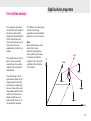
Applications programs
Calculating areas
1. Set up the total station
in the terrain so that it is
within view of the entire
area to be surveyed. It is
not necessary to position
the horizontal circle.
2. Determine the boundary
points of the area
sequentially in the
clockwise direction. You
must always measure a
distance.
3. Afterwards, the area is
calculated automatically
at the touch of a button
and is displayed.
B
A
C
D
29
Staking out
1. Set up the instrument at
a known point and
position the horizontal
circle (refer to the section "Setting the station”
in the user manual).
2. Enter manually the coordinates of the point to be
staked out. The program
automatically calculates
direction and distance
(the two parameters
needed for staking out).
3. Turn the total station
until the horizontal circle
reads zero.
Alternatively, the coordinates of the points to be
staked out can be transferred beforehand, back in
the office, from the
computer to the total
station. Under these
circumstances, in order to
stake out, only the point
number then needs to be
entered.
N
4. Position the reflector at
this point (point P’).
5. Measure the distance;
the difference in the
distance ∆D to the point
P will be displayed
automatically.
30
∆D
α
P'
P
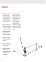
Applications programs
Remote heights
1. Set up a reflector vertically beneath that point
the height of which is to
be determined. The total
station itself can be
situated anywhere.
2. Measure the distance to
the reflector.
3. Target the high point.
H
4. The height difference H
between the ground
point and the high point
is now calculated at the
touch of a button and is
displayed.
31
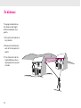
Tie distances
The program determines
the distance and height
difference between two
points.
1. Set up the total station at
any location.
2. Measure the distance to
each of the two points A
and B.
3. The distance D and the
height difference H are
displayed at the touch of
a button.
32
D
H
A
B
Applications programs
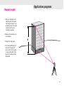
Free-station surveys
This program calculates
the position and height of
the instrument station,
along with the orientation
of the horizontal circle,
from measurements to at
least two points, the
coordinates of which are
known.
The coordinates of the tie
points can be entered
manually or they can be
stored in the instrument
beforehand.
Free stationing has the
great advantage that, for
large projects involving
surveying or staking out,
you can choose the most
favourable station for the
instrument. You are no
longer forced to use a
known point that is in an
unsatisfactory location.
The options for measuring,
and the measuring
procedure, are described in
detail in the user manuals.
Note:
When performing survey
tasks that involve
determining heights or
staking them out, always
remember to take the
height of the instrument
and that of the reflector
into account.
Hz=0
H
N (x)
E (y)
33
The applications programs available
Recording points
Orientation and
height transfer
Resection
Tie distance
Staking out
Remote heights
Free-station surveys
Reference line
Hidden points
Area computation
Sets of angles
Traversing
Local resection
COGO (computations)
Automatic storage
Scanning surfaces
Digital terrain models
Offset
34
Surveying with GPS
Surveying with GPS
GPS surveys use the
signals transmitted by
satellites having trajectories
such that any point on the
Earth’s surface can be
determined around the
clock and independently of
weather conditions. The
positioning accuracy
depends on the type of
GPS receiver and on the
observation and postprocessing techniques
used.
tasks that until recently
were carried out using
electronic total stations.
The new GPS System 500
from Leica Geosystems
enables the most diverse
range of survey tasks to be
carried out with centimetre
accuracy – on the tripod;
on the plumbing pole; on
ships, vehicles and
construction plant; and
using both static and
kinematic applications.
Compared with the use of a
total station, GPS surveying
offers the advantage that
the points to be measured
do not have to be mutually
visible. Today, provided
that the sky is relatively
unobstructed (by trees,
buildings etc.) and therefore that adequate satellite
signals can be received,
GPS equipment can be
applied to many survey
35
Illustrations, descriptions and technical data are not binding and
may be changed. Printed in Switzerland.
Copyright Leica Geosystems AG, Heerbrugg, Switzerland, 2000
722510en – VII.00 – RVA
Leica Geosystems AG
CH-9435 Heerbrugg
(Switzerland)
Phone +41 71 727 31 31
Fax +41 71 727 46 73
www.leica-geosystems.com


![e-track User`s Manual [FW1.00]](http://vs1.manualzilla.com/store/data/005696177_1-79f2a7130a6208690505d356432cfe5f-150x150.png)