1
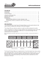
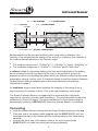
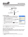
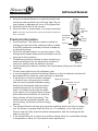
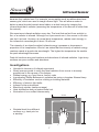
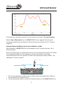
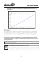
Smart
Q
TECHNOLOGY
Infrared Sensor
(Product No. 3278)
EFR-104
Wavelength region
Without filter 0.23 - 40 microns
With filter 0.23 - 4 microns
Ranges
Radiance: 0 - 30 W/m2 sr -1
Resolution: 0.02 W/m2 sr -1
Radiance: 0 - 300 W/m2 sr -1
Resolution: 0.2 W/m2 sr-1
Radiance: 0 - 3,000 W/m2 sr -1
Resolution: 2 W/m2 sr -1
Irradiance: 0 - 20 W/m2
Resolution: 0.01 W/m2
Irradiance: 0 - 200 W/m2
Resolution: 0.1 W/m2
DATA HARVEST
Data Harvest Group Ltd
1 Eden Court, Leighton Buzzard,
Beds, LU7 4FY
Tel: 01525 373666
Fax: 01525 851638
e-mail: [email protected]
www.data-harvest.co.uk
Irradiance: 0 - 2,000 W/m2
Resolution: 1 W/m2
DS 056
© Data Harvest. Freely photocopiable for use within the purchasers establishment.
No 3
Smart
Q
Infrared Sensor
TECHNOLOGY
Contents
Introduction....................................................................................................... Connecting....................................................................................................... To set the range................................................................................................ Using the silica glass filter................................................................................ Practical Information......................................................................................... Background...................................................................................................... Investigations................................................................................................... Using infrared radiation to locate a disaster victim..................................... Relationship between temperature and infrared energy............................. Warranty........................................................................................................... 1
2
3
3
4
6
7
8
9
10
Introduction
The sensing element in the Smart Q Infrared Sensor is a thermopile detector that
can be used to measure the intensity of total heat radiation.
The Infrared Sensors detector window is made from KBr (potassium bromide),
which is transparent to energy sources radiating in the wavelength region from 0.23
microns (230 nm) to 40 microns (40,000 nm) i.e. ultraviolet through to the far
infrared portion of the spectrum.
Note: KBr (potassium bromide) is hygroscopic so store in dry conditions - see practical information on
page 4.
UVA
Visible light
Near infrared
Mid infrared
Far infrared
0.1 – 0.4 μm
0.4 – 0.7 μm
0.75 – 3 μm
3 – 25 μm
25 – 1,000 μm
KBr
Lets through energy sources in the 0.23 - 40 ���������
μm region
0.23 μm (230 nm)
Wavelength
40 μm (40,000 nm)
The Smart Q Infrared Sensor is supplied with a 2 mm thick water-free vitreous silica
glass detachable filter. This filter will allow visible and near infrared to pass i.e. 0.15
microns (155 nm) to 4 microns (4,000 nm), but will block out mid and far infrared.
When this filter is fitted the sensitivity of the Sensor will be restricted from 0.23
microns to 4 microns.
Smart
Q
Infrared Sensor
TECHNOLOGY
0.4 - 0.7����
μm Visible
�������������
light
0.1 - 0.4�������
μm UVA
3 - 25����
μm ������������
Mid infrared
0.75 - 3����
μm �������������
Near infrared
0.23 ��
μm
40 ��
μm
KBr
0.15 ��
μm
4 μm
��
Glass filter
Lets through 0.23 - 4 �������������������������
μm (230 - 4,000nm) region
Measurements can be recorded at three levels using either a Radiance (the
intensity of the emitted thermal energy of the source) or Irradiance (the intensity of
the incident thermal radiation on the Sensor) range.
• The radiance ranges are 0 - 30 W/m2 sr-1, 0 - 300 W/m2 sr-1 and 0 - 3000 W/m2 sr-1.
• The irradiance ranges are 0 - 20 W/m2, 0 - 200 W/m2 and 0 - 2000 W/m2.
A radiance range is used when studying the heat emitting properties of a surface
and is normally used with the Sensor quite close to the source of energy. An
example would be investigating the radiant heat from different surfaces at the same
temperature using a Leslie’s cube. If a radiance range is used the distance between
Infrared Sensor and the radiating source becomes important, see practical
information on page 4.
An irradiance range is used when studying the intensity of the energy from a
source arriving at a surface or point. This is the most commonly used range.
The Smart Q Infrared Sensor is equipped with a microcontroller that greatly
improves its accuracy, precision and consistency. The microcontroller contains the
calibration for these six ranges. The stored calibration for the selected range is
automatically loaded into EASYSENSE when the Infrared Sensor is connected.
Connecting
•
•
•
Hold the Infrared Sensor housing with the Smart Q label showing on the top.
Push one end of the sensor cable (supplied with the EASYSENSE unit) into the shaped socket on the Sensor with the locating arrow on the cable facing upwards.
Connect the other end of the sensor cable to the input socket on the EASYSENSE unit (with the locating arrow facing upwards).
Smart
Q
Infrared Sensor
TECHNOLOGY
• The EASYSENSE unit will detect that the Infrared Sensor is connected and display values using the currently selected range. If the range is not suitable for EASY SENSE
your investigation, set to the correct
range.
POWER
SERIAL
DATA HARVEST
ENTER
METER
STOP
A
1
2
5
4
3
B
6
Input
socket
Smart
DATA HARVEST
Sensor cable locating
arrow facing upwards
TECHNOLOGY
Q
Infrared
sensor
To set the range
•
•
•
•
•
Connect the Infrared Sensor to the EASYSENSE unit.
Start the EASYSENSE program and select one of the
logging modes from the Home page. Select Sensor
Config. from the Settings menu.
Select the Infrared Sensor from the list (it will be listed
using its current range) and click on the Change Range
button.
The current range will be highlighted. Select the
required range and click on OK.
Close Sensor Config. Click on New
and then Finish
for the change in range to be detected by the logging
mode.
The range setting will be retained until changed by the user.
With some EASYSENSE units it is possible to set the range from the unit. Please
refer to the EASYSENSE unit’s user manual.
Using the silica glass filter
When the vitreous silica glass filter is fitted, it will alter the response of the Infrared
Sensor to give an effective range of 0.23 to 4 micron (230 - 4,000 μm). This will
allow visible and near infrared to pass, but will block out the mid and far infrared
portion of the spectrum.
To fit or remove the filter:
1. Unscrew and remove the end cap from the Sensor.
2. Place the glass filter inside the end cap so it rests on the small aperture
platform.
Q
Infrared Sensor
TECHNOLOGY
Note: The screw cap can be left on the Infrared Sensor when the
filter is not fitted.
Practical Information
Q
Keep the Infrared Sensor in a vertical position and
screw the end cap back on until finger tight. Do not
over tighten or damage will occur to the glass filter.
Removal of the filter is the reverse.
Store the filter in a safe place, it is easily scratched.
Smart
DATA HARVEST
3.
4.
5.
TECHNOLOGY
Smart
Detachable
silica glass
filter
Black
collimator
tube
KBr
detector
window
• Avoid moisture. The detector window (visible by
End cap
looking into the end of the collimator tube) is made
from KBr (potassium bromide) and has a tendency
Looking into the
to absorb moisture.
collimator tube
• Store the Infrared Sensor in a cool dry place. If the
KBr
storage area maybe damp add a desiccant such as
detector
silica gel to the container.
window
• Potassium bromide is soluble in polar solvents e.g.
water and ethanol. Do not allow polar solvents to
Screw cap
come into contact with the detector window.
•Avoid touching the detector window, this could cause pitting and will affect
readings.
• Do not insert objects into the collimator tube.
• In an investigation position the Infrared Sensor so that its detector window will be protected from moisture, polar solvents or particles.
• If the Sensor is used to monitor changes
Radiant heat source
in infrared over a long period a ‘shutter’
Cardboard covered
can be used to prevent radiated energy
in metal foil
heating the thermopile detectors when
measurements are not actively being
Infrared
taken. A suitable shutter can be made
sensor
from a piece of corrugated card covered
both sides with aluminium foil (with the
shiny surface of the foil showing). The
shutter should be placed between, but
not touching, the Sensor and the energy
source.
• The Infrared Sensor will only give accurate readings when the flow of energy
into the Sensor is greater than the flow out. For example, on a cold day the
Sensor may be hotter than the ambient temperature and the readings will be static or very low.
• If the Infrared Sensor is moved to a position where there is a noticeable change in temperature, leave for 5 minutes to reach equilibrium.
Smart
Q
Infrared Sensor
TECHNOLOGY
Collimator
iris
Radiant body
Infrared
sensor
l
Target area
Thermopile
KBr window
•
If a radiance range is used the distance between Infrared Sensor and the
radiating source becomes important. The Sensor will detect from an area that increases in size with the distance from the source. To ensure that
measurements are taken from the source rather than its surrounding area, the target area of the Infrared Sensor must be smaller than the radiating source i.e. the source must fill the field of view of the Sensor.
This table shows the Sensors’ target area at different distances.
Note: For convenience the distance measurements are taken from the shoulder of the Sensor housing.
At this distance from the shoulder
of the Sensor housing (mm)
The diameter of the target area is (mm)
20
20
25
25
30
30
40
45
50
55
60
70
70
80
80
90
90
100
100
115
110
125
120
140
130
150
140
165
150
175
Smart
Q
Infrared Sensor
TECHNOLOGY
Background
The sensing element in the Smart Q Infrared Sensor is a thermopile detector that
can be used to measure the intensity of total heat radiation.
The Infrared Sensor has several junctions between dissimilar metals connected in
series. When radiant energy strikes a junction a small flow of electrons is initiated,
the arrangement of the junctions creates a cascade effect and the electron flow is
amplified. The flow of electrons is proportional to the energy striking the Sensor.
The thermopile relies on there being a temperature difference between the front of
the junction and the back of the junction. As measurements are taken the
thermopile will heat up and the temperature difference between the front and back
will decrease. Readings will therefore be affected by prolonged exposure of the
Sensor to the radiant source. A ‘shutter’ can be used to reduce this effect, see
practical information on page 4.
Infrared
Infrared (IR) is invisible and is detected most often by its heating effect. It forms part
of the electromagnetic radiation spectrum. Electromagnetic radiation is a transfer of
energy through space via waves of oscillating electromagnetic fields. What
distinguishes the parts of the electromagnetic spectrum is the frequency of the
oscillation and consequently the wavelength. Infrared has a range of wavelengths
that are longer than those of visible light. Near infrared light is closest in wavelength
to visible light. Far infrared is closer to the microwave region of the electromagnetic
spectrum.
Infrared wavelengths are normally expressed in microns. There doesn’t seem to be
an agreed classification of infrared regions but for the purposes of this booklet we
refer to Near infrared as 0.75 microns - 3 microns (750 – 3,000 nm), Mid infrared as
3 - 25 microns (3,000 – 25,000 nm) and Far infrared as 25 – 1,000 microns (25,000
– 1,000,000 nm). Wavelengths of over 30 microns are virtually impossible to
measure, as the energy in the radiation is far too low.
When an object is not quite hot enough to radiate visible light, it will emit most of its
energy in the infrared. For example, when an electric fire is first switched on it does
not give of any light but will emit infrared radiation that we feel as heat. As more
electric energy is supplied, the fire will get hotter and it will begin to glow red (emit
visible radiation). The peak wavelength decreases as temperature increases, which
is why objects glow first red, then orange-red, and then yellow as they heat up.
Any object that has a temperature above absolute zero radiates in the infrared.
Even objects that we think of as being very cold, such as an ice, emit infrared.
Infrared detectors can see objects in the dark that we cannot see in visible light
Smart
Q
Infrared Sensor
TECHNOLOGY
because they radiate heat. For example, some reptiles such as rattlesnakes have
sensory pits, which are used to image infrared light. This will allow a snake to
detect a warm-blooded animal when hidden in a dark burrow by imaging the
infrared heat that it radiates (assuming the temperature of the burrow is colder than
the animal).
We experience infrared radiation every day. The heat that we feel from sunlight, a
fire, or a radiator is infrared. Although our eyes cannot see it, the nerves in our skin
can feel it as heat. Humans, at normal body temperature, radiate most strongly in
the infrared at a wavelength of about 10 microns.
The intensity of an object’s emitted infrared energy increases or decreases in
proportion to its temperature. Wien’s Law states that the intensity of radiant energy
reaches a peak at a particular wavelength. The higher the temperature the smaller
the peak wavelength becomes.
Dark dull surfaces are good emitters and absorbers of infrared radiation. Light shiny
surfaces are poor emitters and absorbers.
Investigations
•
•
•
•
•
•
•
•
•
•
Herschel’s discovery of infrared experiment
Study inverse square to verify that heat radiation from source is inversely
proportional to the square of its distance
Radiant energy e.g. heat from a Leslie’s cube
Investigating Stefan-Boltzmann’s radiation law using a tungsten filament lamp
Efficiency of insulation such as clothing or building materials
Efficiency of electric light bulbs
Infrared in the environment
Black body studies (radiance range)
Heat distribution along a heated metal rod
Illustration of non-contact thermometry
20 cm
• Residual heat from different
surfaces e.g. hand print on
a worktop
20 cm
Smart
Q
Infrared Sensor
TECHNOLOGY
This data was collected using the 5 minute activity worksheet, Thermal imaging.
[Select Open Worksheet from the EASYSENSE Home page ► Data Harvest
Investigations ►Workroom files ► 5 Minute Activities and select No 06, Thermal
imaging].
Using infrared radiation to locate a disaster victim
[Also available in EASYSENSE as a Worksheet in the 5 minute Activities - No 5,
Find the body!].
Rescue workers may use infrared devices to try to find survivors buried in the rubble
of a collapsed building. In this experiment you will use bottles of hot water
(simulating heat from a live ‘person’) buried under polystyrene chips (rubble) - the
challenge is to find a ‘person’.
Sealed bottle of hot water
Polystyrene chips
1. Set up the apparatus as shown above. Remove the silica glass filter if fitted to the end cap of the Infrared Sensor.
2. Use a long sensor lead to connect the Infrared Sensor to the EASYSENSE unit.
Smart
Q
Infrared Sensor
TECHNOLOGY
3. Open the EASYSENSE program and select Meters from the Home page. The
numeric window should show either Rad 30 or Irrad 20 (W/m2), if not change the range. Make the window full size.
4. Move the Infrared Sensor over the ‘disaster area’ slowly and start a logical search pattern to find any ‘hot spots’ (the measurements will raise significantly if a hot body is detected).
5.Mark any hot areas with a flag. When you have covered the whole area ‘dig’ down to find the survivors.
Relationship between temperature and infrared energy
The Austrian scientist Josef Stefan found there was a relationship between the
amount of radiant energy emitted from a surface and its temperature. In this
investigation you will measure the surface temperature of a can e.g. Leslies cube,
filled with hot water and the radiant energy emitted. If the energy emitted is related
to the temperature, a plot of energy vs. temperature will reveal the relationship.
1. Set up the apparatus as shown. Remove the
silica glass filter if fitted to the end cap of the
Infrared Sensor. Connect the Infrared and
Temperature Sensor to the EASYSENSE unit. Temperature
Heat sink
2. Open the EASYSENSE program and select
sensor
compound
Graph from the Home page. From the
Logging Wizard select a 5 minute recording
Infrared
time.
sensor
3. The Infrared Sensor should be set to an
appropriate radiance range e.g. Rad 300
(W/m2).
4. Fix the Temperature Sensor against the matt
l
black outer surface of the can - make sure a
Matt
good contact is made (if you have any heat
black surface
sink compound then this will help).
5. Select Test mode from the Tools menu and fill the can with water that has just boiled.
6. Position the Infrared Sensor close too and pointing at the can. The target area of the Sensor must be fully covered by the can (see practical information on 4). Check that the reading from the Infrared Sensor is within range. If not change to a more suitable range.
7. Click on the Start icon to begin recording.
8. When the recording has stopped plot an X/Y graph from the collected data of Infrared (energy) against temperature i.e.
• Select X-Axis from the Display menu and select as Channel, OK.
• Click to the left of the Y-axis until Infrared is displayed. Click below the X-axis until Temperature is displayed. Right click in the graph area and select Auto
scale graph Min Max.
Smart
Q
Infrared Sensor
TECHNOLOGY
• A straight-line graph will indicate a direct relationship between energy and temperature.
Warranty
All Data Harvest Sensors are warranted to be free from defects in materials and
workmanship for a period of 12 months from the date of purchase provided they
have been used in accordance with any instructions, under normal laboratory
conditions. This warranty does not apply if the Sensor has been damaged by
accident or misuse.
In the event of a fault developing within the 12-month period, the Sensor must be
returned to Data Harvest for repair or replacement at no expense to the user other
than postal charges.
Note: Data Harvest products are designed for educational use and are not intended for use in industrial,
medical or commercial applications.
WEEE (Waste Electrical and Electronic Equipment) Legislation
Data Harvest Group Ltd are fully compliant with WEEE legislation and are pleased to provide a disposal service for any of our products when their life expires. Simply return them to us clearly identified as ‘life expired’ and we will dispose of them for you.
10