1
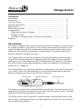
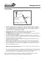
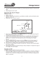
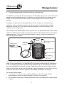
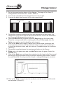
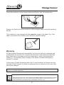
Smart
Q
TECHNOLOGY
Charge Sensor
(Product No. 3268)
Charge Ranges:
•
•
•
±10 nCoulomb (nC)
Resolution: 0.01 nC
±100 nCoulomb (nC)
Resolution: 0.1 nC
±220 nCoulomb (nC)
Resolution: 1 nC
Voltage Ranges:
•
•
•
±0.5 V (500 mV)
Resolution: 0.001 V
±2 V
Resolution: 0.01 V
±10 V
Resolution: 0.01 V
DATA HARVEST
Data Harvest Group Ltd
1 Eden Court, Leighton Buzzard,
Beds, LU7 4FY
Tel: 01525 373666
Fax: 01525 851638
e-mail: [email protected]
www.data-harvest.co.uk
DS 059
© Data Harvest. Freely photocopiable for use within the purchasers establishment.
No 2
Smart
Q
Charge Sensor
TECHNOLOGY
Contents
Introduction............................................................................................... Connecting............................................................................................... To set the range........................................................................................ Practical information................................................................................. Specifications........................................................................................... Subtracting an offset................................................................................. Investigations........................................................................................... Determine the sign of charges............................................................ Faraday Ice Pail.................................................................................. Information: Charging a disc conductor by induction.......................... Warranty ................................................................................................ 1
2
3
3
5
5
5
6
6
9
10
Introduction
The Smart Q Charge Sensor can measure the amount of charge on a source where
the charge available is very small e.g. as in many electrostatic experiments. It can
replace a traditional gold leaf electroscope by showing not only the polarity of the
charge but also performing quantitative measurements. It can also measure the
potential difference between two points.
The Charge Sensor has an input capacitor connected in parallel across the input
terminals to a voltage amplifier. An applied charge will charge the input capacitor
resulting in a rise in the magnitude of the voltage across the capacitor. The Sensor
will use the value of the potential difference across the capacitor to calculate the
charge (nC) or voltage (V).
The Charge Sensor is a very high impedance voltage sensor (at least 10 tera ohms
(1012 ohms), which will draw practically no current whilst measuring the potential
difference between the ends of an electrical component.
Power on LED
Reset Ground button
BNC/crocodile lead
The Sensor is supplied with a shielded BNC/crocodile lead. This lead should not be
substituted by another manufacturer’s lead, which could give false results. The lead
ends with a red and black (earth) crocodile clip.
The Sensor has an LED to indicate it is powered and a reset ground button, which
can be used to discharge the Sensor’s input capacitor (so there is no need to short
the crocodile clips together).
Smart
Q
Charge Sensor
TECHNOLOGY
Connecting
Input socket
Smart Q
label on top
Sensor cable with
locating arrow
facing upwards
Align marks, push in and
rotate the BNC connector
•
•
•
•
•
•
•
•
Hold the Charge Sensor housing with the Smart Q label showing on the top.
Push one end of a 150 mm short sensor lead (Product No 3004 - as supplied
with the EASYSENSE unit) into the shaped socket on the adapter with the
locating arrow on the lead facing upwards.
Connect the other end of the sensor lead to the input socket on the
EASYSENSE unit (with the locating arrow facing upwards).
The EASYSENSE unit will detect that the Charge Sensor is connected. Select the range required (see page 3).
Connect the BNC/crocodile lead (supplied) to the BNC socket on the sensor housing by lining up the BNC connector with the pins on the socket, push in and then turn clockwise to lock into place.
Discharge the Sensor’s internal capacitor by pressing the reset button on the adapter for about 2 seconds.
When measuring charge connect the black lead to a good earth-connecting point and the red lead to the object that is going to hold / is holding the charge.
Start the application you need for the investigation e.g. Graph and verify the Sensor is reading about zero.
Notes: There maybe a small residual voltage which can be subtracted from the final measurement to give a more accurate reading (see page 5).
• Due to the extremely high input impedance, the Charge Sensor will tend to pick up stray charges from its surroundings if left with nothing driving its inputs. If so, press the reset button to discharge before starting to record data.
After a recording short the object that is charged to earth and press the reset
ground button on the Sensor to discharge the internal capacitor.
Smart
Q
Charge Sensor
TECHNOLOGY
To set the range
•
•
•
•
Connect the Charge Sensor to the EASYSENSE unit.
Start the EASYSENSE program and select one of the
logging modes from the Home page e.g. EasyLog.
Select Sensor Config from the Settings menu.
Select the Charge Sensor from the list (it will be listed
using its current range) and click on the Change
Range button.
The current range will be highlighted. Select the
required range and click on OK. Close Sensor Config.
Click on New and then Finish for the change in
range to be detected by the logging mode.
The range setting will be retained until changed by the user. With some
EASYSENSE units it is possible to change the range from the unit. Please refer to
the EASYSENSE unit’s user manual.
Practical information
• The extremely high input resistance of this Sensor also makes it sensitive to
stray electrostatic fields in its immediate vicinity. To minimize the influence of static fields, follow these guidelines:
1.
2.
3.
4.
5.
6.
Better results are obtained if, whilst
conducting the investigation, the user
is connected to a good ground or earth
point. The electrostatic discharge
apparatus (e.g. wrist band, grounding
cord and earth bonding plug) used by
circuit board assemblers will provide a
good link to earth. Be careful not to
touch any voltage sources while you
are grounded.
If it isn’t possible for the user to connect to an earth point then they should keep as still as possible with their feet on the floor.
Movement from people or equipment in the locality can produce static, which will disrupt readings.
When conducting investigations where the quantity of charge needs to be measured accurately (and not comparatively) mount the Charge Sensor so it won’t be moved during an investigation e.g. in a retort stand and clamp
It is best to use the shorter sensor lead (150 mm long, Product No. 3004) to connect the Charge Sensor to an EASYSENSE unit.
The Charge Sensor is sufficiently sensitive to detect charge accumulation
on the leads if left connected to the EASYSENSE unit between taking
readings. Leave the crocodile clips at the end of the lead set connected Smart
Q
Charge Sensor
TECHNOLOGY
7.
8.
together (so they are shorted out) or press the reset button before collecting data.
In some circumstances wrapping the Sensor in aluminium foil may help stabilise readings.
Weather conditions can have an effect on readings. In dry weather keep body movement to a minimum to reduce the effect of stray static charge. In
humid weather the charge may leak too rapidly to get reasonable results from some investigations.
• Equipment used for static investigations must be clean and dry. It must be kept dry even whilst working under humid conditions. Putting the cloths, rods, and other equipment on a metal plate above a radiator works well. A warm air blower (e.g. a hairdryer) can be very useful.
• If the equipment being used proves difficult to discharge, breathe gently over it.
The moisture and heat in the breath will be enough to carry any remaining
charge away. A yellow Bunsen flame will discharge insulators very effectively, when used with care. The hot gases rising from the flame are ionised and will neutralise surface charge on insulators.
• The Charge Sensor will be affected by devices that use electromagnetic fields. The equipment that can produce interference includes computer monitors,
mobile phones, televisions, switching power supplies, electric motors, etc.
• Even after shorting out the terminals or pressing the reset button there can be a small offset voltage recorded (the reading may not be exactly at zero). This offset can be subtracted using a pre or post-log function (see page 5).
• The Sensor has over voltage protection of ±40 V, but this would be insufficient to protect the device from the extremely high voltages (in the thousands)
created by a Van de Graaff or similar high voltage generator.
• High frequency fluctuating fields (such as 50 Hz or above) will usually not be detectable. The Sensor has a low pass filter to ensure that any 50/60 Hz mains signal is attenuated. Input signals with a rise/fall time quicker than approximately 80 ms will be significantly reduced in value.
• When used to measure the potential difference between the ends of an
electrical component the Charge Sensor should be connected in parallel i.e. across the component.
• For reasons of accuracy, if the Charge Sensor is used with another Charge or Voltage Sensor in a circuit, ensure they share a common earth (the same black lead).
• The Charge Sensor can be used to measure DC circuits.
SAFETY: Never use with high voltages.
• The Charge Sensor can be used to look at low-voltage AC signals if the
following is followed: 1. The maximum voltage is 20 Vpp (peak to peak) i.e. low voltage, low frequency AC signals. It is not suitable for looking at mains supply voltages.
2. The maximum frequency is limited to 12 Hz.
Smart
Q
Charge Sensor
TECHNOLOGY
•
When measuring the charge on a capacitor, it is necessary to use capacitor
values significantly less than 22 nF. For good results use low current leakage capacitors below 1 nF. The error in this case will be less than 4.6%.The lower the value capacitor the more accurate the results.
The SI unit of electric charge is the Coulomb. It is equal to the amount of charge
which passes a point in a conductor if one ampere flows through the conductor for
one second.
Specifications
Input impedance: 1012 ohms, minimum
Input capacitance: 22 nF ±1% (0.022 µF)
Input voltage Range: ±10 V
Input over voltage protection: up to ±40 V
Subtracting an offset
A Pre or Post-log function can be used to subtract an offset from the Sensors
readings. Use the Pre-log function for the tare to be applied to the data as logging
progresses or the Post-log function to apply the tare to data that has already been
recorded.
•
•
•
Select Test Mode from the Tools menu to find the tare
value and then click on Stop.
Select Pre or Post-log function from the Tools menu.
Select a Preset function, with General from the dropdown list and then Tare from the second list, Next.
Select the Charge Sensor as the Channel, Next. Enter
a name for the corrected data set e.g. Charge (adj.)
and enter the tare value. Click on Finish.
Investigations
•
•
•
•
•
•
•
•
•
•
•
Magnitude and sign of the charge on different objects.
Electrostatic phenomena.
Simple demonstrations of sign of charge.
Charge sharing between conductors.
Faraday’s ice pail investigations.
Electrostatic shielding.
Induced charge.
Charging by induction.
Density of charge on the surface of a conductor.
Investigating the relationship ‘Voltage is proportional to the charge on an object’ by adding charges.
Discharge of a capacitor.
Smart
Q
Charge Sensor
TECHNOLOGY
• Use as a high impedance voltmeter e.g. measuring the voltage of chemical half cells.
• Measuring the emf of cells.
Determine the sign of charges
What you need:
• Duster, cloth, fur.
• Different objects and materials e.g. polythene, acetate, nylon and ebonite rods, balloons, pens, etc.
• Metal disc, coin or small ‘ice pail’.
Red lead
Black lead
Earthed lead
Charge Sensor
1.
2.
3.
4.
5.
6.
Metal disc, coin
or small ‘pail’
Attach the Charge Sensor to the EASYSENSE unit. The range of the Smart Q Charge Sensor should be set to 100 nC.
Connect the red lead from the Charge Sensor to a metal disc and hang from a clamp. Connect the black lead to ground. The ‘earthed lead’ can be used in
addition to or instead of the reset ground button to discharge the Charge
Sensor.
Open the EASYSENSE program and select Meters from the Home page. A Numeric window will open, click on maximise so the window fills the screen.
Discharge the Charge Sensor by pressing the reset ground button.
Bring up a charged object towards the metal disc. Observe and record the sign and charge reading.
Discharge the Sensor and repeat using a variety of objects. Compare the sign of the charge from each object.
Faraday Ice Pail
Faraday originally used his ice pail to show that:1. When a charged object is enclosed in a hollow conductor, it induces a charge on the inside of the conductor equal in size and opposite in sign to its own; on the outside of the conductor a charge equal in size, and of the same charge as the object, is induced.
Smart
Q
Charge Sensor
TECHNOLOGY
2. The total charge inside a hollow conductor is always zero.
In addition to proving the above principles, the Faraday ice pail is a useful device for
sampling and comparing charge. It operates on the principle that a charge placed
inside a conducting surface will induce an equal charge on the outside of that
surface.
Faraday’s ice pail was a modest pail about 27 cm tall and not a bucket-sized
container. Use a cylindrical container for the ice pail, the length of the cylinder
should be at least two, if not three times the diameter. It will work better if the
cylinder has a closed base.
We used an outer shield made from a cylinder of 1 cm galvanised steel metal mesh
(without a bottom). The metal ice pail is placed inside the shield with an even space
separating them. The ice pail should be placed on a non conductive platform (a
block of dry wood is ideal).
Charge Sensor
Even gap
between
ice pail
and shield
Black clip
connected
to shield
Red clip connected
to ice pail
Grounding wire
Ice pail
Wire mesh shield
Non conductive
platform e.g. block
of dry wood
The outer mesh cylinder is connected to ground and shields the ice pail, which is
used for the investigation. It is preferable for the person performing the experiment
to be continually grounded to prevent stray charges e.g. by continuously touching
the outer shield with one hand. A piece of wire secured to the mesh shield can be
used to ground the ice pail; the wire needs to be long enough to touch the lip of the
ice pail. It can also be used to ground or discharge conductors as needed.
You will also need either:
• A conductor mounted on an insulating handle e.g. the disc from a small
electrophorus, which can be charged by induction (see page 9).
• Or mounted, conducting ‘Charge producers’ which are charged by rubbing them together.
Smart
Q
Charge Sensor
TECHNOLOGY
1.
2.
3.
Set up the experiment as shown in the diagram. The range of the Smart Q Charge Sensor should be set to ±100 or ±220 nC.
Connect the red lead from the Charge Sensor to the ice pail.
Connect the black lead (ground) to the outer mesh shield.
Grounding wire
4.
5.
6.
7.
8.
9.
Ground the ice pail by touching with the wire attached to the wire shield. Any charge built up on the ice pail will travel across the wire to the outer shield then out to ground. Lift the ground wire back up.
Open the EASYSENSE program and select EasyLog from the Home page.
Press the reset ground button to discharge the Sensor (Test mode from the Tools menu can be used to check the value is zero).
Click on the Start icon to begin. Charge one of the mounted conductors and then insert the conductor into the lower part of the ice pail, without allowing it to touch the bottom or sides, and then remove. Do not discharge the conductor. (Result A)
Ground the ice pail and press the reset ground button on the Sensor.
Right click in the graph area and use Add Text to label the graph. Select the Overlay icon.
Click on the Start icon, and lower the conductor into the lower half of the ice pail but this time touch the inside of the ice pail so it makes a good contact, remove the rod (Result B). Do not ground the ice pail or charge/discharge to conductor.
10.Click on the Start icon and lower the conductor into the ice pail, touch the side and withdraw it (Result C).
Smart
Q
Charge Sensor
TECHNOLOGY
11.Ground the ice pail and repeat 10 (Result D).
12.Press reset on the Sensor. Ground the ice pail then repeat the investigation
using a conductor with the opposite charge.
Note: If the ice pail proves difficult to discharge (zero), breathe gently over it. The ions in the moisture in the breath will be enough to neutralise any residual charge.
The results should show that:
A. A charged conductor, when inserted into a hollow conductor, induces the same sign of charge on the outside of the hollow conductor.
B. The whole of the charge is transferred to the hollow conductor when the inserted
charge touches the side.
C. Confirms that all the charge has been transferred, and that no charge resides on the inside surface of the charged hollow conductor.
D. Further confirmation that all the charge has been transferred.
Information: Charging a disc conductor by induction
What you need:
1. Mounted disc conductor.
2. Insulator sheet.
3. Duster or cloth or fur.
4. Earth connection.
What you need to do:
Charge insulator sheet by rubbing with the duster or cloth.
Smart
Q
Charge Sensor
TECHNOLOGY
Place the conductor on the charged sheet and Earth it with the earthed wire.
Remove the Earth and lift the conductor off the charged sheet using the insulating
handle.
The conductor is now charged with the opposite charge to the sheet. E.g. if the
sheet is polythene the conductor will now have a positive charge.
Warranty
All Data Harvest Sensors are warranted to be free from defects in materials and
workmanship for a period of 12 months from the date of purchase provided they
have been used in accordance with any instructions, under normal laboratory
conditions. This warranty does not apply if the Sensor has been damaged by
accident or misuse.
In the event of a fault developing within the 12-month period, the Sensor must be
returned to Data Harvest for repair or replacement at no expense to the user other
than postal charges.
Note: Data Harvest products are designed for educational use and are not intended for use in industrial,
medical or commercial applications.
WEEE (Waste Electrical and Electronic Equipment) Legislation
Data Harvest Group Ltd are fully compliant with WEEE legislation and are pleased to provide a disposal service for any of our products when their life expires. Simply return them to us clearly identified as ‘life expired’ and we will dispose of them for you.
10