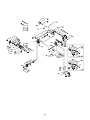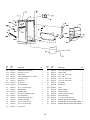
1
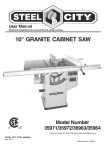
User Manual
Read and understand this manual before using machine.
TABLE SAW
Shown with optional Fence
Model Numbers
35600
35605
®
C
US
STEEL CITY TOOL WORKS
Manual Part No. OR70131
eel City Table
St
w
ne
ur
yo
ng
si
ha
rc
pu
THANK YOU for
tested, and inspected
,
ed
gn
si
de
en
be
s
ha
w
Saw. This table sa
ly used and
er
op
pr
n
he
W
d.
in
m
in
,
with you, the customer
e you with years of
id
ov
pr
ill
w
w
sa
e
bl
ta
maintained, your
by one of the
ed
ck
ba
is
it
hy
w
is
ch
trouble free service, whi
s in the business.
ie
nt
ra
ar
w
ry
ne
hi
ac
m
t
longes
products in the Steel
y
an
m
of
e
on
st
ju
is
w
This table sa
ry and is proof of
ne
hi
ac
m
ng
ki
or
dw
oo
w
City’s family of
satisfaction.
er
om
st
cu
l
ta
to
to
t
en
our commitm
cellence each and
ex
r
fo
ve
ri
st
to
ue
in
nt
co
At Steel City we
customer. For
r
ou
u,
yo
of
n
io
in
op
e
every day and value th
City Tool Works,
l
ee
St
or
w
sa
e
bl
ta
ur
yo
comments about
works.com .
ol
to
ty
ci
el
te
.s
w
w
w
at
te
please visit our web si
2
TABLE OF CONTENTS
INTRODUCTION
SECTION 1
Warranty .................................................................................................................................................4
SECTION 2
Product Specifications ............................................................................................................................7
SECTION 3
Accessories and Attachments ................................................................................................................7
SECTION 4
Definition of Terms ..................................................................................................................................8
SECTION 5
Feature Identification ..............................................................................................................................9
SECTION 6
General Safety......................................................................................................................................10
SECTION 7
Product Safety ......................................................................................................................................12
SECTION 8
Electrical Requirements........................................................................................................................13
SECTION 9
Unpacking & Inventory..........................................................................................................................15
SECTION 10
Assembly ..............................................................................................................................................17
SECTION 11
Adjustments ..........................................................................................................................................22
SECTION 12
Operations ............................................................................................................................................28
SECTION 13
Maintenance .........................................................................................................................................33
SECTION 14
Troubleshooting ....................................................................................................................................34
SECTION 15
Parts List..........................................................................................................................................36-41
INTRODUCTION
This user manual is intended for use by anyone working with this machine. It should be kept available
for immediate reference so that all operations can be performed with maximum efficiency and safety.
Do not attempt to perform maintenance or operate this machine until you have read and understand the
information contained in this manual.
The drawings, illustrations, photographs, and specifications in this user manual represent your machine
at time of print. However, changes may be made to your machine or this manual at any time with no
obligation to Steel City Tool Works.
3
WARRANTY
STEEL CITY TOOL WORKS
5 YEAR LIMITED WARRANTY
Steel City Tool Works, LLC (“SCTW”) warrants all “STEEL CITY TOOL WORKS” machinery to be
free of defects in workmanship and materials for a period of 5 years from the date of the original retail
purchase by the original owner. SCTW will repair or replace, at its expense and at its option, any
SCTW machine, machine part, or machine accessory which in normal use has proven to be defective,
provided that the customer returns the product, shipping prepaid, to an authorized service center with
proof of purchase and provides SCTW with a reasonable opportunity to verify the alleged defect by
inspection. This warranty does not apply to defects due directly or indirectly to misuse, abuse,
negligence, accidents, or lack of maintenance, or to repairs or alterations made or specifically authorized
by anyone other than SCTW. Normal wear components are also excluded under this coverage. Every
effort has been made to ensure that all SCTW machinery meets the highest quality and durability
standards. We reserve the right to change specifications at any time due to our commitment to
continuous improvement of the quality of our products.
EXCEPT AS SET FORTH ABOVE, SCTW MAKES NO EXPRESS OR IMPLIED REPRESENTATIONS OR WARRANTIES WITH RESPECT TO ITS MACHINERY, OR ITS CONDITION,
MERCHANTABILITY, OR FITNESS FOR ANY PARTICULAR PURPOSE OR USE. SCTW
FURNISHES THE ABOVE WARRANTIES IN LIEU OF ALL OTHER WARRANTIES, EXPRESS
OR IMPLIED, INCLUDING THE WARRANTIES OF MERCHANTABILITY AND FITNESS FOR A
PARTICULAR PURPOSE, WHICH ARE HEREBY SPECIFICALLY DISCLAIMED.
SCTW SHALL NOT BE LIABLE FOR ANY (A) SPECIAL, INDIRECT, INCIDENTAL, PUNITIVE
OR CONSEQUENTIAL DAMAGES, INCLUDING WITHOUT LIMITATION LOSS OF PROFITS,
ARISING FROM OR RELATED TO THIS WARRANTY, THE BREACH OF ANY AGREEMENT OR
WARRANTY, OR THE OPERATION OR USE OF ITS MACHINERY, INCLUDING WITHOUT
LIMITATION DAMAGES ARISING FROM DAMAGE TO FIXTURES, TOOLS, EQUIPMENT,
PARTS OR MATERIALS, DIRECT OR INDIRECT LOSS CAUSED BY ANY OTHER PARTY, LOSS
OF REVENUE OR PROFITS, FINANCING OR INTEREST CHARGES, AND CLAIMS BY ANY
THIRD PERSON, WHETHER OR NOT NOTICE OF SUCH POSSIBLE DAMAGES HAS BEEN
GIVEN TO SCTW; (B) DAMAGES OF ANY KIND FOR ANY DELAY BY OR FAILURE OF SCTW
TO PERFORM ITS OBLIGATIONS UNDER THIS AGREEMENT; OR (C) CLAIMS MADE A
SUBJECT OF A LEGAL PROCEEDING AGAINST SCTW MORE THAN ONE (1) YEAR AFTER
SUCH CAUSE OF ACTION FIRST AROSE.
The validity, construction and performance of this Warranty and any sale of machinery by SCTW shall
be governed by the laws of the Commonwealth of Pennsylvania, without regard to conflicts of laws provisions of any jurisdiction. Any action related in any way to any alleged or actual offer, acceptance or
sale by SCTW, or any claim related to the performance of any agreement including without limitation
this Warranty, shall take place in the federal or state courts in Allegheny County, Pennsylvania.
STEEL CITY TOOL WORKS
4
WARRANTY CARD
Name ________________________________________________
Street _______________________________________________
Apt. No. ______________________________________________
City _________________________ State ______ Zip __________
Phone Number_________________________________________
E-Mail ________________________________________________
The following information is given on a voluntary basis
and is strictly confidential.
Where did you purchase your STEEL CITY machine?
Store: ____________________________________________
City:______________________________________________
2.
How did you first learn of Steel City Tool Works?
___ Advertisement
___ Mail Order Catalog
___ Web Site
___ Friend
___ Local Store
! CUT HERE
3.
4.
5.
6.
7.
do you subscribe to?
___ American How-To
___ Family Handyman
___ Fine Woodworking
___ Journal of Light Construction
___ Popular Mechanics
___ Popular Woodworking
___ Old House Journal
___ Popular Science
___ Today’s Homeowner
___ WOOD
___ WOODEN Boat
___ Woodsmith
___ Woodcraft
___ Woodshop News
___ Woodwork
___ Woodworker
___ Workbench
___ Woodworker’s Journal
Other_________________
What is your age group?
___ 20 to 29 years
___ 40 to 49 years
___ 60 to 69 years
How many Steel City machines do you own? _____________
12. Which portable / hand held power tools do you own?
Check all that apply.
___ Belt Sander
___ Biscuit Jointer
___ Dust Collector
___ Circular Saw
___ Detail Sander
___ Drill / Driver
___ Miter Saw
___ Palm Sander
___ Orbital Sander
___ Portable Thickness Planer
___ Saber Saw
___ Router
___ Reciprocating Saw
Other_______________________
13. What machines / accessories would you like to see added to the
STEEL CITY line?
____________________________________________________
____________________________________________________
Which of the following woodworking / remodeling shows do
you watch?
___ Backyard America ___ The American Woodworker
___ Home Time
___ The New Yankee Workshop
___ This Old House
___ Woodwright’s Shop
Other__________________________________________
What is your annual household
___ $20,000 to $29,999
___ $40,000 to $49,999
___ $60,000 to $69,999
___ $80,000 to $89,999
9.
11. Which benchtop tools do you own? Check all that apply.
___ Belt Sander
___ Belt / Disc Sander
___ Drill Press
___ Band Saw
___ Grinder
___ Mini Jointer
___ Mini Lathe
___ Scroll Saw
___ Spindle / Belt Sander
Other______________________
Other_______________________
Which of the following magazines
___ American Woodworker
––– Cabinetmaker
___ Fine Homebuilding
How would you rank your woodworking skills?
___ Simple
___ Intermediate
___ Advance
___ Master Craftsman
10. What stationary woodworking tools do you own?
Check all that apply.
___ Air Compressor
___ Band Saw
___ Drill Press
___ Drum Sander
___ Dust Collection
___ Horizontal Boring Machine
___ Jointer
___ Lathe
___ Mortiser
___ Panel Saw
___ Planer
___ Power Feeder
___ Radial Arm Saw
___ Shaper
___ Spindle Sander
___ Table Saw
___ Vacuum Veneer Press
___ Wide Belt Sander
Other____________________________________________
Product Description:_____________________________________
Model No.: ___________________________________________
Serial No. _____________________________________________
1.
8.
14. What new accessories would you like to see added?
____________________________________________________
____________________________________________________
income?
___ $30,000 to $39,999
___ $50,000 to $59,999
___ 70,000 to $79,999
___ $90,000 +
15. Do you think your purchase represents good value?
___ No
___Yes
16. Would you recommend STEEL CITY products to a friend?
___ No
___ Yes
___ 30 to 39 years
___ 50 to 59 years
___ 70 + years
17. Comments:
____________________________________________________
____________________________________________________
____________________________________________________
____________________________________________________
____________________________________________________
How long have you been a woodworker?
___ 0 to 2 years
___ 2 to 8 years
___ 8 to 20 years
___ over 20 years
5
FOLD ON DOTTED LINE
PLACE
STAMP
HERE
Steel City Tool Works
P.O. Box 10529
Murfreesboro, TN 37129
FOLD ON DOTTED LINE
6
PRODUCT SPECIFICATIONS
Model Number 35600
Model Number 35605
Motor type
Induction
Induction
HP
1.75
3
Amps
15 / 7.5
13
Volts
115 / 230
230
Hertz
60
60
RPM
3450
3450
Blade Tilt
Left
Left
Blade Drive
Poly-V Belt
Poly-V Belt
Blade Diameter
10-in
10-in
Blade Arbor
5/8-in
5/8-in
Number of Teeth
40
40
Blade Speed
3450
3450
Max Depth of cut at 90°
3-3/8-in
3-3/8-in
Max Depth of cut at 45°
2-1/4-in
2-1/4-in
Table in front of blade
at max depth of cut
12-1/2-in
12-1/2-in
Max Dado width
13/16-in
13/16-in
Max Dado blade diameter
8-in
8-in
Left and right table wing
12-in cast iron
12-in cast iron
Footprint
20” x 22”
20” X 22”
Length
44”
44”
Width
32”
32”
Height
40”
40”
Net Weight
320lbs
334lbs
Length
30-1/2-in
30-1/2-in
Width
29-1/2-in
29-1/2-in
Height
43-in
43-in
Gross Weight
370 lbs
385 lbs
Product Dimensions
Shipping Dimensions
ACCESSORIES AND ATTACHMENTS
There are a variety of accessories available for your Steel City Product. For more information on
any accessories associated with this and other machines, please contact your nearest Steel City
distributor, or visit our website at: www.steelcitytoolworks.com.
7
DEFINITION OF TERMS
Anti-Kickback Fingers – A safety device attached to
the blade guard and splitter assembly designed to
minimize the chance of a workpiece being thrown back
during a cutting operation.
Heeling – The misalignment of the blade to the miter
slots; when the blade is not parallel to the miter slots.
Kerf – The material removed by the blade in the workpiece during any cutting operation.
Arbor – The shaft on which the blade or accessory
cutting-tool is mounted.
Kickback – When the workpiece is thrown back toward
the operator at a high rate of speed during a cutting
operation.
Bevel Cut – The operation of making any cut with the
blade set on a degree other than 90 degrees.
Miter Cut – The operation of making a cut using the
miter gauge at any angle other than zero degrees.
Compound Cut – The operation of making both a
bevel and a miter cut at one time.
Push Stick – An accessory device that can be made or
purchased to help push the workpiece through the
blade. A push stick is used to keep the operator’s
hands away from the blade when ripping a narrow
workpiece.
Crosscut – The operation of making a cut across the
grain or width of a workpiece.
Dado – A non-through cut that produces a square
notch. A dado is typically from 1/8-in. to 13/16-in. wide.
A dado requires a special set of blades, not included
with this table saw.
Rabbet – A square notch in the edge of the workpiece.
Rip Cut – The operation of making a cut with the grain
of the workpiece.
Featherboard – An accessory device that can be made
or purchased to help guide or hold down a workpiece
during cutting operations.
Saw Blade Path – The area that is directly in line with
the blade, including area over, under, behind and in
front of it.
Freehand – A very dangerous operation of making a
cut without using the fence or miter gauge in a cutting
operation. FREEHAND CUTS MUST NEVER BE
PERFORMED ON A TABLE SAW.
Set of the Saw Blade – The distance that the tips of
the saw blade are angled outwards from the thickness
of the blade. The set of the saw blade teeth allows for
the blade body to pass safely through all cuts.
Gum, Pitch or Resin – A sticky, sap based residue that
comes from wood products.
Table/Work Area – The total surface of the top of the
table saw on which the workpiece rests while set-up or
cutting operations are being performed.
8
FEATURE IDENTIFICATION
A
B
F
E
H
C
G
D
A)
Miter Gauge
B)
Blade Guard Assembly
C)
Motor Cover
D)
Bevel Scale
E)
Raise/Lower Handwheel
F)
Bevel Adjustment Handwheel
G) Fence Hooks
H)
On/Off Switch
(shown with an optional fence)
9
GENERAL SAFETY
!
!
WARNING
WARNING
TO AVOID serious injury and damage to the machine,
read and follow all Safety and Operating Instructions
before assembling and operating this machine.
This manual is not totally comprehensive. It does not
and can not convey every possible safety and operational problem which may arise while using this
machine. The manual will cover many of the basic and
specific safety procedures needed in an industrial environment.
Exposure to the dust created by power sanding, sawing, grinding, drilling and other construction activities
may cause serious and permanent respiratory or
other injury, including silicosis (a serious lung disease), cancer, and death. Avoid breathing the dust,
and avoid prolonged contact with dust. The dust
may contain chemicals known to the State of
California to cause cancer, birth defects or other
reproductive harm.
All federal and state laws and any regulations having
jurisdiction covering the safety requirements for use of
this machine take precedence over the statements in
this manual. Users of this machine must adhere to all
such regulations.
Some examples of these chemicals are:
• Lead from lead-based paints.
• Crystalline silica from bricks, cement and other
masonry products.
• Arsenic and chromium from chemically-treated
lumber.
Below is a list of symbols that are used to attract your
attention to possible dangerous conditions.
!
This is the safety alert symbol. It is used to alert you to
potential personal injury hazards. Obey all safety messages that follow this symbol to avoid possible injury or
death.
!
Always operate tool in well ventilated area and provide for proper dust removal. Use a dust collection
system along with an air filtration system whenever
possible. Always use properly fitting NIOSH/OSHA
approved respiratory protection appropriate for the
dust exposure, and wash exposed areas with soap
and water.
DANGER
Indicates an imminently hazardous situation which, if
not avoided, WILL result in death or serious injury.
!
1. To avoid serious injury and damage to the machine,
read the entire User Manual before assembly and
operation of this machine.
WARNING
Indicates a potentially hazardous situation which, if not
avoided, COULD result in death or serious injury.
!
CAUTION
!
WARNING
Indicates a potentially hazardous situation, if not avoided, MAY result in minor or moderate injury. It may also
be used to alert against unsafe practices.
CAUTION
2. ALWAYS wear eye protection. Any machine can
throw debris into the eyes during operations,
which could cause severe and permanent eye
damage. Everyday eyeglasses are NOT safety
glasses. ALWAYS wear Safety Goggles (that
comply with ANSI standard Z87.1) when operating power tools.
CAUTION used without the safety alert symbol indicates a potentially hazardous situation which, if not
avoided, may result in property damage.
NOTICE
This symbol is used to alert the user to useful information about proper operation of the machine.
10
!
11. DO NOT FORCE the machine to perform an operation for which it was not designed. It will do a safer
and higher quality job by only performing operations
for which the machine was intended.
WARNING
12. DO NOT stand on a machine. Serious injury could
result if it tips over or you accidentally contact any
moving part.
3. ALWAYS wear hearing protection. Plain cotton is
not an acceptable protective device. Hearing
equipment should comply with ANSI S3.19
Standards.
!
13. DO NOT store anything above or near the machine.
14. DO NOT operate any machine or tool if under the
influence of drugs, alcohol, or medication.
WARNING
15. EACH AND EVERY time, check for damaged parts
prior to using any machine. Carefully check all
guards to see that they operate properly, are not
damaged, and perform their intended functions.
Check for alignment, binding or breakage of all
moving parts. Any guard or other part that is damaged should be immediately repaired or replaced.
4. ALWAYS wear a NIOSH/OSHA approved dust
mask to prevent inhaling dangerous dust or airborne particles.
16. Ground all machines. If any machine is supplied
with a 3-prong plug, it must be plugged into a 3contact electrical receptacle. The third prong is
used to ground the tool and provide protection
against accidental electric shock. DO NOT remove
the third prong.
5. ALWAYS keep the work area clean, well lit, and
organized. DO NOT work in an area that has slippery floor surfaces from debris, grease, and wax.
6. ALWAYS unplug the machine from the electrical
receptacle when making adjustments, changing
parts or performing any maintenance.
17. Keep visitors and children away from any machine.
DO NOT permit people to be in the immediate work
area, especially when the machine is operating.
7. AVOID ACCIDENTAL STARTING. Make sure that
the power switch is in the “OFF” position before
plugging in the power cord to the electrical
receptacle.
!
18. KEEP protective guards in place and in working
order.
19. MAINTAIN your balance. DO NOT extend yourself
over the tool. Wear oil resistant rubber soled shoes.
Keep floor clear of debris, grease, and wax.
WARNING
20. MAINTAIN all machines with care. ALWAYS KEEP
machine clean and in good working order. KEEP all
blades and tool bits sharp.
8. AVOID a dangerous working environment. DO
NOT use electrical tools in a damp environment
or expose them to rain or moisture.
!
21. NEVER leave a machine running, unattended. Turn
the power switch to the OFF position. DO NOT
leave the machine until it has come to a complete
stop.
22. REMOVE ALL MAINTENANCE TOOLS from the
immediate area prior to turning the machine ON.
WARNING
23. SECURE all work. When it is possible, use clamps
or jigs to secure the workpiece. This is safer than
attempting to hold the workpiece with your hands.
9. CHILDPROOF THE WORKSHOP AREA by
removing switch keys, unplugging tools from the
electrical receptacles, and using padlocks.
24. STAY ALERT, watch what you are doing, and use
common sense when operating any machine. DO
NOT operate any machine tool while tired or under
the influence of drugs, alcohol, or medication. A
moment of inattention while operating power tools
may result in serious personal injury.
10. DO NOT use electrical tools in the presence of
flammable liquids or gasses.
11
25. USE ONLY recommended accessories. Use of
incorrect or improper accessories could cause serious injury to the operator and cause damage to the
machine. If in doubt, DO NOT use it.
3. Prevent electrical shock. Follow all electrical and
safety codes, including the National Electrical Code
(NEC) and the Occupational Safety and Health
Regulations (OSHA). All electrical connections and
wiring should be made by qualified personnel only.
26. THE USE of extension cords is not recommended
for 230V equipment. It is better to arrange the
placement of your equipment and the installed
wiring to eliminate the need for an extension cord.
If an extension cord is necessary, refer to the chart
in the Grounding Instructions section to determine
the minimum gauge for the extension cord. The
extension cord must also contain a ground wire and
plug pin.
!
WARNING
4. TO REDUCE the risk of electrical shock. DO
NOT use this machine outdoors. DO NOT
expose to rain or moisture. Store indoors in a
dry area.
27. Wear proper clothing, DO NOT wear loose clothing,
gloves, neckties, or jewelry. These items can get
caught in the machine during operations and pull
the operator into the moving parts. Users must
wear a protective cover on their hair, if the hair is
long, to prevent it from contacting any moving parts.
5. STOP using this machine, if at any time you experience difficulties in performing any operation.
Contact your supervisor, instructor or machine service center immediately.
28. SAVE these instructions and refer to them frequently and use them to instruct other users.
6. Safety decals are on this machine to warn and
direct you to how to protect yourself or visitors from
personal injury. These decals MUST be maintained
so that they are legible. REPLACE decals that are
not legible.
29. Information regarding the safe and proper operation
of this tool is also available from the following
sources:
Power Tool Institute
1300 Summer Avenue
Cleveland, OH 44115-2851
www.powertoolinstitute.org
7. DO NOT leave the unit plugged into the electrical
outlet. Unplug the unit from the outlet when not in
use and before servicing, performing maintenance
tasks, or cleaning.
National Safety Council
1121 Spring Lake Drive
Itasca, IL 60143-3201
8. ALWAYS turn the power switch “OFF” before
unplugging the table saw.
American National Standards Institute
25 West 43rd Street, 4th floor
New York, NY 10036
www.ansi.org
!
ANSI 01.1 Safety Requirements for
Woodworking Machines, and the U.S. Department
of Labor regulations
www.osha.gov
WARNING
9. DO NOT handle the plug or table saw with
wet hands.
10. USE accessories only recommended by Steel City.
PRODUCT SAFETY
11. DO NOT pull the table saw by the power cord.
NEVER allow the power cord to come in contact
with sharp edges, hot surfaces, oil or grease.
1. Serious personal injury may occur if normal safety
precautions are overlooked or ignored. Accidents
are frequently caused by lack of familiarity or failure
to pay attention. Obtain advice from supervisor,
instructor, or another qualified individual who is
familiar with this machine and its operations.
12. DO NOT unplug the table saw by pulling on the
power cord. ALWAYS grasp the plug, not the cord.
13. REPLACE a damaged cord immediately. DO NOT
use a damaged cord or plug. If the table saw is not
operating properly, or has been damaged, left outdoors or has been in contact with water.
2. Every work area is different. Always consider safety first, as it applies to your work area. Use this
machine with respect and caution. Failure to do so
could result in serious personal injury and damage
to the machine.
14. DO NOT use the table saw as a toy. DO NOT use
near or around children.
12
15. ENSURE that the machine sits firmly on the floor
before using. If the machine wobbles or is unstable,
correct the problem by using shims or blocks prior
to operation.
22. DO NOT use the rip fence as a guide when crosscutting.
23. BE MINDFUL of flaws in the wood. Cutting a
warped or twisted board along the rip fence can get
pinched between the fence and the blade, causing
a kickback.
16. KEEP saw blade sharp and clean. Failure to do so
greatly increases friction, decreases cut quality, and
increases the possibility of a kickback.
24. ALWAYS remove cut off pieces and scraps from
the table before starting the saw.
17. MAKE CERTAIN the saw blade is parallel with the
miter slots and with the rip fence. A blade that is
not aligned parallel can cause the workpiece to be
pinched between the blade and the fence causing
burning or kickbacks.
25. NEVER start the machine with the workpiece
against the blade.
26. NEVER perform freehand operations. Use either
the fence or miter gauge to position and guide the
workpiece through the blade.
18. ALWAYS use blade guard on all through cuts.
This will help prevent the cut from closing on the
back of the saw blade. The blade guard also has
anti-kickback fingers which minimize the chance
of a workiece being thrown back during a cutting
operation.
27. ALWAYS use a pushstick for ripping narrow workpieces.
28. NEVER have any part of your body in line with the
path of the saw blade. If a kickback occurs with
you directly in front of the blade, a serious injury
can occur.
19. ALWAYS push the workpiece past the blade. DO
NOT release a workpiece until it is past the blade
and removed from the saw.
29. NEVER attempt to free a stalled blade without first
turning the machine off and disconnecting the saw
from the power source.
20. DO NOT execute a cut when you do not have
complete control of the situation.
21. DO NOT cut a workpiece that is too large for you to
handle.
ELECTRICAL REQUIREMENTS
!
prewired for 115 volt operation. If you decide to convert
the saw to 230V, you will have to replace the 115 volt
plug on the switch with a UL/CSA Listed plug, suitable
for 230 volts. The table saw with a 230 volt plug should
only be connected to an outlet having the same configuration as the plug. No adapter is available or should
be used with the 230 volt plug. Once the modification
has been made to the plug of the switch, be sure to follow the instructions under CHANGING MOTOR VOLTAGE for changing the motor voltage from 115 volt to
230 volt in the ADJUSTMENTS section of this manual.
WARNING
To reduce the risk of electric shock, follow all electrical and safety codes, including the National Electric
Code (NEC) and the Occupational Safety and Health
Regulations (OSHA). All electrical connections and
wiring should be made by qualified personnel only.
This manual is written for two specific models,
Model No 35600 and Model No 35605. Please follow
the specific requirements for your model saw.
MODEL NO 35605
The switch provided with your saw is a magnetic switch
designed for 230 volt single phase usage only. The
switch has a plug that is designed to plug into a 230
volt outlet. There are many different configurations for
230 volt outlets, so it is conceivable that the configuration of the plug may not match the configuration of your
existing outlet. If this is the case, you will have to
replace the plug with a UL/CSA approved plug that
matches the configuration of your 230V outlet.
MODEL NO 35600
The switch provided with your saw is a dual voltage
capable switch, meaning it is designed to function at
either 115 or 230 volts. The switch and saw comes
13
GROUNDING INSTRUCTIONS
!
EXTENSION CORDS
WARNING
!
WARNING
This machine MUST BE GROUNDED while in use to
protect the operator from electric shock.
To reduce the risk of fire or electrical shock, use the
proper gauge of extension cord. When using an
extension cord, be sure to use one heavy enough to
carry the current your machine will draw.
In the event of a malfunction or breakdown, GROUNDING provides the path of least resistance for electric
current and reduces the risk of electric shock. The plug
MUST be plugged into a matching electrical receptacle
that is properly installed and grounded in accordance
with ALL local codes and ordinances.
The smaller the gauge-number, the larger the diameter
of the extension cord is. If in doubt of the proper size of
an extension cord, use a shorter and thicker cord. An
undersized cord will cause a drop in line voltage resulting in a loss of power and overheating.
If a plug is provided with your machine DO NOT modify
the plug. If it will not fit your electrical receptacle, have
a qualified electrician install the proper connections to
meet all electrical codes local and state. All connections
must also adhere to all of OSHA mandates.
!
IMPROPER ELECTRICAL CONNECTION of the equipment-grounding conductor can result in risk of electric
shock. The conductor with the green insulation (with or
without yellow stripes) is the equipment-grounding conductor. DO NOT connect the equipment-grounding conductor to a live terminal if repair or replacement of the
electric cord or plug is necessary.
CAUTION
USE ONLY a 3-wire extension cord that has a 3-prong
grounding plug and a 3-pole receptacle that accepts the
machine’s plug.
If you are using an extension cord outdoors, be sure it
is marked with the suffix “W-A” (“W” in Canada) to indicate that it is acceptable for outdoor use.
Check with a qualified electrician or service personnel if
you do not completely understand the grounding
instructions, or if you are not sure the tool is properly
grounded.
Make certain the extension cord is properly sized, and
in good electrical condition. Always replace a worn or
damaged extension cord immediately or have it
repaired by a qualified person before using it.
PLUGS/RECEPTACLES
Protect your extension cords from sharp objects, excessive heat, and damp or wet areas.
!
WARNING
MINIMUM RECOMMENDED GAUGE FOR EXTENSION CORDS (AWG)
115 VOLT OPERATION ONLY
• Electrocution or fire could result if this machine is
not grounded properly or if the electrical configuration does not comply with local and state electrical
codes.
0 to 6 Amps
6 to 10 Amps
10 to 12 Amps
12 to 15 Amps
• MAKE CERTAIN the machine is disconnected
from power source before starting any electrical
work.
50’ LONG
100’ LONG
18 AWG
18 AWG
16 AWG
14 AWG
16 AWG
16 AWG
16 AWG
12 AWG
16 AWG
14 AWG
14 AWG
Not
recommended
MINIMUM RECOMMENDED GAUGE FOR EXTENSION CORDS (AWG)
• MAKE SURE the circuit breaker does not exceed
the rating of the plug and receptacle.
230 VOLT OPERATION ONLY
The motor supplied with your machine is either a
115/230 dual voltage motor (Model 35600) or a dedicated 230 volt, single phase motor (Model 35605). Never
connect the green or ground wire to a live terminal.
The machine should only be connected to an outlet
having the same configuration as the plug.
25’ LONG
0 to 6 Amps
6 to 10 Amps
10 to 12 Amps
12 to 15 Amps
14
25’ LONG
50’ LONG
100’ LONG
18 AWG
18 AWG
16 AWG
14 AWG
18 AWG
18 AWG
16 AWG
12 AWG
16 AWG
14 AWG
14 AWG
Not
recommended
UNPACKING & INVENTORY
!
can be removed by spraying WD-40 on them and wiping it off with a soft cloth. This may need redone several times before all of the protective coatings are
removed completely.
WARNING
After cleaning, apply a good quality paste wax to any
unpainted surfaces. Make sure to buff out the wax
before assembly.
• The machine is heavy, two people are required to
unpack and lift.
Compare the items to inventory figures; verify that all
items are accounted for before discarding the shipping
box.
• Use a safety strap to avoid tip over when lifting
machine.
Check shipping carton and machine for damage before
unpackaging. Carefully remove packaging materials,
parts and machine from shipping carton. Always check
for and remove protective shipping materials around
motors and moving parts. Lay out all parts on a clean
work surface.
!
WARNING
If any parts are missing, do not attempt to plug in the
power cord and turn “ON” the machine. The machine
should only be turned “ON” after all the parts have been
obtained and installed correctly. For missing parts,
contact Steel City at 1-877-SC4-TOOL.
Remove any protective materials and coatings from all
of the parts and the table saw. The protective coatings
I
A
B
H
G
C
F
D
E
A) Dust Port
E) Handwheel Lock Knob (2)
I)
B) Blade Guard and Splitter Assembly
F) Handwheel Assembly (2)
C) On/Off Switch
G) Splitter Mounting Rod
J) Fence Hooks (2)
(not shown)
D) Miter Gauge
H) Splitter Bracket Assembly
15
Blade Wrenches
K) Wrench Hook (not shown)
L) M8 x 1.25 x
30mm Hex Head
Screw (8)
L
M) M8 Flat Washer
(8)
N) M8 Lockwasher
(8)
O) 1/4-20 x 1/2”
Round Head
Screw (10)
M
N
O
P
P) Cast Iron Wings
16
ASSEMBLY
!
POLY-V BELT ASSEMBLY
WARNING
WARNING
• The table saw is a heavy machine; two people may
be required for certain assembly operations.
!
• DO NOT assemble the table saw until you are sure
the tool is unplugged.
MAKE CERTAIN THAT THE SAW IS DISCONNECTED FROM THE POWER SOURCE.
• DO NOT assemble the table saw until you are sure
the power switch is in the “OFF” position.
Fig. 2
• For your own safety, DO NOT connect the machine to
the power source until the machine is completely
assembled and you read and understand this entire
User Manual.
B
INSTALLATION AND LEVELING
A
Final location for the saw must be level, dry, well lighted, and have enough room to allow movement around
the saw with long pieces of wood stock.
Level the saw front to back and side to side, using a
carpenter’s level placed on the table. Use shims under
the corners, if necessary, but make sure the saw is
stable before being placed into service.
C
DUST PORT ASSEMBLY
!
WARNING
1. Make sure all packaging material has been
removed from inside the cabinet.
MAKE CERTAIN THAT THE SAW IS DISCONNECTED FROM THE POWER SOURCE.
2. Open the motor cover and place the motor Poly-V
belt (A) over the blade pulley (B). SEE FIG. 2.
Fig. 1
3. Carefully lift the motor (C) and place the belt under
the motor pulley (not shown). Make sure all the
v-notches in the belt are mated with the v-notches
of the blade pulley and motor pulley.
A
4. Carefully let the motor down and close motor cover.
EXTENSION WING ASSEMBLY
!
WARNING
MAKE CERTAIN THAT THE SAW IS DISCONNECTED FROM THE POWER SOURCE.
1. CAUTION: The extension wings are heavy; two
people are required to assemble both extension
wings to the table saw.
1. Attach the dust port (A) to the opening in the
bottom rear of the cabinet with four 1/4-20 x 1/2”
round head tap screws. SEE FIG. 1.
17
HANDWHEEL ASSEMBLY
Fig. 3
!
A
WARNING
MAKE CERTAIN THAT THE SAW IS DISCONNECTED FROM THE POWER SOURCE.
Fig. 5
D
B
B
B
C
2. Assemble one of the extension wings (A) to the left
side of the table saw. Align the four holes (B) in the
extension wing with the four holes in the left side of
the saw table. Use four M8 x 30mm hex head
screws, M8 lock washers and M8 flat washers to
attach the wing to the table. Do not completely
tighten hardware at this time. SEE FIG. 3.
A
1. Place one of the handwheels (A) onto the blade
raise/lower shaft (B) located on the front of the
cabinet. Align the groove (C) in the back of the
handwheel with the pin (D). SEE FIG. 5.
Fig. 4
D
E
Fig. 6
E
C
3. Lay a straight edge or level (C) across the saw
table (D) and extension wing (E). Make sure that
the front face of the extension wing is flat to the
front face of the saw table. Adjust the extension
wing so that its top surface is exactly flat to the saw
table and securely tighten hardware. SEE FIG. 4.
2. Thread the locking knob (E) onto the threaded end
of the shaft. SEE FIG. 6.
4. Repeat steps 2 and 3 above to assemble the other
extension wing to the right side of the table saw.
3. Repeat the steps above to assemble the remaining
handwheel and locking knob onto the bevel shaft
located on the side of the cabinet.
18
WRENCH AND FENCE
HOOK ASSEMBLY
!
2. Place the threaded end of the mounting splitter rod
(A) through the hole (B) in the rear of the cabinet.
Place a M12 hex nut (not shown) onto the threaded
end of the mounting splitter rod inside of the cabinet and tighten securely. SEE FIGS. 8 AND 9.
WARNING
Note: Place an 18mm wrench on 12mm hex nut and a
13mm wrench on flats of the splitter rod and tighten.
MAKE CERTAIN THAT THE SAW IS DISCONNECTED FROM THE POWER SOURCE.
Fig. 9
Fig. 7
C
C
A
B
A
1. Assemble both of the fence hooks (A) to the left
side of the cabinet (B) using four 1/4-20 c 1/2”
round head screws, not shown. SEE FIG. 7.
2. Assemble the wrench hook (C) above the fence
hooks using two sheet metal screws, not shown.
3. Place the splitter bracket assembly (C) onto the
mounting splitter rod. SEE FIG. 9.
BLADE GUARD AND
SPLITTER ASSEMBLY
!
Fig. 10
WARNING
MAKE CERTAIN THAT THE SAW IS DISCONNECTED FROM THE POWER SOURCE.
F
D
1. Remove the table insert. Note: Remove the table
insert retaining bolt used to secure the table insert
to the saw table.
E
Fig. 8
G
4. Place the front attachment point (D) of the blade
guard and splitter assembly down into the tool-less
front attachment point (E). Place the rear attachment
slot (F) onto the threads of the splitter bracket knob
(G); securely tighten splitter bracket knob. Note: The
splitter bracket assembly will need to be positioned
to fit the blade guard and splitter assembly on the
mounting splitter rod. SEE FIG. 10.
B
19
Fig. 11
7. Place a square (N) onto the saw table and against
the splitter assembly (O) behind the kickback fingers (P). Make adjustments to the splitter bracket
assembly (Q) so that the splitter is square to the
saw table. Once square, tighten the two hex socket
head screws on the bottom of the splitter bracket
assembly. SEE FIG. 12.
Z
Fig. 13
L
M
I
K
J
5. Remove the hex nut (K) and outer flange (J) from
the blade arbor (I). Note: The arbor has a right
hand thread; to loosen the hex nut turn it counterclockwise.
T
6. Place 10” saw blade (Z) onto blade arbor (I), make
sure the teeth of the blade are pointing down in the
front of the table saw. Place the outer flange (J)
and hex nut (K) onto the blade arbor and snug hex
nut by hand. Place the open-end blade wrench (L)
on the flats of the inner blade flange (not shown)
and the box-end blade wrench (M) onto the hex nut
and securely tighten. Note: The blade arbor has a
right hand thread, to tighten the hex nut turn it
clockwise. SEE FIG. 11.
S
R
Fig. 12
8. Lay a straight edge (R) against the left side of the
saw blade (S). Align the splitter (T) so that it is in a
straight line with the blade and tighten the one hex
socket head screw on top of the splitter bracket
assembly. SEE FIG. 13.
Q
O
9. Replace table insert and tighten table insert retaining bolt removed in step 1.
10. If there is any problem with the front splitter attachment bracket being out-of-square to the saw table
or blade alignment, see “ALIGNING SPLITTER
BRACKET” in the Adjustments section of this
manual.
N
20
CONNECTING SWITCH CORD
TO MOTOR CORD
!
Fig. 13B
C
WARNING
MAKE CERTAIN THAT THE SAW IS DISCONNECTED FROM THE POWER SOURCE.
1. Place the switch cord (A) through hole (B) in front
of cabinet. SEE FIG. 13A.
D
Fig. 13A
2. Open motor cover, insert three prong switch cord
(C) into three hole outlet (D) of the motor cord. SEE
FIG. 13B.
B
3. Pull slack in switch cord into the cabinet.
A
MOUNTING RAILS, FENCE
AND TABLE BOARD
The rails, fence assembly, and table board can now be
mounted to the saw. See Owner’s Manual for Fence
Assembly Instructions which will address the mounting
of these parts.
21
ADJUSTMENTS
RAISING AND
LOWERING THE BLADE
To tilt the blade bevel to 45-degrees, loosen the handwheel lock knob (counterclockwise) and turn the handwheel clockwise. When the saw blade is at 45-degrees
it will come into contact with the adjustable positive stop
which will cause the blade to stop. Tighten the handwheel lock knob (clockwise) until it is securely tightened.
Fig. 16
B
ADJUSTING BLADE BEVEL
POSITIVE STOPS
Fig. 17
A
B
The blade height adjustment handwheel and handwheel
lock knob are located on the front of the cabinet above
the blade bevel scale. To raise the saw blade, loosen
the handwheel lock knob (A) (counterclockwise) and
turn the handwheel (B) clockwise. When the saw blade
is at its desired height, tighten the handwheel lock knob
(clockwise) until it is securely tightened. SEE FIG. 16.
A
1. To adjust blade to a 90-degree blade bevel positive
stop, raise the saw blade (A) to its highest position.
SEE FIG. 17.
To lower the saw blade, loosen the handwheel lock
knob (counterclockwise) and turn the handwheel
counterclockwise. When the saw blade is at its desired
height, tighten the handwheel lock knob (clockwise)
until it is securely tightened.
2. Using a combination square (B) check that the
blade is 90 degrees to the saw table (zero degrees
on bevel scale).
3. If the blade will not tilt to 90 degrees, turn (counterclockwise) the set screw in the left miter slot of the
saw table until the blade can be positioned to 90
degrees.
TILTING THE BLADE
The blade bevel handwheel and handwheel lock knob
are located on the left side of the cabinet. To increase
the saw blade bevel, loosen the handwheel lock knob
(counterclockwise) and turn the handwheel clockwise.
When the saw blade is at its desired degree, tighten the
handwheel lock knob (clockwise) until it is securely
tightened.
4. Once the blade has been tilted to 90 degrees (confirm this using your square), tighten the bevel handwheel lock knob, located on the side of the cabinet.
This will keep the blade from tilting further.
5. Turn the set screw (clockwise) until it comes in
contact with the positive stop.
To return the saw blade bevel to zero degrees, loosen
the handwheel lock knob (counterclockwise) and turn
the handwheel counterclockwise. When the saw blade
is back to zero degrees it will come into contact with the
adjustable positive stop which will cause the blade to
stop. Tighten the handwheel lock knob (clockwise) until
it is securely tightened.
6. Loosen the bevel handwheel lock knob located on
the side of the cabinet, and rotate bevel handwheel
until the blade is at 45 degrees to the saw table.
22
7. If the blade will not tilt to 45 degrees, turn (counterclockwise) the set screw located just to the right of
the right miter slot, until the blade can be positioned
to 45 degrees.
CHECKING BLADE ALIGNMENT
Fig. 18
Blade heel is the misalignment of the blade to the miter
slots. This means when the blade is not parallel to the
miter slots, it is heeling. The blade is set parallel at the
factory and should not need any adjustments. You can
check this by using a dial indicator (not included) or a
combination square (not included). It is recommended
to check the alignment before initial operation as
follows:
C
!
WARNING
MAKE CERTAIN THAT THE SAW IS DISCONNECTED FROM THE POWER SOURCE.
Fig. 20
8. Using a combination square (C), make sure that the
blade is at 45 degrees. SEE FIG. 18.
9. With the blade at 45 degrees, tighten the bevel
handwheel lock knob to keep the blade from further
tilting.
D
10. Turn the set screw clockwise until it comes in
contact with the positive stop.
C
BEVEL ARROW ADJUSTMENT
1. Make certain that the blade is at 90-degrees to
the table surface with a combination square.
B
A
Fig. 19
A
1. Raise the saw blade to its highest point.
2. Place a combination square (A) on the saw table
with one edge (B) of the square against the left
miter slot (C). SEE FIG. 20.
3. Adjust the square so the rule (D) just touches the
saw blade. Make sure the rule is not touching any
of the carbide tips of the saw blade.
4. Lock the rule in this position.
2. Check that the bevel arrow is pointing to the zero
degree mark on the bevel scale located on the
front of the cabinet. SEE FIG. 19.
3. To adjust arrow, loosen the Philips head screw (A),
and reposition the bevel arrow and tighten screw.
23
Fig. 21
Fig. 22
E
A
B
1. To align the blade parallel to the miter slot, first
loosen two hex head screws (A) under the left side
of the table saw. This is the same side as the bevel
handwheel (B). SEE FIG. 22.
6. Rotate the saw blade back so that you take the
measurement from the same spot on the saw
blade. SEE FIG. 21.
Fig. 23
7. Take a reading at the rear of the blade (E) with the
combination square. If there is a difference of more
than .010 between the rule and the blade, then an
adjustment will have to be made.
8. If an adjustment is necessary, see “ADJUSTING
BLADE ALIGNMENT.”
C
C
ADJUSTING BLADE ALIGNMENT
!
WARNING
Blade alignment is factory set and should not need
adjustment. All saw blades have some runout.
Therefore, readjusting the blade alignment should only
be attempted if it becomes necessary (see checking
blade alignment).
!
2. Open motor cover located on the right side of the
table saw. Loosen two hex head screws (C) located
directly above the opening. SEE FIG. 23.
3. The saw table is now loose and can be repositioned until the blade is parallel to the miter slot.
Repeat steps in “CHECKING BLADE ALIGNMENT.”
WARNING
MAKE CERTAIN THAT THE SAW IS DISCONNECTED FROM THE POWER SOURCE.
4. When blade is parallel to miter slot, tighten all four
hex head screws.
5. Recheck blade alignment.
6. Tilt the blade to 45 degrees, and rotate the saw
blade by hand. Make sure the blade does not
contact the table insert.
24
TABLE INSERT ADJUSTMENT
CHANGING MOTOR VOLTAGE
This section only applies to Model 35600
with the 1-3/4HP Motor. The 35605 Model
with the 3HP motor will only run at 230V.
WARNING
!
MAKE CERTAIN THAT THE SAW IS DISCONNECTED FROM THE POWER SOURCE.
!
Fig. 24
WARNING
MAKE CERTAIN THAT THE SAW IS DISCONNECTED FROM THE POWER SOURCE. Have a certified
electrician make all electrical connections. All
local and state codes must be maintained.
D
D
The motor supplied with the table saw is a dual voltage
115/230-volt, single phase motor. The motor is wired
from the factory for 115-volt operation. To change to
230-volt operation for your table saw, proceed with the
following instructions. It is also necessary to replace
the 115 volt plug, supplied with the table saw, with a
UL/CSA Listed plug (not included) suitable for 230 volts
and the rated current of the motor. The table saw with a
230 volt plug should only be connected to an outlet
having the same configuration as the plug. No adapter
is available or should be used with the 230 volt plug.
A
Fig. 25
B
E
A
C
B
D
1. Make sure the switch is “OFF” and disconnect
power cord from power source.
1. The table insert (A) must always be level with the
saw table (B). To adjust the table insert, loosen
and remove table insert retaining bolt (C).
SEE FIG. 24.
2. Open motor cover and verify on the motor tag that
motor is dual voltage.
3. If motor tag states that it is dual voltage remove
junction box cover (A) on motor (B). SEE FIG. 25.
2. Place a straight edge across the front and rear of
the table insert. Check that the insert is perfectly
level with the saw table.
4. Using wiring diagram on inside of junction box
cover, reconnect motor leads for 230-volt operation.
3. To level the table insert, turn the one or more
adjusting set screws (D) as needed and recheck.
5. Replace junction box cover and close motor cover.
6. Replace the 115-volt plug with a plug rated for 230volt operation.
4. Once the insert is level, secure the insert with the
retaining bolt removed in step 1.
5. The table insert is equipped with a finger hole (E)
for easy removal.
7. The ON/OFF switch is 4-pole and does not need
modified.
25
CHANGING THE SAW BLADE
!
ALIGNING SPLITTER BRACKET
WARNING
!
• Turn the power switch “OFF” and unplug the
power cord from its power source when changing the saw blade.
WARNING
MAKE CERTAIN THAT THE SAW IS DISCONNECTED FROM THE POWER SOURCE.
• USE ONLY 10-in diameter blades with 5/8-inch
arbor holes, rated at or higher than 3800 R.P.M.
Fig. 27
Fig. 26
A
B
A
B
E
C
D
1. To adjust front splitter bracket (A), loosen the two
hex socket head cap screws (B). SEE FIG. 27.
1. Remove blade guard and splitter.
Fig. 28
2. Remove the table insert retaining bolt and remove
the table insert.
E
3. Unlock the raise/lower handwheel lock and raise
saw blade to maximum height.
D
4. Two wrenches are supplied with the table saw.
Place one open-end wrench (A) on the flat of the
saw arbor to keep it from turning. Place the closedend wrench (B) on the arbor nut (C). Turn the arbor
nut wrench toward the front of saw to loosen it.
Remove arbor nut, blade flange (D) and saw blade
(E). SEE FIG. 26.
5. Assemble the new saw blade; make certain the
teeth point down at the front of the saw table and
assemble the blade flange and arbor nut. Using
both blade wrenches as previously mentioned,
tighten arbor nut in the opposite direction from
which it was loosened.
C
2. Place a straight edge (C) along the side of blade
(D) and adjust the front splitter bracket to align the
splitter (E) with the blade. SEE FIG. 28.
6. Replace table insert and tighten the table insert
retaining bolt.
3. Once splitter bracket is aligned, retighten hex
socket head cap screw from STEP 1.
7. Replace blade guard and splitter
26
MITER GAUGE ADJUSTMENT
!
ADJUSTING POSITIVE STOPS
Fig. 30
WARNING
MAKE CERTAIN THAT THE SAW IS DISCONNECTED FROM THE POWER SOURCE.
E
D
Fig. 29
B
A
C
1. To adjust 0-degree positive stops, loosen knob (B),
pull out on plunger (C) and turn miter gauge over.
2. Loosen the lock nut (D) 3 or 4 turns. SEE FIG. 30.
3. Place a square against the guide bar and front of
the miter gauge body. Square the miter gauge
body to the guide bar and tighten knob.
1. The miter gauge has adjustable positive stops at
0-degree and plus or minus 45-degrees or it can be
manually set at any angle between plus or minus
60-degrees.
4. Push in plunger and make adjustments to stop
screw (E) so that it touches the plunger and tighten
lock nut.
2. To rotate miter gauge body (A), loosen knob (B)
and pull out plunger (C) and rotate miter gauge
body to desired angle and tighten knob.
SEE FIG. 29.
5. Recheck the positive stop angle to the saw blade.
Insert the guide bar into the miter slot and slide the
miter gauge up to the saw blade.
3. To rotate to the next positive stop, pull plunger (C)
out, rotate miter gauge body then push plunger
back in and continue rotating miter gauge body until
it stops against next positive stop.
6. To check, place a square against the saw blade
and miter gauge body. If any more adjustments are
need repeat steps above.
7. To set both 45-degree positive stops, repeat steps
1 thru 6 above.
27
OPERATIONS
!
1. The ON/OFF switch is located under the front rail
on the table saw.
CAUTION
• A separate electrical circuit should be used for your
table saw. The circuit should not be less than #14
AWG wire and should be protected with a 15-amp
time lag fuse.
2. To turn the table saw on, press the green “START”
button (A) in one-half inch. Note: There is a safety
feature on the switch to insure that the switch must
be completely pressed before the saw will START.
SEE FIG. A.
• Have a qualified electrician repair or replace damaged
or worn cord immediately.
3. To turn the table saw off, press the large red “OFF”
paddle (B) or lift the paddle and press directly on
the red “OFF” button.
• Before connecting the motor to the power line, make
certain the switch is in the “OFF” position and be sure
that the electric current is of the same characteristics
as the motor nameplate. All line connections should
make good contact.
4. When the table saw is not in use, the “ON” button
should be locked so that it cannot be started.
5. Using a padlock (not provided), it is possible to lock
the switch to prevent unauthorized use. Lift the red
“OFF” paddle and place a padlock through the
holes (C) in the side of the “ON” button and then
lock the padlock. Make sure keys have been
removed from padlock and placed where no
children can get them. SEE FIG. A.
• Running on low voltage or long extension cords will
damage the motor.
!
WARNING
• DO NOT expose the table saw to rain or operate the
in damp locations.
6. To use the table saw, unlock and remove the
padlock from the “ON” button.
• MAKE SURE all parts have been assembled correctly and are in working order.
• KEEP table surface clear of tools and debris before
starting table saw.
THERMAL-OVERLOAD
PROTECTION
STARTING AND
STOPPING THE SAW
!
WARNING
• Turn the power switch “OFF” and unplug the power
cord from its power source prior to doing or performing any maintenance.
Fig. A
• Make certain that the “OFF” button has been depressed before pushing the thermal-overload reset
button.
C
The motor supplied with your table saw has a resettable
thermal-overload relay located on the side of the switch.
If the motor shuts off during an operation (cutting a
workpiece too fast or using a dull blade, using the saw
beyond its capacity, or low voltage) press the “OFF”
button and let the motor cool three to five minutes.
Push the reset thermal-overload button on the side of
the ON/OFF switch assembly. Make certain that the
saw blade and work area has been cleared of debris
before restarting saw. The motor can now be turned
on again.
A
B
28
!
PRE-RUN CHECK
WARNING
Before you begin to use your Table Saw, you should
give it a thorough inspection, making sure you ask
yourself the following questions:
MAKE CERTAIN THAT THE SAW IS DISCONNECTED FROM THE POWER SOURCE.
1. Is the blade mounted correctly?
!
2. Is the saw stable?
WARNING
3. Is it wired properly?
4. Is your electrical system properly configured?
5. Haved you checked your workpiece for obvious
defects?
ALWAYS wear eye protection. Any machine can
throw debris into the eyes during operations, which
could cause severe and permanent eye damage.
Everyday eyeglasses are NOT safety glasses.
ALWAYS wear Safety Goggles (that comply with
ANSI standard Z87.1) when operating power tools.
6. Is the guard assembly installed and functional?
7. Have you checked the saw blade clearance when it
is adjusted to varying angles and depths?
8. Have you read all the warnings and directions
regarding the operation of this machine?
!
WARNING
TEST RUN
1. Face the table saw and stand to the left of the
blade path.
ALWAYS wear a NIOSH/OSHA approved dust mask
to prevent inhaling dangerous dust or airborne
particles.
2. With one finger on the ON button and one
finger on the OFF button, turn the saw on.
Be ready to turn the saw off in case of a mishap.
3. Watch and listen to the saw. Note whether there are
any unusual sounds or excessive vibrations.
NOTICE
4. If anything appears abnormal, immediately turn
off the saw, unplug it, and fix the problems. If a
problem exists that is beyond the scope of this
manual, contact your dealer.
The following section was designed to give
instructions on the basic operations of this table
saw. However, it is in no way comprehensive of
every table saw application. It is strongly recommended that you read books, trade magazines, or
get formal training to maximize the potential of
your table saw and to minimize the risks.
5. If the saw is behaving normally, turn it off and prepare to make a cut according to the instructions
outlined in this section.
29
BLADE SELECTION
3. Combination Blade: Used for cutting with and
across the grain. A compromise between a rip blade
and a cross-cut blade, a 10” combination blade will
typically have between 40-50 teeth. SEE FIG. 33.
Choosing the correct blade for the job is essential for
the safe and efficient use of your table saw. Ignoring
this important step could result in damage to the saw
and serious injury to the operator. Below are the most
common saw blades and their uses.
Fig. 33
1. Rip Blade: Used for cutting with the grain.
Typically, 10” rip blades have between 18-40 teeth
and large gullets to allow for large chip removal.
SEE FIG. 31.
Fig. 31
4. Thin-kerf: Most types of saw blades are available
in a thin-kerf style. Designed primarily to minimize
stock waste, thin-kerf blades are used in conjunction with a blade stabilizer to reduce blade wobble.
Note: Many blade guards/splitters are thicker than
many thin-kerf blades. Make sure that the stock will
pass by the guard/splitter before beginning a cut.
2. Cross-cut Blade: Used for cutting across the grain.
10” cross-cut blades have between 60-80 teeth and
a shallow gullet. SEE FIG. 32.
Fig. 32
5. Dado Blades: There are two types of dado blades:
stack and wobble. Stack dadoes involve more setup time, but they provide a superior finish cut when
compared to a wobble dado.
6. Moulding Heads: A moulding head is a cutterhead
that attaches to the arbor and holds individual
moulding knives. They are very dangerous and
require training beyond the scope of this manual.
This section on blade selection is by no means comprehensive. Always follow the saw blade manufacturer’s
recommendations to assure safe and efficient operation
of your table saw.
30
CROSSCUTTING
RIPPING
Crosscutting means cutting across the grain of the
wood. In wood products without grain (i.e. MDF,
particleboard), crosscutting simply means cutting across
the width of the stock.
Ripping means to cut with the grain of the wood. In
other materials such as MDF or plywood, ripping simply
means to cut lengthwise. To rip a board:
1. Inspect the board for soundness. You will need a
straightedge to rip with accuracy. Your workpiece
may need to be jointed flat before attempting to cut
on the table saw.
Crosscuts are made with the miter gauge. There are
two miter gauge slots in the table top. Use the one that
works best for the piece being crosscut. To make a
crosscut using the miter gauge:
!
1. Inspect the board for soundness. You do not
necessarily need a square edge to crosscut with
accuracy.
WARNING
Never attempt to rip a board that does not have
one perfectly straight edge on it. Always run the
straight edge of the board against the rip fence.
Failure to do this could result in kickback and
serious personal injury.
2. Inspect the miter gauge. Is it properly set and tight?
Move the rip fence completely out of the way.
3. Turn on the saw and allow it to come to full speed.
4. Hold the workpiece firmly against the face of the
miter gauge and ease it into the blade and through
the workpiece. SEE FIG. 34.
2. Set the rip fence to the desired distance from the
blade. IF YOU ARE MAKING NARROW CUTS,
USE A PUSH-STICK. Serious injury can occur if
you put your hands close to the blade. A push-stick
pattern has been included at the end of this
manual. Use it to hold the workpiece against the
table and fence and push the workpiece fully past
the blade. When a small width is to be ripped and a
push-stick cannot be safely put between the blade
and rip fence, rip a larger piece to obtain the
desired piece.
Fig. 34
3. Turn on the saw and allow it to reach full speed.
Place the trued edge of the board against the rip
fence. Feed the workpiece slowly and evenly into
the blade and through the workpiece. When ripping,
always stand off to the side of the workpiece and
push it through, making sure to keep your fingers
out of line with the blade. SEE FIG. 35.
Fig. 35
5. Turn off the saw and allow the blade to come to a
full stop.
!
WARNING
Small cutoff pieces can contact the moving blade
and be thrown back toward the operator. Always
use the least amount of clearance between the
table insert and the blade to reduce the risk of
injury from these pieces. Never attempt to grab
these pieces while the table saw is turned on.
Your hand may come into contact with the blade.
Turn the table saw off and safely remove these
pieces AFTER the blade has come to a complete
stop.
31
Do not stand directly behind the workpiece when
ripping. SEE FIG. 36.
!
Fig. 36
WARNING
Dado operations present very real hazards
requiring proper procedures to avoid serious
injury. The chance of kickback is always greater
when dado blades are used so extra precautions
must be used. Any movement of the stock away
from the fence will cause kickback. Be certain
that stock is flat and straight. Failure to follow
these warnings could result in serious personal
injury.
!
CAUTION
Always use push sticks, featherboards, push paddles and other safety accessories whenever possible to increase safety and control during operations which require the blade guard and splitter to
be removed from the saw. ALWAYS replace the
blade guard after dadoing is complete.
Proper dado operations will differ depending on the
blade system you choose. Consult the instructions
included with your dado blades for directions regarding
attachment and adjustment. To use a dado blade:
!
!
WARNING
MAKE CERTAIN THAT THE SAW IS DISCONNECTED FROM THE POWER SOURCE.
Stand out of the line of potential kickback. Hold
the workpiece firmly against the fence and table.
Do not allow your fingers to get close to the
blade! Do not reach over the blade to off-load the
workpiece.
1. Remove the table insert, splitter guard, and regular
saw blade.
2. Attach and adjust the dado blade system as recommended in the dado blade’s instructions.
DADO OPERATIONS
3. Install the dado table insert.
In addition to its ability to rip and crosscut lumber,
the table saw is also an invaluable tool for creating a
variety of dadoes. These non-through cuts can be
created with specially-designed stacking or wobbling
dado blades.
!
WARNING
4. Raise the blade system up to the desired depth of
the dado. Make sure the dado blade will not cut
through the workpiece.
5. If dadoing along the length of your workpiece,
adjust the distance between the fence and the
inside edge of the blade to suit your needs. When
cutting across the wood grain, use the miter gauge
as a guide while dadoing. Remember: Never use
the fence as a stop in conjunction with your miter
gauge.
WARNING
Never allow hands or arms to be above or behind
the saw blade. Should kickback occur, the hands
and arms can be pulled into the saw blade.
Serious injury will result.
6. Reconnect the saw to the power source.
!
7. Using a scrap piece as a test piece, switch on the
saw and take a pass over the dado blade.
WARNING
Never perform a through cut operation with a
dado blade. A dado blade was designed to make
non-through cuts only. Failure to follow these
dierctions could result in serious injury.
8. If the cut is satisfactory, repeat with your finish
stock.
32
MAINTENANCE
BACKLASH ADJUSTMENTS FOR
BLADE RAISING/LOWERING AND
BLADE TILTING ASSEMBLIES
To clean and maintain the unpainted cast iron
surfaces:
If any play is detected in the blade raising/lowering or
blade tilting assemblies, the following adjustments
should be made.
!
•
Apply a heavy coat of WD-40 onto the unpainted
cast iron surface.
•
Use a fine steel wood pad to buff the unpainted
cast iron. Make sure to buff in a “front-to-rear”
direction only. A side-to-side buffing motion will
show in the finely ground cast iron as a flaw, defect
or scratches.
•
Reapply WD-40 and buff the unpainted cast iron
surfaces until the stains or rust is removed. Make
sure you use the same front-to-rear buffing direction
to avoid scratching or marring the cast iron surface.
•
After all stains and/or rust have been removed,
clean all oil and dirt from the table saw using a soft
cloth or rag.
•
Lastly, you need to apply a good automotive paste
wax to all unpainted cast iron surfaces. This will
help to protect the saw from rusting from further
contact with moisture or oily hands.
WARNING
MAKE CERTAIN THAT THE SAW IS DISCONNECTED FROM THE POWER SOURCE.
NOTE: In the illustration below, the table saw has been
turned upside down and the blade removed for clarity.
Fig. 37
D
B
C
This table saw requires very little maintenance other
than minor lubrication and cleaning. The following sections detail what will need to be done in order to assure
continued operation of your saw.
LUBRICATION
A
The table saw has sealed lubricated bearings in the
motor housing that do not require any additional lubrication from the operator.
1. To adjust the blade raising/lowering assembly,
loosen lock-nut (A) and turn the eccentric sleeve
(B) until all play is removed in the assembly, then
tighten lock-nut. SEE FIG. 37
Use a wire brush to clean off the worm gears and
trunnions and apply a white lithium grease to keep them
lubricated.
2. To adjust the blade tilting assembly, loosen lock-nut
(C) and turn the eccentric (D) until all play is
removed in the assembly, then tighten the lock-nut.
CLEANING
Keep the inside of the cabinet clear of saw dust and
wood chips. With the table saw unplugged, vacuum out
the inside of the cabinet or blow out the inside with an
air hose. Be sure to use air pressure no higher than
50 P.S.I. as high pressure air may damage insulation.
PROTECTING CAST IRON TABLE
FROM RUST
!
WARNING
MAKE CERTAIN THAT THE SAW IS DISCONNECTED FROM THE POWER SOURCE.
!
The environment and frequency of human contact can
have a very detrimental impact on unpainted cast iron
surfaces. Moisture, humidity and oils (from human
hands!) can cause the unpainted cast iron surfaces to
mar or rust, so it is important to conduct routine maintenance to keep your table saw looking new. Cleaning
and waxing the cast iron surfaces on a regular maintenance schedule is recommended as follows:
WARNING
Be sure to wear protective eyewear and dust mask
when cleaning out the cabinet of the saw.
33
TROUBLESHOOTING GUIDE
This section covers the most common processing problems encountered in sawing and what to do about them.
Do not make any adjustments until the table saw is unplugged and moving parts have come to a complete stop.
PROBLEM
LIKELY CAUSE(S)
SOLUTION
Saw stops or
will not start.
1.
2.
3.
4.
1.
2.
3.
4.
Does not make
accurate 45° or 90°
cuts.
1. Stops not adjusted correctly.
2. Angle pointer not set accurately.
3. Miter gauge out of adjustment.
1. Check blade with square and adjust stops.
2. Check blade with square and adjust pointer.
3. Adjust miter gauge.
Material binds blade
when ripping.
1.
2.
3.
4.
Fence not aligned with blade.
Warped wood.
Excessive feed rate.
Splitter not aligned with blade.
1.
2.
3.
4.
Check and adjust fence.
Select another piece of wood.
Reduce feed rate.
Align splitter with blade.
Saw makes
unsatisfactory
cuts.
1.
2.
3.
4.
5.
Dull blade.
Blade mounted backwards.
Gum or pitch on blade.
Incorrect blade for cut.
Gum or pitch on table.
1.
2.
3.
4.
5.
Sharpen or replace blade.
Turn blade around.
Remove blade and clean.
Change blade to correct type.
Clean table.
Blade does not
come up to speed.
1. Extension cord too light or too long.
2. Low shop voltage.
3. Motor not wired for correct voltage.
1. Replace with adequate size cord.
2. Contact your local electric company.
3. Refer to motor junction box.
Saw vibrates
excessively.
1.
2.
3.
4.
5.
6.
7.
1.
2.
3.
4.
5.
6.
7.
Rip fence binds
on guide rails.
1. Guide rails or extension wing not installed
correctly.
2. Guide of rip fence not adjusted properly.
Overload tripped.
Saw unplugged from wall or motor.
Fuse blown or circuit breaker tripped.
Cord damaged.
Stand on uneven floor.
Damaged saw blade.
Bad poly V-belts.
Bent pulley.
Improper motor mounting.
Loose hardware.
Loose set screw in pulley.
Material kicked back
from blade.
1.
2.
3.
4.
5.
6.
7.
Blade does not raise
or tilt freely.
1. Sawdust and debris in raising and tilting
mechanisms.
Rip fence out of alignment.
Splitter not aligned with blade.
Feeding stock without rip fence.
Splitter not in place.
Dull blade.
Letting go of material before it is past blade.
Anti-kickback fingers dull.
Allow motor to cool and reset by pushing reset switch.
Check all plug connections.
Replace fuse or reset circuit breaker.
Replace cord.
Reposition on flat, level surface.
Replace saw blade.
Replace poly V-belts.
Replace pulley.
Check and adjust motor.
Tighten hardware.
Tighten set screw.
1. Reassemble guide rails, refer to fence manual.
2. Adjust guides, refer to fence manual.
1.
2.
3.
4.
5.
6.
7.
Align rip fence with miter slot.
Align splitter with blade.
Install and use rip fence.
Install and use splitter (with guard).
Replace blade.
Push material all the way past blade before releasing work.
Replace or sharpen anti-kickback fingers.
1. Clean and grease.
34
u NOTES u
35
PARTS
36
KEY
NO.
PART
NO.
DESCRIPTION
1
OR91785
PUSH NUT
2
42
OR91752
M8 X 25mm HEX HD SCR
4
2
OR91781
PIN
1
60
OR91040
SWITCH PADDLE
1
3
OR91027
SEE THRU BLADE GUARD
1
60A
OR90375
PAD LOCK AND KEY
1
3A
OR91574
WARNING LABEL
1
61
OR93900
M4 X 25mm PAN HD TAP SCR
2
KEY
NO.
QTY.
PART
NO.
DESCRIPTION
QTY.
3B
OR91575
WARNING LABEL PICTORAL
1
62
OR91060
SWITCH COVER ASSY (1.75 HP)
1
4
OR91782
PIN
1
62A
OR90343
SWITCH (1.75 HP)
1
5
OR91008
GUARD BRACKET
1
63
OR91063
SWITCH BOX
1
6
OR91834
PUSH NUT
1
63A
0R91579
SWITCH RESET LABEL
1
7
OR91745
SPRING
1
64
OR91828
M4 X 16mm PAN HD TAP SCR
4
8
OR91031
SPLITTER MOUNTING ROD
1
66
OR91062
SWITCH SUPPORT
1
9
OR91812
M6 X 22mm HEX SOC HD SCREW
2
67
OR90333
M6 X 10mm HEX HD SCR
2
9A
OR90502
M6 LOCK WASHER
2
68
OR90381
M5 HEX NUT
2
10
OR91011
SPLITTER REAR MOUNT LOWER
1
69
OR90362
M5 EXT TOOTH WASHER
4
11
OR91051
SPLITTER MOUNT SQUARE NUT
2
70
OR90507
M5 X 8mm PAN HD SCR
2
12
OR91012
SPLITTER REAR MOUNT UPPER
1
73
OR70139
RESET SWITCH (25Amp,125/250V)
1
13
OR91820
M6 FLAT WASHER(6.4x18x1.6)
1
74
OR91032
JUMPER WIRE (BLACK, 1.75 HP)
1
14
OR90502
M6 LOCK WASHER
1
75
OR91007
CORD W/FEMALE DISCONNECTOR
1
15
OR91812
M6 X 20mm HEX SOC HD SCR
1
75A
OR70141
STRAIN RELIEF(7P-2)
2
16
OR91015
SPLITTER
1
76
OR91030
POWER CORD (1.75 HP)
1
17
OR70133
SPLITTER KNOB
1
77
OR70137
SWITCH COVER (3 HP)
1
18
OR91760
M6X6 HEX SOC HD SCR
2
78
OR70138
SWITCH ASSEMBLY (3 HP)
1
19
OR91820
M6 FLAT WASHER(6.4x18x1.6)
2
79
OR70142
POWER CORD (3 HP)
1
20
OR91758
M6 X 16mm HEX SOC HD SCR
2
80
OR70140
JUMPER WIRE (BLACK, 3 HP)
1
21
OR91010
SPLITTER FRONT MOUNT
1
114
OR91076
MITER GAGE BODY
1
21A
OR91791
3mm X 10mm SPRING PIN
1
115
OR91077
SPECIAL WASHER
1
22
OR91013
SPLITTER SPRING CLIP
1
116
OR91074
SPECIAL SCREW
1
23
OR91753
M12 NUT
1
119
OR91079
GUIDE BAR
1
24
OR91795
4mm X 22mm SPRING PIN
1
120
OR91763
M4 X 16mm SET SCREW
4
25
OR91009
ANTI - KICKBACK FINGER
2
121
OR91091
1/4” X 3/4” PIN
1
30
OR91789
1/4-28 X 3/8” NYLOK SET SCREW
4
122
OR91774
M4 X 10mm PAN HD SCREW
2
31
OR91014
TABLE INSERT
1
122A
OR90143
M4 FLAT WASHER
2
32
OR91052
TABLE INSERT RETAINING BOLT
1
123
OR91080
PLUNGER
1
33
OR70134
TABLE
1
124
OR91081
PLUNGER BLOCK
1
34
OR91821
M8X20 HEX SOC SET SCREW
2
125
OR91082
CURSOR
1
36
OR90311
M8 FLAT WASHER
8
126
OR91775
M4 X 15mm PAN HD SCREW
1
37
OR90248
M8 LOCK WASHER
8
127
OR91776
M4 X 20mm PAN HD SCREW
3
38
OR90308
M8 X 30mm HEX HD SCR
8
127A
OR90078
M4 HEX NUT
3
39
OR70135
EXTENSION WING 12” CAST IRON
2
130
OR91573
MITER SCALE
1
4
131
OR91084
SPECIAL WASHER
1
4
132
OR70136
MITER GAGE KNOB
1
40
OR91817
SPECIAL WASHER
41
OR90248
M8 LOCK WASHER
(8.3X25X3.5)
37
38
KEY
NO.
PART
NO.
DESCRIPTION
KEY
NO.
PART
NO.
DESCRIPTION
200
200A
201
201A
202
202A
203
203A
204
205
205A
206
207
208
209
210
211
212
213
214
215
216
OR91767
OR91824
OR91020
OR70143
OR91732
OR70144
OR90761
OR91734
OR91733
OR91004
OR70145
OR91024
OR91801
OR91733
OR91022
OR70146
OR91026
OR91050
OR91746
OR90230
OR91003
OR90230
5/8-18 JAM NUT
5x5x15 KEY
ARBOR PULLEY ( 1.75 HP)
ARBOR PULLEY ( 3 HP)
ARBOR SPACER (1.75 HP)
ARBOR SPACER ( 3 HP)
M5X12 PAN HD SCR ( 3 HP)
SPANNER NUT (1.75 HP)
<6203 LLB> BALL BEARING
ELEVATING BRACKET (1.75HP)
ELEVATING BRACKET ( 3 HP )
ARBOR SLEEVE
<BWW 6203> WAVE WASHER
<6203 LLB> BALL BEARING
ARBOR SHAFT
BLADE
BLADE FLANGE
BLADE HEX NUT-RH
M10 x 45mm HEX HD SCR
M10 FLAT WASHER
REAR BRACKET
M10 FLAT WASHER
1
1
1
1
1
1
3
1
1
1
1
1
1
1
1
1
1
1
2
2
1
2
239
240
241
242
242A
243
244
245
246
247
248
249
250
251
252
253
254
255
256
256a
256b
256c
OR91002
OR91790
OR91757
OR91744
OR91792
OR91047
OR91793
OR91767
OR90283
OR91757
OR91005
OR91800
OR91766
OR91028
OR91029
OR91019
OR90059
OR91826
OR70155
OR70156
OR91038
OR70157
REAR TRUNNION
SHAFT
M5 x 20mm HEX SOC HD SCR
GEAR
3mm x 15mm SPRING PIN
ELEVATING SHAFT
3mm x 20mm SPRING PIN
5/8-18 JAM NUT
M6 X 8mm HEX SOC SET SCR
M5 x 20mm HEX SOC HD SCR
FRONT TRUNNION
WAVE WASHER
5/8-18 LOCK NUT
RAISE/LOWER SHAFT
RAISE/LOWER SPACER
POINTER
M6 FLAT WASHER
M6 X 16mm PAN HD SCR
HANDWHEEL
KNOB
KNOB BOLT
KNOB END CAP
1
1
2
1
1
1
1
1
1
1
1
1
2
1
1
1
1
1
1
1
1
1
217
218
219
OR90227
OR90228
OR91766
M10 LOCK WASHER
M10 HEX NUT
5/8-18 LOCK NUT
2
2
2
258
259
260
OR70158
OR91744
OR91792
HANDWHEEL LOCK KNOB
GEAR
3mm x 15mm SPRING PIN
1
1
1
220
220A
221
OR91721
OR70147
OR90253
BELT (1.75 HP)
BELT ( 3 HP)
M5X12 HEX SOC SET SCR
1
1
1
261
261A
262
OR91033
OR91793
OR91738
TILT SHAFT
3mm X 20mm SPRING PIN
ECCENTRIC
1
1
1
222
222A
223
224
224A
224B
224C
224D
224E
224F
225
225A
226
226A
227
228
229
230
231
232
233
234
235
236
236A
237
238
OR91023
OR70148
OR91770
OR70427
OR70149
OR70150
OR70428
OR70151
OR70152
OR70153
OR70374
OR70375
OR90308
OR90311
OR90311
OR91001
OR90248
OR90307
OR91825
OR91771
OR91784
OR91802
OR91054
OR91056
OR70154
OR91057
OR91053
MOTOR PULLEY (1.75 HP)
MOTOR PULLEY ( 3 HP)
5 x 5 x 36mm KEY
MOTOR ASSEMBLY (1.75 HP)
CAPACITOR ( 300 MFD, 250 VOLT, 1.75 HP)
CAPACITOR ( 35 MFD, 250 VOLT, 1.75 HP)
MOTOR ASSEMBLY ( 3 HP)
CAPACITOR (150 MFD, 250 VOLT, 3 HP)
CAPACITOR (20 MFD, 250 VOLT, 3 HP)
JUNCTION BOX COVER
MOTOR SPEC PLATE (1.75 HP)
1
1
1
1
1
1
1
1
1
1
1
1
2
2
1
1
1
2
1
2
2
1
1
4
4
M5 X 25mm PAN HD SCR
HANDWHEEL
KNOB
2
1
1
M8 FLAT WASHER
MOTOR BRACKET
M8 LOCK WASHER
4
1
4
KNOB BOLT
KNOB END CAP
HANDWHEEL LOCK KNOB
1
1
1
M8 HEX NUT
8mm X 35mm SPRING PIN (1.75 HP)
1/2-13UNC LOCK NUT
1/2”FLAT WASHER
4
1
3
1
9/16-18 JAM HEX NUT
M10 FLAT WASHER
M10 LOCK WASHER
M10 HEX NUT
1
2
2
2
WAVE WASHER
MOTOR MOUNT STUD
MOTOR SPRING (1.75 HP)
1
1
1
WRENCH
OPEN END WRENCH
3mm ALLEN WRENCH
1
1
1
MOTOR SPRING ( 3 HP)
STUD
TIE BAR
1
1
2
OR91006
OR90230
OR91746
OR91018
OR91740
OR91137
OR91762
OR90283
OR90381
OR91827
OR91017
OR91786
OR70155
OR70156
OR91038
OR70157
OR70158
OR91768
OR90230
OR90227
OR90228
OR91726
OR91727
OR90290
OR90291
OR91728
OR91808
FRONT BRACKET
M10 FLAT WASHER
M10 X 45mm HEX HD SCR
TILT COLLAR
3/8” FIBER WASHER
COLLAR
1/4-20 X 1/4” HEX SOC SET SCR
M6 X 8mm HEX SOC SET SCR
M5 NUT
M5 FLAT WASHER
TILT PLATE
MOTOR SPEC PLATE ( 3 HP)
M8 X 30mm HEX HD SCR
M8 FLAT WASHER
263
264
265
266
266A
266B
266C
267
268
268A
269
270
271
271a
271b
271c
273
274
275
276
277
280
281
283
284
285
286
4mm ALLEN WRENCH
5mm ALLEN WRENCH
1/8”ALLEN WRENCH
1
1
1
QTY.
39
QTY.
KEY
NO.
PART
NO.
DESCRIPTION
QTY.
KEY
NO.
PART
NO.
DESCRIPTION
301
OR70159
301A
OR70322
CABINET ASSY WELDMENT
1
316
OR91787
1/4-20 x 3/8 PAN HD TAP
1
SPEC TAG (1.75 HP)
1
317
OR91737
CABLE CLAMP
1
301B
301C
OR70160
BEVEL SCALE
1
318
OR91787
1/4-20 x 3/8 PAN HD TAP
2
OR91566
BLADE ELEVATION AND TILT LABEL
1
319
OR91128
DUST PORT
1
301D
OR70323
SPEC TAG ( 3 HP)
320
OR91833
1/4-20 x 1/2 PAN HD TAP
4
302
OR70161
HINGE ASSY
1
323
OR91787
1/4-20 x 3/8 PAN HD TAP
3
302A
OR90381
M5 HEX NUT
4
324
OR91106
INSULATOR
1
302B
OR90462
M5 FLAT WASHER
4
325
OR70484
NAMEPLATE
1
303
OR91787
1/4-20 x 3/8 PAN HD TAP
3
325A
OR93823
RIVET
4
304
OR70162
MOTOR COVER
1
327
OR91134
WRENCH HOOK
1
304A
OR91564
WARNING LABEL
1
328
OR91135
FENCE BRACKET
2
305
OR91777
M5 X 15mm PAN HEAD SCREW
4
329
OR91832
M4 X 8mm PAN HD TAP SCR
2
305A
OR90462
M5 FLAT WASHER
4
329A
OR90143
M4 FLAT WASHER
2
306
OR91058
LATCH BLACK SWELL ASSY
2
329B
OR91787
1/4-20 x3/8 PAN HD TAP SCR
4
1
QTY.
307
OR70165
CABINET SIDE PANEL
1
330
OR70131
OWNERS MANUAL (NOT SHOWN)
308
OR91787
1/4-20 x 3/8 PAN HD TAP
3
331
OR70163
OWNERS MANUAL FRENCH (NOT SHOWN) 1
309
OR91787
1/4-20 x 3/8 PAN HD TAP
4
332
OR70164
OWNERS MANUAL SPANISH (NOT SHOWN) 1
311
OR91124
DUST CHUTE
1
40
41
u NOTES u
42
STEEL CITY
TOOL WORKS
www.steelcitytoolworks.com
1-877-SC4-TOOL
(1-877-724-8665)
u
5 Year Warranty
43