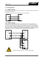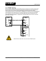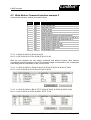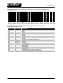
1
Documentation of the LinRS Interface for the following Controllers: - E1100-GP (-HC, -XC) - E1100-RS (-HC, -XC) - E1130-DP (-HC, -XC) - B1100-GP (-HC, -XC) - Series E1200 LinRS Interface V3.12/V4.0 User Manual LinMot LinRS Interface © 2010 NTI AG This work is protected by copyright. Under the copyright laws, this publication may not be reproduced or transmitted in any form, electronic or mechanical, including photocopying, recording, microfilm, storing in an information retrieval system, not even for didactic use, or translating, in whole or in part, without the prior written consent of NTI AG. LinMot® is a registered trademark of NTI AG. Note The information in this documentation reflects the stage of development at the time of press and is therefore without obligation. NTI AG reserves itself the right to make changes at any time and without notice to reflect further technical advance or product improvement. Document version 3.12 / June 2010 Page 2/59 User Manual LinRS Interface / 16/06/2010 NTI AG / LinMot LinMot LinRS Interface Table of Content 1 SYSTEM OVERVIEW..........................................................................................................5 1.1 REFERENCES.......................................................................................................................5 1.2 DEFINITIONS, ITEMS, SHORTCUTS.............................................................................................5 2 CONNECTING THE RS BUS...............................................................................................6 2.1 PIN OUT OF THE COM CONNECTOR (X5) (SERIES E1100 AND B1100)......................................6 2.2 PIN OUT OF THE SYSTEM CONNECTOR (X19) (SERIES E1200)...................................................6 2.3 PIN OUT OF THE CMD CONNECTOR (X7, X8):.........................................................................6 3 POWER UP BEHAVIOUR...................................................................................................7 3.1 ACTIVATING AND DEACTIVATING THE LINRS PROTOCOL................................................................7 3.2 ID AND BAUD RATE SELECTION...............................................................................................8 3.2.1 Baud Rate Selection...............................................................................................8 3.2.2 ID Selection............................................................................................................8 3.3 RS TOPOLOGIES..................................................................................................................9 3.3.1 RS232 Topology....................................................................................................9 3.3.2 RS422 Topology....................................................................................................9 3.3.3 RS485 Topology..................................................................................................10 4 LINRS MESSAGE FORMAT.............................................................................................11 4.1 ID ..................................................................................................................................11 4.2 LENGTH............................................................................................................................11 4.3 DATA...............................................................................................................................11 4.4 CHECKSUM........................................................................................................................11 5 MESSAGE DATA DEFINITIONS.......................................................................................12 5.1 MESSAGE MAIN ID ............................................................................................................12 6 RESPONSE REQUEST.....................................................................................................14 6.1 CONFIGURATION OF THE DEFAULT RESPONSE............................................................................14 6.2 REQUEST DEFAULT RESPONSE EXAMPLE.................................................................................15 6.3 DEFAULT MC RESPONSE REQUEST WITH STATUS WORD REQUEST EXAMPLE.................................16 7 WRITE CONTROL WORD.................................................................................................17 7.1 WRITE CONTROL WORD EXAMPLE 1.......................................................................................17 7.2 WRITE CONTROL WORD EXAMPLE 2.......................................................................................18 7.3 WRITE CONTROL WORD EXAMPLE 3.......................................................................................19 8 WRITE MOTION COMMAND INTERFACE.......................................................................20 8.1 WRITE MOTION COMMAND INTERFACE EXAMPLE 1.....................................................................20 8.2 WRITE MOTION COMMAND INTERFACE EXAMPLE 2.....................................................................21 9 PARAMETER GROUP......................................................................................................22 9.1 PARAMETER/VARIABLE READ RAM EXAMPLE...........................................................................23 9.2 PARAMETER WRITE RAM EXAMPLE........................................................................................23 10 PARAMETER CONFIGURATION GROUP.....................................................................25 ..........................................................................................................................................26 10.1 PARAMETER CONFIGURATION READ ROM VALUE EXAMPLE........................................................27 10.2 PARAMETER CONFIGURATION READ OUT CHANGED PARAMETERS..................................................28 10.3 PARAMETER CONFIGURATION READ OUT UPID LIST................................................................29 10.4 PARAMETER CONFIGURATION DEFAULTING SW-INSTANCE PARAMETERS.......................................30 NTI AG / LinMot User Manual LinRS Interface / 16/06/2010 Page 3/59 LinMot LinRS Interface 11 CURVE CONFIGURATION MESSAGE GROUP.............................................................31 11.1 READ CURVE FROM SERVO EXAMPLE...................................................................................34 11.2 WRITE CURVE TO SERVO EXAMPLE.....................................................................................36 12 COMMAND TABLE MESSAGE GROUP........................................................................38 12.1 READ COMMAND TABLE ENTRY FROM SERVO EXAMPLE...........................................................42 12.2 WRITE COMMAND TABLE ENTRY TO SERVO EXAMPLE..............................................................43 13 PROGRAM HANDLING MESSAGE GROUP..................................................................44 13.1 RESET SERVO CONTROLLER WITH RESPONSE AFTER COMPLETION...............................................44 13.2 RESET SERVO CONTROLLER WITH IMMEDIATE RESPONSE...........................................................45 13.3 STOP MC- AND APPLICATION SW.......................................................................................45 13.4 START MC- AND APPLICATION SW WITH RESPONSE AFTER COMPLETION......................................46 13.5 START MC- AND APPLICATION SW WITH IMMEDIATE RESPONSE.................................................47 14 READ ERROR INFO MESSAGE GROUP.......................................................................48 14.1 GET ERROR SHORT TEXT OF ACTUAL ERROR............................................................................48 14.2 GET ERROR SHORT TEXT OF DEFINED ERROR CODE...................................................................49 14.3 GET ERROR COUNTERS OF ERROR LOG AND TOTAL OCCURRED ERRORS..........................................50 14.4 GET ERROR LOG ENTRY......................................................................................................51 15 LINRS PARAMETERS....................................................................................................52 16 ERROR...........................................................................................................................57 16.1 LINRS ERROR CODES......................................................................................................57 17 TROUBLESHOOTING.....................................................................................................58 17.1 STOPPING LINRS ON B1100 CONTROLLERS.........................................................................58 18 CONTACT ADDRESSES................................................................................................59 Page 4/59 User Manual LinRS Interface / 16/06/2010 NTI AG / LinMot LinMot LinRS Interface 1 System Overview The LinMot servo controllers E1100-RS, E1100-GP, E1130-DP, the whole series E1200 and the B1100-GP support the LinRS communication profile. LinRS is a LinMot specific RS protocol to run the E1100 Servo controller over RS232, RS422 or RS485 serial links. When running the E1100 servo controller over an RS connection with LinRS, the configuration and debugging can be done over the CAN bus link. LinMotTalk supports an USB to CAN (Part No. 0150-3134 ) converter for this purpose. It is strongly recommended to use this USB to CAN converter, to avoid programming debugging disappointment. For the installation and use of the USB to CAN converter refer to document [3]. 1.1 References Ref Title Source 1 2 User Manual Motion Control SW LinMot E1100 Servo Controller Configuration over Fieldbus Interfaces Installation Guide USB-CAN Converter www.linmot.com www.linmot.com 3 www.linmot.com The documentation is distributed with the LinMot-Talk software. 1.2 Definitions, Items, Shortcuts Shortcut Meaning LM OS MC Intf Appl UPID CT Msg Cmd LinMot linear motor Operating System (Software) Motion Control (Software) Interface (Software) Application (Software) Unique Parameter ID (16 bit) Command Table Message Command NTI AG / LinMot User Manual LinRS Interface / 16/06/2010 Page 5/59 LinMot LinRS Interface 2 Connecting the RS bus 2.1 Pin Out of the COM Connector (X5) (Series E1100 and B1100) Over this connector the RS232 or the RS422/RS485 serial lines are available. This connector is available with all E1100 series servo controllers. DSBU 9 male: Pin 1 Pin 2 Pin 3 Pin 4 Pin 5 RS-485 Tx+ RS-232 TX RS-232 RX RS-485 Rx+ GND (100Ω) Pin 6 Pin 7 Pin 8 Pin 9 RS-485 RxRS-485 TxCAN L CAN H 2.2 Pin Out of the System Connector (X19) (Series E1200) Pin 1 Pin 2 Pin 3 Pin 4 Pin 5 Pin 6 Pin 7 Pin 8 Do not connect Do not connect RS232 RX GND GND RS232 TX Do not connect Do not connect 2.3 Pin Out of the CMD Connector (X7, X8): The CMD connector exists only on the E1100-RS(-HC/-XC), E1100-DP(-HC/-XC), series E1200 and B1100-GP(-HC/-XC) controllers, 2xRJ45 with 1:1 connected signals. Standard twisted pairs: 1/2, 3/6, 4/5, 7/8. Use Ethernet cables according the EIA / TIA 568A standard. Pin 1 RS485 Rx+ Pin 2 RS485 RxPin 3 RS485 Tx+ Pin 4/5 Ground (1kΩ) Pin 6 RS485 TxPin 7 CAN H Pin 8 CAN L Page 6/59 User Manual LinRS Interface / 16/06/2010 NTI AG / LinMot LinMot LinRS Interface 3 Power Up Behaviour The power up behaviour can be defined over the S3 switches and the S1 and S2 hex switches and the parameter configuration. So the servo controller can be configured over the LinRS protocol. It is possible to setup completely the controller over LinRS when the LinRS software has been installed. On the B1100 there are no switches to define the baud rate, ID and interface enable, for this reason all configuration has to be done by parameter with LinMotTalk 4 software over CAN-Bus. 3.1 Activating and Deactivating the LinRS Protocol Over the Interface Switch on the S3.4 switches the LinRS protocol can be activated (position On) or deactivated (position Off). This switch is not available on E1200 series controllers. S3 On - Off Interface CAN Term RS485 Term RS485/232 4 3 2 1 If the Interface Switch S3.4 is off during the system is booting, the LinRS will be deactivated for the rest of this power cycle. In this case the servo controller can normally be accessed with the LinMot-Talk software over the RS or CAN link, for configuration and testing. If the Interface Switch S3.4 is on during the system is booting, the LinRS protocol will be activated. The RS line of the servo controller is no longer available for the LinMot-Talk software, in this case configuring, debugging and testing can only be done over the CAN link. Now switching off the interface to off reactivates the RS line for the LinMot-Talk software, then switching on again, reinstall the LinRS protocol for the RS line, this enables some debugging capabilities without running the LinMot-Talk software over the CAN bus. It is recommended to use the USB to CAN converter, when working with the LinRS protocol for configuring and debugging. With the RS485/RS232 switch on S3 the bus driver can be selected. NTI AG / LinMot User Manual LinRS Interface / 16/06/2010 Page 7/59 LinMot LinRS Interface 3.2 ID and Baud Rate Selection With the default parameterization the baud rate can be selected over S1 and the ID is selected over S2. 3.2.1 Baud Rate Selection The baud rate can be defined over the S1 hex switch (default setting) or by parameter value. S1 Baud Rate Code Table S1 Value Selected Baud Rate 0 Undefined Baud Rate 1 4800Bit/s 2 9600 Bit/s 3 19200 Bit/s 4 38400 Bit/s 5 57600 Bit/s 6 115200 Bit/s 7 Undefined Baud Rate . Undefined Baud Rate 3.2.2 ID Selection Like the baud rate the protocol ID can be defined over the S2 hex switch (default setting), by parameter value or by the S1&S2 hex switches. S2 ID code table S2 Value Selected MACID 0 MACID = 00h 1 MACID = 01h 2 MACID = 02h . . F MACID = 0Fh S1&S2 ID code table S1 Value S2 Value 0 0 0 1 0 2 . . 1 0 . . F F Page 8/59 Selected MACID MACID = 00h MACID = 01h MACID = 02h . MACID = 10h MACID = FFh User Manual LinRS Interface / 16/06/2010 NTI AG / LinMot LinMot LinRS Interface 3.3 RS Topologies 3.3.1 RS232 Topology Over a RS232 line only one slave can be connected to the master, controlling several slaves needs several RS232 lines. The RS232 serial lines are only on the COM connector X5 available. Master PLC/IPC Slave E1100 3 Tx 2 Rx GND 5 Rx Tx GND 3.3.2 RS422 Topology With the RS422 topology several Slaves can be accessed. The master transmit lines are connected to all slave receives lines and all slave transmit lines are connected with master receive lines. With this topology debugging is quiet easy because master communication and slave communication is separated. The easiest way to loop through the communication lines at slave side, are over the X7/X8 RJ45 connectors with the RS/DP servo controllers. Activate RS485 Term on S3.2 (or S5.2 on E1200 series) on the last slave servo controller. Master PLC/IPC Slave 1 E1100 Tx Rx Rx Tx GND 5 GND Slave N E1100 Rx Tx 5 GND With B1100 the switch S4.1 has to be set to RS485 select! NTI AG / LinMot User Manual LinRS Interface / 16/06/2010 Page 9/59 LinMot LinRS Interface 3.3.3 RS485 Topology With the RS485 topology also several Slaves can be accessed. The master transmit lines are connected to all slave receives lines and all slave transmit lines are connected with master receive lines. With this topology debugging is quiet easy because master communication and slave communication is separated. The easiest way to loop through the communication lines at slave side, are over the X7/X8 RJ45 connectors with the RS/DP servo controllers, but at the first slave the RS485 AB lines from the master have to be connected with the Rx and the Tx signal lines. Activate RS485 Term on S3.2 on the last slave servo controller. Master PLC/IPC Slave 1 E1100 Tx Rx Rx Tx GND 5 GND Slave N E1100 Rx Tx 5 GND With B1100 the switch S4.1 has to be set to RS485 select! Page 10/59 User Manual LinRS Interface / 16/06/2010 NTI AG / LinMot LinMot LinRS Interface 4 LinRS Message Format The following tables define the principle structure of a LinRS Message. Header Start ID Header Data Len Start Data 1 Data Msg 0 ID Low 0..FFh 2..63 02h 0..FFh Length Count Checksum Calculation 01h Data 2 Msg ID High 0..FFh … Data n-1 Opt. Checksum Check- CheckSum Sum Low High 0..FFh 0..FFh 0..FFh 0..FFh Byte Nr Name Description Value 0 1 2 3 4 5 6 .. n+2 n+3 n+4 n+5/n+3 Start Header ID Length Start Data 0 Data 1 Msg ID Low Data 2 Msg ID High Data 3 .. Data n-1 Checksum Low Checksum High End Telegram Fix ID at telegram start ID of LinMot Controller Length of telegram data n Fix ID at telegram start Message Sub ID Message Main ID Message data 0 .. Message data n-1 Optional checksum Low Byte Optional checksum High Byte Fix ID at telegram end 01h 0..FFh 2..63 02h 0..FFh 0..FFh 0..FFh 0..FFh 0..FFh 0..FFh 0..FFh 04h End End Telegram 04h Data are transmitted lowest byte first highest byte last. Dummy Data could be added to get a fix master transmission length. 4.1 ID The ID is one byte that defines the address (ID) of the LinMot servo controller. This ID is defined by two Hex Switches or by a parameter. 4.2 Length The length defines the data length in bytes. 4.3 Data In the data fields the command specific data are transmitted. 4.4 Checksum The checksum field is optional. Two different methods are supported: • • Byte wise addition modulo 2^16 (fast and easy) CRC CCITT NTI AG / LinMot User Manual LinRS Interface / 16/06/2010 Page 11/59 LinMot LinRS Interface 5 Message Data Definitions 5.1 Message Main ID The Message object are identified in a first level by following main Message IDs Message Main ID 00h 01h 02h 03h 04h 05h 06h 07h 08h B1100 Description Yes Yes Yes Yes Yes - Response Request / Response itself Write Control Word Write Motion Command Interface Parameter Message Group with default Response Curve Configuration Message Group Parameter Configuration Message Group Program Handling Message Group Read Error Info Message Group Command Table Configuration Message Group In the easiest way of using the LinRS protocol, only the Messages with the Main IDs (0), 1 and 2 are needed to control the behavior of the servo controller. The other Main messages IDs are only needed if configuration or setup functionality over the LinRS protocol is needed and supported. In these cases a much deeper integration of the LinMot servo controller into the superior PLC/IPC is supported and needed. As an alternative to this, LinMot offers a configuration service, which means you can store your configuration with LinMot and order the servo controller with installed firmware and configuration (parameter and curves). In many cases this will be the more cost effective solution. Page 12/59 User Manual LinRS Interface / 16/06/2010 NTI AG / LinMot LinRS Interface LinMot For debugging reasons and to get familiar with the LinRS protocol the LinMot-Talk has an integrated LinRS test tool (Tools\LinRS test Tool). Together with the USB to CAN converter the steps could be followed directly as shown below. NTI AG / LinMot User Manual LinRS Interface / 16/06/2010 Page 13/59 LinMot LinRS Interface 6 Response Request The response to the response request is added to the configured response data, or set to the configured reserved space. Message Main ID Message Sub ID Description 00h 00h 00h 00h 00h 00h 00h 00h 00h 00h 00h 00h 01h 02h 03h 04h 30h 40h 50h 60h 7yh 8yh Default MC Response Answer (Slave) Default MC Response Request (Master) Default MC Response Request with Status Word Request (Master) Default MC Response Request with Warn Word Request (Master) Default MC Response Request with State Var Request (Master) Slave Response to Master Parameter Request Slave Response to Master Curve Request Reserved Slave Memory Group Response Slave Response to Master Program Handling Request Slave Response to Master Read Error Requests Slave Response to Master Command Table Request Every time the controller has accepted a Message, it will respond with a message itself. Normally the response contains the configured data. 6.1 Configuration of the Default Response The content of the default response can be configured, so the information for the normal operation can be adapted to the application needs. The order of the information is the same as they appear in the LinMot-Talk configuration tool. The Default Response is normally responded within the time >0.5ms..<1.5ms. The bold named entries are configured in default configuration (factory setting) of the LinRS firmware installation. Name Format Description Communication State Status Word State Var Error Code Warn Word Echo MC Intf Header Monitoring Channel 1 Monitoring Channel 2 MC Response 1 bytes 2 bytes 2 bytes 2 bytes 2 bytes 2 bytes 4 bytes 4 bytes 4 bytes Page 14/59 Status of communication (Checksum error,..) (Default Cfg) Status Word bit coded (Default Cfg) High byte state number, low byte state depending (Default Cfg) Error Code Warn Word bit coded Echo of the motion command interface header Monitoring Channel 1 Data (Default Cfg) Monitoring Channel 2 Data Place holder for a response request User Manual LinRS Interface / 16/06/2010 NTI AG / LinMot LinMot LinRS Interface 6.2 Request Default Response Example The following example documents a default response request, the controller will answer with the configured default response. This request could be used to monitor state changes or direct variable changes. Request: default response Byte Offset 0 1 2 3 4 5 6 Value Description 01h 11h 03h 02h 01h 00h 04h Fix ID Telegram start Response node ID Telegram length Fix ID start data Message Sub ID (default response request) Message Main ID (Response) Fix ID telegram end Response: Default Response Byte Value Offset 0 1 2 3 4 5 6 7 8 9 10 11 12 13 14 15 01h 11h 0Ch 02h 00h 00h 00h 37h 4Ch C2h 08h 9Dh FCh FFh FFh 04h Description Fix ID telegram start MACID Data length Fix ID start data Sub ID: Default Response Main ID: Response Message Communication State ok Status Word Low Byte Status Word High Byte State Var Low Byte State Var High Byte (MainState) Actual Position Low Word Low Byte Actual Position Low Word High Byte Actual Position High Word Low Byte Actual Position High Word High Byte Fix ID telegram end Example: Tx: 01 11 03 02 01 00 04 Rx: 01 11 0C 02 00 00 00 37 4C C2 08 9D FC FF FF 04 NTI AG / LinMot User Manual LinRS Interface / 16/06/2010 Page 15/59 LinMot LinRS Interface 6.3 Default MC Response Request with Status Word Request Example The following example documents a Default MC Response Request with Status Word Request, the controller will answer with the configured default response and adds the Status Word in a 4Byte Container at the end of the data section. Request: Default MC Response Request with Status Word Request Byte Value Description Offset 0 1 2 3 4 5 6 01h 11h 03h 02h 02h 00h 04h Fix ID Telegram start Response node ID Telegram length Fix ID start data Message Sub ID (default response request) Message Main ID (Response) Fix ID telegram end Response: Default MC Response Request with Status Word Request Byte Value Description Offset 0 1 2 3 4 5 6 7 8 9 10 11 12 13 14 15 16 17 18 19 01h 11h 10h 02h 00h 00h 00h 37h 4Ch C2h 08h 9Dh FCh FFh FFh B4h 00h 00h 00h 04h Fix ID telegram start MACID Data length Fix ID start data Sub ID: Default Response with Status Word Main ID: Response Message Communication State ok Status Word Low Byte Status Word High Byte State Var Low Byte State Var High Byte (MainState) Actual Position Low Word Low Byte Actual Position Low Word High Byte Actual Position High Word Low Byte Actual Position High Word High Byte Low Byte Status Word High Byte Status Word No Meaning No Meaning Fix ID telegram end Examples: Tx: 01 11 03 02 02 00 04 ; Request Default Response with Status Word Rx: 01 11 10 02 00 00 00 B4 00 00 02 D5 6A 10 00 B4 00 00 00 04 Tx: 01 11 03 02 03 00 04 ; Request Default Response with Warn Word Rx: 01 11 10 02 00 00 00 B4 00 00 02 D5 6A 10 00 80 00 00 00 04 Tx: 01 11 03 02 04 00 04 ; Request Default Response with State Var Rx: 01 11 10 02 00 00 00 B4 00 00 02 D5 6A 10 00 00 02 00 00 04 Page 16/59 User Manual LinRS Interface / 16/06/2010 NTI AG / LinMot LinMot LinRS Interface 7 Write Control Word With the access to the control Word the main state machine could be controlled. Message Main ID Message Sub ID Description 01h 00h Write Control Word With the following examples the first steps in runtime programming should be explained. To this message request the LinMot servo controller will always answer with the default motion response. 7.1 Write Control Word example 1 With this control word command the lock state is cleared Request: Write Control Word (Clear Control Word) Byte Value Description Offset 0 1 2 3 4 5 6 7 8 01h 11h 05h 02h 00h 01h 00h 00h 04h Fix ID Telegram start Destination node ID Telegram length Fix ID start data Message Sub ID Message Main ID (Write Control Word) Control Word Low Byte Control Word High Byte Fix ID telegram end This request is answered with the Default Response. Example: Tx: 01 11 05 02 00 01 00 00 04 Rx: 01 11 0C 02 00 00 00 B4 40 00 02 AB 00 00 00 04 NTI AG / LinMot User Manual LinRS Interface / 16/06/2010 Page 17/59 LinMot LinRS Interface 7.2 Write Control Word example 2 With this control word command causes a transition to enable state and starts homing. Request: Write Control Word (Set all Bits for Operation and Home Flag) Byte Value Description Offset 0 1 2 3 4 5 6 7 8 01h 11h 05h 02h 00h 01h 3Fh 08h 04h Fix ID Telegram start Destination node ID Telegram length Fix ID start data Message Sub ID Message Main ID (Write Control Word) Control Word Low Byte Control Word High Byte Fix ID telegram end Example: Tx: 01 11 05 02 00 01 3F 08 04 Rx: 01 11 0C 02 00 00 00 B6 40 00 02 A8 00 00 00 04 To detect when the homing sequence has finished, poll the controller until the low byte in the StateVar is 0Fh and the main state = 09h (homing) high byte of the state var. Example: Tx: 01 11 05 02 00 01 3F 08 04 Rx: 01 11 0C 02 00 00 00 B7 22 01 09 65 0E FB FF 04 Tx: 01 11 05 02 00 01 3F 08 04 Rx: 01 11 0C 02 00 00 00 B7 22 01 09 8B A3 F7 FF 04 Tx: 01 11 05 02 00 01 3F 08 04 Rx: 01 11 0C 02 00 00 00 B7 62 0C 09 4D 24 FF FF 04 Tx: 01 11 05 02 00 01 3F 08 04 Rx: 01 11 0C 02 00 00 00 37 4C 0F 09 DA FB FF FF 04 -> Homing finished Page 18/59 User Manual LinRS Interface / 16/06/2010 NTI AG / LinMot LinMot LinRS Interface 7.3 Write Control Word example 3 With this control word command the normal operation is enabled. Request: Write Control Word (Set all Bits for Operation and Reset Home Flag) Byte Value Description Offset 0 1 2 3 4 5 6 7 8 01h 11h 05h 02h 00h 01h 3Fh 00h 04h Fix ID Telegram start Destination node ID Telegram length Fix ID start data Message Sub ID Message Main ID (Write Control Word) Control Word Low Byte Control Word High Byte Fix ID telegram end Example: Tx: 01 11 05 02 00 01 3F 00 04 Rx: 01 11 0C 02 00 00 00 37 4C 00 09 3C FC FF FF 04 Poll again to make sure main state 08h is reached. Tx: 01 11 05 02 00 01 3F 00 04 Rx: 01 11 0C 02 00 00 00 37 4C C0 08 DA FB FF FF 04 reached with homed flag set NTI AG / LinMot -> ‘Operation Enabled’ state User Manual LinRS Interface / 16/06/2010 Page 19/59 LinMot LinRS Interface 8 Write Motion Command Interface With the access to the Motion Command Interface of the MC-SW [1], the run time motion could be controlled. There are a lot of different motion commands, which are described in [1] for the different needs of the applications. Message Main ID Message Sub ID Description 02h 00h Write Motion Control Interface 8.1 Write Motion Command Interface example 1 With this motion command a VA-interpolator motion with default parameters for (max. velocity and acceleration and deceleration) to the target position 10mm is defined. Byte Offset Value Description 0 1 2 3 4 5 6 7 8 9 10 11 12 01h 11h 09h 02h 00h 02h 01h 02h A0h 86h 01h 00h 04h Fix ID Telegram start Destination node ID Telegram length Fix ID start data Message Sub ID Message Main ID (Motion Command Interface) Motion Cmd Intf Header Low Byte (count =1) Sub ID =0 Motion Cmd Intf Header High Byte Master ID =2 Target Position lowest byte Target Position middle low byte Target Position middle high byte Target Position highest byte Fix ID telegram end Example: Tx: 01 11 09 02 00 02 01 02 A0 86 01 00 04 Rx: 01 11 0C 02 00 00 00 37 68 A1 08 8B FC FF FF 04 Page 20/59 User Manual LinRS Interface / 16/06/2010 NTI AG / LinMot LinMot LinRS Interface 8.2 Write Motion Command Interface example 2 Go back with the same motion command to 0mm. Byte Offset Value Description 0 1 2 3 4 5 6 7 8 9 10 11 12 01h 11h 09h 02h 00h 02h 02h 02h 00h 00h 00h 00h 04h Fix ID Telegram start Destination node ID Telegram length Fix ID start data Message Sub ID Message Main ID (Motion Command Interface) Motion Cmd Intf Header Low Byte (count =1) Sub ID =0 Motion Cmd Intf Header High Byte Master ID =2 Target Position lowest byte Target Position middle low byte Target Position middle high byte Target Position highest byte Fix ID telegram end Tx: 01 11 09 02 00 02 02 02 00 00 00 00 04 Rx: 01 11 0C 02 00 00 00 37 28 A2 08 5E 81 01 00 04 With the next example the VAI motion command with defined Position, Max Velocity, Acceleration and Deceleration is used. The message length is increased to 15h, to debug the send data push the read button in the Control Panel. Tx: 01 11 15 02 00 02 03 01 F0 49 02 00 40 42 0F 00 40 42 0F 00 40 42 0F 00 04 Rx: 01 11 0C 02 00 00 00 37 0D D3 08 F3 49 02 00 04 Tx: 01 11 15 02 00 02 04 01 B0 3C FF FF 40 42 0F 00 40 42 0F 00 40 42 0F 00 04 Rx: 01 11 0C 02 00 00 00 37 49 94 08 61 3D FF FF 04 NTI AG / LinMot User Manual LinRS Interface / 16/06/2010 Page 21/59 LinMot LinRS Interface 9 Parameter Group With the parameter group, parameter can be changed or read. Within the MC SW two different kinds of parameters are supported: • • Live Parameters (during MC runtime, Message Sub ID’s 00h and 01h) Configuration Parameters While live parameters can be changed during the MC SW is running the configuration parameters affects the behavior of its SW instance only after a restart of it. A Reset command or Power cycle restarts all SW instances. The parameters are accessed with a 16 Bit Unique Parameter ID (UPID). All parameters values are mapped in a 4 byte value memory area. With bit parameters the lowest bit of parameter value memory field is relevant, a byte parameter in the lowest byte and word parameter into the two lower bytes. Message Main ID Message Sub ID B1100 Description 03h 03h 03h 03h 03h 03h 03h 03h 00h 01h 02h 03h 04h 05h 06h 07h Yes Yes Yes Yes - Read RAM value with MC Default Response Write RAM value with MC Default Response Read ROM value with MC Default Response Write ROM value with MC Default Response Write RAM and ROM value with MC Default Response Get minimal value of parameter with MC Default Response Get maximal value of parameter with MC Default Response Get default value of parameter with MC Default Response 03h 03h 03h 03h 11h 12h 13h 14h - Set OS (Operating System) ROM parameter values to default Set MC (Motion Control) ROM parameter values to default Set Interface ROM parameter values to default Set Application ROM parameter values to default Page 22/59 User Manual LinRS Interface / 16/06/2010 NTI AG / LinMot LinMot LinRS Interface 9.1 Parameter/Variable Read RAM example With this command example the RAM value of the UPID 13A2h (P Gain Position Controller, for B1100 controllers it is UPID 6198h) is read. With the default MC response the requested value is added in the last 4 bytes of it. Byte Offset Value Description 0 1 2 3 4 5 6 7 8 01h 11h 05h 02h 00h 03h A2h 13h 04h Fix ID Telegram start Destination node ID Telegram length Fix ID start data Message Sub ID (Read Ram Value) Message Main ID (Parameter) UPID Low Byte (P Gain Position Controller) UPID High Byte (P Gain Position Controller) Fix ID telegram end Tx: 01 11 05 02 00 03 A2 13 04 Rx: 01 11 10 02 00 00 00 37 4C C2 08 AA 06 00 00 0A 00 00 00 04 9.2 Parameter Write RAM example With this command example the RAM value of the UPID 13A2h (P Gain Position Controller, for B1100 controllers it is UPID 6198h) is changed to 11. Byte Value Description Offset 0 1 2 3 4 5 6 7 8 9 10 11 12 01h 11h 09h 02h 01h 03h A2h 13h 0Bh 00h 00h 00h 04h Fix ID Telegram start Destination node ID Telegram length Fix ID start data Message Sub ID (Write Ram Value) Message Main ID (Parameter) UPID Low Byte (P Gain Position Controller) UPID High Byte (P Gain Position Controller) Parameter value low word low byte Parameter value low word high byte Parameter value high word low byte Parameter value high word high byte Fix ID telegram end Tx: 01 11 09 02 01 03 A2 13 0B 00 00 00 04 Rx: 01 11 0C 02 00 00 00 37 4C C0 08 BF FB FF FF 04 Reading the parameter again shows the changed value: Tx: 01 11 05 02 00 03 A2 13 04 Rx: 01 11 10 02 00 00 00 37 4C C0 08 BF FB FF FF 0B 00 00 00 04 NTI AG / LinMot User Manual LinRS Interface / 16/06/2010 Page 23/59 LinMot LinRS Interface Reading the ROM value of the same parameter shows that it is still unchanged 0Ah. Tx: 01 11 05 02 02 03 A2 13 04 Rx: 01 11 10 02 00 00 00 37 4C C0 08 BF FB FF FF 0A 00 00 00 04 Write 12 (0Ch) to the ROM value of the same parameter. Tx: 01 11 09 02 03 03 A2 13 0C 00 00 00 04 Rx: 01 11 0C 02 00 00 00 37 4C C2 08 AB 09 00 00 04 Reading the ROM value of the same parameter shows that it is still unchanged 0Ch. This change will affect the position controller behavior only after a restart of the MC-SW, for this reason it is recommended to change the ROM values only in the stopped MC-SW mode. Tx: 01 11 05 02 02 03 A2 13 04 Rx: 01 11 10 02 00 00 00 37 4C C2 08 AB 09 00 00 0C 00 00 00 04 The following sequence shows the behavior of the write RAM nad ROM command (Message Sub ID 04h) to the same parameter with UPID 13A2h P-Gain Position controller Set A (UPID 6198h for B1100). Write 09h to Ram and ROM Tx: 01 11 09 02 04 03 A2 13 09 00 00 00 04 Rx: 01 11 0C 02 00 00 00 37 4C C2 08 95 09 00 00 04 Reading changed RAM value Tx: 01 11 05 02 00 03 A2 13 04 Rx: 01 11 10 02 00 00 00 37 4C C2 08 EB 09 00 00 09 00 00 00 04 Reading changed ROM value Tx: 01 11 05 02 02 03 A2 13 04 Rx: 01 11 10 02 00 00 00 37 4C C2 08 95 09 00 00 09 00 00 00 04 Page 24/59 User Manual LinRS Interface / 16/06/2010 NTI AG / LinMot LinMot LinRS Interface 10 Parameter Configuration Group The parameter Configuration Group Messages could be used to read out a configuration, and/or write a configuration. For configuring it is needed to stop the MC-SW of the servo controller first (Program Handling Message Group), and after configuring the controller (re)start the MC-SW again. Message Main ID Message Sub ID Description 05h 05h 05h 05h 05h 05h 05h 05h 05h 05h 05h 05h 05h 05h 05h 00h 01h 03h 04h 05h 06h 07h 08h 09h 0Ah 0Bh 0Ch 0Dh 0Eh 0Fh Read ROM value Write ROM value Get parameter address usage Get parameter type Get minimal value of parameter Get maximal value of parameter Get default value of parameter Start Get Modified UPID List Get Next Modified UPID Start Get UPID List Get Next UPID Set OS (Operating System) ROM parameter values to default Set MC (Motion Control) ROM parameter values to default Set Interface ROM parameter values to default Set Application ROM parameter values to default NTI AG / LinMot User Manual LinRS Interface / 16/06/2010 Page 25/59 LinMot LinRS Interface 11 10 9 8 7 6 5 4 RAM Read 12 RAM Write 13 ROM Read 14 ROM Write 15 Life Parameter calculationNot used for Hash Meaning of the bits in the response to the telegram “Get parameter address usage” Address Usage: 3 2 1 0 Meaning of the code in the response to the telegram “Get parameter type” Supported Parameter Types: Type Code Bit Length Description 00h 01h 02h 03h 04h 05h 06h 07h 08h 09h 0Ah 0Bh 0Ch 0Dh 0Eh 0Fh Page 26/59 1 8 8 16 16 32 32 32 #Char x 8 #Char x 8 1 16 8 16 32 32 BOOL UINT8 SINT8 UINT16 SINT16 UINT32 SINT32 LIN_FLOAT ( not used as parameter) STRING CAP_DIR RADIO_DIR_BIT RADIO_DIR16 ENUM_DIR8 ENUM_DIR16 STRINGLET (Part of String 4 Characters) CAP_DIRLET (Part of String 4 Characters) User Manual LinRS Interface / 16/06/2010 NTI AG / LinMot LinMot LinRS Interface 10.1 Parameter Configuration Read ROM value example With command the RAM value of the UPID 13A2h (P Gain Position Controller, UPID 6198h for B1100) is read. With the default MC response the requested value is added in the last 4 bytes of it. Request: Read ROM value of UPID Byte Value Offset 0 1 2 3 4 5 6 7 8 01h 11h 05h 02h 00h 05h A2h 13h 04h Description Fix ID Telegram start Destination node ID Telegram length Fix ID start data Message Sub ID (Cfg Read ROM Value) Message Main ID (Parameter Configuration) UPID Low Byte (P Gain Position Controller) UPID High Byte (P Gain Position Controller) Fix ID telegram end Configuration Response: Read ROM value of UPID Byte Value Description Offset 0 1 2 3 4 5 6 7 8 9 10 11 12 13 01h 11h 0Ah 02h 50h 00h 00h A2h 13h 09h 00h 00h 00h 04h Fix ID Telegram start Destination node ID Telegram length Fix ID start data Message Sub ID (Cfg Read ROM Value Response) Message Main ID (Response) Communication state UPID Low Byte (P Gain Position Controller) UPID High Byte (P Gain Position Controller) Parameter value low word low byte Parameter value low word high byte Parameter value high word low byte Parameter value high word high byte Fix ID telegram end Examples: Stopping MC SW: Tx: 01 11 03 02 03 06 04 Rx: 01 11 0C 02 00 00 00 00 00 00 00 87 00 00 00 04 ; MC default response Reading the P Gain Position Controller Set A (UPID: 13A2h) ROM value: Tx: 01 11 05 02 00 05 A2 13 04 Rx: 01 11 0A 02 50 00 00 A2 13 09 00 00 00 04 Writing 16=00000010h the P Gain Position Controller Set A (UPID: 13A2h) ROM value: Tx: 01 11 09 02 01 05 A2 13 10 00 00 00 04 Rx: 01 11 0A 02 51 00 00 A2 13 10 00 00 00 04 Reading again the P Gain Position Controller Set A (UPID: 13A2h) ROM value: Tx: 01 11 05 02 00 05 A2 13 04 Rx: 01 11 0A 02 50 00 00 A2 13 10 00 00 00 04 NTI AG / LinMot User Manual LinRS Interface / 16/06/2010 Page 27/59 LinMot LinRS Interface Reading the Parameter address acces of P Gain Position Controller Set A (UPID: 13A2h): Tx: 01 11 05 02 03 05 A2 13 04 Rx: 01 11 0A 02 53 00 00 A2 13 0F 01 00 00 04 ; RAM/ROM Read/Write and life Reading the Parameter Type of P Gain Position Controller Set A (UPID: 13A2h): Tx: 01 11 05 02 04 05 A2 13 04 Rx: 01 11 0A 02 54 00 00 A2 13 03 00 00 00 04 ; Par Type UINT16 Reading Min Value the P Gain Position Controller Set A (UPID: 13A2h): Tx: 01 11 05 02 05 05 A2 13 04 Rx: 01 11 0A 02 55 00 00 A2 13 00 00 00 00 04 Reading Max Value the P Gain Position Controller Set A (UPID: 13A2h): Tx: 01 11 05 02 06 05 A2 13 04 Rx: 01 11 0A 02 56 00 00 A2 13 FF FF 00 00 04 Reading Default Value the P Gain Position Controller Set A (UPID: 13A2h): Tx: 01 11 05 02 07 05 A2 13 04 Rx: 01 11 0A 02 57 00 00 A2 13 0F 00 00 00 04 10.2 Parameter Configuration read out changed Parameters This feature is only available on E1100 controller types: With the commands ‘Start Get Modified UPID List’ and ‘Get Next Modified UPID’ for each SW layer the changed parameters of the actual configuration could be read out the servo controller. With this functionality the whole parameter configuration of the servo controller could be read out and stored in the PC/ PLC. Each firmware layer has its own range of UPIDs for its parameters. Layer UPID Range Layer name 1 2 3 4 0000h…0EFFh 1000h…1EFFh 2000h…2EFFh 3000h…3EFFh Operating System Motion Control SW Interface Software Application In the following example the changed parameters of the Intf SW (LinRS), in the example the 4 listed UPID’s are changed: UPID: UPID: UPID: UPID: 200Eh, Baud Rate Source Select, 2012h, Baud Rate Parameter Def, 206Ch, MACID Source Select, 2076h, MACID Parameter Value, Value: 00000002h, By Parameter Value: 00000008h, 38400 Baud Value: 00000003h, By Parameter Value: 00000011h, MACID Tx: 01 11 05 02 08 05 00 20 04 Rx: 01 11 0A 02 58 00 00 00 20 00 00 00 00 04 Tx: 01 11 05 02 09 05 00 20 04 Rx: 01 11 0A 02 59 00 00 0E 20 02 00 00 00 04 Tx: 01 11 05 02 09 05 00 20 04 Rx: 01 11 0A 02 59 00 00 12 20 08 00 00 00 04 Tx: 01 11 05 02 09 05 00 20 04 Rx: 01 11 0A 02 59 00 00 6C 20 03 00 00 00 04 Tx: 01 11 05 02 09 05 00 20 04 Rx: 01 11 0A 02 59 00 00 76 20 11 00 00 00 04 Tx: 01 11 05 02 09 05 00 20 04 Page 28/59 ; init read out changed Intf Par (LinRS) ; get next changed Intf parameter ; UPID: 200Eh, Value; 00000002h ; get next changed Intf parameter ; UPID: 2012h, Value; 00000008h ; get next changed Intf parameter ; UPID: 206Ch, Value; 00000003h ; get next changed Intf parameter ; UPID: 2076h, Value; 00000011h ; get next changed Intf parameter User Manual LinRS Interface / 16/06/2010 NTI AG / LinMot LinMot LinRS Interface Rx: 01 11 0A 02 59 00 C6 C7 20 01 00 00 00 04 ; UPID: 20C7h, Value; 00000001h The Communication state C6h indicates, that this was the last parameter To read out the changed parameters of MC-SW layer start as follows Tx: 01 11 05 02 08 05 00 10 04 ; init read out changed MC-SW Par Rx: 01 11 0A 02 58 00 00 00 10 00 00 00 00 04 Tx: 01 11 05 02 09 05 00 00 04 ; get next changed parameter Rx: 01 11 0A 02 59 00 00 37 10 07 00 00 00 04 ; UPID: 1037h, Value; 00000007h 10.3 Parameter Configuration Read out UPID List This feature is only available on E1100 controller types: With the commands ‘Start Get UPID List’ and ‘Get Next UPID’ for each SW layer all parameters of the actual configuration can be read out from the servo controller. With this functionality a parameter list of the servo controller can be read out and stored in the PC/PLC. In a second step with the request read ROM value all the values of the list can be read out. Request: Get Next UPID Byte Offset 0 1 2 3 4 5 6 7 8 Value Description 01h 11h 05h 02h 0Bh 05h 00h 00h 04h Fix ID Telegram start Destination node ID Telegram length Fix ID start data Message Sub ID (Get Next UPID) Message Main ID (Parameter Configuration) Not used, don’t have to be transmitted Not used, don’t have to be transmitted Fix ID telegram end Configuration Response: Get Next UPID Byte Value Description Offset 0 1 2 3 4 5 6 7 8 9 10 11 12 13 NTI AG / LinMot 01h 11h 0Ah 02h 5Bh 00h 00h A2h 13h 09h 00h 00h 00h 04h Fix ID Telegram start Destination node ID Telegram length Fix ID start data Message Sub ID (Cfg Read ROM Value) Message Main ID (Response) Communication state Found UPID Low Byte Found UPID High Byte Address Usage low byte of found UPID Address Usage high byte of found UPID Parameter Type low byte of found UPID Parameter Type high byte of found UPID Fix ID telegram end User Manual LinRS Interface / 16/06/2010 Page 29/59 LinMot LinRS Interface The following example shows the principle of reading the UPID List of a SW instance, if generating a configuration out of this list all UPIDs with the ‘ROM write’ address usage bit set have to be read out with the get ROM value command. Tx: 01 11 05 02 0A 05 00 20 04 Rx: 01 11 0A 02 5A 00 00 00 20 00 00 00 00 04 Tx: 01 11 05 02 0B 05 00 20 04 Rx: 01 11 0A 02 5B 00 00 08 20 0D 00 0A 00 04 … Tx: 01 11 05 02 0B 05 00 20 04 Rx: 01 11 0A 02 5B 00 00 36 21 01 10 03 00 04 Tx: 01 11 05 02 0B 05 00 20 04 Rx: 01 11 0A 02 5B 00 00 37 21 01 10 03 00 04 Tx: 01 11 05 02 0B 05 00 20 04 Rx: 01 11 0A 02 5B 00 C6 37 21 01 10 03 00 04 ; start Get UPID List Intf SW layer ; UPID 2008h, AU: 000Dh Type: 000Ah ; UPID 2136h, AU: 1001h Type: 0003h ; UPID 2137h, AU: 1001h Type: 0003h ; UPID 2137h, AU: 1001h Type: 0003h 10.4 Parameter Configuration Defaulting SW-Instance Parameters This feature is only for E1100 controllers: Before writing the parameters of a SW instance it is advised to set all parameters of the corresponding SW instance to default values. This can be done with a single parameter configuration message. The response is given after the defaulting of the SW instance is completed could be more than 1s. Examples: Defaulting the parameters of the OS-SW: Tx: 01 11 05 02 0C 05 00 00 04 Rx: 01 11 0A 02 5C 00 00 00 00 01 00 00 00 04 Defaulting the parameters of the MC-SW: Tx: 01 11 05 02 0D 05 00 00 04 Rx: 01 11 0A 02 5D 00 00 00 00 02 00 00 00 04 Defaulting the parameters of the Interface SW: Tx: 01 11 05 02 0E 05 00 00 04 Rx: 01 11 0A 02 5E 00 00 00 00 03 00 00 00 04 Defaulting the parameters of the Application SW: Tx: 01 11 05 02 0F 05 00 00 04 Rx: 01 11 0A 02 5F 00 00 00 00 04 00 00 00 04 Page 30/59 User Manual LinRS Interface / 16/06/2010 NTI AG / LinMot LinMot LinRS Interface 11 Curve Configuration Message Group Only for E1100 controllers: With the Curve Message Group, curves can be read out or written from/to the servo controller. To store a new curves in the ROM the MC SW layer has to be stopped. Message Message Description Main ID Sub ID 04h 04h 04h 04h 04h 04h 04h 04h 04h 00h 01h 02h 04h 05h 06h 08h 09h 0Ah Save Curves from RAM to FLASH (MC SW has to be stopped) Delete all Curves in RAM Delete Curve in RAM Add Curve to RAM (Define Info Block Size and Data Block Size) Write Curve Info Block Write Curve Data Block Read Curve Info Block Size and Data Block Size Read Curve Info Block Read Curve Data Block Request: Save Curves from RAM to FLASH Byte Value Description Offset 0 1 2 3 4 5 6 01h 11h 03h 02h 00h 04h 04h Fix ID Telegram start Destination node ID Telegram length Fix ID start data Message Sub ID (Save curves from RAM to FLASH) Message Main ID (Curve Message) Fix ID telegram end Configuration Response: Save Curves from RAM to FLASH Byte Value Description Offset 0 1 2 3 4 5 6 7 8 9 10 11 12 13 01h 11h 0Ah 02h 40h 00h 00h 00h 00h 09h 00h 00h 00h 04h Fix ID Telegram start Destination node ID Telegram length Fix ID start data Message Sub ID (Curve Cfg Response) Message Main ID (Response) Communication state No meaning (low byte curve ID) No meaning (high byte curve ID) No meaning (response data low word low byte) No meaning (response data low word high byte) No meaning (response data high word low byte) No meaning (response data high word high byte) Fix ID telegram end Example: Tx: 01 11 03 02 00 04 04 Rx: 01 11 0A 02 40 00 00 00 00 00 00 00 00 04 NTI AG / LinMot ; timeout 10s User Manual LinRS Interface / 16/06/2010 Page 31/59 LinMot LinRS Interface Request: Delete all Curves in RAM With this command all curves defined are deleted in RAM. Byte Value Description Offset 0 1 2 3 4 5 6 01h 11h 03h 02h 01h 04h 04h Fix ID Telegram start Destination node ID Telegram length Fix ID start data Message Sub ID (Delete all Curves in RAM) Message Main ID (Curve Message) Fix ID telegram end Configuration Response: Delete all Curves in RAM Byte Value Description Offset 0 1 2 3 4 5 6 7 8 9 10 11 12 13 01h 11h 0Ah 02h 40h 00h 00h 00h 00h 09h 00h 00h 00h 04h Fix ID Telegram start Destination node ID Telegram length Fix ID start data Message Sub ID (Curve Cfg Response) Message Main ID (Response) Communication state No meaning (low byte curve ID) No meaning (high byte curve ID) No meaning (response data low word low byte) No meaning (response data low word high byte) No meaning (response data high word low byte) No meaning (response data high word high byte) Fix ID telegram end Example: Tx: 01 11 03 02 01 04 04 Rx: 01 11 0A 02 40 00 00 00 00 00 00 00 00 04 Page 32/59 User Manual LinRS Interface / 16/06/2010 NTI AG / LinMot LinMot LinRS Interface Request: Delete Curve in RAM With this command the curve with ID 1 defined is deleted in RAM. Byte Value Description Offset 0 1 2 3 4 5 6 7 8 01h 11h 03h 02h 02h 04h 01h 00h 04h Fix ID Telegram start Destination node ID Telegram length Fix ID start data Message Sub ID (Delete Curve in RAM) Message Main ID (Curve Message) Curve ID low byte Curve ID high byte Fix ID telegram end Configuration Response: Delete Curve in RAM Byte Value Description Offset 0 1 2 3 4 5 6 7 8 9 10 11 12 13 01h 11h 0Ah 02h 40h 00h 00h 01h 00h 09h 00h 00h 00h 04h Fix ID Telegram start Destination node ID Telegram length Fix ID start data Message Sub ID (Curve Cfg Response) Message Main ID (Response) Communication state low byte curve ID high byte curve ID No meaning (response data low word low byte) No meaning (response data low word high byte) No meaning (response data high word low byte) No meaning (response data high word high byte) Fix ID telegram end Example: Tx: 01 11 05 02 02 04 01 00 04 Rx: 01 11 0A 02 40 00 00 01 00 00 00 00 00 04 NTI AG / LinMot User Manual LinRS Interface / 16/06/2010 Page 33/59 LinMot LinRS Interface 11.1 Read Curve From Servo Example Only for E1100 controllers: For a detailed description about the saving structure of a curve refer to [2]. In the following example the curve with ID = 1 is read from the servo controller Reading Curve 1 Info Block and Data Block size: Tx: 01 11 05 02 08 04 01 00 04 Rx: 01 11 0A 02 40 00 00 01 00 46 00 54 00 04 ; info block: 46bytes, data block: 54bytes Reading Curve 1 Info Block Data: Tx: 01 11 05 02 09 04 01 00 04 Rx: 01 11 0A 02 40 00 04 01 00 46 00 03 00 04 Tx: 01 11 05 02 09 04 01 00 04 Rx: 01 11 0A 02 40 00 04 01 00 15 00 04 00 04 Tx: 01 11 05 02 09 04 01 00 04 Rx: 01 11 0A 02 40 00 04 01 00 53 69 6E 52 04 Tx: 01 11 05 02 09 04 01 00 04 Rx: 01 11 0A 02 40 00 04 01 00 69 73 65 00 04 Tx: 01 11 05 02 09 04 01 00 04 Rx: 01 11 0A 02 40 00 04 01 00 00 00 00 00 04 Tx: 01 11 05 02 09 04 01 00 04 Rx: 01 11 0A 02 40 00 04 01 00 00 00 00 00 04 Tx: 01 11 05 02 09 04 01 00 04 Rx: 01 11 0A 02 40 00 04 01 00 00 00 00 00 04 Tx: 01 11 05 02 09 04 01 00 04 Rx: 01 11 0A 02 40 00 04 01 00 00 00 01 00 04 Tx: 01 11 05 02 09 04 01 00 04 Rx: 01 11 0A 02 40 00 04 01 00 A0 86 01 00 04 Tx: 01 11 05 02 09 04 01 00 04 Rx: 01 11 0A 02 40 00 04 01 00 1A 00 05 00 04 Tx: 01 11 05 02 09 04 01 00 04 Rx: 01 11 0A 02 40 00 04 01 00 01 03 A0 86 04 Tx: 01 11 05 02 09 04 01 00 04 Rx: 01 11 0A 02 40 00 04 01 00 01 00 00 00 04 Tx: 01 11 05 02 09 04 01 00 04 Rx: 01 11 0A 02 40 00 04 01 00 00 00 40 42 04 Tx: 01 11 05 02 09 04 01 00 04 Rx: 01 11 0A 02 40 00 04 01 00 0F 00 00 00 04 Tx: 01 11 05 02 09 04 01 00 04 Rx: 01 11 0A 02 40 00 04 01 00 00 00 00 00 04 Tx: 01 11 05 02 09 04 01 00 04 Rx: 01 11 0A 02 40 00 04 01 00 00 00 00 00 04 Tx: 01 11 05 02 09 04 01 00 04 Rx: 01 11 0A 02 40 00 04 01 00 00 00 00 00 04 Tx: 01 11 05 02 09 04 01 00 04 Rx: 01 11 0A 02 40 00 00 01 00 00 00 00 00 04 Page 34/59 User Manual LinRS Interface / 16/06/2010 NTI AG / LinMot LinMot LinRS Interface Reading Curve data 21 Position values: Tx: 01 11 05 02 0A 04 01 00 04 Rx: 01 11 0A 02 40 00 04 01 00 00 00 00 00 04 Tx: 01 11 05 02 0A 04 01 00 04 Rx: 01 11 0A 02 40 00 04 01 00 0C 18 00 00 04 Tx: 01 11 05 02 0A 04 01 00 04 Rx: 01 11 0A 02 40 00 04 01 00 98 5F 00 00 04 Tx: 01 11 05 02 0A 04 01 00 04 Rx: 01 11 0A 02 40 00 04 01 00 E1 D4 00 00 04 Tx: 01 11 05 02 0A 04 01 00 04 Rx: 01 11 0A 02 40 00 04 01 00 04 75 01 00 04 Tx: 01 11 05 02 0A 04 01 00 04 Rx: 01 11 0A 02 40 00 04 01 00 0F 3C 02 00 04 Tx: 01 11 05 02 0A 04 01 00 04 Rx: 01 11 0A 02 40 00 04 01 00 1B 25 03 00 04 Tx: 01 11 05 02 0A 04 01 00 04 Rx: 01 11 0A 02 40 00 04 01 00 6D 2A 04 00 04 Tx: 01 11 05 02 0A 04 01 00 04 Rx: 01 11 0A 02 40 00 04 01 00 94 45 05 00 04 Tx: 01 11 05 02 0A 04 01 00 04 Rx: 01 11 0A 02 40 00 04 01 00 97 6F 06 00 04 Tx: 01 11 05 02 0A 04 01 00 04 Rx: 01 11 0A 02 40 00 04 01 00 20 A1 07 00 04 Tx: 01 11 05 02 0A 04 01 00 04 Rx: 01 11 0A 02 40 00 04 01 00 A9 D2 08 00 04 Tx: 01 11 05 02 0A 04 01 00 04 Rx: 01 11 0A 02 40 00 04 01 00 AC FC 09 00 04 Tx: 01 11 05 02 0A 04 01 00 04 Rx: 01 11 0A 02 40 00 04 01 00 D3 17 0B 00 04 Tx: 01 11 05 02 0A 04 01 00 04 Rx: 01 11 0A 02 40 00 04 01 00 25 1D 0C 00 04 Tx: 01 11 05 02 0A 04 01 00 04 Rx: 01 11 0A 02 40 00 04 01 00 31 06 0D 00 04 Tx: 01 11 05 02 0A 04 01 00 04 Rx: 01 11 0A 02 40 00 04 01 00 3C CD 0D 00 04 Tx: 01 11 05 02 0A 04 01 00 04 Rx: 01 11 0A 02 40 00 04 01 00 5F 6D 0E 00 04 Tx: 01 11 05 02 0A 04 01 00 04 Rx: 01 11 0A 02 40 00 04 01 00 A8 E2 0E 00 04 Tx: 01 11 05 02 0A 04 01 00 04 Rx: 01 11 0A 02 40 00 04 01 00 34 2A 0F 00 04 Tx: 01 11 05 02 0A 04 01 00 04 Rx: 01 11 0A 02 40 00 00 01 00 40 42 0F 00 04 NTI AG / LinMot ; position value 1 ; position value 2 ; position value 3 ; position value 4 ; position value 5 ; position value 6 ; position value 7 ; position value 8 ; position value 9 ; position value 10 ; position value 11 ; position value 12 ; position value 13 ; position value 14 ; position value 15 ; position value 16 ; position value 17 ; position value 18 ; position value 19 ; position value 20 ; position value 21 User Manual LinRS Interface / 16/06/2010 Page 35/59 LinMot LinRS Interface 11.2 Write Curve To Servo Example Write curve 1 info block size and data block size: Tx: 01 11 09 02 04 04 01 00 46 00 54 00 04 Rx: 01 11 0A 02 40 00 00 01 00 00 00 00 00 04 Write curve 1 info block data: Tx: 01 11 09 02 05 04 01 00 46 00 03 00 04 Rx: 01 11 0A 02 40 00 04 01 00 00 00 00 00 04 Tx: 01 11 09 02 05 04 01 00 15 00 04 00 04 Rx: 01 11 0A 02 40 00 04 01 00 00 00 00 00 04 Tx: 01 11 09 02 05 04 01 00 53 69 6E 52 04 Rx: 01 11 0A 02 40 00 04 01 00 00 00 00 00 04 Tx: 01 11 09 02 05 04 01 00 69 73 65 00 04 Rx: 01 11 0A 02 40 00 04 01 00 00 00 00 00 04 Tx: 01 11 09 02 05 04 01 00 00 00 00 00 04 Rx: 01 11 0A 02 40 00 04 01 00 00 00 00 00 04 Tx: 01 11 09 02 05 04 01 00 00 00 00 00 04 Rx: 01 11 0A 02 40 00 04 01 00 00 00 00 00 04 Tx: 01 11 09 02 05 04 01 00 00 00 00 00 04 Rx: 01 11 0A 02 40 00 04 01 00 00 00 00 00 04 Tx: 01 11 09 02 05 04 01 00 00 00 01 00 04 Rx: 01 11 0A 02 40 00 04 01 00 00 00 00 00 04 Tx: 01 11 09 02 05 04 01 00 A0 86 01 00 04 Rx: 01 11 0A 02 40 00 04 01 00 00 00 00 00 04 Tx: 01 11 09 02 05 04 01 00 1A 00 05 00 04 Rx: 01 11 0A 02 40 00 04 01 00 00 00 00 00 04 Tx: 01 11 09 02 05 04 01 00 01 03 A0 86 04 Rx: 01 11 0A 02 40 00 04 01 00 00 00 00 00 04 Tx: 01 11 09 02 05 04 01 00 01 00 00 00 04 Rx: 01 11 0A 02 40 00 04 01 00 00 00 00 00 04 Tx: 01 11 09 02 05 04 01 00 00 00 40 42 04 Rx: 01 11 0A 02 40 00 04 01 00 00 00 00 00 04 Tx: 01 11 09 02 05 04 01 00 0F 00 00 00 04 Rx: 01 11 0A 02 40 00 04 01 00 00 00 00 00 04 Tx: 01 11 09 02 05 04 01 00 00 00 00 00 04 Rx: 01 11 0A 02 40 00 04 01 00 00 00 00 00 04 Tx: 01 11 09 02 05 04 01 00 00 00 00 00 04 Rx: 01 11 0A 02 40 00 04 01 00 00 00 00 00 04 Tx: 01 11 09 02 05 04 01 00 00 00 00 00 04 Rx: 01 11 0A 02 40 00 04 01 00 00 00 00 00 04 Tx: 01 11 09 02 05 04 01 00 00 00 00 00 04 Rx: 01 11 0A 02 40 00 00 01 00 00 00 00 00 04 Page 36/59 User Manual LinRS Interface / 16/06/2010 NTI AG / LinMot LinMot LinRS Interface Write curve 1 data: Tx: 01 11 09 02 06 04 01 00 00 00 00 00 04 Rx: 01 11 0A 02 40 00 04 01 00 00 00 00 00 04 Tx: 01 11 09 02 06 04 01 00 0C 18 00 00 04 Rx: 01 11 0A 02 40 00 04 01 00 00 00 00 00 04 Tx: 01 11 09 02 06 04 01 00 98 5F 00 00 04 Rx: 01 11 0A 02 40 00 04 01 00 00 00 00 00 04 Tx: 01 11 09 02 06 04 01 00 E1 D4 00 00 04 Rx: 01 11 0A 02 40 00 04 01 00 00 00 00 00 04 Tx: 01 11 09 02 06 04 01 00 04 75 01 00 04 Rx: 01 11 0A 02 40 00 04 01 00 00 00 00 00 04 Tx: 01 11 09 02 06 04 01 00 0F 3C 02 00 04 Rx: 01 11 0A 02 40 00 04 01 00 00 00 00 00 04 Tx: 01 11 09 02 06 04 01 00 1B 25 03 00 04 Rx: 01 11 0A 02 40 00 04 01 00 00 00 00 00 04 Tx: 01 11 09 02 06 04 01 00 6D 2A 04 00 04 Rx: 01 11 0A 02 40 00 04 01 00 00 00 00 00 04 Tx: 01 11 09 02 06 04 01 00 94 45 05 00 04 Rx: 01 11 0A 02 40 00 04 01 00 00 00 00 00 04 Tx: 01 11 09 02 06 04 01 00 97 6F 06 00 04 Rx: 01 11 0A 02 40 00 04 01 00 00 00 00 00 04 Tx: 01 11 09 02 06 04 01 00 20 A1 07 00 04 Rx: 01 11 0A 02 40 00 04 01 00 00 00 00 00 04 Tx: 01 11 09 02 06 04 01 00 A9 D2 08 00 04 Rx: 01 11 0A 02 40 00 04 01 00 00 00 00 00 04 Tx: 01 11 09 02 06 04 01 00 AC FC 09 00 04 Rx: 01 11 0A 02 40 00 04 01 00 00 00 00 00 04 Tx: 01 11 09 02 06 04 01 00 D3 17 0B 00 04 Rx: 01 11 0A 02 40 00 04 01 00 00 00 00 00 04 Tx: 01 11 09 02 06 04 01 00 25 1D 0C 00 04 Rx: 01 11 0A 02 40 00 04 01 00 00 00 00 00 04 Tx: 01 11 09 02 06 04 01 00 31 06 0D 00 04 Rx: 01 11 0A 02 40 00 04 01 00 00 00 00 00 04 Tx: 01 11 09 02 06 04 01 00 3C CD 0D 00 04 Rx: 01 11 0A 02 40 00 04 01 00 00 00 00 00 04 Tx: 01 11 09 02 06 04 01 00 5F 6D 0E 00 04 Rx: 01 11 0A 02 40 00 04 01 00 00 00 00 00 04 Tx: 01 11 09 02 06 04 01 00 A8 E2 0E 00 04 Rx: 01 11 0A 02 40 00 04 01 00 00 00 00 00 04 Tx: 01 11 09 02 06 04 01 00 34 2A 0F 00 04 Rx: 01 11 0A 02 40 00 04 01 00 00 00 00 00 04 Tx: 01 11 09 02 06 04 01 00 40 42 0F 00 04 Rx: 01 11 0A 02 40 00 00 01 00 00 00 00 00 04 NTI AG / LinMot User Manual LinRS Interface / 16/06/2010 Page 37/59 LinMot LinRS Interface 12 Command Table Message Group Only for E1100 controllers: With the Command Table Message Group, Command table Entries can be read out or written from/to the servo controller. To store a new command table in the ROM the MC SW layer has to be stopped. Message Main ID Messag e Sub ID Description 08h 08h 08h 08h 08h 08h 08h 08h 00h 01h 02h 03h 04h 05h 06h 07h Save Command Table from RAM to FLASH (MC SW has to be stopped) Delete all Command Table Entries in RAM Delete Command table entry Setup Write Command Table entry in RAM Write Command Table entry data in RAM Setup Read Command Table Entry Read Command Table entry data Get Command Table defined entry list Request: Save Command Table from RAM to FLASH Byte Value Description Offset 0 1 2 3 4 5 6 01h 11h 03h 02h 00h 08h 04h Fix ID Telegram start Destination node ID Telegram length Fix ID start data Message Sub ID (Save CT from RAM to FLASH) Message Main ID (CT Message) Fix ID telegram end Configuration Response: Save Command Table from RAM to FLASH Byte Value Description Offset 0 1 2 3 4 5 6 7 8 9 10 11 12 13 01h 11h 0Ah 02h 80h 00h 00h 00h 00h 00h 00h 00h 00h 04h Fix ID Telegram start Destination node ID Telegram length Fix ID start data Message Sub ID (CT Flashing completed Response) Message Main ID (Response) Communication state No meaning (low CT entry ID) No meaning (high CT entry ID) No meaning (response data low word low byte) No meaning (response data low word high byte) No meaning (response data high word low byte) No meaning (response data high word high byte) Fix ID telegram end Example: Tx: 01 11 03 02 00 08 04 Rx: 01 11 0A 02 80 00 00 00 00 00 00 00 00 04 ; timeout 10s Request: Delete all Command Table Entries in RAM Page 38/59 User Manual LinRS Interface / 16/06/2010 NTI AG / LinMot LinMot LinRS Interface Byte Offset Value Description 0 1 2 3 4 5 6 01h 11h 03h 02h 01h 08h 04h Fix ID Telegram start Destination node ID Telegram length Fix ID start data Message Sub ID (Delete all CT Entries in RAM) Message Main ID (CT Message) Fix ID telegram end Configuration Response: Delete all Command Table Entries in RAM Byte Value Description Offset 0 1 2 3 4 5 6 7 8 9 10 11 12 13 01h 11h 0Ah 02h 81h 00h 00h 00h 00h 00h 00h 00h 00h 04h Fix ID Telegram start Destination node ID Telegram length Fix ID start data Message Sub ID (Delete all CT Entries in RAM) Message Main ID (Response) Communication state No meaning (low byte CT entry ID) No meaning (high byte CT entry ID) No meaning (response data low word low byte) No meaning (response data low word high byte) No meaning (response data high word low byte) No meaning (response data high word high byte) Fix ID telegram end Example: Tx: 01 11 03 02 01 08 04 Rx: 01 11 0A 02 81 00 00 00 00 00 00 00 00 04 NTI AG / LinMot User Manual LinRS Interface / 16/06/2010 Page 39/59 LinMot LinRS Interface Request: Delete Command Table Entry in RAM Byte Value Description Offset 0 1 2 3 4 5 6 7 8 01h 11h 03h 02h 02h 08h 02h 00h 04h Fix ID Telegram start Destination node ID Telegram length Fix ID start data Message Sub ID (Delete CT Entry in RAM) Message Main ID (CT Message) Low byte CT entry ID High byte CT entry ID Fix ID telegram end Configuration Response: Delete Command Table Entry in RAM Byte Value Description Offset 0 1 2 3 4 5 6 7 8 9 10 11 12 13 01h 11h 0Ah 02h 82h 00h 00h 02h 00h 00h 00h 00h 00h 04h Fix ID Telegram start Destination node ID Telegram length Fix ID start data Message Sub ID (CT Flashing completed Response) Message Main ID (Response) Communication state Low byte CT entry ID High byte CT entry ID No meaning (response data low word low byte) No meaning (response data low word high byte) No meaning (response data high word low byte) No meaning (response data high word high byte) Fix ID telegram end Example: Tx: 01 11 05 02 02 08 02 00 04 Rx: 01 11 0A 02 82 00 00 02 00 00 00 00 00 04 Page 40/59 User Manual LinRS Interface / 16/06/2010 NTI AG / LinMot LinMot LinRS Interface Request: Get Command Table Defined Entry List Byte Value Description Offset 0 1 2 3 4 5 6 7 8 01h 11h 05h 02h 07h 08h 00h 00h 04h Fix ID Telegram start Destination node ID Telegram length Fix ID start data Message Sub ID (Delete CT Entry in RAM) Message Main ID (CT Message) Low byte CT entry ID 0..7 High byte CT entry ID Fix ID telegram end Configuration Response: Get Command Table Defined Entry List Byte Value Description Offset 0 1 2 3 4 5 6 7 8 9 01h 11h 0Ah 02h 82h 00h 00h 00h 00h 89h 10 00h 11 00h 12 00h 13 04h Fix ID Telegram start Destination node ID Telegram length Fix ID start data Message Sub ID (CT Flashing completed Response) Message Main ID (Response) Communication state Low byte CT entry List ID High byte CT entry ID Entry List 0..7 bit = 0 entry exists, bit = 1 entry not defined Entry List 8..15 bit = 0 entry exists, bit = 1 entry not defined Entry List 16..23 bit = 0 entry exists, bit = 1 entry not defined Entry List 24..31 bit = 0 entry exists, bit = 1 entry not defined Fix ID telegram end Example: Tx: 01 11 09 02 07 08 00 00 00 00 00 00 04 Rx: 01 11 0A 02 87 00 00 00 00 89 FF FF FF 04 Tx: 01 11 09 02 07 08 01 00 00 00 00 00 04 Rx: 01 11 0A 02 87 00 00 01 00 FF FF FF FF 04 Tx: 01 11 09 02 07 08 02 00 00 00 00 00 04 Rx: 01 11 0A 02 87 00 00 02 00 FF FF FF FF 04 Tx: 01 11 09 02 07 08 03 00 00 00 00 00 04 Rx: 01 11 0A 02 87 00 00 03 00 FF FF FF FF 04 Tx: 01 11 09 02 07 08 04 00 00 00 00 00 04 Rx: 01 11 0A 02 87 00 00 04 00 FF FF FF FF 04 Tx: 01 11 09 02 07 08 05 00 00 00 00 00 04 Rx: 01 11 0A 02 87 00 00 05 00 FF FF FF FF 04 Tx: 01 11 09 02 07 08 06 00 00 00 00 00 04 Rx: 01 11 0A 02 87 00 00 06 00 FF FF FF FF 04 Tx: 01 11 09 02 07 08 07 00 00 00 00 00 04 Rx: 01 11 0A 02 87 00 00 07 00 FF FF FF FF 04 NTI AG / LinMot ; CT entry list 0..31; 1,2,4,5,6 defined ; CT entry list 32..63; no entry defined ; CT entry list 64..95; no entry defined ; CT entry list 96..127; no entry defined ; CT entry list 128..159; no entry defined ; CT entry list 160..191; no entry defined ; CT entry list 192..223; no entry defined ; CT entry list 224..255; no entry defined User Manual LinRS Interface / 16/06/2010 Page 41/59 LinMot LinRS Interface 12.1 Read Command Table Entry From Servo Example Tx: 01 11 05 02 05 08 02 00 04 Rx: 01 11 0A 02 85 00 00 02 00 40 00 00 00 04 Tx: 01 11 05 02 06 08 02 00 04 Rx: 01 11 0A 02 86 00 04 02 00 01 A7 FF FF 04 Tx: 01 11 05 02 06 08 02 00 04 Rx: 01 11 0A 02 86 00 04 02 00 00 01 40 42 04 Tx: 01 11 05 02 06 08 02 00 04 Rx: 01 11 0A 02 86 00 04 02 00 0F 00 20 A1 04 Tx: 01 11 05 02 06 08 02 00 04 Rx: 01 11 0A 02 86 00 04 02 00 07 00 40 0D 04 Tx: 01 11 05 02 06 08 02 00 04 Rx: 01 11 0A 02 86 00 04 02 00 03 00 40 0D 04 Tx: 01 11 05 02 06 08 02 00 04 Rx: 01 11 0A 02 86 00 04 02 00 03 00 00 00 04 Tx: 01 11 05 02 06 08 02 00 04 Rx: 01 11 0A 02 86 00 04 02 00 00 00 00 00 04 Tx: 01 11 05 02 06 08 02 00 04 Rx: 01 11 0A 02 86 00 04 02 00 00 00 00 00 04 Tx: 01 11 05 02 06 08 02 00 04 Rx: 01 11 0A 02 86 00 04 02 00 00 00 00 00 04 Tx: 01 11 05 02 06 08 02 00 04 Rx: 01 11 0A 02 86 00 04 02 00 00 00 55 6E 04 Tx: 01 11 05 02 06 08 02 00 04 Rx: 01 11 0A 02 86 00 04 02 00 6E 61 6D 65 04 Tx: 01 11 05 02 06 08 02 00 04 Rx: 01 11 0A 02 86 00 04 02 00 64 00 00 00 04 Tx: 01 11 05 02 06 08 02 00 04 Rx: 01 11 0A 02 86 00 04 02 00 00 00 00 00 04 Tx: 01 11 05 02 06 08 02 00 04 Rx: 01 11 0A 02 86 00 04 02 00 00 00 FF FF 04 Tx: 01 11 05 02 06 08 02 00 04 Rx: 01 11 0A 02 86 00 04 02 00 FF FF FF FF 04 Tx: 01 11 05 02 06 08 02 00 04 Rx: 01 11 0A 02 86 00 00 02 00 FF FF FF FF 04 Page 42/59 User Manual LinRS Interface / 16/06/2010 NTI AG / LinMot LinMot LinRS Interface 12.2 Write Command Table Entry To Servo Example Only for E1100 controllers: Setup Write Command Table entry 2 data size 40hbytes: Tx: 01 11 09 02 03 08 02 00 40 00 00 00 04 Rx: 01 11 0A 02 83 00 00 02 00 00 00 00 00 04 Write Command Table entry 2 data : Tx: 01 11 09 02 04 08 02 00 01 A7 FF FF 04 Rx: 01 11 0A 02 84 00 04 02 00 00 00 00 00 04 Tx: 01 11 09 02 04 08 02 00 00 01 40 42 04 Rx: 01 11 0A 02 84 00 04 02 00 00 00 00 00 04 Tx: 01 11 09 02 04 08 02 00 0F 00 20 A1 04 Rx: 01 11 0A 02 84 00 04 02 00 00 00 00 00 04 Tx: 01 11 09 02 04 08 02 00 07 00 40 0D 04 Rx: 01 11 0A 02 84 00 04 02 00 00 00 00 00 04 Tx: 01 11 09 02 04 08 02 00 03 00 40 0D 04 Rx: 01 11 0A 02 84 00 04 02 00 00 00 00 00 04 Tx: 01 11 09 02 04 08 02 00 03 00 00 00 04 Rx: 01 11 0A 02 84 00 04 02 00 00 00 00 00 04 Tx: 01 11 09 02 04 08 02 00 00 00 00 00 04 Rx: 01 11 0A 02 84 00 04 02 00 00 00 00 00 04 Tx: 01 11 09 02 04 08 02 00 00 00 00 00 04 Rx: 01 11 0A 02 84 00 04 02 00 00 00 00 00 04 Tx: 01 11 09 02 04 08 02 00 00 00 00 00 04 Rx: 01 11 0A 02 84 00 04 02 00 00 00 00 00 04 Tx: 01 11 09 02 04 08 02 00 00 00 55 6E 04 Rx: 01 11 0A 02 84 00 04 02 00 00 00 00 00 04 Tx: 01 11 09 02 04 08 02 00 6E 61 6D 65 04 Rx: 01 11 0A 02 84 00 04 02 00 00 00 00 00 04 Tx: 01 11 09 02 04 08 02 00 64 00 00 00 04 Rx: 01 11 0A 02 84 00 04 02 00 00 00 00 00 04 Tx: 01 11 09 02 04 08 02 00 00 00 00 00 04 Rx: 01 11 0A 02 84 00 04 02 00 00 00 00 00 04 Tx: 01 11 09 02 04 08 02 00 00 00 FF FF 04 Rx: 01 11 0A 02 84 00 04 02 00 00 00 00 00 04 Tx: 01 11 09 02 04 08 02 00 FF FF FF FF 04 Rx: 01 11 0A 02 84 00 04 02 00 00 00 00 00 04 Tx: 01 11 09 02 04 08 02 00 FF FF FF FF 04 Rx: 01 11 0A 02 84 00 00 02 00 00 00 00 00 04 NTI AG / LinMot User Manual LinRS Interface / 16/06/2010 Page 43/59 LinMot LinRS Interface 13 Program Handling Message Group With the program handling message group, the whole servo controller or/and SW instances of it can be accessed. Message Main ID Message Sub ID B1100 Description 06h 01h Yes 06h 06h 06h 02h 03h 04h Yes - 06h 05h - Reset Servo Controller Completely (restart of all SW instances) with response after reset completion Reset Servo Controller with immediate response Stop MC- and Application SW Start MC- and Application SW with response after start completion Start MC- and Application SW with immediate response 13.1 Reset Servo Controller with Response after completion Request: Reset Servo Controller Byte Value Offset 0 1 2 3 4 01h 11h 03h 02h 01h 5 6 06h 04h Response: Reset Servo Controller Byte Value Offset 0 1 2 3 4 5 6 7 01h 11h 04h 02h 60h 00h 00h 04h Description Fix ID telegram start MACID Data length Fix ID start data Sub ID: Reset Servo Controller with Response after completion Main ID: Program Handling Message Group Fix ID telegram end Description Fix ID telegram start MACID Data length Fix ID start data Sub ID: Program Handling Response Main ID: Response Message Communication State ok Fix ID telegram end Example: Tx: 01 11 03 02 01 06 04 Rx: 01 11 04 02 60 00 00 04 The response is given after the reset is completed (ca. 3s) Page 44/59 User Manual LinRS Interface / 16/06/2010 NTI AG / LinMot LinMot LinRS Interface 13.2 Reset Servo Controller with immediate Response Request: Reset Servo Controller with immediate Response Byte Value Description Offset 0 1 2 3 4 01h 11h 03h 02h 01h 5 6 06h 04h Fix ID telegram start MACID Data length Fix ID start data Sub ID: Reset Servo Controller with immediate Response Main ID: Program Handling Message Group Fix ID telegram end Response: Reset Servo Controller with immediate Response The servo controller answers with the configured default response. Example: Tx: 01 11 03 02 02 06 04 Rx: 01 11 0C 02 00 00 00 F6 40 00 00 8A 00 00 00 04 The default response is given immediate, to detect reboot completion poll servo controller until it answers. 13.3 Stop MC- and Application SW Request: Stop MC- and Application SW Byte Value Description Offset 0 1 2 3 4 5 6 01h 11h 03h 02h 03h 06h 04h Fix ID telegram start MACID Data length Fix ID start data Sub ID: Stop MC- and Application SW Main ID: Program Handling Message Group Fix ID telegram end Response: Reset Servo Controller with immediate Response The servo controller answers with the configured default response. Example: Tx: 01 11 03 02 03 06 04 Rx: 01 11 0C 02 00 00 00 00 00 00 00 D9 00 00 00 04 NTI AG / LinMot User Manual LinRS Interface / 16/06/2010 Page 45/59 LinMot LinRS Interface 13.4 Start MC- and Application SW with Response after completion Request: Start MC- and Application SW with Response after completion Byte Value Description Offset 0 1 2 3 4 01h 11h 03h 02h 01h 5 6 06h 04h Fix ID telegram start MACID Data length Fix ID start data Sub ID: Reset Servo Controller with Response after completion Main ID: Program Handling Message Group Fix ID telegram end Response: Start MC- and Application SW with Response after completion Byte Value Description Offset 0 1 2 3 4 5 6 7 01h 11h 04h 02h 60h 00h 00h 04h Fix ID telegram start MACID Data length Fix ID start data Sub ID: Program Handling Response Main ID: Response Message Communication State ok Fix ID telegram end Example: Tx: 01 11 03 02 04 06 04 Rx: 01 11 04 02 60 00 00 04 The response is given after the start is completed (ca. 3s) Page 46/59 User Manual LinRS Interface / 16/06/2010 NTI AG / LinMot LinMot LinRS Interface 13.5 Start MC- and Application SW with immediate Response Request: Start MC- and Application SW with immediate Response Byte Value Description Offset 0 1 2 3 4 01h 11h 03h 02h 01h 5 6 06h 04h Fix ID telegram start MACID Data length Fix ID start data Sub ID: Reset Servo Controller with immediate Response Main ID: Program Handling Message Group Fix ID telegram end Response: Start MC- and Application SW with immediate Response The servo controller answers with the configured default response. Example: Tx: 01 11 03 02 05 06 04 Rx: 01 11 0C 02 00 00 00 F6 40 00 00 8A 00 00 00 04 The default response is given immediate, to detect restart completion poll servo controller until it answers. NTI AG / LinMot User Manual LinRS Interface / 16/06/2010 Page 47/59 LinMot LinRS Interface 14 Read Error Info Message Group With the Read Error Info message group, error strings and the stored error log of the controller could be read out. Message Main ID Message Sub ID Description 07h 07h 07h 07h 00h 01h 02h 03h Get error short text of actual error Get error short text of defined error code Get error counters of error log and total occurred error Get error log entry ( error code, short text and time) 14.1 Get error short text of actual error Only for E1100 controllers: With the get error short text of actual error request the slave answers with string with 32 characters, which contains the short text of the actual error code (unused characters are filled with 00h). Request: Get error short text of actual error Byte Value Description Offset 0 1 2 3 4 5 6 01h 11h 03h 02h 00h 07h 04h Fix ID telegram start MACID Data length Fix ID start data Sub ID: Get error short text of actual error Main ID: Read Error Info Message Group Fix ID telegram end Response: Get error short text of actual error Byte Value Description Offset 0 1 2 3 4 5 6 7 . 39 01h 11h 24h 02h 70h 00h 00h 4Eh .. 04h Fix ID telegram start MACID Data length Fix ID start data Sub ID: Response Get error short text of actual error Main ID: Response Message Communication State ok First character ‘N’ Characters 2..32 Fix ID telegram end Example: Tx: 01 11 03 02 00 07 04 Rx: 01 11 24 02 70 00 00 4E 6F 20 45 72 72 6F 72 00 00 00 00 00 00 00 00 00 00 00 00 00 00 00 00 00 00 00 00 00 00 00 00 04 The slave responds with the string ‚No Error’. Page 48/59 User Manual LinRS Interface / 16/06/2010 NTI AG / LinMot LinMot LinRS Interface 14.2 Get error short text of defined error code Only for E1100 controllers: With the get error short text of defined error code request the slave answers with string with 32 characters, which contains the short text of the actual error code (unused characters are filled with 00h). Request: Get error short text of defined error code Byte Value Description Offset 0 1 2 3 4 5 6 7 8 01h 11h 05h 02h 01h 07h 01h 00h 04h Fix ID telegram start MACID Data length Fix ID start data Sub ID: Get error short text of defined error code Main ID: Read Error Info Message Group Error code low byte Error code High byte (have to be 00h) Fix ID telegram end Response: Get error short text of defined error code Byte Value Description Offset 0 1 2 3 4 5 6 7 8 9 . 41 01h 11h 26h 02h 71h 00h 00h 01h 00h 4Eh .. 04h Fix ID telegram start MACID Data length Fix ID start data Sub ID: Response Get error short text of actual error Main ID: Response Message Communication State ok Error code low byte Error code high byte First character ‘N’ Characters 2..32 Fix ID telegram end Example: Read Error text of Error Code 01h: Tx: 01 11 05 02 01 07 01 00 04 Rx: 01 11 26 02 71 00 00 01 00 45 72 72 3A 20 58 34 20 4C 6F 67 69 63 20 53 75 70 70 6C 79 20 54 6F 6F 20 4C 6F 77 00 00 00 00 04 The slave responds with the string ‚Err: X4 Logic Supply Too Low’. NTI AG / LinMot User Manual LinRS Interface / 16/06/2010 Page 49/59 LinMot LinRS Interface 14.3 Get error counters of error log and total occurred errors With the Get error short text of defined error code request the slave answers with string with 32 characters, which contains the short text of the actual error code (unused characters are filled with 00h). Request: Get error counters of error log and total occurred erros Byte Value Description Offset 0 1 2 3 4 5 6 01h 11h 03h 02h 02h 07h 04h Fix ID telegram start MACID Data length Fix ID start data Sub ID: Get error counters Main ID: Read Error Info Message Group Fix ID telegram end Response: Get error short text of defined error code Byte Value Description Offset 0 1 2 3 4 5 6 7 8 9 10 41 01h 11h 08h 02h 72h 00h 00h 15h 00h 4Eh 00h 04h Fix ID telegram start MACID Data length Fix ID start data Sub ID: Response Get error short text of actual error Main ID: Response Message Communication State ok Low byte Number of error log entries High byte Number of error log entries Low byte Number of occurred errors High byte Number of occurred errors Fix ID telegram end Example: Tx: 01 11 03 02 02 07 04 Rx: 01 11 08 02 72 00 00 15 00 90 00 04 The slave responds 21 (15h) Logged errors (=buffer size) and 144 (90h) occurred errors. Page 50/59 User Manual LinRS Interface / 16/06/2010 NTI AG / LinMot LinMot LinRS Interface 14.4 Get error log entry With the Get error short text of defined error code request the slave answers with string with 32 characters, which contains the short text of the actual error code (unused characters are filled with 00h). Request: Get error counters of error log and total occurred erros Byte Value Description Offset 0 1 2 3 4 5 6 7 8 01h 11h 05h 02h 03h 07h 00h 00h 04h Fix ID telegram start MACID Data length Fix ID start data Sub ID: Get error log entry Main ID: Read Error Info Message Group Low byte error log entry number (0 = newest) How byte error log entry number Fix ID telegram end Response: Get error short text of defined error code Byte Value Description Offset 0 1 2 3 4 5 6 7 8 9 10 11 12 13 14 15 16 17 01h 11h 0Eh 02h 73h 00h 00h 0Ch 00h 3Eh 11h 0Eh 00h 6Fh 02h 00h 00h 04h Fix ID telegram start MACID Data length Fix ID start data Sub ID: Response Get error log entry Main ID: Response Message Communication State ok Low byte error code High byte error code Low byte low word milli second counter (run time) High byte low word milli second counter (run time) Low byte high word milli second counter (run time) High byte high word milli second counter (run time) Low byte low word hour counter (run time) High byte low word hour counter (run time) Low byte high word hour counter (run time) High byte high word hour counter (run time) Fix ID telegram end Example: Tx: 01 11 05 02 03 07 00 00 04 Rx: 01 11 0E 02 73 00 00 0C 00 3E 11 0E 00 6F 02 00 00 04 The slave responds: Error code: 000Ch, ‚Err. Pos Lag Standing Too Big’ Milli second counter: 000E113Eh= 921218ms=15min 21s 918ms Hour counter: 0000026Fh= 623h NTI AG / LinMot User Manual LinRS Interface / 16/06/2010 Page 51/59 LinMot LinRS Interface 15 LinRS Parameters The E1100 Servo Controllers with loaded LinRS protocol SW have an additional parameter tree branch, which can be configured with the distributed LinMot-Talk software. With these parameters, the LinRS behaviour can be configured. The software LinMot-Talk can be downloaded from http://www.linmot.com under the section download, software & manuals. Dis-/Enable With the Dis-/Enable parameter the LinMot servo controller can be run without the LinRS going online. LinRS\ Dis-/Enable Disable Servo controller runs without LinRS. Enable Servo controller runs with a LinRS connection, the RS configuration is not port is no longer active! (default) IMPORTANT: To activate the LinRS Interface, the Dip-Switch S3.4 “Interface” at the bottom of the drive has to be set to “ON” with power up. RS Config In this section the RS UART behaviour can be configured. RS Select In this section the RS line type of RS can be configured. RS Source Select Over the RS select parameter the bus topology is defined (E1100 only). LinRS\ RS Config\ RS Select\ RS Source Select By S3.1 Look at S3.1 for RS232 RS 485 selection (default) Parameter Take value from parameter RS Parameter Def. RS Parameter Def Over the RS select parameter the bus topology is defined. LinRS\ RS Config\ RS Select\ RS Parameter Def RS 485 RS 485 two wire bus topology (default) RS 422 RS 422 four wire bus topology RS 232 RS 232 two wire point to point bus topology Baud Rate In this section the parameters for the baud rate selection are located. Baud Rate Source Select Defines if the baud rate is defined over Hex Switch S1 or parameter (E1100 only). LinRS\ RS Config\ Baud Rate\ Baud Rate Source Select By Hex Switch Look at S1 for Baud Rate Selection (default) S1 By Parameter Take value from parameter Baud Rate Parameter Definition. Page 52/59 User Manual LinRS Interface / 16/06/2010 NTI AG / LinMot LinMot LinRS Interface Baud Rate Parameter Definition The baud rate definition if defined with parameter. LinRS\ RS Config\ Baud Rate\ Baud Rate Parameter Def 4800 Bit/s RS baud rate = 4800 Bit/s 9600 Bit/s RS baud rate = 9600 Bit/s 19200 Bit/s RS baud rate = 19200 Bit/s 38400 Bit/s RS baud rate = 38400 Bit/s 57600 Bit/s RS baud rate = 57600 Bit/s (default) 115200 Bit/s RS baud rate = 115200 Bit/s Stop Bit Defines the stop bit length. LinRS\ RS Config\ Stop Bit 1 One stop bit 2 Two bit time stop bit Parity Defines the parity bit behaviour. LinRS\ RS Config\ Parity None No parity bit Even Even parity bit Odd Odd parity bit Protocol Config In this section the protocol can be configured. MACID In this section the MAC ID (controller number) can be configured. ID Source Select The MACID parameter defines the source of the MACID (Node Address). E1100: LinRS\ Protocol Config\ MACID\ MACID Source Select B1100: OS\ Communication\ MACID\ MACID Source Select By Hex Switch S2 E1100/E1200 only:The MACID is determined by the hex switch S2 (default) By Hex Switches E1100/E1200 only: The MACID is determined S1 and S2 by the two hex switches S1 and S2 By Parameter The MACID is determined by parameter setting By Dig In 1 B1100 only: The MACID is defined by DigIn1 (X13.14) at power up. 0V = ID 0, 24V = ID 1 By Dig In 2..1 B1100 only: The MACID is defined by DigIn2 .. 1 (X13.2 and X13.14) at power up. DigIn2 is the most, DigIn1 the least significant bit. ( 00b = ID 0, 11b = ID 3) By Dig In 3..1 B1100 only: The MACID is defined by DigIn3 .. 1 (X13.15, X13.2 and X13.14) at power up. DigIn3 is the most, DigIn1 the least significant bit. ( 000b = ID 0, 111b = ID 7) By Dig In 4..1 B1100 only: The MACID is defined by DigIn4 .. 1 (X13.3, X13.15, X13.2 and X13.14) at power up. DigIn4 is the most, DigIn1 the least significant bit. ( 0000b = ID 0, 1111b = ID 15) By Dig In 5..1 B1100 only: The MACID is defined by DigIn5 .. 1 (X13.16, X13.3, X13.15, X13.2 and X13.14) at power up. DigIn5 is the most, DigIn1 the least significant bit. ( 00000b = ID 0, 11111b = ID 31) NTI AG / LinMot User Manual LinRS Interface / 16/06/2010 Page 53/59 LinMot LinRS Interface By Dig In 6..1 By Dig In 1 + Offset By Dig In 2..1 + Offset By Dig In 3..1 + Offset By Dig In 4..1 + Offset By Dig In 5..1 + Offset By Dig In 6..1 + Offset Parameter Value B1100 only: The MACID is defined by DigIn6 .. 1 (X13.4, X13.16, X13.3, X13.15, X13.2 and X13.14) at power up. DigIn6 is the most, DigIn1 the least significant bit. ( 000000b = ID 0, 111111b = ID 63) B1100 only: The MACID is defined by DigIn1 (X14.14) at power up plus the value of 6081h (MACID Parameter Value) as offset. 0V = ID 0, 24V = ID 1 (plus offset). B1100 only: The MACID is defined by DigIn2 .. 1 (X14.2 and X14.14) at power up plus the value of 6081h (MACID Parameter Value) as offset. DigIn2 is the most, DigIn1 the least significant bit. ( 00b = ID 0, 11b = ID 3 (plus offset)) B1100 only: The MACID is defined by DigIn3 .. 1 (X14.15, X14.2 and X14.14) at power up plus the value of 6081h (MACID Parameter Value) as offset. DigIn3 is the most, DigIn1 the least significant bit. ( 000b = ID 0, 111b = ID 7 (plus offset)) B1100 only: The MACID is defined by DigIn4 .. 1 (X14.3, X14.15, X14.2 and X14.14) at power up plus the value of 6081h (MACID Parameter Value) as offset. DigIn4 is the most, DigIn1 the least significant bit. ( 0000b = ID 0, 1111b = ID 15 (plus offset)) B1100 only: The MACID is defined by DigIn5 .. 1 (X14.16, X14.3, X14.15, X14.2 and X14.14) at power up plus the value of 6081h (MACID Parameter Value) as offset. DigIn5 is the most, DigIn1 the least significant bit. ( 00000b = ID 0, 11111b = ID 31 (plus offset)) B1100 only: The MACID is defined by DigIn6 .. 1 (X14.4, X14.16, X14.3, X14.15, X14.2 and X14.14) at power up plus the value of 6081h (MACID Parameter Value) as offset. DigIn6 is the most, DigIn1 the least significant bit. ( 000000b = ID 0, 111111b = ID 63 (plus offset)) The MACID, when “Parameter” is selected MACID Parameter Value The ID parameter defines the source of the MACID. LinRS\ Protocol Config\ MACID\ MACID Parameter Value MACID The ID, when “Parameter” is selected as ID Parameter Source (11h default) Value Checksum Page 54/59 The checksum parameter defines the checksum generation. LinRS\ Protocol Config\ Checksum None No checksum is expected or generated (default) Add A simple byte wise addition modulo 2^16 (fast and easy) CRC CCITT CRC checksum with CCITT polynomial 16 bit User Manual LinRS Interface / 16/06/2010 NTI AG / LinMot LinRS Interface LinMot Checksum Start Value ????????????????? The checksum parameter defines the checksum generation. LinRS\ Protocol Config\ Checksum Start Value 0000h checksum is expected or generated (default) FFFFh A simple byte wise addition modulo 2^16 (fast and easy) 1D0Fh (CCITT CRC checksum with CCITT polynomial 16 bit standard) Receive Time Out Specifies the byte to byte time out during receiving, if the time out occurs the receive state machine is reset. This behaviour enables a correct receive of the following telegram even if the actual telegram is corrupted. LinRS\ Protocol Config\ Receive Time Out Enable • Enable • Disable Time Out Byte to byte time out value MC Response Configuration The response configuration determines the data that is responded from the LinMot servo controller to the PLC. The orders of the data correspond to selection order in the response. LinRS\ Protocol Config\ MC Response Configuration Communication State LinRS Status byte of communication (Default Selection On) Status Word Status Word (Default Selection On) State Var State Variable (Default Selection Off) Error Code Error Code (Default Selection Off) Warn Word Warn Word (Default Selection Off) MC Cmd Intf Header MC command interface echo (Default Echo Selection Off) Monitoring Channel 1 Monitoring Channel 1 Selection (Default On) Channel 1 UPID Monitoring Channel 1 UPID Monitoring Channel 2 Monitoring Channel 2 Selection (Default Off) Channel 2 UPID Monitoring Channel 2 UPID MC Response 4 byte Place holder for MC Response (Default Off) Error In this section the Error behaviour can be defined. Error Detection Mask With the error detection mask a single error can be disabled. Also a LinRS error causes the MC-SW go to the error state. LinRS\ Error\ Error Detection Mask Checksum Error (Default Selection On) End Of Telegram Missing (Default Selection On) Wrong Msg Main ID (Default Selection On) Wrong Msg Sub ID (Default Selection On) UPID Not Existing (Default Selection On) NTI AG / LinMot User Manual LinRS Interface / 16/06/2010 Page 55/59 LinMot LinRS Interface Respond On Msg With Error Typically the LinMot servo controller doesn’t answer to wrong telegrams, with this mask the response for certain errors can be enabled. With turned on Communication state in the MC default response the error will be responded to the master. LinRS\ Error\ Respond On Msg With Error Checksum Error (Default Selection On) End Of Telegram Missing (Default Selection On) Page 56/59 User Manual LinRS Interface / 16/06/2010 NTI AG / LinMot LinMot LinRS Interface 16 Error Within the LinRS Intf SW several errors are supported, most of them can be disabled, because they are not fatal. For the motion control specific errors refer to document [1]. 16.1 LinRS Error Codes In the table below the LinRS specific error codes are listed. Value C1h C2h C3h C4h C5h C8h C9h Description Checksum error Message format error End of Telegram (04h) missing Undefined Message Main ID Undefined Message Sub ID Wrong Baud Rate Defined With S1 Parameter Unknown UPID Parameter Wrong Type NTI AG / LinMot User Manual LinRS Interface / 16/06/2010 Page 57/59 LinMot LinRS Interface 17 Troubleshooting 17.1 Stopping LinRS on B1100 Controllers If you have installed the LinRS firmware on a B1100 controller the RS-port is occupied by the LinRS, so no configuration or login can be done over RS. It is recommended to use the USB to CAN converter. If you don’t have one, you can follow the sequence below to have access over the RS port in the meantime. 1. Power down the B1100 servo 2. Launch the LinMot-Talk software (don’t login, it’s not possible) 3. Under: File / Install firmware select the stop script and open it 4. select the correct COM port 5. Power on the B1100 controller (24V Logic Supply) 6. The servo is now stopped (Firmware successfully stopped!) during booting, before starting the LinRS. Now the RS COM port is free for login and configuration or diagnostics. This procedure can also be used to stop other controllers over the RS232 link. Page 58/59 User Manual LinRS Interface / 16/06/2010 NTI AG / LinMot LinMot LinRS Interface 18 Contact Addresses ----------------------------------------------------------------------------------------------------------------------------SWITZERLAND NTI AG Haerdlistr. 15 CH-8957 Spreitenbach Sales and Administration: +41-(0)56-419 91 91 [email protected] Tech. Support: +41-(0)56-544 71 00 [email protected] Tech. Support (Skype) : skype:support.linmot Fax: Web: +41-(0)56-419 91 92 http://www.linmot.com/ ----------------------------------------------------------------------------------------------------------------------------USA LinMot, Inc. 5750 Townline Road Elkhorn, WI 53121 Sales and Administration: 877-546-3270 262-743-2555 Tech. Support: 877-804-0718 262-743-1284 Fax: 800-463-8708 262-723-6688 E-Mail: Web: [email protected] http://www.linmot-usa.com/ ----------------------------------------------------------------------------------------------------------------------------Please visit http://www.linmot.com/ to find the distribution near you. Smart solutions are… NTI AG / LinMot User Manual LinRS Interface / 16/06/2010 Page 59/59