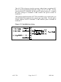
1
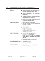
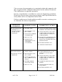
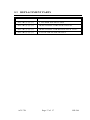
Model: ACC7B
PREAMPLIFIER / SIGNAL CONDITIONER
USER’S MANUAL
HP-244
August 2004
107 Kitty Hawk Lane, P.O. Box 2145, Elizabeth City, NC 27906-2145
800-628-4584 252-331-1997 FAX 252-331-2886
www.hofferflow.com E-mail: [email protected]
Notice
HOFFER FLOW CONTROLS, INC. MAKES NO WARRANTY OF
ANY KIND WITH REGARD TO THIS MATERIAL, INCLUDING, BUT
NOT LIMITED TO, THE IMPLIED WARRANTIES OF
MERCHANTABILITY AND FITNESS FOR A PARTICULAR
PURPOSE.
This manual has been provided as an aid in installing, connecting,
calibrating, operating, and servicing this unit. Every precaution for
accuracy has been taken in the preparation of this manual; however,
HOFFER FLOW CONTROLS, INC. neither assumes responsibility for
any omissions or errors that may appear nor assumes liability for any
damages that may result from the use of products in accordance with
information contained in the manual.
HOFFER FLOW CONTROLS’ policy is to provide a user manual for each
item supplied. Therefore, all applicable user manuals should be examined
before attempting to install or otherwise connect a number of related
subsystems.
During installation, care must be taken to select the correct interconnecting
wiring drawing. The choice of an incorrect connection drawing may result
in damage to the system and/or one of the components.
Please review the complete model of each item to be connected and locate
the appropriate manual(s) and/or drawing(s). Identify all model numbers
exactly before making any connections. A number of options and
accessories may be added to the main instrument, which are not shown on
the basic user wiring. Consult the appropriate option or accessory user
manual before connecting it to the system. In many cases, a system wiring
drawing is available and may be requested from HOFFER FLOW
CONTROLS.
This document contains proprietary information, which is protected by
copyright. All rights are reserved. No part of this document may be
photocopied, reproduced, or translated to another language without the
prior consent of HOFFER FLOW CONTROLS, INC.
HOFFER FLOW CONTROLS’ policy is to make running changes, not
model changes, whenever an improvement is possible. This affords our
customers the latest in technology and engineering. The information
contained in this document is subject to change without notice.
RETURN REQUESTS/INQUIRIES
Direct all warranty and repair requests/inquiries to the Hoffer Flow Controls Customer Service
Department, telephone number (252) 331-1997 or 1-800-628-4584. BEFORE RETURNING
ANY PRODUCT(S) TO HOFFER FLOW CONTROLS, PURCHASER MUST OBTAIN A
RETURNED MATERIAL AUTHORIZATION (RMS) NUMBER FROM HOFFER FLOW
CONTROLS’ CUSTOMER SERVICE DEPARTMENT (IN ORDER TO AVOID
PROCESSING DELAYS). The assigned RMA number should then be marked on the outside
of the return package and on any correspondence.
FOR WARRANTY RETURNS, please have
the following information available BEFORE
contacting HOFFER FLOW CONTROLS:
1. P.O. number under which the product
was PURCHASED,
2. Model and serial number of the product
under warranty, and
3. Repair instructions and/or specific
problems relative to the product.
HFC 9708
FOR NON-WARRANTY REPAIRS
OR CALIBRATIONS, consult
HOFFER FLOW CONTROLS for
current repair/calibration charges. Have
the following information available
BEFORE contacting HOFFER FLOW
CONTROLS:
1. P.O. number to cover the COST of
the repair/calibration,
2. Model and serial number of the
product, and
3. Repair instructions and/or specific
problems relative to the product.
LIMITED WARRANTY
HOFFER FLOW CONTROLS, INC. (“HFC”) warrants HFC’s products (“goods”) described in
the specifications incorporated in this manual to be free from defects in material and
workmanship under normal use and service, but only if such goods have been properly selected
for the service intended, properly installed and properly operated and maintained. This warranty
shall extend for a period of (1) year from the date of delivery to the original purchaser (or
eighteen (18) months if the delivery to the original purchaser occurred outside the continental
United States). This warranty is extended only to the original purchaser (“Purchaser”).
Purchaser’s sole and exclusive remedy is the repair and/or replacement of nonconforming goods
as provided in the following paragraphs.
In the event Purchaser believes the goods are defective, the goods must be returned to HFC,
transportation prepaid by Purchaser, within twelve (12) months after delivery of goods (or
eighteen (18) months for goods delivered outside the continental United States) for inspection
by HFC. If HFC’s inspection determines that the workmanship or materials are defective, the
goods will be either repaired or replaced, at HFC’s sole determination, free of additional charge,
and the goods will be returned, transportation paid by HFC, using the lowest cost transportation
available.
Prior to returning the goods to HFC, Purchaser must obtain a Returned Material Authorization
(RMA) Number from HFC’s Customer Service Department within 30 days after discovery of
a purported breach of warranty, but no later than the warranty period; otherwise, such claims
shall be deemed waived. See the Return Requests/Inquiries Section of this manual.
If HFC’s inspection reveals the goods are free of defects in material and workmanship or such
inspection reveals the goods were improperly used, improperly installed, and/or improperly
selected for service intended, HFC will notify the purchaser in writing and will deliver the goods
back to purchaser upon (i) receipt of Purchaser’s written instructions and (ii) the cost of
transportation. If Purchaser does not respond within 30 days after notice from HFC, the goods
will be disposed of in HFC’s discretion.
HFC does not warrant these goods to meet the requirements of any safety code of any state,
municipality, or any other jurisdiction, and purchaser assumes all risk and liability whatsoever
resulting from the use thereof, whether used singly or in combination with other machines or
apparatus.
This warranty shall not apply to any HFC goods or parts thereof, which have bee repaired
outside HFC’s factory or altered in any way, or have been subject to misuse, negligence, or
accident, or have not been operated in accordance with HFC’s printed instructions or have been
operated under conditions more severe than, or otherwise exceeding, those set forth in the
specifications for such goods.
THIS WARRANTY IS EXPRESSLY IN LIEU OF ALL OTHER WARRANTIES,
EXPRESSED OR IMPLIED, INCLUDING ANY IMPLIED WARRANTLY OF
MERCHANTABILITY OR FITNESS FOR A PARTICULAR PURPOSE. HFC SHALL
NOT BE LIABLE FOR ANY LOSS OR DAMAGE RESULTING, DIRECTLY OR
INDIRECTLY, FROM THE USE OF LOSS OF USE OF THE GOODS. WITHOUT
LIMITING THE GENERALITY OF THE FOREGOING, THIS EXCLUSION FROM
LIABILITY EMBRACES THE PURCHASER’S EXPENSES FOR DOWNTIME, DAMAGES
FOR WHICH THE PURCHASER MAY BE LIABLE TO OTHER PERSONS, DAMAGES TO
PROPERTY, AND INJURY TO OR DEATH OF ANY PERSON. HFC NEITHER ASSUMES
NOR AUTHORIZES ANY PERSON TO ASSUME FOR IT ANY OTHER LIABILITY IN
CONNECTION WITH THE SALE OR USE OF HFC’S GOODS, AND THERE ARE NO
AGREEMENTS OR WARRANTIES COLLATERAL TO OR AFFECTING THE
AGREEMENT. PURCHASER’S SOLE AND EXCLUSIVE REMEDY IS THE REPAIR AND/OR
REPLACEMENT OF NONCONFORMING GOODS AS PROVIDED IN THE PRECEDING
PARAGRAPHS. HFC SHALL NOT BE LIABLE FOR ANY OTHER DAMAGES WHATSOEVER
INCLUDING INDIRECT, INCIDENTAL, OR CONSEQUENTIAL DAMAGES.
Disclaimer:
Specifications are subject to change without notice.
Some pages are left intentionally blank.
HFC 9708
Table of Contents
Preface . . . . . . . . . . . . . . . . . . . . . . . . . . . . . . . . . . . . . . . . . . . . . . . . . . . i
1 Introduction . . . . . . . . . . . . . . . . . . . . . . . . . . . . . . . . . . . . . . . . . . . 1
1.1
Introduction . . . . . . . . . . . . . . . . . . . . . . . . . . . . . . . . . . . . . 1
1.2
Performance Characteristics . . . . . . . . . . . . . . . . . . . . . . . 2
1.3
Ordering Information . . . . . . . . . . . . . . . . . . . . . . . . . . . . . 3
1.4
Warranty . . . . . . . . . . . . . . . . . . . . . . . . . . . . . . . . . . . . . . . 4
1.5
Enclosure Detail . . . . . . . . . . . . . . . . . . . . . . . . . . . . . . . . . 5
1.6
Shipping and Handling . . . . . . . . . . . . . . . . . . . . . . . . . . . . 7
2 Installation . . . . . . . . . . . . . . . . . . . . . . . . . . . . . . . . . . . . . . . . . . . . 9
2.1
Installation Wiring Layout for Interconnections . . . . . . . . 9
2.2
Installation of the ACC7B . . . . . . . . . . . . . . . . . . . . . . . . . 9
3 Functional Description . . . . . . . . . . . . . . . . . . . . . . . . . . . . . . . . . . 11
3.1
Introduction . . . . . . . . . . . . . . . . . . . . . . . . . . . . . . . . . . . 11
3.2
Principle of Operation . . . . . . . . . . . . . . . . . . . . . . . . . . . 11
4 Calibration Procedure . . . . . . . . . . . . . . . . . . . . . . . . . . . . . . . . . . . 13
4.1
Introduction . . . . . . . . . . . . . . . . . . . . . . . . . . . . . . . . . . . 13
4.2
Required Test Equipment . . . . . . . . . . . . . . . . . . . . . . . . . 13
4.3
Controls and Adjustments . . . . . . . . . . . . . . . . . . . . . . . . 13
5 Maintenance . . . . . . . . . . . . . . . . . . . . . . . . . . . . . . . . . . . . . . . . . . 15
5.1
Introduction . . . . . . . . . . . . . . . . . . . . . . . . . . . . . . . . . . . 15
5.2
Trouble Shooting and Maintenance . . . . . . . . . . . . . . . . . 15
5.3
Replacement . . . . . . . . . . . . . . . . . . . . . . . . . . . . . . . . . . . 17
ACC-7B
HP-244
THIS PAGE LEFT INTENTIONALLY
ACC-7B
HP-244
PREFACE
This manual provides all the necessary information to correctly
install, operate, maintain and troubleshoot the Model ACC-7B
preamplifier interface.
The ACC-7B is intended to provide the user with a suitable pulse
interface between a frequency generating device and a data
acquisition system.
This manual is organized to provide ease of use. Individual
sections are provided to cover the Introduction, Installation,
Functional Description, Calibration, and Maintenance and
Troubleshooting. Illustrations have been used to improve the clarity
of information provided in this manual.
ACC-7B
i
HP-244
THIS PAGE LEFT INTENTIONALLY
ACC-7B
ii
HP-244
1
INTRODUCTION
1.1
INTRODUCTION
The Model ACC7B is a preamplifier with wave shaping that
allows convenient interfacing between the turbine flowmeter and
digital electronics.
The output signal has a square pulse wave form. Outputs are
provided to suit most users requirements. Summation of the
pulsing signal relates directly to the total flow throughput. The
frequency of the signal relates directly to the flow rate or the
velocity.
The input signal conditioning circuitry is designed to accept the
low level turbine flowmeter signal while providing rejection of
unwanted noise and spurious signals.
Two output signals are available. The first is a TTC/CMOS
compatible output. The second is an open collector of a medium
power transistor.
The unit is powered by a user supplied, filtered DC voltage. An
on board regulator provides the required regulation and noise
rejection.
ACC-7B
Page 1 of 17
HP-244
1.2
PERFORMANCE CHARACTERISTICS
INPUT
PULSE OUTPUT
!
Input protected, RF and band pass
filtered, adjustable trigger level.
!
Input Impedance 40 kilo ohm
(nominal).
!
Trigger Sensitivity 10 millivolt RMS
(minimum) 10 to 1000 Hz.
!
Input over voltage protected to 120
volts RMS absolute max.
!
Open Collector: Maximum
off state voltage 60 volts. Maximum
current 1.0 Amps.
!
TTL/CMOS:
Logic 0 = 0.0 volts.
Logic 1 = 5.0 volts.
Output capable of driving 6
standard TTL loads.
!
8 to 35 VDC unregulated or
5 VDC +/- 5% regulated.
Note: 12 to 35 VDC is required
when unit is equipped with pulse
opt. #5.
!
Required current: 15 mA max.
ENVIRONMENTAL
!
!
Operating 0-70 °C
Storage -20-70 °C
ENCLOSURES
!
General purpose case (standard),
NEMA- 4, Explosion Proof
INPUT POWER
ACC-7B
Page 2 of 17
HP-244
1.3
ORDERING INFORMATION
MODEL ACC7B-( A )-( B )-( C )
PULSE OUTPUT
INPUT POWER
ENCLOSURE STYLE
PULSE OUTPUT
MODEL ACC7B-( A )-(
OPTION ( A )
(1)
(2)
(3)
(5)
)-(
)
TTL/CMOS
OPEN COLLECTOR
OPEN COLLECTOR WITH PULL UP TO V+
0-10 V SQUARE WAVE (REQUIRED 12-35 VDC POWER)
INPUT POWER
MODEL ACC7B-( )-( B )-(
)
OPTION ( B )
(1)
UNREGULATED 8-35 VDC
(2)
REGULATED 5 VDC
ENCLOSURE STYLE
MODEL ACC7B-( )-(
)-( C )
OPTION ( C )
(1)
STYLE 1 CASE, GENERAL PURPOSE
(3H/O)
MEETS CLASS 1, DIV. 1 AND 2, GROUP D ONLY
CLASS II, GROUPS E, F, G
CLASS III
NEMA 4X WITH ‘O’ RING
CERTIFIED CSA, UL
BODY KILARK #GECCT-3, STOCK #200-0945
FLAT COVER, STOCK #200-0533, KILARK #GECBC.
(3BH/O)
MEETS CLASS I, DIV. 1 AND 2, GROUPS A, B, C, DCLASS 1, ZONES
1 AND 2, GROUPS IIB + H2, IIA
CLASS II, DIV. 1 AND 2, GROUPS E, F, G
CLASS III
NEMA 3, 4, 7 (B, C, D), 9 (E, F, G)
CERTIFIED CENELEC, CSA, UL, FM
BODY KILARK #HKB, STOCK #200-0406
DOME COVER, STOCK #200-0405, KILARK #HK2D.
NOTE:
INSERT (X) IN MODEL NUMBER FOR EVERY OPTION NOT SPECIFIED.
ACC-7B
Page 3 of 17
HP-244
1.4 WARRANTY
Hoffer Flow Controls warrants that all equipment will be free from
defects in workmanship and material provided that such equipment
was properly selected for the service intended, properly installed, and
not misused. Equipment which is returned transportation prepaid to
Hoffer Flow Controls within 12 months after delivery of goods, or 18
months from date of shipment on equipment for destination outside
the United States, and is found by Hoffer Flow Controls inspection to
be defective in workmanship or material, will be repaired or replaced
at Hoffer Flow Controls sole option, free of charge and returned
shipped using the lowest cost transportation prepaid.
In the event of product failure contact Hoffer Flow Controls at 252331-1997 or 800-628-4584, for issuance of a Returned Material
Authorization (RMA) number.
ACC-7B
Page 4 of 17
HP-244
1.5 ENCLOSURE DETAIL
The ACC7B may be packaged in either the General Purpose case
(Style 1), in an Explosion Proof case (Style 3), or in the NEMA 4
case (Style 5). Dimensions are given in Figures 1.2, 1.3, 1.4,
and 1.5.
Figure 1.2 General Purpose Case (Style1)
ACC-7B
Page 5 of 17
HP-244
Figure 1.3 Explosion Proof Case (Style 3)
Figure 1.4 NEMA 4 Case (Style 5)
ACC-7B
Page 6 of 17
HP-244
1.6
SHIPPING AND HANDLING
CAUTION - The ACC7B is a static-sensitive device and
standard practice for static sensitive parts
should be observed.
In the event of malfunctioning equipment the following
guidelines should be observed for the preparation and shipment of
the equipment. Failure to do so may result in the material reaching
its destination damaged.
The electronic unit due to its STATIC SENSITIVE nature should
be wrapped in a material conforming to MIL-B-81705 , Type II,
and packaged in a heat sealable bag conforming to MIL-P-81997.
These steps are necessary to protect the equipment from
electrostatic charge(s) that may occur during handling.
The package should then be marked with a sensitive electronic
device caution label conforming to MIL-STD-129, appendix C.
The equipment should then be wrapped in cushioning material, and
placed into a close fitting box conforming to PPP-B-636 Domestic
class.
The exterior shipping container should be marked with a sensitive
electronic device caution label conforming to
MIL-STD-129, Appen.C.
Clearly mark the factory provided RMA number on all paperwork
and shipping boxes.
ACC-7B
Page 7 of 17
HP-244
THIS PAGE LEFT INTENTIONALLY
ACC-7B
Page 8 of 17
HP-244
2
INSTALLATION
2.1
INSTALLATION WIRING
INTERCONNECTIONS
LAYOUT FOR
In considering the interconnections between the flowmeter and
the flow measurement system some attention must be given to
anticipated noise sources and to the coupling of these noise
sources to the interconnecting wiring.
Noise signals may be coupled inductively or capacitively into the
wiring between the flowmeter and the electronic measuring
systems. In general, utilizing a shielded, twisted pair for the
interconnection greatly reduces this coupling. The shield should
be grounded on one end of the cable only. In general, grounding
only on the electronic measuring system is best.
However, even with proper interconnecting cabling cross talk
with other signal lines or power lines may still occur and should
be avoided. Physical isolation of the wiring reduces the chance
of potential problems.
2.2
INSTALLATION OF THE ACC7B
The model ACC7B should be placed in a convenient location
which maintains access to the unit should repairs or readjustment
be required.
Refer to wiring installation Figure 2.1 for appropriate terminal
interconnections. Connection to the terminal block should be
carefully dressed to avoid having bare wires extending past the
screw clamp on the terminal block. This is particularly important
for units mounted within the explosion proof enclosure. Wires
should be neatly dressed near the bottom of the enclosure to
prevent problems when cover is installed.
Connect two conductor shielded signal cable from the flowmeter
to terminals 3 and 2. Connect the shield to terminal 2. Ground
the shield at one end only.
ACC-7B
Page 9 of 17
HP-244
The ACC7B is factory wired to operate either from a regulated 5V
DC or an unregulated but filtered voltage of 8 to 35V DC. Verify
correct power is available for the power option selected. Connect
the plus voltage to terminal 4 and connect the power return to
terminal 5.
The output signal from the ACC7B is available in several forms, see
model number designation for output type specified. For the pulse
output connect wire to terminal 1, and connect pulse common to
terminal 2.
Figure 2.1 Installation wiring
ACC-7B
Page 10 of 17
HP-244
3
FUNCTIONAL DESCRIPTION
3.1
INTRODUCTION
The ACC7B is a preamplifier which will provide a frequency pulse
output proportional to rate of flow. The unit is intended to provide
the user with a suitable interface between a flow measurement
sensor and a data acquisition system.
3.2
PRINCIPLE OF OPERATION
A block diagram showing functional blocks of the unit is depicted
in Figure 3.1. The principle of operation is as follows.
The electronics unit receives the signal form the flowmeter pickup
coil and converts it to a pulse output proportional to flow rate.
The electronics unit requires input power of 8 to 35 VDC (standard)
and 12 to 35 VDC when equipped with a 0 to 10 volt pulse output.
The frequency signal which is generated from the flowmeter is
connected to the ACC7B with a twisted shielded pair cable. The
signal enters the SENSITIVITY control which is used to reject
unwanted noise by raising the trigger threshold above the
background noise present.
The low level flowmeter signal is then passed through a signal
conditioning chain where it is filtered, amplified and shaped into
a train of digital pulses whose frequency is related to the volume
flow rate and where each pulse represents a discrete volume of
fluid.
The pulse train is then fed into the output stage which will generate
the required pulse output level desired.
ACC-7B
Page 11 of 17
HP-244
Figure 3.1 Block Diagram
ACC-7B
Page 12 of 17
HP-244
4
CALIBRATION PROCEDURE
4.1
INTRODUCTION
In general, all flow measurement systems supplied by Hoffer Flow
Controls have been factory tested and configured as specified by the
user, at the time of purchase, free of charge.
The ACC7B requires no field calibration.
4.2
REQUIRED TEST EQUIPMENT
In order to adjust the sensitivity and troubleshoot the ACC7B the
following suggested equipment list is provided:
4.3
MANUFACTURE
PART
NUMBER
DESCRIPTION
Fluke
8060A
True RMS Multimeter
Spectrol
8-T000
Adjustment Tool
CONTROLS AND ADJUSTMENTS
SENSITIVITY:
NOTE:
ACC-7B
A twenty turn control used to set the threshold
sensitivity level above the ambient noise
pickup.
IT IS NECESSARY TO OPEN THE COVER OF THE
ENCLOSURE BY REMOVING TWO SCREWS ON SIDE OF
BOX AND LIFTING COVER. TWO PRINTED CIRCUIT CARDS
ARE ATTACHED. THE "RANGE" DIP SWITCH MAY BE
PROGRAMMED WITH A PEN. INPUT POWER SHOULD BE
REMOVED DURING THIS STEP.
Page 13 of 17
HP-244
Figure 4.1 Control and Adjustment Detail
ACC-7B
Page 14 of 17
HP-244
5
MAINTENANCE
5.1 INTRODUCTION
Hoffer Flow Controls flow measurement systems are constructed to
give a long service life in the targeted measuring field and service
environment. However, problems do occur from time to time and the
following points should be considered for preventive maintenance
and repairs.
The bearing type used in the flowmeter was chosen to give
compromise between long life, chemical resistance, ease of
maintenance and performance. A preventive maintenance schedule
should be established to determine the amount of wear which has
occurred since last overhaul. See users manual for flowmeter for
further instructions.
A spare parts list has been provided which, at the discretion of the
user, may be user stocked. Consult with the manufacturer if an
abridged spare parts list is sought. The recommended spare parts list
may be found following this section and in the users manual for the
flowmeter.
In case the flow measurement system malfunctions or becomes
inoperative, a trouble shooting procedure follows.
Factory consultation is available to assist in diagnosing problems. In
addition, factory repair parts and service are available for individuals
who wish to utilize this service.
5.2 TROUBLE SHOOTING AND MAINTENANCE
!
!
ALL PRINTED CIRCUIT CARDS ARE WARRANTED FOR ONE YEAR
AFTER DATE OF SALE.
ALL PRINTED CIRCUIT CARDS MAY BE FACTORY REPAIRED AT A
NOMINAL FEE FOR PARTS AND LABOR AFTER WARRANTY
PERIOD.
In case of an inoperable or malfunctioning system the following
procedures can be used to isolate the faulty wiring, printed circuit
boards and/or alternate causes. The majority of repairs can be made
in the field thereby reducing the time a unit is out of service.
ACC-7B
Page 15 of 17
HP-244
The necessary documentation is contained within this manual with
the exception of the calibration data sheet for the turbine flowmeter.
This calibration is supplied separately.
Factory consultation is available to assist in diagnosing problems.
Please note that in some cases factory repairs can be performed more
easily than can be accomplished in the field.
Failure conditions are listed and the possible corrective actions given
to eliminate the observed problem.
OBSERVED
CONDITION
! UNIT DOES NOT
PRODUCE A
PULSE OUTPUT
WITH FLOW
PRESENT
POSSIBLE CAUSE
! POWER LOSS
! BAD PICKUP COIL
OR CABLE.
! STALLED TURBINE
FLOWMETER.
! BAD ACC7B
! SENSITIVITY
ADJUSTED FULLY
COUNTER
CLOCKWISE
CORRECTIVE ACTION
! CHECK INTERCONNECTING
WIRING AND HOST SYSTEM.
! CHECK PICKUP COIL AND
CABLE FOR CONTINUITY
AND LEAKAGE. REPLACE
AS REQUIRED.
! REMOVE FLOWMETER AND
REPAIR AS REQUIRED BY
MANUFACTURERS RECOM
MENDATIONS.
! REPAIR OR REPLACE
! ADJUST SENSITIVITY
! PULSE OUTPUT
! INPUT NOISE
! WITH NO FLOW
PRESENT
! BAD PICKUP COIL
OR CABLE
! TURN SENSITIVITY CCW
UNTIL FALSE OUTPUT
STOPS
! EXTREME SHOCK
OR VIBRATION OF
PIPING
! CHECK PICKUP COIL AND
CABLE FOR CONTINUITY
ANDLEAKAGE. REPLACE
AS REQUIRED.
! POWER SUPPLY
MALFUNCTION
! DAMPEN OR RELOCATE
PIPING
! BAD ACC7B
! CHECK AND REPAIR AS
REQUIRED
! REPAIR OR REPLACE
ACC-7B
Page 16 of 17
HP-244
5.3 REPLACEMENT PARTS
PART NUMBER
DESCRIPTION
ACC7B-(1)-(1)-(3)
TTL/CMOS PULSE OUTPUT
ACC7B-(2)-(1)-(3)
OPEN COLLECTOR PULSE OUTPUT
ACC7B-(3)-(1)-(3)
OPEN COLLECTOR WITH PULLUP TO V+
ACC7B-(5)-(1)-(3)
0 TO 10 VDC PULSE OUTPUT
ACC-7B
Page 17 of 17
HP-244