1
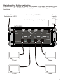
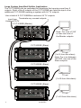
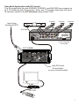
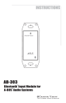
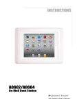
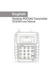
C-0333
CVT-2/8WB
2x8 Amplifier for Standard & Wide-Band
CATV Systems
10
The CVT-2/8WB and C-0333 are 8-output amplified splitters with a built-in
combiner for modulated signals. They allow IR signals to pass through the
modulator input to the TV outputs, making it a perfect match for the
E2200IR, E3200IR or E4200IR. The CVT-2/8WB is designed to mount
directly on any flat surface, while the C-0333 can snap directly into a
structured wiring enclosure.
Features:
! 8 Amplified outputs: 4.5dB Gain
! Amplified return path from 5-42MHz
! Compatible with Advanced Wide Bandwidth Digital CATV systems
! Supports 1 modulator input
! Allows IR pass through on the modulator input port
! Easy installation
C-0333
C-0333
Wide-Band Amplifier With Active Return Path
MOD IN
1
2
3
4
POWER IN
5
6
7
8
12 VDC
CABLE IN
+4.5 dB
TV OUTPUTS
MOD IN
Connect modulator here
CABLE IN...Connect the antenna
or cable service feed here
TV OUTPUTS
Connect TVs here
POWER IN
Connect power supply here
CVT-2/8WB
Cable In
+4.5dB
8
7
6
IR
Passing
4
3
2
TM
CHANNEL VISION
5
12VDC
1
MOD In
-15.5dB
CVT-2/8WB
Gain:
Forward Path (54-860MHz): +4.5dB, (975-1525MHz): Passive
Reverse Path (5-42MHz): Unity
Accessories Included:
Power Supply
12VDC, 500mA
2
CABLE IN...Connect the antenna
or cable service feed here
POWER IN
Connect power supply here
TV OUTPUTS
Connect TVs here
MOD IN
Connect modulator here
75 ohm Terminators
Basic Amplified Splitter Application
Connect the CVT-2/8WB as shown and locate it at the main distribution point
in the house. The CVT-2/8WB will supply the amplified TV signal to 8 TV
locations.
Input from
Antenna or CATV
Power
Supply
Connect up to 8 TVs
Terminate any unused outputs
CVT-2/8WB
Cable In
+4.5dB
8
7
6
IR
Passing
4
3
2
TM
CHANNEL VISION
5
12VDC
1
MOD In
-15.5dB
CVT-2/8WB
Gain:
Forward Path (54-860MHz): +4.5dB, (975-1525MHz): Passive
Reverse Path (5-42MHz): Unity
TV set
TV set
TV set
TV set
3
Large System Amplified Splitter Application
The CVT-2/8WB can be cascaded for situations that require more than 8
outputs. Each of the 8 outputs of the CVT-2/8WB can feed the input of an
additional CVT-2/8WB creating a system with 64 TV outputs.
Use a total of 9 CVT-2/8WBs to achieve 64 TV outputs.
Input from Terminate any unused outputs
Antenna/CATV
CVT-2/8WB (Master)
Cable In
+4.5dB
8
7
6
IR
Passing
4
3
2
TM
CHANNEL VISION
5
12VDC
1
MOD In
-15.5dB
CVT-2/8WB
Gain:
Forward Path (54-860MHz): +4.5dB, (975-1525MHz): Passive
Reverse Path (5-42MHz): Unity
TV set
Note: For runs of 150’
or less use one of
the Master outputs.
CVT-2/8WB (Slave)
Cable In
+4.5dB
8
7
6
IR
Passing
5
12VDC
4
3
2
1
MOD In
-15.5dB
TM
CHANNEL VISION
CVT-2/8WB
Gain:
Forward Path (54-860MHz): +4.5dB, (975-1525MHz): Passive
Reverse Path (5-42MHz): Unity
TV set
(1 of 8 from this slave)
Note: For runs between
150-250’ use one of the
Slave outputs.
CVT-2/8WB (Slave)
Cable In
+4.5dB
8
7
6
IR
Passing
4
3
2
TM
CHANNEL VISION
5
12VDC
1
MOD In
-15.5dB
CVT-2/8WB
Gain:
Forward Path (54-860MHz): +4.5dB, (975-1525MHz): Passive
Reverse Path (5-42MHz): Unity
TV set
(1 of 8 from this slave)
CVT-2/8WB (Slave)
Cable In
+4.5dB
8
7
6
IR
Passing
4
3
2
TM
CHANNEL VISION
5
12VDC
1
MOD In
-15.5dB
CVT-2/8WB
Gain:
Forward Path (54-860MHz): +4.5dB, (975-1525MHz): Passive
Reverse Path (5-42MHz): Unity
4
Power Supplies
not shown
TV set
(1 of 8 from this slave)
Cascaded Application with IR Control
The IR engine built into the E2200IR, E3200IR, and E4200IR can support up
to 8 TV locations with IR receivers. Note: any TV location that does not have
IR receiver needs to be DC blocked using model 3109.
Camera
Input from
Antenna/CATV
Camera
Camera
Sat Receiver
IR Emitter
CABLE
ANTENNA
D
B
12 3 4
OUTPUT
IR
C
A
L AUDIO R
RF OUT
VIDEO
L AUDIO R
VIDEO
ANTENNA + CABLE
OUTPUT
IR
1 2 3 4
DC 15V IN
E4200IR
Power Supplies
not shown
CVT-2/8WB
Fi
lte
r
Cable In
+4.5dB
8
7
6
IR
Passing
4
3
2
TM
CHANNEL VISION
5
12VDC
1
MOD In
-15.5dB
CVT-2/8WB
Gain:
Forward Path (54-860MHz): +4.5dB, (975-1525MHz): Passive
Reverse Path (5-42MHz): Unity
Use DC block
& terminator
on any unused output
TV set
4
1
0
8
5
2
9
6
3
IR-4101
7
F
Pow
er
R
5
Using the CVT-2/8WB with the Affinity (P-0321)
The CVT-2/8WB can be integrated with the P-0321 to send modulated signals
through a system that has some TVs with digital cable boxes and some TVs
without digital cable boxes. An RF filter can be used to remove the digital
content from the TVs which do not have digital boxes. This allows modulated
channels to be inserted without interference problems. The P-0321 preserves
the digital content for the locations that do have digital boxes. Additional details
regarding the operation of the Affinity model P-0321 can be found in its
installation manual.
Input from
Antenna/CATV
Camera
Camera
Camera
Sat Receiver
IN/out
5MHz-1GHz All Port DC passing
Part No. HS-2
2-WAY SPLITTER/COMBINER
IR Emitter
CABLE
ANTENNA
D
C HANNEL V ISION
OUT/in
TM
OUT/in
B
12 3 4
OUTPUT
IR
C
A
L AUDIO R
RF OUT
VIDEO
L AUDIO R
ANTENNA + CABLE
OUTPUT
IR
VIDEO
1 2 3 4
DC 15V IN
E4200IR
CVT-2/8WB
P-0321
RF
Filte
r
Cable In
+4.5dB
Pat. Pending
Power
PRO
Model
P-0321
CHANNEL
V ISION
TM
7
6
IR
Passing
4
3
2
TM
CHANNEL VISION
MOD Input
CATV Input
8
5
12VDC
1
MOD In
-15.5dB
CVT-2/8WB
Gain:
Forward Path (54-860MHz): +4.5dB, (975-1525MHz): Passive
Reverse Path (5-42MHz): Unity
IR Out
Output
tuo/NI
ni/TUO
NOISI V LENNAH C
gnissap CD troP llA zHG1-zHM5
MT
2-SH .oN traP
RENIBMOC/RETTILPS YAW-2
ni/TUO
Analog CATV
Location
Digital CATV
Location
3
2
6
1
8
TM
6
M
0
7
ula
od
er
w
Po
r
to
C
511
A0
V
AT
9
5
4
el
n
an n
h io
C Vis
Power Supplies
not shown
Specifications: (typical @25º C)
ITEM
MIN.
TYP.
MAX.
MODULATOR PATH
Operation Time
Full Time Bypass
Insertion Loss
<20dB (15dB typ.)
Return Loss (I/O)
>14dB
IR PASS
Yes
CATV FORWARD PATH
Frequency Range
54-860 / 975-1525MHz
6.0dB
Gain
54-800MHz
5.0dB
7.0dB
800-860MHz
5.0dB
4.0dB
6.0dB
-17dB
975-1525MHz
-20dB
-14dB
Flatness
+1.0dB
Return Loss (I/O)
>14dB
Isolation
>18dB
Noise Figure@70 degrees F
7.5dB
Group Delay (54 to 66MHz)
60ns
Group Delay (66 to 88MHz)
22ns
Group Delay (88 to 1000MHz)
12ns
Composite Second Order Distortions
64dBC
Composite Triple Beat Distortions
74dBC
60dBC
Cross Modulation Distortions
60dBC
Second Hum Modulation
+23.0 dBmV
Rated Output Level @160 channels, 6MHz each
180mA
Power Consumption
CATV RETURN PATH
Frequency Range
5-42MHz
0dB
5-40MHz
-1.0dB
1.0dB
40-42MHz
-1.0dB 0dB
-1.5dB
Flatness
+1.0dB
Return Loss (I/O)
>14dB
Isolation
>20dB
Noise Figure@70 degrees F
20dB
Group Delay (5 to 10MHz / 36MHz to 42MHz)
55ns
Group Delay (10 to 36MHz)
36ns
53dBC
Composite Second Order Distortions
56dBC
Composite Triple Beat Distortions
56dBC
Cross Modulation Distortions
58dBC
Second Hum Modulation
+43.0 dBmV
Rated Output Level @2 channels, 6MHz each
65mA
Power Consumption
GENERAL SPEC
RFI Shielding
>110dB
Nominal Impedance
“F” Female
75 ohm
Supply Voltage (DC)
12-15VDC
Specifications subject to change without notice.
7
1
Channel Vision Technology will repair or replace any defect in
material or workmanship which occurs during normal use of this
product with new or rebuilt parts, free of charge in the USA, for one
year from the date of original purchase. This is a no hassle warranty
with no mail in warranty card needed. This warranty does not cover
damages in shipment, failures caused by other products not supplied
by Channel Vision Technology, or failures due to accident, misuse,
abuse, or alteration of the equipment. This warranty is extended only
to the original purchaser, and a purchase receipt, invoice, or other
proof of original purchase date will be required before warranty
repairs are provided.
Mail in service can be obtained during the warranty period by calling
(800) 840-0288 toll free. A Return Authorization number must be
obtained in advance and can be marked on the outside of the shipping
carton.
This warranty gives you specific legal rights and you may have other
rights (which vary from state to state). If a problem with this product
develops during or after the warranty period, please contact Channel
Vision Technology, your dealer or any factory-authorized service
center.
Channel Vision products are not intended for use in medical,
lifesaving, life sustaining or critical environment applications.
Channel Vision customers using or selling Channel Vision products
for use in such applications do so at their own risk and agree to fully
indemnify Channel Vision for any damages resulting from such
improper use or sale.
www.channelvision.com
234 Fischer Avenue, Costa Mesa, California 92626 USA
(714)424-6500 (800)840-0288 (714)424-6510 fax
email: [email protected]
500-254 rev A1