1
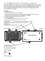
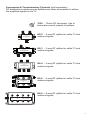
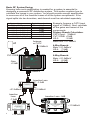
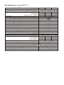
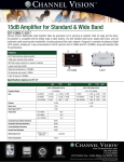
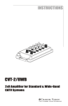
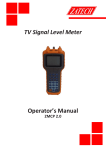
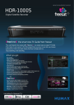
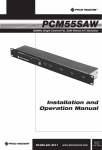
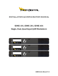
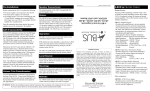
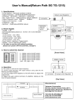
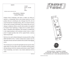
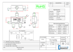
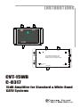
RF INPUT
DC12V
INPUT
C HANNEL V ISION
TM
CVT-15WB
CATV Forward Path (54-860MHz):+15dB
CATV Return Path (5-42MHz): Passive
WideBand CATV Path (975-1525MHz):Passive
OUT+POWER
DC 12V
INPUT
CABLE/ANT.
INPUT
RF INPUT
DC12V
INPUT
CATV FORWARD PATH (54-860MHz): +15dB
CCATV
HANNEL
V ISION
RETURN PATH (5-42MHz):
PASSIVE
TM
WIDEBAND CATV PATH (975-1525MHz): PASSIVE
CVT-15WB
CATV Forward Path (54-860MHz):+15dB
CATV Return Path (5-42MHz): Passive
WideBand CATV Path (975-1525MHz):Passive
OUT+POWER
CHANNEL VISION
TM
Central
OUT+POWER
C-0317
CVT-15WB
C-0317
15dB Amplifier for Standard & Wide-Band
CATV Systems
10
The CVT-15WB and C-0317 are 15dB Amplifiers for standard and
advanced digital CATV systems. The wide bandwidth design allows 2-way
communications in the RF spectrum from 975-1525MHz which is required
by some newer digital cable boxes. The CVT-15WB is idea for surface
mount applications while the C-0317 is designed to easily snap into a
structured wire enclosure.
Features:
!
15dB Amplifier
!
Passive return path from 5-42MHz
!
Compatible with Advanced Wide-Bandwidth Digital CATV systems
!
Built-in 6KV surge protection for superior durability
!
Phantom powered using model CVT-PI
!
Easy installation
!
CVT-15WB Dimensions: 4.70” x 4.35” x 1.06”
!
C-0317 Dimensions: 6.38” x 4.35” x 1.30”
CABLE IN
Connect the antenna or cable service feed here
POWER IN
Connect power supply here
CVT-15WB
C-0317
DC 12V
INPUT
RF INPUT
DC12V
INPUT
C HANNEL V ISION
CABLE/ANT.
INPUT
RF INPUT
DC12V
INPUT
CATV FORWARD PATH (54-860MHz): +15dB
CCATV
HANNEL
V ISION
RETURN PATH (5-42MHz):
PASSIVE
TM
TM
WIDEBAND CATV PATH (975-1525MHz): PASSIVE
CVT-15WB
CVT-15WB
CATV Forward Path (54-860MHz):+15dB
CATV Return Path (5-42MHz): Passive
WideBand CATV Path (975-1525MHz):Passive
CATV Forward Path (54-860MHz):+15dB
CATV Return Path (5-42MHz): Passive
WideBand CATV Path (975-1525MHz):Passive
OUT+POWER
OUT+POWER
CHANNEL VISION
TM
Central
TV OUTPUTS
Connect TVs here
Accessories Included:
Power Supply
12VDC, 500mA
2
OUT+POWER
C-0317
Accessories & Complementary Products (sold separately)
RF distribution systems require splitters and other accessories to deliver
the amplified signals to the TV.
2120 ... 75ohm RF terminator. Use to
!
terminate unused outputs of splitters.
!
!
!
!
!
HS-2 ... 2-way RF splitter for cable TV and
!
antenna signals.
!
OUT/in
OUT/in
C HANNEL V ISION
TM
Part No. HS-2
2-WAY SPLITTER/COMBINER
5MHz-1GHz All Port DC passing
IN/out
IN/out
C HANNEL V ISION
Part No. HS-3
3-WAY SPLITTER/COMBINER
TM
5MHz-1GHz All Ports DC passing
OUT/in
OUT/in
OUT/in
OUT/in
OUT/in
CHANNEL VISION
TM
Part No. HS-4
4-WAY SPLITTER/COMBINER
5MHz-1GHz All Port DC passing
OUT/in
IN/out
OUT
OUT
OUT
TM
IN
6-WAY SPLITTER 5MHz-1GHz
All ports DC passing
OUT
OUT
IN
C HANNEL V ISION
OUT
OUT
OUT
OUT
TM
HS-4 ... 4-way RF splitter for cable TV and
antenna signals.
OUT/in
C H A N N E L V I S I O N Part No. HS-6
OUT
HS-3 ... 3-way RF splitter for cable TV and
antenna signals.
HS-6 ... 6-way RF splitter for cable TV and
antenna signals.
OUT
OUT
HS-8 ... 8-way RF splitter for cable TV and
antenna signals.
Part No. HS-8
8-WAY SPLITTER 5MHz-1GHz
All ports DC passing
OUT
OUT
3
Basic RF System Design
Knowing how much amplification is needed for a system is essential to
designing a successful RF distribution system. This section explains how to
calculate the losses in your system. You should provide enough amplification
to overcome all of the insertion losses of all the system components. If the
signal splits into two branches, each branch must be calculated separately.
Typical Insertion Loss
~5.0dB
3.5dB
5.5dB
7.5dB
9.0dB
11.0dB
15.5dB
System Component
100ft. of RG6
HS-2 (2-way Splitter)
HS-3 (3-way Splitter)
HS-4 (4-way Splitter)
HS-6 (6-way Splitter)
HS-8 (8-way Splitter)
HS-16 (16-way Splitter)
Antenna
or CATV
+10dBmV
4-Way Branch:
Main: +21.5dBmV
HS-4: -7.5dB
+14.5dB
CVT-15WB
C HANNEL V ISION
Gain:
+15dB
6-Way Branch:
Main: +21.5dBmV
HS-6: -9.0dB
+11.5dB
RF INPUT
DC12V
INPUT
Example: Assume a CATV input
signal of 10dBmV. Next, calculate
all the gains and losses of the
components.
Primary Branch Calculation:
CATV Input: 10dBmV
CVT-15WB: +15dB
HS-2:
-3.5dB
Main total: +21.5dBmV
TM
CVT-15WB
CATV Forward Path (54-860MHz):+15dB
CATV Return Path (5-42MHz): Passive
WideBand CATV Path (975-1525MHz):Passive
OUT+POWER
+25dBmV
Insertion Loss:
-3.5dB
IN/out
5MHz-1GHz All Port DC passing
Part No. HS-2
2-WAY SPLITTER/COMBINER
C HANNEL V ISION
TM
OUT/in
+21.5dBmV
Insertion
Loss:
-7.5dB
Insertion Loss: -9dB
IN/out
OUT/in
OUT/in
5MHz-1GHz All Port DC passing
Part No. HS-4
4-WAY SPLITTER/COMBINER
CHANNEL VISION
OUT/in
TM
OUT/in
+14.5dBmV
OUT
OUT
OUT
C H A N N E L V I S I O N Part No. HS-6
TM
IN
4
OUT/in
+21.5dBmV
OUT
6-WAY SPLITTER 5MHz-1GHz
All ports DC passing
OUT
OUT
+11.5dBmV
Basic Amplified Splitter Application
Connect the CVT-15WB (or C-0317) as shown and locate it at the main
distribution point in the house. The CVT-15WB will supply the amplified TV
signal to the splitter which may be connected to several TV locations.
Power
Supply
Input from
Antenna or CATV
CVT-15WB
RF INPUT
DC12V
INPUT
C HANNEL V ISION
TM
CVT-15WB
CATV Forward Path (54-860MHz):+15dB
CATV Return Path (5-42MHz): Passive
WideBand CATV Path (975-1525MHz):Passive
OUT+POWER
IN/out
OUT/in
OUT/in
5MHz-1GHz All Port DC passing
Part No. HS-4
4-WAY SPLITTER/COMBINER
CHANNEL VISION
OUT/in
TM
OUT/in
TV set
TV set
TV set
TV set
5
Basic RF System Design
Knowing how much amplification is needed for a system is essential to
designing a successful RF distribution system. This section explains how to
calculate the losses in your system. You should provide enough amplification
to overcome all of the insertion losses of all the system components. If the
signal splits into two branches, each branch must be calculated separately.
Typical Insertion Loss
~5.0dB
3.5dB
5.5dB
7.5dB
9.0dB
11.0dB
15.5dB
System Component
100ft. of RG6
HS-2 (2-way Splitter)
HS-3 (3-way Splitter)
HS-4 (4-way Splitter)
HS-6 (6-way Splitter)
HS-8 (8-way Splitter)
HS-16 (16-way Splitter)
Antenna
or CATV
+10dBmV
4-Way Branch:
Main: +21.5dBmV
HS-4: -7.5dB
+14.5dB
CVT-15WB
6-Way Branch:
Main: +21.5dBmV
HS-6: -9.0dB
+11.5dB
RF INPUT
DC12V
INPUT
C HANNEL V ISION
Example: Assume a CATV input
signal of 10dBmV. Next, calculate
all the gains and losses of the
components.
Primary Branch Calculation:
CATV Input: 10dBmV
CVT-15WB: +15dB
HS-2:
-3.5dB
Main total: +21.5dBmV
TM
CVT-15WB
CATV Forward Path (54-860MHz):+15dB
CATV Return Path (5-42MHz): Passive
WideBand CATV Path (975-1525MHz):Passive
OUT+POWER
+25dBmV
IN/out
5MHz-1GHz All Port DC passing
Part No. HS-2
2-WAY SPLITTER/COMBINER
C HANNEL V ISION
TM
OUT/in
+21.5dBmV
IN/out
OUT/in
OUT/in
5MHz-1GHz All Port DC passing
Part No. HS-4
4-WAY SPLITTER/COMBINER
CHANNEL VISION
OUT/in
TM
OUT/in
+14.5dBmV
OUT
OUT
OUT
C H A N N E L V I S I O N Part No. HS-6
TM
IN
6
OUT/in
+21.5dBmV
OUT
6-WAY SPLITTER 5MHz-1GHz
All ports DC passing
OUT
OUT
+11.5dBmV
Specifications: (typical @25º C)
ITEM
MIN.
TYP.
MAX.
CATV FORWARD PATH
54-1525MHz
+15.0dB +16.0dB
Gain
54-60MHz +14.0dB
60-860MHz +14.0dB
+15.5dB +16.0dB
(Passive) 975-1525MHz
-2.5dB
-4.0dB
-1.5dB
Flatness
+1.0dB
Return Loss (I/O)
>15dB
Noise Figure@70 degrees F
3.0dB
Group Delay (54 to 66MHz)
60ns
Group Delay (66 to 88MHz)
22ns
Group Delay (88 to 1000MHz)
12ns
Composite Second Order Distortions
60dBC
Composite Triple Beat Distortions
60dBC
60dBC
Cross Modulation Distortions
70dBC
Second Hum Modulation
+23.0dBmV
Rated Output Level @160 channels, 6MHz each
150mA
Power Consumption
CATV RETURN PATH
5-42 + 975-1525MHz
5-42MHz
-3.0dB
-1.0dB
-2.0dB
975-1000MHz
-4.0dB
-3.0dB
-5.0dB
1000-1525MHz
-2.5dB
-1.5dB
-3.5dB
+1.0dB
>15dB
Frequency Range
Flatness
Return Loss (I/O)
GENERAL SPEC
RFI Shielding
Nominal Impedance
Supply Voltage (DC)
“F” Female
>110dB
75 ohm
12-15VDC
Specifications subject to change without notice.
7
1
Channel Vision Technology will repair or replace any defect in
material or workmanship which occurs during normal use of this
product with new or rebuilt parts, free of charge in the USA, for one
year from the date of original purchase. This is a no hassle warranty
with no mail in warranty card needed. This warranty does not cover
damages in shipment, failures caused by other products not supplied
by Channel Vision Technology, or failures due to accident, misuse,
abuse, or alteration of the equipment. This warranty is extended only
to the original purchaser, and a purchase receipt, invoice, or other
proof of original purchase date will be required before warranty
repairs are provided.
Mail in service can be obtained during the warranty period by calling
(800) 840-0288 toll free. A Return Authorization number must be
obtained in advance and can be marked on the outside of the shipping
carton.
This warranty gives you specific legal rights and you may have other
rights (which vary from state to state). If a problem with this product
develops during or after the warranty period, please contact Channel
Vision Technology, your dealer or any factory-authorized service
center.
Channel Vision products are not intended for use in medical,
lifesaving, life sustaining or critical environment applications.
Channel Vision customers using or selling Channel Vision products
for use in such applications do so at their own risk and agree to fully
indemnify Channel Vision for any damages resulting from such
improper use or sale.
www.channelvision.com
234 Fischer Avenue, Costa Mesa, California 92626 USA
(714)424-6500 (800)840-0288 (714)424-6510 fax
email: [email protected]
500-253 rev B1