1
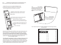
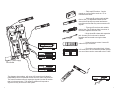
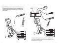
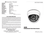
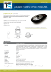
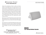
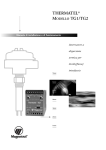
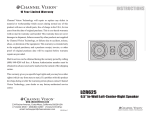
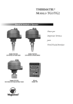
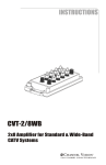
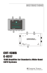
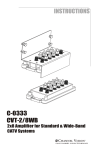
Specifications: (typical)
Power Supply Voltage:
IR Frequency range supported:
Maximum number of targets:
Maximum distance to emitters:
CHANNEL
V ISION
12 VDC
30 kHz - 56 kHz
16
500 ft.
TM
P-1205
Specifications subject to change without notice.
IR distribution hub
CHANNEL VISION
Limited Warranty
Channel Vision Technology will repair or replace any defect in
material or workmanship which occurs during normal use of this
product with new or rebuilt parts, free of charge in the USA, for two
years from the date of original purchase. This is a no hassle warranty
with no mail in warranty card needed. This warranty does not cover
damages in shipment, failures caused by other products not supplied
by Channel Vision Technology, or failures due to accident, misuse,
abuse, or alteration of the equipment. This warranty is extended only
to the original purchaser, and a purchase receipt, invoice, or other
proof of original purchase date will be required before warranty
repairs are provided.
n
Expansio
bal Zone
Pwr Glo
eiver
IR Rec
Model
P-1205
NEL
CHAN
V I S IO N
TM
Global
IR
r
Receive
s
Emitter
+12DC
Zone
Mail in service can be obtained during the warranty period by calling
(800) 840-0288 toll free. A Return Authorization number must be
obtained in advance and can be marked on the outside of the shipping
carton.
This warranty gives you specific legal rights and you may have other
rights (which vary from state to state). If a problem with this product
develops during or after the warranty period, please contact Channel
Vision Technology, your dealer or any factory-authorized service
center.
500-073 rev E
C HANNEL V ISION
TM
234 Fischer Avenue · Costa Mesa, CA 92626
(714) 424-6500 · (800) 840-0288 · (714) 424-6510 fax
www.channelvision.com · email: sales @ channelvision.com
© 2004 Channel Vision Technology
The P-1205 distribution hub supplies power to any standard IR receiver
and IR signals to 4 emitter outputs (2 global, and 2 zone specific).
!
!
!
Multiple IR zones can be created with additional units
Single power supply can support up to 16 IR receivers
Both mini plug and 3-wire connection for receivers
Mounting Options
The NEW P-1300 from Channel
Vision’s Pro-series product line is
the perfect home for the P-1205.
The P-1300 is a hinged plate
designed to fit into a standard 19”
rack.
Expansion connectors are used to hook up
additional units and create more IR zones.
Status LEDs.
n
Expansio
Expansio
bal Zone
Pwr Glo
Pwr
n
Zone
Global
eiver
IR Rec
l
Mode
P-1205
eiver
IR Rec
NN
Model
P-1205
NEL
CHAN
V I S IO N
The P-1300 hinges open to
maintain a clean look and
provide easy access for
servicing equipment.
EL
TM
al
Glob
IR
r
Receive
Emitters
IR receivers can be connected using either
the 3-wire terminals or mini-plug.
CHA
N
V I S IO
Zone
C
+12D
TM
Global IR emitters will flash when any
IR receiver in the system detects a signal.
Global
IR
r
Receive
s
Emitter
+12DC
Zone
Zone IR emitters will only flash when an
IR receiver the same P-1205 detects a
signal.
Power connection.
2
Zone
Global
+12DC
Emitters
IR
Receiver
TM
Model
P-1205
+V
CHANNEL
V ISION
Expansion
Sig
IR repeating concepts:
Most people are familiar with Infra-Red remote controls because they use
them to operate their TV and other devices on a daily basis. However,
some people may not be familiar with IR repeating. IR repeating allows
the user to control devices which are not within the direct line of sight of
the remote control. This is most commonly used in distributed audio/video
systems where the source components are centrally located. See How IR
repeating works on the next page for details.
IR zones:
Some IR systems, including the P-1205, are capable of creating zones that
only repeat the IR signals that are picked up by a particular receiver (or
group of receivers). This is useful when there are multiple devices from
the same manufacturer, such as satellite decoders, that are operated with
the same remote control. IR zones prevent one user from inadvertently
control a satellite decoder that someone else is trying to watch.
Pwr Global Zone
The P-1205 can also be mounted in a standard structured wiring enclosure
as shown below.
IR Receiver
7
Other IR components
Zoned IR Setup
IR-2301 ... Table top IR Receiver. Can be
placed on any flat surface such as a TV or
entertainment center.
Zone A
(Bedroom 1)
IR-2105 ... Stick type IR receiver with variable
field of view. An adjustable blinder swivels
around the IR pickup to prevent interference
from light sources that may cause erroneous IR
signals.
Zone B
(Bedroom 2)
IR-2202 ... Tube type IR receiver with variable
field of view. The IR pickup slides in and out of
the tube to adjust the field of view.
Expansion
Expansion
IR-3003... Single head IR emitter with expansion
jack. As many as 3 units can be chained
together and connected to a single emitter
output.
bal Zone
Pwr Glo
ceiver
IR Re
ceiver
IR Re
bal Zone
Pwr Glo
Model
P-1205
Model
P-1205
NEL
CHAN
V I S IO N
TM
NEL
CHAN
I S IO N
Global device
TM
Stop
Play>
Pause
FF>>
Receiver
Tx Batt
3
Rew<<
9
6
Learn
2
Vol
-/--
1
0
8
5
Ch
7
4
Power
Off
Sat
All Off
TV
Learn Error
CD
TM
DVD
+12DC
Channel Vision
rs
Emitte
+12DC
VCR
rs
Emitte
Global
IR
Receiver
Tuner
AB-500
Global
IR
Receiver
Select
V
AB500 ... Universal remote control. Learns IR
codes for up to 6 sources.
C-1201 ... IR receiver connecting block. Allows
8 IR receivers to be connected in parallel so that
one set of wires can be connected to the P-1205
Zone
Zone
C HANNEL V ISION
Sat radio
TM
C-1201
Central
DVD player
Zone B devices
Only 1 power supply
is needed.
How IR repeating works
Sat radio
The IR receiver is wired to
the IR hub which routes the
signal to IR emitters
DVD player
Re
Zone A devices
Pl
n
tt
ar
Ba
Le
<<
Tx
w
ay
>
St
FF
op
1
>>
e
2
us
Pa
4
7
3
er
w
Po
5
8
6
0
9
-/-
Ch
-
Vo
l
le
Le
ct
ar
r
Er
ne
n
Tu
ro
r
Al
VC
ff
lO
R
CD
ff
O
D
C
DV
Sa
-5
0
n
io
Vis 0
AB
el
TV
n
an
t
h
TM
6
Se
The diagram shown above, will create 2 IR zones that will allow for
independent control of identical devices from the same manufacturer.
The zone IR emitters will only respond to signals from the IR receiver
that is in the same zone. The global IR emitters will respond to
signals from any IR receiver in the system.
Point any
IR remote control
at the IR receiver
CD player
And the emitter
repeats the IR signal
in the other room.
Be sure the emitter is attached directly
over the component’s IR receiver.
3
Basic IR Setup
Whole-House IR Setup
A basic IR system, like the one shown below, is often used when
audio/video devices are stored inside a closed cabinet and are out of
the line of sight. The IR receiver is placed outside the cabinet so that
the remote control can be point directly at it. It will detect the IR
signals and route to the P-1205, which in turn sends them to the
emitter outputs.
Additional IR receivers
can be connected as
needed.
Bedroom 3
C HANNEL V ISION
Bedroom 2
TM
C-1201
Central
Bedroom 1
ttaB xT
>>FF
>yalP
esuaP
<< we R
potS
3
nraeL
2
6
5
9
8
1
Expansion
4
7
--/-
n
0
Expansio
loV
Tx
r ew oP
Rew
Lear
Batt
<<
Play
bal Zone
Pwr Glo
hC
>
n
FF>
>
Stop
Pau
se
1
2
rorrE n
raeL
bal Zone
Pwr Glo
ff O
tceleS
taS
VT
eiver
IR Rec
Model
P-1205
MT
DC
renuT
DV D
noisiV
len
R CV
nahC
005-BA
ceiver
IR Re
ff O llA
3
4
Model
P-1205
5
6
7
8
Pow
er
9
0
-/--
Ch
Vol
NEL
Lear
CHAN
V I S IO N
Sele
All
ct
Tun
er
TM
n Erro
r
Off
Off
CD
VCR
Sat
DVD
TV
Ch
an
nel
AB Vision
-500
TM
NEL
CHAN
V I S IO N
TM
Global
IR
Receiver
rs
Emitte
Global
IR
r
Receive
+12DC
Emitter
Sat radio
DVD player
s
+12DC
Zone
Zone
Sat radio
DVD player
CD player
CD player
Receiver
Receiver
4
The diagram above illustrates how to create an IR system with IR
receivers in several different rooms in the house. Systems like this
may include several different styles of IR receivers depending on the
specific application in each room.
5