1
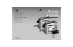
Zebra
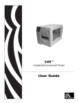
170PAX2 ™ -Series
User ’s Guide
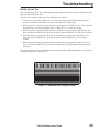
RIGHT HAND
LEFT HAND
R
Proprietary Statement
This manual contains proprietary information of Zebra Technologies Corporation. It is intended solely for the
information and use of parties operating and maintaining the equipment described herein. Such
proprietary information may not be used, reproduced, or disclosed to third parties for any other purpose
without the expressed written permission of Zebra Technologies Corporation.
Product Improvements
Continuous improvement of products is a policy of Zebra Technologies Corporation. All specifications and signs
are subject to change without notice.
FCC Compliance Statement
This equipment has been tested and found to comply with the limits for a Class A digital Device, pursuant to Part 15
of the FCC Rules. These limits are designed to provide reasonable protection against harmful interference when
the equipment is operated in a commercial environment. This equipment generates, uses and can radiate radio
frequency energy and, if not installed and used in accordance with the instructions manual, may cause harmful
interference to radio communications. Operation of this equipment in a residential area is likely to cause
harmful interference in which case the user will be required to correct the interference at his own expense.
In order to insure compliance, this printer must be used with a Shielded Power Cord and Shielded Communication
Cables.
“The user is cautioned that any changes or modifications not expressly approved by Zebra Technologies Corporation
could void the user’s authority to operate the equipment.”
Canadian DOC Compliance Statement
This digital apparatus does not exceed the Class A limits for radio noise emissions from digital apparatus as set out in
the radio interference regulations of the Canadian Department of Communications.
Liability Disclaimer
Zebra Technologies Corporation takes steps to assure that its published Engineering Specifications and Manuals are
correct; however, errors do occur. Zebra Technologies Corporation reserves the right to correct any such errors and
disclaims liability resulting therefrom.
No Liability for Consequential Damage
In no event shall Zebra Technologies Corporation or anyone else involved in the creation, production, or delivery
of the accompanying product (including hardware and software) be liable for any damages whatsoever (including,
without limitation, damages for loss of business profits, business interruption, loss of business information, or
other pecuniary loss) arising out of the use of or the results of use of or inability to use such product, even if Zebra
Technologies Corporation has been advised of the possibility of such damages. Because some states do not allow
the exclusion or limitation of liability for consequential or incidental damages, the above limitation may not apply
to you.
Copyrights
The copyrights in this manual and the label printer described therein are owned by Zebra Technologies
Corporation. All rights are reserved. Unauthorized reproduction of this manual or the software in the label printer
may result in imprisonment of up to one year and fines of up to $10,000 (17 U.S.C.506). Copyright violators may be
subject to civil liability.
Zebra 170PAX™, 174PAX™, 175PAX™, ZebraNet™, ProPlus™, Platinum™, and Z-Tools™ are trademarks and
ZPL®, ZPL II®, and BAR-ONE® are registered trademarks of Zebra Technologies Corporation.
Centronics® is a registered trademark of Genicom Corporation.
IBM® is a registered trademark of IBM Corporation.
© 1999 Zebra Technologies Corporation. All rights reserved.
Contents
Introduction
Zebra 170PAX2 Print Engine
Getting Started . . . . . . .
Print Engine Mounting . . .
Communications . . . . . .
Printer Power . . . . . . . .
.
.
.
.
.
.
.
.
.
.
.
.
.
.
.
.
.
.
.
.
.
.
.
.
.
.
.
.
.
.
.
.
.
.
.
.
.
.
.
.
.
.
.
.
.
.
.
.
.
.
.
.
.
.
.
.
.
.
.
.
.
.
.
.
.
.
.
.
.
.
.
.
.
.
.
.
.
.
.
.
.
.
.
.
.
.
.
.
.
.
.
.
.
.
.
.
.
.
.
.
.
.
.
.
.
.
.
.
.
.
1
1
1
1
2
Media & Ribbon Loading
Media Loading . . . . . . . . . . . . . . . . . . . . . . . . . . . . . 3
Ribbon Loading . . . . . . . . . . . . . . . . . . . . . . . . . . . . . 5
Removing Used Ribbon . . . . . . . . . . . . . . . . . . . . . . . . 6
Media Sensor Position
Reflective Media Sensor . . . . . . . . . . . . . . . . . . . . . . . . 7
Transmissive Media Sensor. . . . . . . . . . . . . . . . . . . . . . . 7
Printer Operation
Power On/Off Switch . . . . . . . . . . . . . . . . . . . . . . . . . . 9
Front Panel Keys . . . . . . . . . . . . . . . . . . . . . . . . . . . . 9
Liquid Crystal Display . . . . . . . . . . . . . . . . . . . . . . . . 10
Control Panel Keys . . . . . . . . . . . . . . . . . . . . . . . . . . 10
Front Panel Indicator Lights (LEDs) . . . . . . . . . . . . . . . . . 10
Configuration and Calibration
Introduction . . . . . . . . . . . . . . . .
Configuration Process . . . . . . . . . . .
Setting Print Parameters . . . . . . . . . .
Listing Printer Information . . . . . . . .
Media and Ribbon Sensor Calibration . .
Setting Communication Parameters . . . .
Selecting Prefix and Delimiter Characters
Selecting ZPL Mode . . . . . . . . . . . .
Setting Ribbon Tension . . . . . . . . . .
Power Up and Head Close Parameters . .
Label Positioning Parameters . . . . . . .
Head Test Function . . . . . . . . . . . .
Head Resistance . . . . . . . . . . . . . .
Verifier Port . . . . . . . . . . . . . . . .
Applicator Port . . . . . . . . . . . . . .
Printing Controls . . . . . . . . . . . . .
Sensor Values . . . . . . . . . . . . . . .
LCD Adjust . . . . . . . . . . . . . . . .
Printer Language . . . . . . . . . . . . .
170PAX2-Series User’s Guide
.
.
.
.
.
.
.
.
.
.
.
.
.
.
.
.
.
.
.
.
.
.
.
.
.
.
.
.
.
.
.
.
.
.
.
.
.
.
.
.
.
.
.
.
.
.
.
.
.
.
.
.
.
.
.
.
.
.
.
.
.
.
.
.
.
.
.
.
.
.
.
.
.
.
.
.
.
.
.
.
.
.
.
.
.
.
.
.
.
.
.
.
.
.
.
.
.
.
.
.
.
.
.
.
.
.
.
.
.
.
.
.
.
.
.
.
.
.
.
.
.
.
.
.
.
.
.
.
.
.
.
.
.
.
.
.
.
.
.
.
.
.
.
.
.
.
.
.
.
.
.
.
.
.
.
.
.
.
.
.
.
.
.
.
.
.
.
.
.
.
.
.
.
.
.
.
.
.
.
.
.
.
.
.
.
.
.
.
.
.
.
.
.
.
.
.
.
.
.
.
.
.
.
.
.
.
.
.
.
.
.
.
.
.
.
.
.
.
.
.
.
.
.
.
.
.
.
.
.
.
.
.
.
.
.
.
.
.
.
.
.
.
.
.
.
.
.
.
.
.
.
.
.
.
.
.
.
.
.
.
.
.
.
.
.
.
11
12
12
16
18
20
23
24
24
24
25
28
28
28
29
30
31
32
32
i
Contents
Care & Adjustments
Cleaning . . . . . . . . . . . . . . . . . . . . . . . . . . . . . . . . 33
Toggle Positioning. . . . . . . . . . . . . . . . . . . . . . . . . . . 35
Printhead Pressure Adjustment . . . . . . . . . . . . . . . . . . . . 35
Troubleshooting
Power On Self Test . . . .
Power On Troubleshooting
Printer Troubleshooting . .
Printer Self Tests. . . . . .
.
.
.
.
.
.
.
.
.
.
.
.
.
.
.
.
.
.
.
.
.
.
.
.
.
.
.
.
.
.
.
.
.
.
.
.
.
.
.
.
.
.
.
.
.
.
.
.
.
.
.
.
.
.
.
.
.
.
.
.
.
.
.
.
.
.
.
.
.
.
.
.
.
.
.
.
.
.
.
.
.
.
.
.
.
.
.
.
37
38
38
42
Options
Single In-line Memory Module (SIMM) . . . . . . .
Personal Computer Memory Card Interface Association
(PCMCIA) Memory Card . . . . . . . . . . . . . . .
Communication Interfaces. . . . . . . . . . . . . . . .
ZebraNet™ Micro Print Server (MPS) . . . . . . . .
. . . . . . . 47
. . . . . . . 47
. . . . . . . 47
. . . . . . . 47
Printer Specifications
Appendix A
AC Power Cord Requirements . . . . . . . . . . . . . . . . . . . . 53
Power Fuse Replacement . . . . . . . . . . . . . . . . . . . . . . . 53
Shipping . . . . . . . . . . . . . . . . . . . . . . . . . . . . . . . . 54
Appendix B
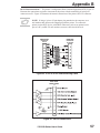
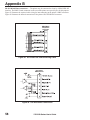
Printer Communications Interface Technical Information
RS-232/RS-422/RS-485 Serial Data Port . . . . . . . . .
Centronics-Compatible Parallel Data Port . . . . . . . .
Cabling Requirements . . . . . . . . . . . . . . . . . . .
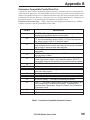
Applicator Interface Connector . . . . . . . . . . . . . .
.
.
.
.
.
.
.
.
.
.
.
.
.
.
.
.
.
.
.
.
.
.
.
.
.
.
.
.
.
.
55
56
59
60
60
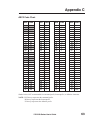
Appendix C
ASCII Code Chart . . . . . . . . . . . . . . . . . . . . . . . . . . . 63
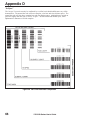
Appendix D
Adjusting Darkness For “In-Spec” Bar Codes . . . . . . . . . . . . 65
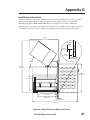
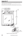
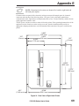
Appendix E
Installation Information . . . . . . . . . . . . . . . . . . . . . . . . 67
Glossary
Index
ii
170PAX2-Series User’s Guide
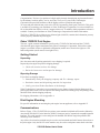
Introduction
Congratulations! You have just purchased a high-quality thermal demand print engine manufactured
by the industry leader in quality, service, and value. For over 25 years, Zebra Technologies
Corporation has provided customers with the highest caliber of products and support.
To create and print label formats, refer to the ZPL II Programming Guide (part # 46530L). This guide
is available by contacting your distributor or Zebra Technologies Corporation. It is also available as a
file to download from Zebra’s web site “support.zebra.com”. In addition, label preparation software is
available. Contact your distributor or Zebra Technologies Corporation for further information.
The Zebra 170PAX™-Series Maintenance Manual (part # 49803L) contains the information you may
need to properly maintain the print engine.
Zebra 170PAX2 Print Engine
This user’s guide contains information specific to the 172PAX2 (203 dot/inch) and the 173PAX2
(300 dot/inch) print engines manufactured by Zebra Technologies Corporation. Each of these print
engines is available in either a right hand configuration (media moves from left to right) or a left
hand configuration (media moves from right to left.)
Getting Started
Unpacking
Save the carton and all packing materials in case shipping is required.
Inspect the print engine for possible shipping damage:
•
Check all exterior surfaces for damage.
•
Raise the front cover and inspect for damage.
Reporting Damage
If you discover shipping damage:
•
Immediately notify the shipping company and file a damage report.
•
Retain the carton and all packing material for inspection.
•
Notify your local Zebra distributor of the damage.
Zebra Technologies Corporation is not responsible for any damage incurred during shipment of the
print engine and will not cover the repair of this damage under its warranty policy. Any damage claim
should be filed with the shipping company.
For shipping information, refer to Appendix A.
Print Engine Mounting
For specific information on mounting the print engine into an applicator, refer to Appendix E.
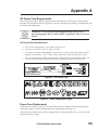
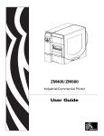
Communications
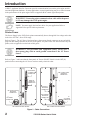
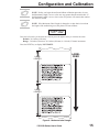
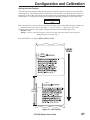
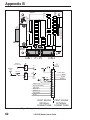
Refer to Figure 1. The 170PAX2™-Series printer comes standard with both an Electronics Industries
Association (EIA) RS-232 serial interface (DB-25 Connector) and a Centronics®-compatible parallel
interface. The serial interface is also configured for both RS-422/RS-485 single drop and RS-485
multi-drop serial interfaces.
Any of these four interface methods may be used to send commands and label formats from a host to
the print engine. Only the RS-232 serial interface may be used to send printer status back to the host.
170PAX2-Series User’s Guide
1
Introduction
A DB-15 Applicator Interface Connector provides communication between the print engine and the
associated applicator hardware. In some applications, control signal timing may be a critical element
in the performance of the print engine. Refer to Appendix B for control signal descriptions.
WARNING!! Connecting a data communications cable while the power
is ON may damage the PAX2 print engine.
NOTE: You must supply the interface cables for your application. Refer to
Appendix B for specific cable requirements.
Printer Power
The Power Supply in the PAX2-Series printer automatically detects the applied line voltage and works
in the 90 to 264 VAC, 48 to 62 Hz range.
Refer to Figure 1. The AC Power Cord must have a three-prong female connector on one end which
plugs into the mating connector at the rear of the printer. If a power cable was not included with your
printer, refer to Appendix A at the back of this guide.
WARNING!! For personnel and equipment safety, always use a
three-prong plug with an earth ground connection to the AC Power
Source.
Refer to Figure 7 and insure that the front panel AC Power ON/OFF Switch is in the OFF (O)
position before connecting the AC Power cord to a nearby electrical outlet.
DB-25 SERIAL
INTERFACE
CONNECTOR
DB-15 APPLICATOR
INTERFACE
CONNECTOR
PARALLEL
INTERFACE
CONNECTOR
PARALLEL
INTERFACE
CONNECTOR
DB-15 APPLICATOR
INTERFACE
CONNECTOR
DB-25 SERIAL
INTERFACE
CONNECTOR
AC POWER
CONNECTOR
LEFT HAND PAX PRINT ENGINE
RIGHT HAND PAX PRINT ENGINE
Figure 1. Cable Connections
2
AC POWER
CONNECTOR
170PAX2-Series User’s Guide
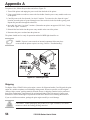
Media & Ribbon Loading
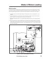
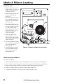
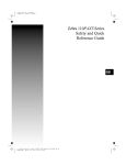
Media Loading
If your print engine is a right hand unit (printed labels are presented on the right hand side of the
unit), refer to Figure 2 while performing the procedure shown below. If your print engine is a left
hand configuration (printed labels are presented on the left hand side of the unit), refer to Figure 3.
1. Load the media on the media supply hanger of the applicator (refer to the applicator’s user’s
manual).
2. Grasp the thumb nut (A) and slide the outer media edge guide (B) as far out from the printer
frame as possible. (The thumb nut does not have to be loosened.)
3. Open the printhead assembly (C) by unlatching the printhead lock lever (D) from the locking
pin (E).
4. Raise the pinch roller (F) by pressing down on the pinch roller assembly latch (G). Thread the
media under the upper guide post (H), between the pinch roller and the associated rubber pinch
roller, and under the printhead assembly (C) until approximately 30" (75 cm) of media extends
out of the print engine.
DETAIL
K
L
J
OPEN
OPEN
D
G
H
E
C
MEDIA
PATH
MEDIA
BACKING
M
F
B
A
I
SEE DETAIL
LABEL
Figure 2. Media Loading (Right-Hand Units)
170PAX2-Series User’s Guide
3
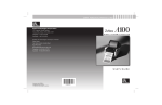
Media & Ribbon Loading
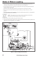
5. Ensure the media is aligned within the print path then close the printhead assembly (C) by
rotating the printhead lock lever (D) until it latches onto the locking pin (E).
6. Secure the pinch roller (F) in position by pressing down on the top of the pinch roller latch (G)
until the assembly snaps closed.
7. Position the outer media edge guide (B) so it just touches the outer edge of the media.
8. Raise the peel roller latch (I) and the peel roller assembly (J) will pivot down to a vertical
position.
9. Thread the backing material around the peel bar (K), under the platen roller (L), and through the
peel roller assembly (J). (See DETAIL.)
NOTE: If the applicator has an air tube, route the media between the air tube
and the peel bar. Do not thread the media over this tube!
10. Rotate the peel roller assembly (J) up until it latches closed.
11. Thread the backing material under the lower guide post (M) and around the take-up spindle of the
applicator (refer to the applicator’s user’s manual).
DETAIL
K
L
J
OPEN
OPEN
D
G
H
E
C
LABEL
MEDIA
PATH
SEE DETAIL
I
A
B
F
Figure 3. Media Loading (Left-Hand Units)
4
170PAX2-Series User’s Guide
M
MEDIA
BACKING
Media & Ribbon Loading
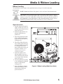
Ribbon Loading
To load ribbon, refer to Figure 4 (for right-hand units) or Figure 5 (for left-hand units).
NOTE: Do not load ribbon if the printer is to be used in the direct thermal mode.
CAUTION: When installing the ribbon roll on the ribbon supply spindle,
make sure it is pushed up against the stop and that the ribbon is aligned
squarely with its core. Do not use ribbon that is narrower than the media. If
the printhead is not protected by the smooth backing of the ribbon,
premature printhead failure may result due to excessive abrasion.
Right Hand Units
1. Push the ribbon roll onto the
supply spindle (N) as far as it
will go, so the ribbon feeds as
shown in Figure 4.
PAUSE
2. Install an empty ribbon core
onto the ribbon take-up
spindle (O).
3. Open the printhead assembly
(C) by unlatching the printhead lock lever (D) from the
locking pin (E).
MEDIA
RIBBON
ERROR
POWER
NEXT
PAUSE
FEED
SETUP/EXIT
CANCEL
CALIBRATE
O
N
4. Thread the ribbon below the
lower ribbon guide roller (P),
under the printhead assembly
(C), and up and over the
upper ribbon guide roller (Q)
as shown in Figure 4. Use
caution not to crease or
wrinkle the ribbon!
Q
OPEN
5. Attach the ribbon to the
take-up spindle core (use a
label if needed) and wind for
several turns in the direction
shown in Figure 4.
D
P
C
6. Close the printhead assembly
(C) by latching the printhead
lock lever (D) onto the
locking pin (E).
7. Insure the ribbon is located
between the Ribbon Sensor
and the Sensor Reflector
positioned above it.
DATA
PREVIOUS
E
Figure 4. Ribbon Loading (Right-Hand Units)
170PAX2-Series User’s Guide
5
Media & Ribbon Loading
Left Hand Units
1. Push the ribbon roll onto the
supply spindle (N) as far as it
will go, so the ribbon feeds
as shown in Figure 4.
PAUSE
2. Install an empty ribbon core
onto the ribbon take-up
spindle (O).
5. Attach the ribbon to the
take-up spindle core (use a
label if needed) and wind for
several turns in the direction
shown in Figure 5.
6. Close the printhead assembly
(C) by latching the printhead
lock lever (D) onto the
locking pin (E).
7. Insure the ribbon is located
between the Ribbon Sensor
and the Sensor Reflector
positioned above it.
MEDIA
RIBBON
ERROR
POWER
NEXT
PAUSE
FEED
SETUP/EXIT
CANCEL
CALIBRATE
3. Open the printhead assembly
(C) by unlatching the printhead lock lever (D) from the
locking pin (E).
4. Thread the ribbon below the
lower ribbon guide roller (P),
under the printhead assembly
(C), and up and over the
upper ribbon guide roller (Q)
as shown in Figure 5. Use
caution not to crease or
wrinkle the ribbon!
DATA
PREVIOUS
O
N
Q
D
OPEN
P
C
E
Figure 5. Ribbon Loading (Left-Hand Units)
Removing Used Ribbon
To remove used ribbon:
1. Open the printhead assembly (C) by unlatching the lock lever (D) from the locking pin (E).
2. Cut the ribbon between the upper ribbon guide roller (Q) and the ribbon take-up spindle (O).
3. Remove the used ribbon and the core together from the ribbon take-up spindle (O).
4. Remove the empty ribbon core from the ribbon supply spindle (N).
5. To load the new ribbon, refer to the previous “Ribbon Loading” topic.
6
170PAX2-Series User’s Guide
Media Sensor Position
Reflective Media Sensor
Some types of media have black marks printed on the underside of the backing material that act as
“Start of Label” indicators. These black marks are sensed by the reflective media sensor mounted on
the printer frame. The position of this sensor is not adjustable. If you will use this type of media, refer
to the “Specifications” section of this guide for information about black mark requirements.
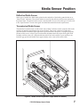
Transmissive Media Sensor
The transmissive media sensor is used to find “start of label” indicators such as a notch or hole in the
media or an interlabel gap (backing only) between labels. This sensor consists of a light source
(positioned below the media) and a light sensor (positioned above the media). To properly align the
position of this sensor, refer to Figure 6 and turn the adjustment knob (R) on the media guide shelf
assembly until the sensor (S) is aligned with the notch or hole in the media. If your media uses an
interlabel gap, position the media sensor approximately at the center of the media width.
T
S
Figure 6. Media Sensor Adjustment (Right-Hand Unit Shown)
170PAX2-Series User’s Guide
7
8
170PAX2-Series User’s Guide
Printer Operation
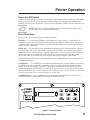
Power On/Off Switch
The Power On/Off Switch is located just to the left (or right) of the printer’s control panel. When this
switch is placed in the ON (1) position, the POWER light goes ON and the printer automatically
performs a Power On Self Test (POST). The Liquid Crystal Display validates the steps in the self test.
NOTE: Refer to the “Troubleshooting section of this manual if the printer stops
due to failing a test in the Power On Self Test.
Front Panel Keys
Four keys are used to control the various printer operations.
FEED Key — If you press the FEED key while the printer is idle or paused, a blank label is fed
immediately. If you press the FEED key while the printer is printing, one blank label is fed after the
completion of the current batch of labels. Once the blank label has been fed, pressing the FEED key
again will feed a second label.
PAUSE Key — The PAUSE key stops and restarts the printing process. When the printer is paused,
the PAUSE light will be ON. The first time you press the PAUSE key, any partially printed label is
completed; then the printing process is stopped. If the printer is idle when you press the PAUSE key,
no new print requests are accepted. Press the PAUSE key a second time to resume the printing
process. Press this key to remove any error messages and clear the Liquid Crystal Display.
The PAUSE mode can also be activated through pin 5 of the Applicator Port or by sending a ZPL II®
command to the printer.
CANCEL Key — The CANCEL key only functions when the printer is paused. When you press the
CANCEL key, the label format that is currently printing is canceled. If no label format is printing,
then the next one to be printed is canceled. If there are no label formats stored in the printer and
waiting to be printed, the CANCEL key is ignored. To clear the printer’s entire label format memory,
press and hold this key for several seconds until the DATA light turns OFF. The printer discards all of
the label format data it has received and returns to the idle state.
CALIBRATE Key — The CALIBRATE key functions only in the PAUSE mode. Press once to
recalibrate for proper media length, set media type, and set print method.
Figure 7. Control Panel
170PAX2-Series User’s Guide
9
Printer Operation
Liquid Crystal Display
The control panel shown in Figure 7 contains a backlit Liquid Crystal Display. It shows operational
status as well as programming modes and feature parameters.
Control Panel Keys
Five keys are used to set print and communication parameters.
BLACK OVAL KEYS — These two keys are used to change parameter values; the actual use
depends on the parameter being displayed. Common uses include increasing or decreasing a value,
answering yes or no, indicating ON or OFF, and scrolling through several choices.
PREVIOUS — Scrolls the display to the previous parameter.
NEXT — Scrolls the display to the next parameter.
SETUP/EXIT — Enters and exits the configuration mode.
Specific uses of these keys are explained with each parameter setting description in the
“Configuration and Calibration” section of this guide.
Front Panel Indicator Lights (LEDs)
LEDs on the front panel are a quick indication of the printer’s status.
LED
OFF
POWER Printer OFF or
(Green) no power to
printer.
PAUSE Normal
(Yellow) operation.
DATA
(Green)
No data being
received or
processed.
Normal
operation.
Media properly
loaded.
RIBBON Normal
(Yellow) operation.
Ribbon properly
loaded.
MEDIA
(Yellow)
ON
FLASHING
Power switch ON and power
being supplied to printer.
—-
Printer is paused (Printhead,
ribbon or paper error detected.
or PAUSE key was pressed. or
A Pause was requested from
the Applicator Port. or A pause
was received as part of the
label format).
Data processing or printing
taking place. No data is being
received.
—-
Printer is receiving data.
Flashing slows when the
printer cannot accept more
data, but returns to normal
once data is again being
received.
Out of media. (Printer paused,
LCD displays error message,
and PAUSE light is ON).
—-
Ribbon in (printer in direct
thermal mode) or no ribbon
loaded (printer in thermal
transfer mode). Printer is
paused, LCD displays error
message, and PAUSE light is ON.
—-
—-
Printer error exists. Check
LCD display for status.
.
ERROR No printer
(Orange) errors.
10
170PAX2-Series User’s Guide
Configuration and Calibration
After you have installed the media and ribbon, plugged in and turned on the AC Power, and the
printer has completed the Power On Self Test (POST), you may configure the printer parameters for
your application using the Liquid Crystal Display and the control panel keys. Not all choices pertain
to all applications. Choose only those settings that apply to your particular application.
NOTE: To restore the printer’s factory defaults, see “Leaving the Program
Mode” below or refer to “FEED Key and PAUSE Key” in the “Troubleshooting”
section of this guide.
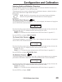
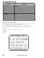
Introduction
Entering the Program Mode
To enter the Program Mode, press the SETUP/EXIT key when PRINTER READY is displayed.
Press either the NEXT key or the PREVIOUS key to scroll to the parameter you wish to set.
PRINTER READY
1.0 MB
nnnn
Changing Password-Protected Parameters
Certain parameters, indicated by an illustration of a key
after the title, are password
protected. The first attempt to change one of these parameters (pressing one of the black oval keys)
will require a password to be entered. This is done via the ENTER PASSWORD display.
ENTER PASSWORD
®
0000
+
The left oval key changes the digit position. The right oval key increases the digit value. After
entering the password, press the NEXT key. The parameter you were trying to change will be
displayed. If the password was entered correctly, you can now change the value.
The default password value is 1234. A new password can be configured by sending an appropriate
^KP (Define Password) ZPL II instruction to the printer.
NOTE: Once the password has been entered correctly, it will not have to be entered
again until leaving and re-entering the programming mode using the SETUP/EXIT key.
Leaving the Program Mode
Press the SETUP/EXIT key to leave the Program Mode. The display will show SAVE SETTINGS .
There are five choices: Permanent, Temporary, Cancel, Load Defaults, and Load Last Save.
SAVE SETTINGS
¬ PERMANENT ®
Pressing the left or right oval key changes the choices. Pressing the NEXT key activates the displayed
choice. Pressing PREVIOUS returns you to the last prompt.
Permanent — saved values are permanently stored in the printer even when the power is OFF.
Temporary — saves the new changes until changed again or until the power is turned OFF.
170PAX2-Series User’s Guide
11
Configuration and Calibration
Cancel — cancels all changes since pressing the SETUP/EXIT key except Darkness and
Tear Off (if they were changed).
Load Defaults — loads factory defaults as the printer’s operating parameters. These are reflected on
the following pages. (Loading factory defaults requires that a new printer calibration process be
performed and resetting of the printhead resistance, verifier port, and applicator port values.)
Load Last Save — reloads the values from the last permanent save as the printer’s operating parameters.
Configuration Process
The following sequences of parameters are shown in the order displayed when pressing the NEXT
key. Throughout this process, press the NEXT key to proceed to the next parameter; press
PREVIOUS to return to the prior parameter in the cycle. As you change a parameter, an asterisk (*) in
the upper left-hand corner of the display indicates that the value displayed is different from the one
that is currently active in the printer.
If you want the prompts displayed in a language other than English, press the PREVIOUS key and go
to page 32 to select the Printer Language. Exit the Program Mode, Save Permanent, then re-enter the
Program Mode. The Front Panel Display will now use the language selected.
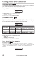
Setting Print Parameters
Setting Darkness
Darkness (burn duration) settings are dependent upon a variety of factors, including ribbon type,
media, and the condition of the printhead. You may adjust the darkness for consistent high-quality
printing.
NOTE: The FEED Key Self Test described in “Troubleshooting” can also be
used to determine the best darkness setting.
CAUTION: Set the darkness to the lowest setting possible for the desired
print quality. Darkness set too high for a given ribbon may cause ink
smearing and/or the printhead to burn through the ribbon.
If printing is too light, you should increase the darkness. If printing is too dark, or if there is
spreading or bleeding of printed areas, you should decrease the darkness. (If there are voids in printed
areas, adjust the toggle pressure.)
NOTE: The darkness setting takes effect right away. If labels are being printed,
results can be seen immediately.
DARKNESS
- nnnnnn
+10
+
Press the right oval key to increase darkness, or press the left oval key to decrease darkness.
Default: +10
Range: 0 to +30
Press the NEXT key to display TEAR OFF.
12
170PAX2-Series User’s Guide
Configuration and Calibration
Setting the Tear Off Position
The Tear Off Position adjusts the position of the media over the peel bar after printing. The label
and backing can be torn off or cut between labels. This also affects the dispense position in Peel
Off, Applicator, and Cutter modes.
TEAR OFF
- nnnnnn
+0
+
Press the right oval key to increase the value or the left oval key to decrease the value. Each press of
the key moves the tear off position by four dot rows (positive values move the media farther out over
the peel bar).
Default: +0
Range: -120 to +120
Press the NEXT key to display PRINT MODE.
Selecting the Print Mode
Print Mode settings tell the printer the method of media delivery that you wish to use. Be sure to
select a print mode your hardware configuration supports, since some selections displayed are
optional. “Applicator” is the recommended mode for an applicator.
PRINT MODE
¬ TEAR OFF ®
Press the right or left oval key to display other selections.
Default: Tear Off
Selections: Tear Off, Applicator, Rewind
Press the NEXT key to display MEDIA TYPE.
Selecting the Media Type
The Media Type parameter specifies the kind of media being used. “Continuous” media requires that
a label length instruction (^LLxxxx) be included in your ZPL or ZPL II label format.
With “non-continuous,” the printer feeds media to calculate label length (the distance between two
detections of the inter-label webbing, or alignment notch, or hole). “Non-Continuous” is the
recommended mode for an applicator.
MEDIA TYPE
NON-CONTINUOUS
Press the right or left oval key to display other selections.
Default: Non-Continuous
Selections: Non-Continuous, Continuous
Press the NEXT key to display SENSOR TYPE.
Selecting the Sensor Type
The Sensor Type parameter selects the appropriate sensor for the type of media being used.
SENSOR TYPE
¬ WEB
®
170PAX2-Series User’s Guide
13
Configuration and Calibration
Press the right or left oval key to display other selections.
Default: Web (used to sense notches or holes in media or liner between labels)
Selections: Web, Mark (used to sense black marks on the back of the media or liner)
Press the NEXT key to display PRINT METHOD.
Selecting the Print Method
The Print Method parameter specifies the method of printing: direct thermal (no ribbon) or thermal
transfer (using thermal-transfer media and ribbon).
WARNING: Selecting direct thermal when using thermal transfer media
and ribbon will create a warning condition. Verify that ribbon is correctly
installed or not installed in the printer, as required!
PRINT METHOD
THERMAL-TRANS.
Press the right or left oval key to display other selections.
Selections: Thermal Transfer, Direct Thermal
Press the NEXT key to display PRINT WIDTH.
Setting the Print Width
Print Width selects the media width. Setting the width too narrow may result in portions of your label
not being printed on the label material. In addition, this setting can affect the horizontal position of
the label format if you invert the image via the ^POI ZPL command. Setting the width too wide
wastes formatting memory and, in the case of right hand printers, can cause printing to occur on the
platen to the left of the actual label.
The units of measure can be changed from millimeters to inches to dots. Inches and millimeters are
shown as fractions of the dots per inch (for example, 4-101/203 IN is the value for 4 ½").
PRINT WIDTH
168 00/12
MM +
Press the right oval key to increase the value or change the unit of measure and press the left oval key
to change the selected character position. Select a print width that is at least as wide as your media.
Default: 6.62" (168 mm)
Range: 1 dot (1/8 mm or 1/12 mm) to 6.62" (168 mm)
Press the NEXT key to display MAXIMUM LENGTH.
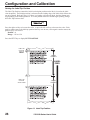
Setting the Maximum Label Length
Maximum Label Length specifies the distance from the leading edge of one label to the leading edge
of the next label. Refer to Figure 8. The interlabel gap is considered part of the label length. Setting
this parameter serves two functions:
•
The value of this setting determines the maximum label length value to be used
during the media portion of the calibration process.
•
Only a few labels are required to set the media sensors.
Always set the length to a value that is one step above the actual length of the label you are using.
For example, if the label length is 5 inches (126 mm), set the parameter for 6 inches (152 mm). If the
label length is 7.5 inches (190 mm), set the parameter for 8.0 inches (202 mm).
14
170PAX2-Series User’s Guide
Configuration and Calibration
NOTE: Before you begin the media and ribbon calibration procedure, be sure
the Maximum Length is set to a value one step greater than the actual media. If
the Maximum Length is set to a lower value, the printer will assume that continuous media is loaded.
NOTE: If the Maximum Label Length is changed to a value that is lower than
the length of the media being used, the printer will not calibrate.
MAXIMUM LENGTH
- 39.0IN
988MM +
Press the left oval key to decrease the value or press the right oval key to increase the value.
Default: 39.0 inches (988 mm)
Range: 2.0 inches (50 mm) to 39.0 inches (988 mm) in 1.0 inch (25.4 mm) increments.
Press the NEXT key to display LIST FONTS.
LABEL
FEED
LABEL
LENGTH
LABEL
LENGTH
Figure 8. Maximum Label Length
170PAX2-Series User’s Guide
15
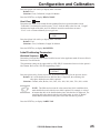
Configuration and Calibration
Listing Printer Information
List Fonts
This selection is used to print a label that lists all of the fonts currently available in the printer. Fonts
may be stored in optional font EPROMs and as part of firmware EPROMs, on an optional PCMCIA
memory card, or downloaded and stored in formatting memory (RAM).
LIST FONTS
PRINT
Press the right oval key to print a label listing all of the fonts.
Press the NEXT key to display LIST BAR CODES.
List Bar Codes
This selection is used to print a label that lists all of the bar codes currently available in the printer.
LIST BAR CODES
PRINT
Press the right oval key to print a label listing all of the bar codes.
Press the NEXT key to display LIST IMAGES.
List Images
This selection is used to print a label that lists all of the graphic images currently stored in the
printer’s DRAM, optional EPROM, or on an optional memory card.
LIST IMAGES
PRINT
Press the right oval key to print a label listing all of the images.
Press the NEXT key to display LIST FORMATS.
List Formats
This selection is used to print a label that lists all of the formats currently stored in the printer’s
DRAM, optional EPROM, or on an optional memory card. Press the right oval key to print the label.
LIST FORMATS
PRINT
Press the right oval key to print a label listing all of the formats.
Press the NEXT key to display LIST SETUP.
List Setup
This selection is used to print a label that lists the current printer configuration information (same as
the CANCEL Key Self Test). Press the right oval key to print a label listing the current printer
configuration.
LIST SETUP
PRINT
Press the right oval key to print a label listing the current printer configuration.
Press the NEXT key to display INITIALIZE CARD.
16
170PAX2-Series User’s Guide
Configuration and Calibration
Initialize Card
This selection initializes the optional memory card.
CAUTION: Perform this operation only when it is necessary to erase all
previously stored information in the optional memory card. Otherwise, press
the NEXT key to bypass this function and display SENSOR PROFILE.
INITIALIZE CARD
YES
1. Press the right oval key to select “YES”. If your printer is set to require a password, you will now
be prompted to enter the password. Enter the password then press the NEXT key.
INITIALIZE CARD
YES
2. The display will ask “INITIALIZE CARD?” Press the right oval key to select “YES”. The front
panel LCD will ask “ARE YOU SURE?”
ARE YOU SURE?
NO
YES
3. Press the right oval key to select “YES” and begin the initialization. or
Press the left oval key “NO” to cancel the request and return to the “INITIALIZE CARD” prompt.
4. Press the SETUP/EXIT key followed by the NEXT key.
If initialization is still in process, the front panel display will flash back and forth between the
two phrases “CHECKING B: MEMORY” and “PRINTER IDLE.”
When initialization is complete, the printer will automatically exit the configuration mode and the
front panel will display “PRINTER READY”.
NOTE: Depending on the amount of memory in the memory card, initialization
may take up to five minutes to complete.
170PAX2-Series User’s Guide
17
Configuration and Calibration
Media and Ribbon Sensor Calibration
When the print engine is first put into service, the following calibration process must be performed.
This allows the printer to establish the proper settings for the specific media and ribbon being used in
your application. If you have not reached this point by starting on page 11, you will have to enter the
“Program Mode” by pressing the SETUP/EXIT key when the PRINTER READY is displayed on the
LCD. Then press the NEXT key multiple times until the LCD displays the words “SENSOR
PROFILE.” Now continue below to perform the Media and Ribbon Sensor Calibration.
NOTE: Ensure that the “Media Type” and “Maximum Length” values have
been configured prior to performing this calibration process.
There are two different types of “Calibration” which can be performed on the print engine.
•
When the front panel CALIBRATE key is pressed, the print engine determines the
label length of noncontinuous media by sensing the time it takes for the media to
feed from one “Start of Label” indicator (web, notch, hole, black mark) to the next.
This process also determines if the application is using the direct thermal or thermal transfer print method by sensing the presence or absence of ribbon.
•
The full Media and Ribbon Sensor Calibration discussed here, performs the same
functions as the CALIBRATE key plus sensitivity adjustments on both the media
and ribbon sensors. These adjustments set parameters for the specific media and
ribbon currently installed in the printer.
If a different type of media and/or ribbon is used in the printer, the full calibration
must be performed (not just the front panel key). Press the NEXT key and perform
the “Media and Ribbon Calibration” procedure on the next page.
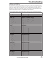
Sensor Profile
Press the right oval key to print a graphic representation (Media Sensor Profile) of the changes in
density between the media and the web (backing). The Sensor Profile may be used to help
troubleshoot media registration problems.
SENSOR PROFILE
PRINT
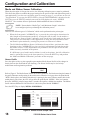
Refer to Figure 9. The Media Sensor Profile shows three conditions. The black area along the bottom of
the profile illustrates media passing by the media sensor. When the level goes above the point labeled
“WEB” (black spikes), the backing material only is passing by the sensor. When a notch or hole in the
media passes by the sensor, the level will go above the point labeled “MEDIA”. If the level remains
above the “MEDIA” point for longer than .5 seconds, this signifies a Media Out condition. The Ribbon
Profile indicates Ribbon IN if the black level is above the point labeled “RIBBON”.
Press the NEXT key to display MEDIA AND RIBBON.
Figure 9. Sensor Profile Sample Label
18
170PAX2-Series User’s Guide
Configuration and Calibration
Media and Ribbon Calibration
Changing the type of ribbon and/or media may require adjustments to the sensitivity of the media and
ribbon sensors. Indications that the sensitivity may need to be adjusted would be a RIBBON light ON
with the ribbon properly installed or non-continuous media being treated as continuous media.
The following procedure is used to adjust the sensitivity of both the media and ribbon sensors. To be
sure this procedure is required, first read the information presented on the previous page.
This procedure must be followed exactly as presented. To bypass this procedure, press the NEXT key.
MEDIA AND RIBBON
CALIBRATE
1. Press the right oval key to start the calibration procedure. LOAD BACKING will be displayed.
LOAD BACKING
CANCEL CONTINUE
2. Press the left oval key to cancel the operation or do the following:
Open the printhead. Remove a sufficient number of labels from the backing material to ensure
that only backing material is threaded through the entire media path.
3. Press the right oval key to continue. REMOVE RIBBON will be displayed.
REMOVE RIBBON
CANCEL CONTINUE
4. Press the left oval key to cancel the operation or press NEXT to display HOST PORT, or remove
the ribbon (sliding it away from the mainframe will have the same effect as removing it).
5. Close the printhead.
6. Press the right oval key to continue (start the calibration process) or the left oval key to cancel the
operation. If you choose to continue, CALIBRATING...PLEASE WAIT will be displayed.
CALIBRATING
PLEASE WAIT
The sensitivity adjustments for the media and ribbon sensors are now being made. This process takes
only a few seconds.
RELOAD ALL
CONTINUE
7. When RELOAD ALL is displayed, open the printhead and pull the media forward until a label is
positioned under the media sensor. Move the ribbon back to its proper position.
8. Close the printhead.
9. Press the right oval key to continue the calibration procedure. Label Length will be calibrated and
MEDIA AND RIBBON will be displayed.
MEDIA AND RIBBON
CALIBRATE
The sensitivity adjustments for the media and ribbon sensors are now completed.
Press the NEXT key to display HOST PORT, or turn to page 11 to exit the programming mode.
170PAX2-Series User’s Guide
19
Configuration and Calibration
Setting Communication Parameters
Communication parameters must be set correctly for the printer to receive data from the host. These
parameters ensure that the printer and host are “speaking the same language.”
All communications parameters are password-protected. See page 11.
Setting the Host Port
Select the communications port that matches the one being used by the host computer.
HOST PORT
¬ MAIN RS232
®
Press the right or left oval key to display other selections.
Default: Main RS232
Selections: Main RS232, RS422/485, RS485 Multidrop, Parallel
Press the NEXT key to display BAUD. (If Parallel was selected, go to “Setting the Protocol”.)
Setting the Baud Rate
The baud rate of the printer must match the baud rate of the host for communications to take place.
Select the baud rate that matches the one being used by the host.
-
BAUD
9600
+
Press the right oval key to increase the value, or press the left oval key to decrease the value.
Default: 9600
Selections: 110, 300, 600, 1200, 2400, 4800, 9600, 19200, 28800, 57600
Press the NEXT key to display DATA BITS.
Setting the Data Bits
The data bits of the printer must match the data bits of the host for communications to take place.
Select the data bits that match the ones being used by the host.
NOTE: This parameter must be set to 8 data bits to use the Code Page 850 character set. See the ZPL II Programming Guide for further information.
-
DATA BITS
7 BITS
+
Press the right or left oval key to display other selections.
Default: 7 Bits
Selections: 7 Bits, 8 Bits
Press the NEXT key to display PARITY.
20
170PAX2-Series User’s Guide
Configuration and Calibration
Setting the Parity
The parity of the printer must match the parity of the host for communications to take place. Select
the parity that matches the one being used by the host.
PARITY
- EVEN
+
Press the right or left oval key to display other selections.
Default: Even
Selections: Even, None, Odd
Press the NEXT key to display STOP BITS.
Setting the Stop Bits
The stop bits of the printer must match the stop bits of the host for communications to take place.
Select the number of stop bits that match the quantity being used by the host.
-
STOP BITS
1 STOP BIT
+
Press the right or left oval key to display other selections.
Default: 1 Stop Bit
Selections: 1 Stop Bit, 2 Stop Bits
Press the NEXT key to display HOST HANDSHAKE.
Setting the Host Handshake
The handshake protocol of the printer must match the handshake protocol of the host for communications to take place. Select the handshake protocol that matches the one being used by the host.
HOST HANDSHAKE
¬ XON/XOFF ®
Press the right or left oval key to display other selections.
Default: XON/XOFF
Selections: XON/XOFF, DSR/DTR
Press the NEXT key to display PROTOCOL.
Setting the Protocol
The serial port supports Error Detection Protocol which sends and receives data in packets. The
selected protocol must be compatible with your host computer and your application software. Select
the protocol that is required by the host.
NOTE: Do not enable Error Detection unless your Host is programmed to use
it. For more information, refer to the ZPL II Programming Guide.
PROTOCOL
¬ NONE
®
Press the right or left oval key to display other selections.
Default: None (Always select “None” if you are not using error checking software.)
Selections: None, Zebra Protocol, ACK/NACK Protocol
170PAX2-Series User’s Guide
21
Configuration and Calibration
NOTE: Zebra Protocol is the same as ACK/NACK Protocol, except the
response messages are sequenced.
NOTE: If Zebra Protocol is selected, the printer must use “DSR/DTR” Host
Handshake Protocol.
Press the NEXT key to display NETWORK ID.
Setting the Network ID
Network ID is used to assign a unique number to a printer used in a selective calling network. This
gives the host the means to address a specific printer. A Network ID is not required when connected in
an Ethernet Network.
®
NETWORK ID
000
+
Press the left oval key to move to the next digit position, and press the right oval key to increase the
value of the selected digit.
Default: 000
Range: 000 - 999
Press the NEXT key to display COMMUNICATIONS.
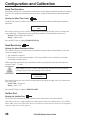
Setting the Communications Mode
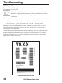
The Communications Diagnostics Mode is a tool to check the interconnection between the printer and
the host. When DIAGNOSTICS is selected, all data sent from the host to the printer will be printed
as an ASCII hex printout. The printer prints all ASCII characters received, including ASCII control
codes (for example, CR [Carriage Return]). A sample printout is shown in Figure 10.
COMMUNICATIONS
¬NORMAL MODE®
Press the right or left oval key to display other selections.
Default: Normal Mode
Selections: Normal Mode, Diagnostics
NOTES on diagnostic printouts:
An FE indicates a framing error.
An OE indicates an overrun error.
A PE indicates a parity error.
An NE indicates noise.
For any errors, check that your communication parameters are correct. Set the
print width equal to or less than the label
width used for the test.
Figure 10. Diagnostics Sample Label
Press the NEXT key to display CONTROL PREFIX.
22
170PAX2-Series User’s Guide
Configuration and Calibration
Selecting Prefix and Delimiter Characters
Prefix and delimiter characters are two-digit hex values used within the ZPL/ZPL II formats sent to
the printer. See “Appendix C” for an ASCII Code chart.
The printer uses the most recently configured prefix and delimiter characters, whether included as
part of a ZPL II instruction or input from the front panel.
NOTE: DO NOT use the same hex value as the control, format, and delimiter
characters. The printer requires different characters to function properly.
The Control Prefix Character
The control prefix character is a two-digit hex value. Once configured, this character will signify the
start of a ZPL/ZPL II control instruction.
CONTROL PREFIX
® <n> 7EH +
Press the left oval key to move to the next digit position, and press the right oval key to increase the
value of the digit. (The “H” is displayed but not entered as part of the value.)
Default: 7E (tilde)
Range: 00 - FF (exclude the values indicated on the ASCII Code Chart in “Appendix C”)
Press the NEXT key to display FORMAT PREFIX.
The Format Prefix Character
The format prefix character is a two-digit hex value. Once configured, this character will signify the
start of a ZPL or ZPL II format instruction.
FORMAT PREFIX
® <^> 5EH +
Press the left oval key to move to the next digit position, and press the right oval key to increase the
value of the digit. (The “H” is displayed but not entered as part of the value.)
Default: 5E (caret)
Range: 00 - FF (exclude the values indicated on the ASCII Code Chart in “Appendix C”)
Press the NEXT key to display DELIMITER CHAR.
The Delimiter Character
The delimiter character is a two-digit hex value. Once configured, this character acts as a parameter
place marker in ZPL/ZPL II. Refer to the “ZPL II Programming Guide” for more information.
DELIMITER CHAR
® <,> 2CH +
Press the left oval key to move to the next digit position, and press the right oval key to increase the
value of the digit. (The “H” is displayed but not entered as part of the value.)
Default: 2C (comma)
Range: 00 - FF (exclude the values indicated on the ASCII Code Chart in “Appendix C”)
Press the NEXT key to display MODE.
170PAX2-Series User’s Guide
23
Configuration and Calibration
Selecting ZPL Mode
The printer accepts label formats written in either ZPL or ZPL II. Refer to the “ZPL II Programming
Guide” for more information on the differences between ZPL and ZPL II.
The printer will remain in the selected mode until changed by this front panel instruction or by
sending a ZPL/ZPL II command to the printer.
ZPL MODE
¬ ZPL II
®
Press the right or left oval key to display other selections.
Default: ZPL II
Selections: ZPL II, ZPL
Press the NEXT key to display RIBBON TENSION.
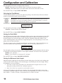
Setting Ribbon Tension
This parameter sets the tension applied to the Ribbon Supply Spindle. A setting of Low, Medium, or
High is determined by the combination of ribbon width and length. Use the tables below to determine
the recommended setting for your specific application. If ribbon wrinkle, or smudging or scuffing of
ink on the label material is evident, reduce the tension to the next lower setting.
RIBBON TENSION
¬HIGH
®
Ribbon Width
Ribbon Tension Setting
300 Meter Roll
450 Meter Roll
600 Meter Roll
900 Meter Roll
3” to 5”
LOW
LOW
LOW
LOW
4” to 6”
LOW
5” to 7”
LOW - MEDIUM
LOW - MEDIUM LOW - MEDIUM
MEDIUM
MEDIUM - HIGH
MEDIUM
HIGH
Press the right or left oval key to display other selections.
Default: High
Selections: Low, Medium, High
Press the NEXT key to display MEDIA POWER UP.
Power Up and Head Close Parameters
Media Power Up
Determines the action of the media when the printer is turned ON. “Calibration” recalibrates the
media sensors, “Feed” feeds the label to the first web, “Length” calculates the length of the label, and
“No Motion” means the media does not move. “No Motion” is the recommended mode for an
applicator.
MEDIA POWER UP
¬FEED
®
24
170PAX2-Series User’s Guide
Configuration and Calibration
Press the right or left oval key to display other selections.
Default: Feed
Selections: Feed, Calibration, Length, No Motion
Press the NEXT key to display HEAD CLOSE.
Head Close
Determines the action of the media after the printhead has been opened and then closed.
“Calibration” recalibrates the media sensors, “Feed” feeds the label to the first web, “Length”
calculates the length of the label, and “No Motion” means the media does not move.
“Feed” is the recommended mode for an applicator.
HEAD CLOSE
¬FEED
®
Press the right or left oval key to display other selections.
Default: Feed
Selections: Feed, Calibration, Length, No Motion
Press the NEXT key to display BACKFEED.
Label Positioning Parameters
Backfeed Sequence
Determines when and how much label backfeed occurs in the Applicator mode. It has no effect in
Rewind or Tear-Off modes.
This parameter setting can be superseded by a ZPL/ZPL II instruction when received as part of a
label format. Refer to the “ZPL II Programming Guide.”
BACKFEED
¬DEFAULT
®
Press the right oval key for the next choice, or press the left oval key for the previous choice.
Default: 90% of the backfeed occurs after the label is dispensed; the remaining 10%
takes place before the next label is printed.
Selections: Default; After, Before, 10%, 20%, 30%, 40%, 50%, 60%, 70%, 80%, or 90%
NOTE: The difference between the value entered and 100% establishes how
much backfeed occurs before the next label is printed. For example, a value of
40 means that 40% of the backfeed takes place after the label is dispensed. The
remaining 60% takes place before the next label prints. A value of “Before”
means that all backfeed will take place before the next label is printed.
Press the NEXT key to display LABEL TOP.
170PAX2-Series User’s Guide
25
Configuration and Calibration
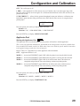
Setting the Label Top Position
The Label Top Position controls the initial vertical print position on the label (viewed as the label
exits the printer). The Default position is referenced to the leading edge of the label which follows the
one to be printed. Refer to Figure 11. If there is a lengthy web between labels, the label format may
begin printing on the backing material. To set the position where the format begins printing, change
the Label Top Position value.
LABEL TOP +000
- nnnnnnn +
Press the right oval key to increase the value , or press the left oval key to decrease the value. Each
positive number moves the label top position down by one dot row; each negative number moves the
position up by one dot row.
Default: +0
Range: -120 to +120
Press the NEXT key to display LEFT POSITION.
LABEL TOP
POSITION
LABEL
LENGTH
LABEL
FEED
LABEL TOP
POSITION
+80 DOT ROWS
LABEL
LENGTH
Figure 11. Label Top Position
26
170PAX2-Series User’s Guide
Configuration and Calibration
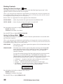
Setting the Left Position
The Left Position controls the initial print position from the left edge of a label (viewed as the label
exits the printer). The Default position is referenced to the left edge of the media. Refer to Figure 12.
Depending on the width of the media, the label format may begin printing on the backing material or
on the platen. To set the position where the format begins printing, change the Left Position value.
LEFT POSITION
®
+ 0000
+
Press the left oval key to move the cursor to the next digit, and press the right oval key to change the
+/- value and increase the value of the digit (“+” shifts to the left; “-” shifts to the right.) The
displayed value represents the number of dot positions the format will shift right or left.
Default: 0000
Range: -9999 to +9999 (If a negative value is required, enter the numeric value first, then
change the plus to a minus sign.)
Press the NEXT key to display HEAD TEST COUNT.
LEFT
POSITION
LABEL
FEED
LEFT
POSITION
-35 DOT ROWS
LABEL
LENGTH
Figure 12. Left Position
170PAX2-Series User’s Guide
27
Configuration and Calibration
Head Test Function
Periodically a Head Test is automatically performed to ensure that the printhead elements are working
correctly. This parameter determines how many labels are printed between these internal printhead
tests.
Setting the Head Test Count
The Head Test Count is used to select the head test interval (the number of labels printed between
head tests).
HEAD TEST COUNT
®
0000
+
Press the left oval key to move to the next digit position, and press the right oval key to change the
value of the digit. The displayed value represents the number of labels printed between tests.
Default: 0000 (disables the head test)
Range: 0000 to 9999
Press the NEXT key to display HEAD RESISTOR.
Head Resistance
Setting the Head Resistance Value
This value has been pre-set at the factory to match the resistance value of the printhead. It will not
need to be changed, unless:
1. The printhead is replaced.
2. The printer is set to the factory defaults. (The factory default value is usually lower than the
actual head resistance value.)
Before replacing a printhead, look on the bottom of the new printhead for the label that shows the
resistance (ohm – Ω) value.
CAUTION: DO NOT set the value higher than that shown on the printhead.
Setting a higher value may damage the printhead.
HEAD RESISTOR
® 0500 OHMS +
Press the left oval key to move to the next digit position, and press the right oval key to increase the
value of the digit.
Initial Value: Factory set
Range: 0500 - 1175
Press the NEXT key to display VERIFIER PORT.
Verifier Port
Setting the Verifier Port
The Verifier Port determines how the optional verifier will interface with a Zebra printer.
This setting is factory set and should not be changed unless the factory defaults have been reloaded.
Please make a note of it! While other choices are valid, the printer must be returned to its designated
setting in order for it to work properly.
28
170PAX2-Series User’s Guide
Configuration and Calibration
OFF - The verifier port is off.
1 ERR — Label reprinted if verifier detects an error. If the bar code is near the upper edge of the
label, the label will feed out far enough to be verified and then backfeed to allow the next label to be
printed and verified.
2 VER-THRUPUT — Allows for the greatest throughput but may not indicate a verification error
immediately upon detection. May print from one to three labels before an error is recognized and
printing stops.
VERIFIER
¬OFF
PORT
®
Press the right or left oval key to display other selections.
Default: Off
Selections: Off, 1 VER-RPRNT ERR, 2 VER-THRUPUT
Press the NEXT key to display APPLICATOR PORT.
Applicator Port
Setting the Applicator Port
The Applicator Port is used to determine how the printer will interface with the applicator.
This is set by the applicator manufacturer and should not be changed unless the factory defaults have
been reloaded. Please make a note of it! While other choices are valid, the printer must be returned to
its designated setting in order for it to work properly.
Refer to Table 5 in “Appendix B” for more applicator cable information.
OFF — Applicator interface is off.
MODE 1 — Asserts the END PRINT signal LOW while the printer is moving the label forward.
MODE 2 — Asserts the END PRINT signal HIGH while the printer is moving the label forward.
MODE 3 — Asserts the END PRINT signal LOW for 20 milliseconds when a label has been
completed and positioned. Not asserted during continuous printing modes.
MODE 4 — Asserts the END PRINT signal HIGH for 20 milliseconds when a label has been
completed and positioned. Not asserted during continuous printing modes.
APPLICATOR PORT
¬OFF
®
Press the right or left oval key to display other selections.
Default: Off
Selections: Off, MODE 1, MODE 2, MODE 3, MODE 4
Press the NEXT key to display START PRINT SIG.
170PAX2-Series User’s Guide
29
Printing Controls
Setting the Start Print Signal
This parameter determines how the printer will react to the Start Print Signal input on pin 3 of the
applicator interface connector at the rear of the printer.
This is set by the applicator manufacturer and should not be changed unless the factory defaults have
been reloaded. Please make a note of it! While other choices are valid, the printer must be returned
to its designated setting in order for it to work properly.
Refer to Table 5 in “Appendix B” for more applicator cable information.
PULSE MODE — A label will print when the signal transitions from HIGH to LOW.
LEVEL MODE — Labels will print as long as the signal is asserted LOW.
START PRINT SIG
¬PULSE MODE
®
Press the right or left oval key to display other selections.
Default: Pulse Mode
Selections: Pulse Mode, Level Mode
Press the NEXT key to display RESYNCH MODE.
Setting the Resync Mode
This parameter determines how the printer will react if the label synchronization is lost and the label
top is not where expected.
This is set by the applicator manufacturer and should not be changed unless the factory defaults have
been reloaded. Please make a note of it! While other choices are valid, the printer must be returned to
its designated setting in order for it to work properly.
FEED MODE
— If the label top is not where expected, the printer will feed a blank label to find
the label top position.
ERROR MODE — If the label top is not where expected, the printer will stop, enter the PAUSED
mode, display the message “Error Condition Feed Label”, flash the ERROR
LED, and assert the “Service Required” signal (pin 10 on the Applicator
Interface Connector).
To resync the media to the top of the label in this mode, the user must press the
PAUSE key to exit the PAUSED state. The ERROR LED will then stop
flashing and the “Service Required” signal will be de-asserted. The action of the
printer is then determined by the “Head Close” configuration selection:
•
•
•
•
“Calibration” – the printer feeds labels and recalibrates the media sensors.
“Feed” – the printer feeds the labels to the next web.
“Length” – the printer feeds labels and calculates the label length.
“No Motion” – the media does not move. The user must press the FEED
key to cause the printer to resync to the start of the next label.
RESYNCH MODE
¬ FEED MODE ®
Press the right or left oval key to display other selections.
Default: Feed Mode
Selections: Feed Mode, Error Mode
Press the NEXT key to display RIBBON LOW.
30
170PAX2-Series User’s Guide
Configuration and Calibration
Selecting the Ribbon Low Feature
When the Ribbon Low feature is enabled, the “Ribbon Low” output signal (Pin 9) on the applicator
port is functional. When the amount of ribbon on the supply spindle reaches a specific low level, the
output signal will assert HIGH to provide a “Ribbon Low” warning.
When the Ribbon Low feature is disabled, the output signal (Pin 9) will not function, the “Low
Ribbon” warning is not displayed, and the printer will continue to print until it runs out of ribbon.
RIBBON LOW MODE
¬ ENABLED ®
Press the right or left oval key to display other selections.
Default: Enabled
Selections: Enabled, Disabled
Press the NEXT key to display REPRINT MODE.
Reprint Mode
When the Reprint feature is enabled, the “Reprint” input signal (Pin 6) on the applicator port is
functional. When the input signal is asserted, the last label printed will be printed again. (This
includes non-printing labels.) When the Reprint feature is disabled, the “Reprint” input signal is
ignored.
NOTE: The ^SP command is ignored when the Reprint feature is enabled.
When the Reprint feature is disabled, the ^SP command can be used. In addition,
when a received label format is canceled prior to printing, the “reprint” function
for the previous label is also canceled.
¬
REPRINT MODE
DISABLED ®
Press the right or left oval key to display other selections.
Default: Disabled
Selections: Disabled, Enabled
Press the NEXT key to display WEB SENSOR
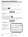
Sensor Values
The following eight parameters — Web Sensor, Media Sensor, Ribbon Sensor, Mark Sensor,
Mark Media Sensor, Media LED, Ribbon LED, and Mark LED — are automatically calculated
during the calibration procedure and typically do not require adjustment. Additional information
about these values can be found in the 170PAX-Series Maintenance Manual (P/N 49803L).
Press the NEXT key to display LCD ADJUST.
170PAX2-Series User’s Guide
31
Configuration and Calibration
LCD Adjust
Adjusts the brightness of the Liquid Crystal Display.
LCD ADJUST 00
-n
+
Press the left oval key to decrease the brightness; the right oval key to increase the brightness.
Default: 00
Range: 00 to 19
Press the NEXT key to display LANGUAGE
Printer Language
Selecting the Liquid Crystal Display (LCD) Language.
Allows you to specify the language for the LCD prompts and error messages language. The selected
language will also be print on the following labels: setup/configuration, and the font, bar code,
graphic, and format listings.
¬
LANGUAGE
ENGLISH ®
NOTE: At the beginning of the programming process on page 12, it is recommended that the user press the PREVIOUS key to display this parameter and
allow for international language selection. If you want the prompts displayed in a
language other than English, select the Printer Language, exit the Program Mode,
Save Permanent, then re-enter the Program Mode. The Front Panel Display will
now use the language selected. This allows the user to read the programming
prompts in the desired language.
Press the right oval key to select a language.
Default: English
Selections: English, Spanish, French, German, Italian, Norwegian, Portuguese, Swedish,
Spanish2, Dutch, Finnish, Custom
If this is the last configuration parameter, press the SETUP/EXIT key, select the desired Save Mode
(typically “Permanent”), then press the NEXT key to end the configuration process. Refer to
“Leaving the Program Mode” on page 11.
32
170PAX2-Series User’s Guide
Care & Adjustments
Cleaning
CAUTION: Use only the cleaning agents indicated. Zebra Technologies
Corporation will not be responsible for damage caused by any other
cleaning materials used on the 170PAX2-Series print engine.
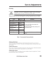
Table 1 provides a recommended cleaning schedule. Cleaning swabs saturated with 70% Isopropyl
Alcohol are available from your Zebra distributor as a Preventive Maintenance Kit (part # 01429).
AREA
METHOD
INTERVAL
See Figures 13 and 14 for parts locations.
Printhead (1)
Alcohol
Platen Roller (2)
Alcohol
Media Path
Alcohol
After every roll of ribbon when printing in the
thermal transfer mode.
Transmissive Media
Air blow
Sensor (3)
After every roll of media when printing in the
direct thermal mode.
Reflective Media
Air blow
Sensor (4)
Ribbon Sensor (5)
Air blow
Door-Open Sensor (6)
Air blow
Peel Bar (7)
Alcohol
After every roll of media or more often if
needed.
Table 1. Recommended Cleaning Schedule
Cleaning the Exterior
The exterior surfaces of the printer may be cleaned with a lint free cloth. Do not use harsh or
abrasive cleaning agents or solvents! If necessary, a mild detergent solution or desktop cleaner may be
used sparingly.
Cleaning the Interior
Remove any accumulated dirt and lint from the interior of the printer using a soft bristle brush and/or
vacuum cleaner. This area should be inspected after every roll of ribbon.
Cleaning the Sensors
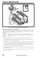
To ensure proper operation of the printer, all sensors should be cleaned on a regular basis. To locate
the position of these sensors, refer to Figure 13.
170PAX2-Series User’s Guide
33
Care & Adjustments
COVER
HINGE
6
3
4
5
Figure 13. Sensor Locations (Right-Hand Unit Shown)
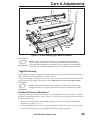
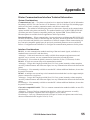
Cleaning the Printhead and Platen Roller
Inconsistent print quality, such as voids in the bar code or graphics, or light print may indicate a dirty
printhead. Media movement problems may indicate a dirty platen. For optimum print quality, perform
the following cleaning procedure after every roll of ribbon.
NOTE: If print quality has degraded and you have not changed to a different type
of media or ribbon, it should not be necessary to change the burn temperature or the
toggle pressure.
To clean the printhead and platen roller, refer to Figure 14 and perform the following steps:
1. Open the printhead assembly (C) by lifting the printhead lock lever (D) upward away from the
locking pin (E), and remove the media and ribbon.
2. Brush, vacuum, or air blow any accumulated lint and paper dust away from the rollers. It is good
practice to clean the various media, ribbon, and door-open sensors at this time. See Figure 13.
3. Use a cleaning swab saturated with alcohol and wipe the print elements from end to end. The
print elements form the grayish/black strip (1) just behind the chrome strip on the underside of
the printhead. Allow a few seconds for the solvent to evaporate.
4. Use a lint-free cloth moistened with alcohol to clean the platen roller (2) and other rollers. Rotate
the rollers while cleaning.
5. Reload the ribbon and/or media, latch the printhead, and continue printing. (Turn the printer ON
if previously turned OFF.)
34
170PAX2-Series User’s Guide
Care & Adjustments
D
1
C
CLEANING
SWAB
E
2
7
Figure 14. Printer Cleaning (Right-Hand Unit Shown)
NOTE: If print quality has not improved, try cleaning the printhead with the
Save-a-Printhead cleaning film. This specially coated material removes contamination buildup without damaging the printhead. Call your authorized Zebra distributor
to order the Save-a-Printhead cleaning kit for the 170PAX2 printer (part # 38902M).
Toggle Positioning
Proper Toggle positioning is important for proper print quality. The toggles should be positioned 1/4
of the width in from the media edges (see Figure 15 inset).
To position the toggles, loosen the set screws (T) with a 1.5 mm Allen wrench and slide them to the
desired position on the toggle pivot shaft (U); then, tighten the set screws ½ turn past contact.
NOTE: Perform the Printhead Pressure Adjustment which follows, and make sure
the toggle pressure is even, otherwise the media may drift or the ribbon may wrinkle.
Printhead Pressure Adjustment
If printing is too light, or if thick or thin media is used, printhead pressure may need to be adjusted.
During this adjustment procedure, refer to Figure 15. (Use the lowest pressure possible that provides
the desired print quality.)
1. Refer to the Configuration process starting on page 11 and lower the darkness setting (burn
duration) to a value of “2” or “3”.
2. Refer to the PAUSE Key Self Test on page 43 and print test labels at 2” (50.8 mm) per second.
3. Loosen the locking nuts (R) on the threaded shafts of both toggle assemblies.
170PAX2-Series User’s Guide
35
Care & Adjustments
4. Use the adjusting nuts (S) to increase or decrease the spring pressure until the left and right edges
of the printed area are equally dark.
5. Increase darkness to the optimum level for the media being used.
6. Hold the adjusting nuts (S) in position, and tighten the locking nuts (R) against them.
NOTE: Printhead and drive system (belts and bearings) life can be maximized
by using the lowest pressure that produces the desired print quality.
R
1/4
U
T
S
Figure 15. Printhead Pressure (Right-Hand Unit Shown)
36
170PAX2-Series User’s Guide
1/2
1/4
Troubleshooting
Power On Self Test
A Power On Self Test (POST) is performed each time the printer is turned ON. During this test, the
front panel lights (LEDs) will turn ON and OFF to ensure proper operation. At the end of this self
test, only the POWER LED will remain lit. Once the Power On Self Test is complete, the media is
advanced to the proper resting position, as determined by the programmed Media Feed setting.
To initiate the Power On Self Test, turn the printer ON using the power switch on the control panel.
The POWER LED will go ON. The other control panel LEDs and the LCD monitor the progress and
indicate the results of the individual tests. All displayed prompts occur in English; however when a
test fails, the prompt will also rotate through the international languages.
The normal self test sequence, which occurs each time the printer is turned on, is as follows:
1.
2.
All lights turn on simultaneously and then turn off in
sequence through the following steps.
SRAM functionality test performed.
SRAM Test
3.
Option ROM Test
4.
Printhead Test
5.
Processor Test
Processor functionality test performed. The word
“Failed” will be added to the display if the test fails.
6.
E-Cubed Test
E-cubed functionality test performed. The word
“Failed” will be added to the display if the test fails.
7.
EEPROM Test
8.
Memory Card Test
9.
10
.
PRINTER READY
x.x MB
VXX.X.X
Option ROM functionality test performed. The
words “Not Installed” will be added to the display if
optional ROM is not used.
Printhead is checked for proper operation.
EEPROM/PROM functionality test performed. The
word “Failed” will be added to the display if the test
fails.
Optional PCMCIA Memory Card functionality test
performed. The words “Not Installed” will be added
to the display if no card is present.
Depending on how the ^MF ( Media Feed)
instruction is set, the printer will feed to the first web
or label length, calibrate ribbon and media sensors,
or set label length and feed one or more labels.
Printer is ready for operation. Refer to
“Configuration and Calibration” to set specific
parameters. Designate prompt language with the
^KL command or from the menu.
170PAX2-Series User’s Guide
37
Troubleshooting
The following tables provide trouble symptoms, a diagnosis of specific causes, and a recommended
action which should result in proper printer operation.
If you are in need of technical assistance, contact your equipment supplier.
Power On Troubleshooting
SYMPTOM
DIAGNOSIS
All lights on, but
Internal electronic or
nothing displays on
firmware failure.
the LCD, and the
printer locks up.
Printer locks up while Main Logic Board failure.
running the Power
On Self Test.
EEPROM checksum is
EEPROM TEST
incorrect.
FAILED
ACTION
Call a service technician.
Call a service technician.
Call a service technician.
Printer Troubleshooting
SYMPTOM
DIAGNOSIS
For Thermal Transfer:
Ribbon not loaded or
incorrectly loaded.
Printer stops;
Ribbon Sensor not detectRIBBON light ON,
ing ribbon that is loaded
ERROR light flashes. correctly.
For Direct Thermal:
WARNING
Ribbon loaded.
RIBBON IN
or
RIBBON light ON,
Media blocking the
ERROR light flashes. Ribbon Sensor.
No media loaded or
ERROR CONDITION
incorrectly loaded.
PAPER OUT
Load ribbon correctly. See
“Ribbon Loading” on page 5.
Printer stops;
Misadjusted Media
MEDIA light ON,
Sensor.
ERROR light flashes. Printer set for noncontinuous media, but
continuous media is
loaded.
Printhead
is not fully
ERROR CONDITION
closed.
HEAD OPEN
Check position of the Media
Sensor.
Install proper media or reset
printer for current media type
and perform calibration.
ERROR CONDITION
RIBBON OUT
Printer stops and
Head Open Sensor not
ERROR light flashes. working properly.
Printhead is overheated.
WARNING
HEAD TOO HOT
Printer stops and
ERROR light flashes.
38
ACTION
Perform “Media and Ribbon
Sensor Calibration” on
page 18.
Remove ribbon. Load media
correctly. Perform “Media and
Ribbon Sensor Calibration” on
page 18.
Load media correctly. See
“Media Loading” on page 3.
Close printhead completely.
Call a service technician.
Allow printer to cool. Printing
resumes when the printhead
elements cool to operating
temperature.
170PAX2-Series User’s Guide
Troubleshooting
SYMPTOM
WARNING
HEAD COLD
DIAGNOSIS
ACTION
Printhead is not hot
enough to print properly.
Printing continues while
printhead heats up. If error
remains, environment may be
too cold for proper printing.
Relocate printer to warmer
area. Verify print quality.
To correct the situation, call a
service technician to replace
the printhead.
To override this error message, turn off the Head Test in
the Printer Configuration.
You may do any of the
following:
ERROR light flashes.
ERROR CONDITION
HEAD ELEMENT BAD
Printhead element is bad
or going bad.
Experiencing print
quality problems.
Printer stops and
PAUSE light goes
ON. The LCD
displays:
Not enough memory to
perform function shown
on the second line.
Explanation of Errors:
1.Creating Bitmap Bitmap size (label
length/width) does not fit
in available memory.
A. With PAUSE on, send a
~HM command to the printer
to display the amount of free
memory. Then either:
2.Storing Bitmap Not enough memory
available to store the
bitmap created.
Redesign graphic/format
to fit available memory or
remove items from memory to
create more space. or
OUT OF MEMORY
BUILDING FORMAT
3.Building Format Label is too complex.
Press PAUSE to skip the
formatting step in process and
proceed to the next step.
OUT OF MEMORY
STORING FORMAT
4.Storing Format Format is too large to fit
in available memory.
B. With PAUSE on, press
CANCEL. The printer
skips the current label
formatting process and
goes on to the next label.
OUT OF MEMORY
CREATING BITMAP
OUT OF MEMORY
STORING BITMAP
OUT OF MEMORY
STORING GRAPHIC
OUT OF MEMORY
STORING FONT
Long tracks of
missing print on
several labels.
Fine, angular gray
lines on blank labels.
5. Storing Graphic Graphic image is too large C. Turn power OFF and then
to fit in available memory. ON to clear printer memory
and start over.
6. Storing Font D. Upgrade the printer to a
Not enough memory
larger memory size.
available to store the font.
Wrinkled ribbon.
See “Wrinkled Ribbon”
later in this section.
Print element damaged.
Call a service technician.
Wrinkled ribbon.
See “Wrinkled Ribbon”
later in this section.
170PAX2-Series User’s Guide
39
Troubleshooting
SYMPTOM
Wrinkled ribbon.
DIAGNOSIS
Ribbon fed through the
machine incorrectly.
Incorrect burn
temperature.
Incorrect or uneven
printhead pressure.
Broken or melted
ribbon.
Media not feeding
properly; “walking” from
side to side.
Strip Plate needs
adjusting.
Printhead needs vertical
adjustment.
Printhead and Platen
Roller need to be
realigned.
Ribbon Supply Spindle
motor is inoperative.
Darkness setting too high.
ACTION
See “Ribbon Loading” on
page 5.
Set the burn temperature to
the lowest possible setting for
good print quality.
Set the pressure to the
minimum needed. See
“Printhead Pressure”
adjustment on page 35.
Make sure that the media is
snug by adjusting the Media
Guide, or call a service tech.
Call a service technician.
Call a service technician.
Call a service technician.
Call a service technician.
Reduce setting for best print
quality, and clean the
printhead thoroughly.
Light printing or no
Printhead pressure needs See “Printhead Pressure”
printing on the left or adjustment or printhead
adjustment on page 35.
right side of the label. out of alignment.
Call a service technician.
Misregistration/skips Media Sensor is not
Perform Media Sensor
labels.
positioned correctly.
position adjustment.
Printer not calibrated.
Recalibrate printer.
Improper label format.
Use correct label format.
Misregistration and
Media Sensor is not
Place Media Sensor in proper
misprint of one to
positioned correctly.
position.
three labels.
Dirty Platen.
Clean the Platen.
Media does not meet
Use media that meets
specifications.
specifications.
Vertical drift in
A plus or minus 4-6 dot row First calibrate the printer, then
top-of-form
(approximately 0.5 mm)
use the “Label Top Position”
registration.
vertical drift is acceptable
setting to correct. See
due to the different toler“Configuration and
ances of the mechanical
Calibration.”
parts and printer modes.
Printer out of Calibration. Recalibrate printer.
Platen dirty.
Clean Platen.
Missing LCD
Liquid Crystal Display
Call a service technician.
characters or parts of may be bad and need
characters.
replacing.
Changes in
Parameters are set
Set parameters and save
parameter settings
incorrectly.
permanently. Cycle the printer
did not take effect.
power OFF and back ON.
If problem continues,
Call a service technician.
there may be a problem
with the main logic board.
40
170PAX2-Series User’s Guide
Troubleshooting
SYMPTOM
ZPL II was sent to
the printer, but not
recognized.
DATA light
always OFF.
or
DATA light
always flashing.
Vertical image or
label drift.
DIAGNOSIS
ACTION
Communications
parameters are incorrect.
Print a Communications
Diagnostic Label. Check for
format or overrun errors.
Reset communication
parameters. See page 22.
Incorrect Communications Verify proper cable and
Cable in use.
replace if necessary.
Prefix and delimiter
Set the characters in the
characters set in printer
printer to match ZPL II format.
do not match the ones
See “Selecting Prefix and
used in ZPL II format sent Delimiter Characters” on
to the printer.
page 23.
Incorrect/incomplete ZPL
If problem continues, check
format sent to the printer.
the ZPL II format for changed
^CC, ^CT, and ^CD.
Printer using
Configure the printer for
non-continuous labels but non-continuous and run
configured in
calibration routine, if
continuous mode.
necessary.
Incorrectly-positioned
Assure the media sensor is
media sensor.
properly positioned to read a
single/consistent inter-label
gap.
Improperly-calibrated
Perform “Media and Ribbon
media sensor.
Sensor Calibration” on
page 18.
Platen roller dirty.
Clean the Platen roller.
Improper printhead
Adjust the printhead pressure
pressure settings
to assure proper functionality.
(toggles).
Improperly-loaded ribbon Verify that the ribbon and
or media.
media are properly loaded.
Incompatible media.
Assure the inter-label gaps or
notches are 2 mm - 4 mm and
constantly placed. Also,
media must not exceed
minimum specifications for
mode of operation.
170PAX2-Series User’s Guide
41
Troubleshooting
Printer Self Tests
Introduction
These self tests, illustrated on the following pages, produce sample labels and provide specific
information that help determine the operating conditions for the printer.
Each self test is enabled by pressing a specific control panel key or combination of keys while turning
the power switch ON. Keep the key pressed until the first indicator light turns OFF. The selected self
test will automatically start at the end of the Power On Self Test.
NOTE: When performing these self tests, do not send data to the printer from the Host.
NOTE: Full width media should be used when performing Printer Self Tests. If
your media is not wide enough, the test labels may print on the label and the
platen roller, or in the case of narrow media, not on the label at all. To prevent
this from happening, check the configuration parameter “Setting the Print
Width”, and insure it is correct for the media you are using.
NOTE: If your media is too short, the test label will continue on the next label.
NOTE: When canceling a self test prior to its actual completion, always reset the
printer by turning the printer power OFF and then ON.
NOTE: When performing these self tests, the operator must manually remove
the labels as they become available.
CANCEL Key Self Test
Press and hold the CANCEL key while turning the
printer power ON. Release the key anytime after the
first front panel LED turns OFF.
This self test prints a label that contains a listing
of the printer’s current configuration parameters
stored in configuration (EEPROM) memory (refer
to Figure 16). To enable this test, press the CANCEL
key while turning on the power switch.
The configuration may be changed either
temporarily (for specific label formats or ribbon and
label stock) or permanently (by saving the new
parameters in EEPROM memory). Saving new
parameters occurs whenever a printer calibration
procedure is performed. Refer to “Configuration
and Calibration” for further details.
Figure 16. CANCEL Key Self Test
42
170PAX2-Series User’s Guide
Troubleshooting
PAUSE Key Self Test
Press and hold the PAUSE key while turning the printer power ON. Release the key anytime after the
first front panel LED turns OFF.
This self test is actually comprised of four individual test features:
1. The initial self test prints 15 labels at 2" (5.08 cm) per second, then automatically pauses the
printer. Each time the PAUSE key is pressed, an additional 15 labels print.
2. While the printer is paused, alter the self test by pressing the CANCEL key once. Now each time
the PAUSE key is pressed, the printer prints 15 labels at 6" (15.24 cm) per second.
3. While the printer is paused, alter the self test a second time by pressing the CANCEL key once.
Now each time the PAUSE key is pressed, the printer prints 50 labels at 2" (5.08 cm) per second.
4. While the printer is paused, alter the self test a third time by pressing the CANCEL key once.
Now each time the PAUSE key is pressed, the printer prints 50 labels at 6" (15.24 cm) per
second.
5. While the printer is paused, alter the self test a fourth time by pressing the CANCEL key once.
Now each time the PAUSE key is pressed, the printer prints 15 labels at the maximum speed of
the printer.
This self test can be used to provide the test labels required when making adjustments to the printer’s
mechanical assemblies. See Figure 17.
Figure 17. Pause Key Test Sample Printout
170PAX2-Series User’s Guide
43
Troubleshooting
FEED Key Self Test
Press and hold the FEED key while turning the printer power ON. Release the key anytime after the
first front panel LED turns OFF.
NOTE: The CANCEL Key Self Test should be performed prior to this self test.
Information on the printed configuration label can be used with the results of this
self test to determine the best darkness setting for a specific media/ribbon
combination.
The labels printed during this print quality test depends on the dot density of the printhead.
•
300 dpi printers: 7 labels are printed at the 2 ips and 8 ips print speeds.
•
200 dpi printers: 7 labels are printed at the 2 ips and 12 ips print speeds.
Each label is printed at a different darkness setting, starting at three settings below the currently
configured value and continuing to increase until it is three settings darker than the configured value.
The relative darkness and speed are printed on each label. The bar codes on these labels can be
ANSI-graded to check print quality.
Compare these labels to determine which has the best print quality. Then add or subtract the value
printed on that label from the darkness value specified on the configuration label. The resulting
numeric value (0 to 30) is the best darkness value for that specific media/ribbon combination. Use the
front panel configuration process to set the Print Darkness parameter to the new value. Refer to
Figure 18 for an example of the label.
Figure 18. FEED Key Self Test
44
170PAX2-Series User’s Guide
Troubleshooting
FEED Key and PAUSE Key
Press and hold these two keys while turning the printer power ON. The printer configuration will be
temporarily reset to the factory default values. These values will be active until power is turned OFF.
If the factory default values are permanently saved, a media calibration procedure must be
performed. You must also reset the head resistance value, and the verifier and applicator port
settings to their required values (see “Configuration and Calibration”).
The following chart indicates which printer function controls each of the configuration parameters:
Parameter
Darkness
Tear Off
Print Mode
Media Type
Sensor Type
Print Method
Print Width
Label Length
Maximum Length
Host Port
Baud
Data Bits
Parity
Stop Bits
Host Handshake
Protocol
Network ID
Communications
Control Prefix
Format Prefix
Delimiter Character
ZPL Mode
Ribbon Tension
Media Power Up
Head Close
Backfeed
Label Top
Left Position
Head Test Count
Head Resistance
Verifier Port
Applicator Port
Start Print Signal
Resynch Mode
Ribbon Low Mode
Reprint Mode
Web Sensor
Media Sensor
Ribbon Sensor
Mark Sensor
Mark Media Sensor
Media LED
Ribbon LED
Mark LED
Controlled by
Configuration and ZPL
Configuration and ZPL
Configuration and ZPL
Calibration, Configuration, and ZPL
Configuration and ZPL
Calibration, Configuration, and ZPL
Configuration and ZPL
Calibration, Configuration, and ZPL
Configuration and Memory Size
Configuration
Configuration
Configuration
Configuration
Configuration
Configuration
Configuration
Configuration and ZPL
Configuration and ZPL
Configuration and ZPL
Configuration and ZPL
Configuration and ZPL
Configuration and ZPL
Configuration and ZPL
Configuration and ZPL
Configuration and ZPL
Configuration and ZPL
Configuration and ZPL
Configuration and ZPL
Configuration and ZPL
Configuration (must match head resistance label value) or ZPL
Configuration and ZPL
Configuration and ZPL
Configuration and ZPL
Configuration and ZPL
Configuration and ZPL
Configuration and ZPL
Configuration and ZPL
Configuration and ZPL
Configuration and ZPL
Configuration and ZPL
Configuration and ZPL
Configuration and ZPL
Configuration and ZPL
Configuration and ZPL
170PAX2-Series User’s Guide
45
Troubleshooting
Parameter
LCD Adjust
Modes Enabled
Modes Disabled
Resolution
Socket 1 ID
Firmware
Configuration
Memory
B: Memory
J12 Interface
J11 Interface
J10 Interface
J9 Interface
J8 Interface
J7 Interface
Twinax/Coax ID
Controlled by
Configuration
ZPL
ZPL
Fixed (head type switch)
Fixed (option EPROMS)
Fixed (code EPROMS)
Configuration
Fixed (SIMM size and 1 MB standard)
Fixed (option card)
Fixed
Fixed
Fixed
Fixed
Fixed
Fixed
ZPL
Communications Diagnostics Test
The following test cannot be performed until all configuration and calibration parameters have been
set. For information, refer to “Configuration and Calibration.”
This test is performed via the control panel. Refer to “Setting the Communications Mode” in
“Configuration and Calibration.” A typical printout from this test is shown in Figure 19.
NOTE: This label will be inverted when printed.
Figure 19. Results of Communications Diagnostic Test
46
170PAX2-Series User’s Guide
Options
Your print engine can be equipped with the following options. Contact your equipment supplier for
further information and pricing.
Single In-line Memory Module (SIMM)
An optional 8 MByte SIMM increases the graphic and font storage capacity of the printer and/or
increases the print length. As this is volatile memory, contents will be lost when the printer is turned
off.
Personal Computer Memory Card Interface Association
(PCMCIA) Memory Card
The Type I or Type II PCMCIA memory card is used for graphic, font, and label format storage. This
card is an 8 MByte, non-volatile memory device, so the contents are not lost when the printer is
turned OFF.
Communication Interfaces
IBM® Twinax Interface
This interface emulates IBM System 3/X and AS/400 (5224, 5225, 5256, and 4214) printers. This
option comes with an auto-terminating one-foot “Y” connector cable.
IBM Coax Interface
This interface emulates an IBM System 3287 printer used in the IBM 3270 environment. This option
comes with a BNC connector to interface to your host mainframe’s controller.
ZebraNet™ Micro Print Server (MPS)
Allows you to connect a Zebra printer to your Ethernet network. Available for 10BaseT networks.
170PAX2-Series User’s Guide
47
48
170PAX2-Series User’s Guide
Printer Specifications
Printing Considerations
Media Type (continuous,
die-cut, or black mark)
Resolution
Dot size
172 PAX2
203 dots per inch
(8 dots per mm)
0.0049” x 0.0049”
(0.125 mm x 0.125 mm)
0.093” ±0.035”
(2.4 mm ±0.89 mm)
6.6” (168 mm)
First dot location
(from inside media edge)
Maximum print width
Maximum print length
(with full width media)
Non-continuous (1 MB Memory) 20” (508 mm)
Non-continuous (9 MB Memory) 39” (990 mm)
Continuous (1 MB Memory)
20” (508 mm)
Continuous (9 MB Memory
266” (6756 mm)
173 PAX2
300 dots per inch
(12 dots per mm)
0.0033” x 0.0039”
(0.084 mm x 0.100 mm)
0.093” ±0.035”
(2.4 mm ±0.89 mm)
6.6” (168 mm)
8” (203 mm)
39” (990 mm)
8” (203 mm)
117” (2971 mm)
Print Speeds
172PAX2 (203 DPI) – Programmable constant printing speeds (per second) of 2.4" (61 mm), 3" (76 mm),
4" (102 mm), 5" (127 mm), 6" (152 mm), 7" (178 mm), 8"(203 mm),
9" (229 mm), 10" (254 mm), 11" (279 mm), and 12" (305 mm).
173PAX2 (300 DPI) – Programmable constant printing speeds (per second) of 2.4" (61 mm), 3" (76 mm),
4" (102 mm), 5" (127 mm), 6" (152 mm), 7" (178 mm), and 8"(203 mm).
Media Specifications
Media width (label and liner)
Minimum label length
Applicator mode
Rewind mode
Tear-off mode
Media registration tolerance
Vertical (concurrent labels)
Horizontal
Total thickness (including liner)
Interlabel Gap (Transmissive Sensor)
Minimum
Preferred
Maximum
Black Mark (Reflective Sensor)
Length (parallel to inside media edge)
Width (perpendicular to inside media edge)
Print Line to Peel Bar Distance
3” (76 mm) to 7.1” (180 mm)
3.0” (76.2 mm); 1.0” (25.4 mm) with backfeed off
1.0” (25.4 mm); no backfeed
3.0” (76.2 mm); 1.0” (25.4 mm) with backfeed off
±0.040” (±1.0 mm) (in Applicator mode)
±0.040” (±1.0 mm)
0.003” to 0.012” (0.076 mm to 0.305 mm)
0.079” (2 mm)
0.118” (3 mm)
Refer to page 14 for Interlabel Gap and
Label Length discussion.
.12” (3 mm) to .43” (11 mm)
³0.43” (³11 mm)
.63” (16 mm)
Ribbon Specifications
Width (wound coated side out)
Standard length
Roll size
Inner core diameter / Maximum roll size
3.0” (76 mm) to 7.1” (180 mm)
984’ (300 m), 1476’ (450 m), 1969’ (600 m),
and 2955’ (900 m)
1.0” (25.4 mm) / 4.0” (101.6 mm)
170PAX2-Series User’s Guide
49
Printer Specifications
Zebra Programming Language (ZPL II)
° Communicates in printable ASCII
° Format inversion (white on black)
characters
° Controlled via mainframe, mini, or PC
° Downloadable graphics, scalable and
° Mirror image printing
° Four-position field rotation
(normal - 0°, 90°, 180°, and 270°)
bit-map fonts, label templates, and
formats
° Slew command
° Object copying between memory areas
(RAM and PC memory card)
° Programmable label quantities with print
and pause control
° Adjustable print cache
° Automatic serialization of fields
° Data compression
° User-programmable password
° Automatic memory allocation for
° Status messages to host upon request
“format while printing”
Bar Codes
° Bar code modulus “X” dimensions:
° Linear bar codes:
- Picket fence (non-rotated) orientation:
203 dpi = 0.0049” mil to 0.049”
300 dpi = 0.0033” mil to 0.033”
- Ladder (rotated) orientation:
203 dpi = 0.0049” mil to 0.049”
300 dpi = 0.0039” mil to 0.039”
° 2-dimensional bar codes:
Code 49, Maxi Code, PDF-417, QR Code,
Codablock, DataMatrix, Micro-PDF417
Code 11, Code 39, Code 93, Code 128 with
subsets A/B/C and UCC Case Codes,
ISBT-128, UPC-A, UPC-E, EAN-8, EAN-13,
UPC and EAN 2 or 5 digit extensions,
Plessey, Postnet, Standard 2 of 5, Industrial 2
of 5,Interleaved 2 of 5, LOGMARS, MSI,
and Codabar
° Bar code ratios: 2:1, 7:3, 5:2, and 3:1
Communications Specifications
° High-speed parallel interface, Centronics®
compatible
server (10Base-T)
° High-speed serial interfaces:
° IBM® Twinax interface - emulates IBM®
- RS-232C and RS422 with DB25S
(Female) connector
- RS-485 multi-drop capability
- Configurable baud rate (110 - 57.6 K
bits/sec.), parity, data bits, and stop bits
- Software (XON/XOFF) or hardware
(DTR/DSR) communications handshake
protocols
50
° ZebraNet™ MPS ethernet network print
System 3X and AS/400 printers
° IBM® Coax interface - emulates IBM®
System 3270 printers
° Applicator interface with DB15S (Female)
connector
170PAX2-Series User’s Guide
Printer Specifications
Standard Printer Fonts
Font Matrices for 12 dot/mm (300 DPI) Printhead
Character Size
Matrix
Width
Char./mm
50.00
33.33
25.00
11.54
18.75
6.25
10.71
12.50
Height
A
9
5 1
U-L-D
0.030
0.020
B
11
7 2
U
0.037
0.030
C, D 18 10 2
U-L-D
0.060
0.040
E
41 20 6
OCR-B
0.137
0.087
F
26 13 3
U-L-D
0.087
0.053
G
60 40 8
U-L-D
0.200
0.160
H
30 19 9
OCR-A
0.100
0.093
GS
24 24 0
SYMBOL 0.080
0.080
Ø
Default: 15 X 12 U-L-D
Scalable
* U = Uppercase, L = Lowercase, D = Descenders
Millimeters
Char./inch
Width
Inches
Type*
Height
Width
Height
Font
Intercharacter
Gap
(in dots)
0.76
0.93
1.53
3.47
2.20
5.08
2.54
2.03
0.51
0.76
1.02
2.20
1.36
4.07
2.37
2.03
1.97
1.31
0.98
0.45
0.74
0.25
0.42
0.49
Font Matrices for 8 dot/mm (203 DPI) Printhead
Character Size
A
9
5 1
U-L-D
0.044 0.029
B
11
7 2
U
0.054 0.044
C, D 18 10 2
U-L-D
0.088 0.059
E
28 15 5
OCR-B
0.138 0.098
F
26 13 3
U-L-D
0.128 0.079
G
60 40 8
U-L-D
0.295 0.236
H
21 13 6
OCR-A
0.103 0.093
GS
24 24 0
SYMBOL 0.118 0.118
Ø
Default: 15 X 12 U-L-D
Scalable
* U = Uppercase, L = Lowercase, D = Descenders
33.90
22.60
16.95
10.17
12.71
4.24
10.71
8.48
1.13
1.38
2.25
3.50
3.25
7.50
2.63
3.00
0.75
1.13
1.50
2.50
2.00
6.00
2.38
3.00
Char./mm
Height
Millimeters
Char./inch
Type*
Width
Inches
Height
Width
Height
Font
Intercharacter
gap
(in dots)
Width
Matrix
1.33
0.89
0.67
0.40
0.50
0.17
0.42
0.33
° Bitmap fonts A through H and GS symbols are expandable up to 10 times, height and
width independent
° Smooth, scalable font Ø (CG Triumvirate™ Bold Condensed) is expandable dot by dot,
height and width independent
° IBM® Code Page 850 International Characters
170PAX2-Series User’s Guide
51
Printer Specifications
Memory
° 1 MByte RAM standard
Optional 8 MByte SIMM Option available for longer labels
or additional storage of fonts, graphics, logos, and label formats
° Type II Series C & D PC Card Interface (memory only) standard
Optional 8 MByte PC Memory Card - available for additional
storage of fonts, graphics, logos,templates, and label formats.
Also available pre-programmed with optional and international
scalable fonts.
° Additional fonts available on Optional EPROMs
Physical
Height
Width
Depth
Weight
11.8” (300 mm)
9.6” (245 mm)
17.0” (432 mm)
32 lbs. (14.5 kg)
° For installation information, refer to Appendix E.
Electrical
° Dual 32-bit RISC and CISC microprocessors
° Universal Power Supply with power-factor correcting
90-264 VAC, 48-62 Hz
° Power consumption:
Idle
= 19 W
Printing = 220 W (printing Pause
Test label at speed A)
° Agency approvals: UL 1950 3rd edition, CSA 22.2 950-95,
EN60950 (IE 950), FCC (Class A), DOC (Class A), EN55022
(CISPR) (Class A), EN50082-2, AS/NZS 3548
° CE, and FCC Class “A” approved
Fuses
° 5 Amp, 250 VAC, 5 x 20 mm IEC style, as supplied with the printer
Environmental Operating Range
Operating
temperature
Thermal transfer
Direct thermal
Non-condensing
relative humidity
Operation
Storage
Storage temperature
41° F to 104° F (5° C to 40° C)
32° F to 104° F (0° C to 40° C)
20% to 85%
5% to 85%
-40° F to 140° F (-40° C to 60° C)
* Media registration and minimum label length are affected by media type and width,
ribbon type, and print speed. Performance improves as these factors are optimized.
Zebra recommends always qualifying any application with thorough testing.
52
170PAX2-Series User’s Guide
Appendix A
AC Power Cord Requirements
Since many areas of the world have specific power requirements, an AC Power Cord may not be
included with your printer. Refer to Figure 20. A power cord must be provided by you that meets your
local electrical requirements.
WARNING!! For personnel and equipment safety, always use a
three-prong plug with an earth ground connection to the AC Power
Source.
AC Power Cord Specifications:
•
The overall length must be less than 9.8 feet (3 m).
•
It must be rated for at least 5 Amp, 250 VAC.
•
The chassis ground (earth) must be connected to assure safety and reduce electromagnetic interference. This is done by the third wire (earth) in the power cord.
•
The AC power plug and IEC320 connector should bear the certification mark of at
least one of the known international safety organization shown in Figure 20.
Figure 20. VAC Power Cord
Figure 21. Safety Organization Logos
Power Fuse Replacement
The printer uses a metric-style fuse (5 x 20 mm IEC) rated for 5 Amps at 250 Volts that bears the
certification mark of a known international safety organization (see Figure 21).
The power entry module comes with two approved fuses in the fuse holder; one is “in-circuit” and
one is provided as a “spare.”
170PAX2-Series User’s Guide
53
Appendix A
To replace a fuse, follow this procedure and refer to Figure 22:
1. Turn off the printer and unplug the power cord from the back of the printer.
2. Using a small-blade screwdriver, remove the fuse holder from the power entry module at the rear
of the printer.
3. Carefully remove the fuse from the “in circuit” location. To remove the fuse from the “spare”
location, insert the point of a pencil through one of the two holes in the fuse holder; gently push.
Repeat this procedure through the other hole.
4. Insert this fuse in the “in circuit” location. (Remember to replace an approved 250 VAC, 5 Amp
fuse in the “spare” location!)
5. Reinstall the fuse holder into the power entry module at the rear of the printer.
6. Reconnect the power cord and turn the printer on.
The printer should now be ready for operation and the POWER light should be on.
NOTE: If power is not restored, an internal component failure may have
occurred and the printer requires servicing. Refer to “Troubleshooting.”
Figure 22. Installing a Fuse
Shipping
To ship the Zebra 170PAX2-Series print engine, remove all ribbon and media. Carefully pack the print
engine in a suitable container to avoid damage during transit. Whenever possible, use the original
“carton within a carton” packing materials from the factory. A shipping container can be purchased
from Zebra Technologies Corporation if the original packaging is lost or destroyed. Contact your
distributor or Zebra Technologies Corporation to order the 170PAX2-Series Packing Materials Kit.
If you use a different container, package the print engine carefully to avoid damage.
CAUTION: When packaging the printer in a rigid container, use shock
mounts or shock-absorbing packing material.
54
170PAX2-Series User’s Guide
Appendix B
Printer Communications Interface Technical Information
System Considerations
Communications Code — The printer sends and receives American Standard Code for Information
Interchange (ASCII). This code consists of 128 characters (256 for Code Page 850) including upperand lower-case letters, numbers, punctuation marks, and various control codes.
Interfaces — The method of interfacing the printer to a data source depends on the communication
options installed in the printer and the host. The standard interfaces are an RS-232/RS-422/RS-485
serial data port and a Centronics-compatible parallel port. Optional IBM Twinax, IBM Coax and
Ethernet options are available for those applications which require them.
Data Specifications — When communicating via an asynchronous serial data port (RS-232/RS-422/
RS-485), the baud rate, number of data and stop bits, the parity, and the XON/XOFF or DTR control
are user-selectable and should be set to match those of the host computer. When communicating via
the Centronics-compatible parallel port, the previously mentioned parameters are not considered.
Refer to “Configuration and Calibration” to configure the communication parameters for the printer.
Interface Considerations
RS-232 – A serial communication method consisting of data and control signals; available as a
standard feature on most PCs and other hosts.
Advantages: Cables and connectors are readily available from computer equipment stores and
suppliers; easy to connect; two-way communication between the host and the printer.
Disadvantages: Slower than the parallel connection; limited to 50 feet (15.24 meters) of cable.
RS-422 – A single-user current loop serial communication method.
Advantages: Longer cable length up to 4000 feet (1219.2 m); greater immunity to data corruption
caused by industrial motors and fluorescent lights; two-way communication between the host and the
printer.
Disadvantages: Not commonly available on standard PCs without additional hardware; slower than
the parallel connection.
RS-485 – A multiple-user current loop serial communication method that is used to support multiple
printers connected to a single host.
Advantages: Longer cable length up to 4000 feet (1219.2 m); greater immunity to data corruption
caused by industrial motors and fluorescent lights; two-way communication between the host and the
printer.
Disadvantages: Not commonly available on standard PCs without additional hardware; slower than
the parallel connection.
Centronics-compatible Parallel – This is a common communication method available on most PCs
and other hosts.
Advantages: Fastest of the four communication interfaces; cables and connectors are readily
available from computer equipment stores and suppliers; easy to connect.
Disadvantages: One-way communication (the serial port is used to send printer status to the host);
shorter recommended cable length of 6 feet (1.83 m).
170PAX2-Series User’s Guide
55
Appendix B
WARNING: Connecting a data communications cable while the power
is ON may damage the PAX2 print engine.
RS-232/RS-422/RS-485 Serial Data Port
The connections for these standard interfaces are made through the DB25 Female connector on the
rear panel. Refer to Table 2. For all RS-232 input and output signals, the printer follows both the
Electronics Industries Association’s (EIA) RS-232 and the Consultative Committee for International
Telegraph and Telephone (CCITT) V.24 standard signal level specifications.
PIN NO.
DESCRIPTION
1
Frame ground for cable shield
2
TXD (RS-232 transmit data) output from printer
3
RXD (RS-232 receive data) input to printer
4
RTS (RS-232 request to send) output from printer
6
DSR (data set ready) input to printer
7
Signal ground for RS-232
9
+5 VDC source output (750 mA maximum)
11
Signal ground reference for RS-422/RS-485
13
RS-422/RS-485 data input B (-)
14
RS-422/RS-485 data output B (-)
16
RS-422/RS-485 data input A (+)
19
RS-422/RS-485 data output A (+)
20
DTR (RS-232 data terminal ready) output from printer
NOTE: Pins 5, 8, 10, 12, 15, 17-18, 21-25 are not used and are unterminated.
Table 2. RS-232/RS-422/RS-485 Pinouts
56
170PAX2-Series User’s Guide
Appendix B
RS-232 Interconnections — The printer is configured as Data Terminal Equipment (DTE). Figure 23
illustrates the connections required to interconnect the printer with the standard 9-pin serial port
connector on a PC. Figure 24 illustrates the internal connections of the printer’s RS-232 connector.
NOTE: If using a 9-pin to 25-pin adapter plug attached to the computer, use a
null modem cable between the adapter plug and the printer. To connect the
printer to other DTE devices with DB25 connectors (such as an optional serial
port of a PC), an RS-232 null modem (crossover) cable should be used.
DB9 Female
Connector
to P.C.
DB25 Male
Connector
to Printer
Figure 23. 9-Pin to 25-Pin Interconnecting Cable
Rear Panel
DB25 Female
J3
Figure 24. RS-232 Connections
170PAX2-Series User’s Guide
57
Appendix B
RS-422/RS-485 Interconnections — The printer may be connected to a host by a RS-422/RS-485
interface. The DB25 Female connector on the rear of the printer uses specific pins for this purpose.
Figure 25 illustrates the required cable wiring for interconnecting to the printer’s DB25 connector.
Figure 26 illustrates the internal connections of the printer’s RS-422/RS-485 connector.
DB25 Male
Connector
to Printer
Figure 25. RS-422/RS-485 Interconnecting Cable
Rear Panel
DB25 Female
Figure 26. RS-422/RS-485 Connections
58
170PAX2-Series User’s Guide
Appendix B
Centronics-Compatible Parallel Data Port
A standard 36-pin Centronics-compatible parallel connector is available at the rear of the printer for
connection to the data source. The standard RS-232 port will not accept data when the parallel port is
enabled. The parallel interface receives data from the data source but cannot send back printer status
information over this port. However, if the printer receives a “Printer Status Request” command over
the parallel interface, it will send back this information over the RS-232 port.
Parallel Port Interconnections — Table 3 shows the pin configuration and function of a standard
computer-to-printer Centronics-compatible parallel cable:
PIN NO.
DESCRIPTION
1
STROBE — The high to low transition of this input signal will latch
the data at the eight data inputs into the printer.
DATA BITS 0-7 — Parallel data inputs to the printer. They have
TTL input characteristics where a HIGH (+5 V) level corresponds
with a logic 1 and a LOW (0 V) level is a logic 0.
ACKNOWLEDGE — This output of the printer is an active LOW
pulse indicating that the printer has received the previous character
and is ready to accept another data character.
BUSY — This printer output is active HIGH whenever it cannot
accept data.
ERROR — This output signal is active HIGH whenever the printer
is out of paper or ribbon.
SELECT — The function of this output signal is determined by a
Printer Configuration Option. In the default condition, SELECT is
active HIGH whenever the parallel port is powered up and enabled.
AUTOFEED — This input is unused by the printer.
2-9
10
11
12
13
14
15, 33, 34
Not used
16, 19-30
17
SIGNAL GROUNDS — The logic GROUNDS and returns for all
input and output signals.
Chassis ground (for cable shield connections)
18
+5 V fused output, 750 mA maximum
31
INITIALIZE (reset) — This input is unused by the printer.
32
35
FAULT — This output from the printer is active LOW whenever any
of the following error conditions are present: Printhead Open,
Printhead Over Temperature, Paper Out, Ribbon Out, Rewind Full
(if Rewind is used).
+5 V resistive
36
SEL IN — Connected but not used by the printer.
Table 3. Centronics-Compatible Connector Pinouts
170PAX2-Series User’s Guide
59
Appendix B
Cabling Requirements
Data cables must be fully shielded and fitted with metal or metalized connector shells. Shielded
cables and connectors are required to prevent radiation and reception of electrical noise. To minimize
electrical noise pickup in the cable:
•
Keep data cables as short as possible.
•
Do not bundle the data cables tightly with the power cords.
•
Do not tie the data cables to power wire conduits.
NOTE: Printers comply with FCC “Rules and Regulations,” Part 15, Subpart
“J,” for Class “A” equipment, using fully-shielded 6-foot data cables. Use of
longer cables or unshielded cables may increase radiated emissions above the
Class “A” limits.
NOTE: RS-422 and RS-485 applications should use shielded twisted pairs
with 120 ohm controlled impedance as recommended in the Appendix of the
ITA/EIA-485 specification.
Applicator Interface Connector
Refer to Table 4. An external DB-15 connector is present on the rear panel of the print engine for
communication with the applicator. (An optional DB-15 to DB-9 adapter cable is available to
accommodate existing DB-9 interfaces.)
PIN
#
SIGNAL
NAME
SIGNAL
TYPE
1
SIGNAL
GROUND
(+5V Return)
+5V
(Fused at
750mA)
Ground
2
3
4
START
PRINT
FEED
FUNCTIONAL DESCRIPTION
JP1 IN – Ground return for Internal +5v power source and is
available here for remote opto-isolators, if required. (JP2 IN)
JP1 OUT – Ground return for External +5v power source. (JP2 OUT)
Power
Input
Input
JP2 IN – Internal +5v power source supplies power to internal
opto-isolators and is available here for remote opto-isolators,
if required. (JP1 IN)
JP2 OUT – External +5v power source must be connected
here to supply power to internal opto-isolators. (JP1 OUT)
PULSE MODE – The label printing process begins on the
HIGH to LOW transition of this signal, if a format is ready.
De-assert this signal HIGH to inhibit printing of a new label.
LEVEL MODE – Assert LOW to enable the printer to begin
printing, if a format is ready. The printer will print new labels
as long as the signal is asserted. When de-asserted, the
currently printing label will be completed and the printer will
stop and wait for this input to be reasserted LOW.
When the printer is in an Idle state or has been PAUSED,
assert this input LOW to trigger repeated feeding of blank
labels. De-assert HIGH to stop feeding blank labels and
register to the top of the next label.
Table 4. DB-15 Connector (Printer to Applicator)
60
170PAX2-Series User’s Guide
Appendix B
PIN
#
SIGNAL
NAME
SIGNAL
TYPE
5
PAUSE
Input
6
REPRINT
Input
7
8
9
10
+28V
Power
(Fused at
1.5A)
POWER
Ground
GROUND
(+28V Return)
RIBBON
Output
LOW
SERVICE
REQUIRED
Output
FUNCTIONAL DESCRIPTION
To toggle the current PAUSE state, this input must be
asserted LOW for 200 milliseconds, or until the SERVICE
REQUIRED output (pin 10) changes state.
If the REPRINT feature is enabled – this input must be
asserted LOW to cause the printer to reprint the last label.
(See the Configuration and Calibration section.)
If the REPRINT feature is disabled – this Input is ignored.
Interface Power Supply – supplies power to external
sensors as required.
Interface Power Ground.
If the RIBBON LOW feature is enabled, and the amount of
ribbon remaining on the supply spool is below a specific
threshold level – this output will be asserted HIGH.
If the RIBBON LOW feature is disabled – this output lead is
disabled. (See the Configuration and Calibration section.)
While either the media cover is open, the printhead is open, the
ribbon is out, the media is out, the printer is paused, or an
operational fault has occurred, this output will be asserted LOW..
12 MEDIA OUT Output
13 RIBBON OUT Output
14
DATA
Output
READY
If the applicator RESYNCH mode is set to ERROR mode,
this signal will also assert LOW for a RESYNCH error.
MODE 0: The Applicator Port is OFF.
MODE 1: Asserted LOW only while the printer is moving
the label forward; otherwise deasserted HIGH
MODE 2: Asserted HIGH only while the printer is moving
the label forward; otherwise deasserted LOW.
MODE 3: (Default) Asserted LOW for 20 milliseconds when
a label has been completed and positioned. Not asserted
during continuous printing.
MODE 4: Asserted HIGH for 20 milliseconds when a label
has been completed and positioned. Not asserted during
continuous printing.
Asserted LOW while there is no media in the printer.
Asserted LOW while there is no ribbon in the printer.
Asserted LOW when sufficient data has been received to
begin printing the next label.
15
De-asserted HIGH whenever printing stops after the current
label, due to either a PAUSE condition or the absence of a
label format.
To Be Determined
11
END PRINT
SPARE
Output
Output
Table 4. DB-15 Connector (Printer to Applicator)
170PAX2-Series User’s Guide
61
Appendix B
ASSY P/N
C4
R26
C5
R27
R23
C2
U4
U1
J1
R28
R29
R30
R31
R32
R33
R34
R35
R24
U2
U5
R25
U6
U3 R18
C1
R19 R20 R21
DB15
R1R17
©1996
JP1
ZEBRA
TECHNOLOGIES
CORPORATION
R22
JP2
FUSE 1 FUSE 2
J2
PCB P/N 49721 REV 1
J1
C3
J3
2 AMP MAX. FAST BLOW ONLY
FUSE 1
INTERNAL
LOGIC GROUND
INTERNAL
LOGIC
1 AMP MAX. FAST BLOW ONLY
JP1 JP2
K.T.
R.B.
FUSE 2
J1
DB15
TO J1
PIN 1
750 mA
START PRINT
FEED
PAUSE
TO J1
PIN 2
1.5A
REPRINT
RIBBON LOW
SERVICE REQUIRED
END PRINT
MEDIA OUT
RIBBON OUT
DATA READY
SPARE
PRINT ENGINE
INTERNAL
CONNECTIONS
PRINT ENGINE
EXTERNAL
CONNECTIONS
Figure 27. Applicator Interface Connections
62
170PAX2-Series User’s Guide
Appendix C
ASCII Code Chart
HEX CHAR
00
01
02
03
04
05
06
07
08
09
0A
0B
0C
0D
0E
0F
10
11
12
13
14
15
16
17
18
19
1A
1B
1C
1D
1E
1F
NUL
SOH
STX
ETX
EOT
ENQ
ACK
BEL
BS
HT
LF
VT
FF
CR
SO
SI
DLE
DC1
DC2
DC3
DC4
NAK
SYN
ETB
CAN
EM
SUB
ESC
FS
GS
RS
US
HEX CHAR
20
21
22
23
24
25
26
27
28
29
2A
2B
2C
2D
2E
2F
30
31
32
33
34
35
36
37
38
39
3A
3B
3C
3D
3E
3F
space
!
“
#
$
%
&
‘
(
)
*
++
,
.
/
0
1
2
3
4
5
6
7
8
9
:
;
<
=
>
?
HEX CHAR
40
41
42
43
44
45
46
47
48
49
4A
4B
4C
4D
4E
4F
50
51
52
53
54
55
56
57
58
59
5A
5B
5C
5D
5E
5F
@
A
B
C
D
E
F
G
H
I
J
K
L
M
N
O
P
Q
R
S
T
U
V
W
X
Y
Z
[
\
]
^^
_
HEX CHAR
60
61
62
63
64
65
66
67
68
69
6A
6B
6C
6D
6E
6F
70
71
72
73
74
75
76
77
78
79
7A
7B
7C
7D
7E
7F
‘
a
b
c
d
e
f
g
h
i
j
k
l
m
n
o
p
q
r
s
t
u
v
w
x
y
z
{
|
}
~
DEL
Shaded values NOT recommended for command prefix, format prefix, or delimiter characters.
NOTE: DLE always represents the command prefix.
RS always represents the format prefix.
US always represents the delimiter prefix.
170PAX2-Series User’s Guide
63
64
170PAX2-Series User’s Guide
Appendix D
Adjusting Darkness For “In-Spec” Bar Codes
All direct thermal and thermal transfer materials do not require the same darkness setting. The best
way to check for proper darkness is to use a bar code verifier that actually measures bars/spaces and
will calculate the print contrast. Without the assistance of a verifier, your eyes and/or the system scanner
are the best bet for choosing the optimal darkness setting. What follows is a simple yet effective method
for adjusting the darkness to print “in-spec” bar codes.
1. Load media according to the appropriate media loading and ribbon loading instructions in
“Getting Ready to Print.” Insure the proper print method has been selected (see “Configuration
and Calibration”).
2. To print a label for evaluation, turn the power off; then, press and hold the FEED key. Next, turn the
printer power on and release the FEED key. The printer will begin printing test labels.
3. Print a label, then press the PAUSE key. The label will contain two bar codes, as well as other
printer information. Normal bar codes are printed in a horizontal (“picket fence”) format as they feed
out of the printer. Rotated bar codes are printed in a vertical (“stepladder”) format.
4. Compare the test label printed to the bar codes in Figure 28. If the test label appears too dark or too light,
refer to “Configuration and Calibration” and increase or decrease the darkness setting accordingly.
5. Resume printing by pressing the PAUSE key again. Print a few labels at the new setting and
verify that proper “in-spec” bar codes are being printed. Repeat steps 3, 4 and 5 until satisfied.
6. To terminate the printing of the test labels, first press the PAUSE key and then press the
CANCEL key.
Too Dark
Labels that are too dark are fairly obvious. The normal bar code bars increase in size, and the
openings in small alphanumeric characters may fill in with ink. It may be readable but not “in-spec.”
Rotated bar code bars and spaces will run together.
Slightly Dark
Slightly dark labels are not as obvious. The normal bar code will be “in-spec.” Small character
alphanumerics will be bold and could be slightly filled in. The rotated bar code spaces are small
when compared to the “in-spec” code, possibly making the code unreadable.
Slightly Light
Slightly light labels are, in some cases, preferred to slightly dark ones for “in-spec” bar codes.
Both normal and rotated bar codes will be in spec, but small alphanumeric characters may not be
complete.
Too Light
Labels that are too light are obvious. Both normal and rotated bar codes have incomplete bars
and spaces. Small alphanumeric characters are unreadable.
170PAX2-Series User’s Guide
65
Appendix D
“In-Spec”
The “in-spec” bar code can only be confirmed by a verifier, but it should exhibit some very visible
characteristics. The normal bar code will have complete, even bars and clear, distinct spaces. The
rotated bar code will also have complete bars and clear distinct spaces. Although it may not look as
good as a slightly dark bar code, it will be “in-spec.” In both normal and rotated styles, small
alphanumeric characters will look complete.
Figure 28. Bar Code Darkness Comparison
66
170PAX2-Series User’s Guide
Appendix E
Installation Information
Ventilation openings of the printer mounting enclosure shall be provided by the installer to remove
heat and ensure uninterrupted, trouble-free operation of the printer. Ambient air temperature
surrounding the printer must not exceed 40 degrees Centigrade or 104 degrees Fahrenheit.
When the printer is mounted, consideration must be given to the stability of the complete assembly
so that when a full roll of media is loaded, the equipment does not become physically unstable.
FIRST PRINT
ELEMENT
0.613"
(15.6 mm)
MAINFRAME
11.008"
(279.6 mm)
0.52"
(13.2 mm)
RIBBON AND
MEDIA EDGE
35° REF.
19.700"
(500.4 mm)
10.398"
(264.1 mm)
8.500"
(215.9 mm)
7.000" MAX LABEL WIDTH
(177.8 mm)
7.201" MAX BACKING WIDTH
(182.9 mm)
.394"
(10.0 mm)
17.024"
(432.4 mm)
Figure 29. Right Side View of Right Hand Printer
170PAX2-Series User’s Guide
67
Appendix E
Consideration must be given to the current rating of the printer during installation so that when power
is applied to the printer and the enclosing equipment, an overload condition is not effected on
enclosing equipment circuits or supply wiring.
Reliable earthing of the printer must be maintained. Particular attention must be given to the AC
power supply connections so that earth ground is maintained through the AC power input connector.
5 MOUNTING SCREWS
O.218 THRU, COUNTERBORE
O.350 X .197 DEEP
SOCKET HEAD CAP SCREW
(M5 OR 10-32)
.197"
(5 mm)
10.433"
(265 mm)
.197"
(5 mm)
.550"
(13.97 mm)
15°
LABEL
ORIENTATION
.320"
(8.13 mm)
Figure 30. Front View of Right Hand Printer
68
170PAX2-Series User’s Guide
Appendix E
NOTE: Mounting hole locations are identical for both the right hand and
left hand print engines.
Clearance at the rear panel of the electronics enclosure must provide ample space for electronic
connectors and dressing of the following cables: IEC power cord, serial and/or parallel host
communication cable, optional host communication cable (Coax, Twinax, Ethernet), and the discrete
signal (applicator) interface cable.
The IEC power cord does not have a strain relief on the printer. If the operating characteristics of the
applicator include vibration or strain on the power cord, then the installation shall provide an
appropriate clamping mechanism to avoid unintentional disconnection of the power cord from the
printer.
.197"
(5 mm)
4.626"
(117.5 mm)
9.646"
(245 mm)
9.252"
(235 mm)
.197"
(5 mm)
10.433"
(265 mm)
11.811"
(300 mm)
.451"
(11.45 mm)
8.748"
(222.2 mm)
Figure 31. Rear View of Right Hand Printer
170PAX2-Series User’s Guide
69
70
170PAX2-Series User’s Guide
Glossary
alphanumeric Indicating letters, numerals, and
characters such as punctuation marks.
continuous media Label or tag-stock media that
has no notch, gap, or web (backing material
only) to separate the labels or tags. The media
is one long piece of material.
backfeed When the printer pulls the media and
ribbon (if used) backward into the printer so
that the beginning of the label to be printed is core diameter The inside diameter of the
properly positioned behind the printhead.
cardboard core at the center of a roll of media
Backfeed occurs when operating the printer
or ribbon.
in tear-off, peel-off, or cutter mode.
cutter An optional mechanical device that cuts
bar code A code by which alphanumeric
the media into individual labels or tags
characters can be represented by a series of
immediately after it is printed.
adjacent stripes of different widths. Many
diagnostics Information about which printer
different code schemes exist, such as the
functions are not working that is used for
universal product code (UPC) or Code 39.
troubleshooting printer problems.
black mark A registration mark found on the
die-cut media A type of label stock where
underside of the print media which acts as a
individual labels are stuck to a backing
start-of-label indication for the printer. (See
material. The labels may be either lined up
non-continuous media.)
against each other or separated by a small
calibration (of a printer) A process in which the
distance. Typically the material surrounding
printer determines some basic information
the labels has been removed. (See
needed to print accurately with a particular
non-continuous media.)
media and ribbon combination. To do this,
direct thermal A printing method in which the
the printer feeds some media and ribbon (if
printhead presses directly against the media.
used) through the printer and senses whether
Heating the printhead elements causes a
to use the direct thermal or thermal transfer
discoloration of the heat-sensitive coating on
print method, and (if using non-continuous
the media. By selectively heating the
media) the length of individual labels or tags.
printhead elements as the media moves past,
character set The set of all letters, numerals,
an image is printed onto the media. No ribbon
punctuation marks, and other characters that
is used with this printing method. Contrast
can be expressed by a particular font or barcode.
this with thermal transfer.
check digit A character added to a barcode
direct thermal media Media that is coated with
symbol that indicates to the scanner that it has
a substance which reacts to the application of
read the symbol correctly.
direct heat from the printhead to produce an
image.
configuration The printer configuration is a
group of operating parameters which are
dynamic ram DRAM is the term used to
specific to the printer application. Some
describe the memory devices used to store the
parameters are user selectable while others
label formats in electronic form while they
are dependent on the installed options and
are being printed. The amount of DRAM
mode of operation. Parameters may be switch
memory available in the printer determines
selectable, front panel programmable or
the maximum size and number of label
downloaded as ZPL II commands. A
formats that can be printed. This is volatile
Configuration Label listing all the current
memory which loses the stored information
printer parameters may be printed for
when power is turned off.
reference.
170PAX2-Series User’s Guide
71
Glossary
fanfold media Media that comes folded in a
rectangular stack. Contrast this with roll
media.
firmware This is the term used to specify the
printer’s operating program. This program is
downloaded to the printer from a host
computer and stored in FLASH memory.
Each time the printer power is turned on, this
operating program starts. This program
controls when to feed the media forward or
backward, when to print a dot on the label
stock, when to activate the cutter, etc.
light emitting diode LEDs are used as indicators
of specific printer status conditions. Each
LED will be either off, on, or blinking
depending on the feature being monitored.
lock-up This is the term generally used to
describe a fault condition that, for apparently
unknown reasons, causes the printer to stop
working.
media Material onto which data is printed by the
printer. Types of media include: tag-stock,
die-cut labels, continuous (with and without
backing material), fanfold, and roll.
flash memory FLASH memory is non-volatile
media sensor This sensor is located behind the
and will maintain the stored information
printhead to detect the presence of media and,
intact when power is off. This memory area is
for non-continuous media, the position of the
used to store the printer’s operating program.
web, hole, or notch used to indicate the start
In addition this memory can be used to store
of each label.
optional printer fonts, graphic formats, and
media supply hanger The stationary arm that
complete label formats.
supports the media roll.
font A complete set of alphanumeric characters
non-continuous media Consumable printing
in one style of type. Ex: CG Times, CG
stock which contains an indication of where
Triumvirate Bold Condensed.
one label/printed format ends and the next
ips “inches-per-second” The speed at which the
one begins. Examples are die-cut labels,
label or tag is printed. Zebra offers printers
notched tag-stock, and stock with black mark
that can print from 2 ips to 12 ips.
registration marks
label An adhesive-backed piece of paper, plastic,
non-volatile memory Electronic memory that
or other material on which information is
retains data even when the power to the
printed.
printer is turned OFF.
label available sensor For printers equipped
notched media A type of tag stock containing a
with the Peel-Off Option, this sensor detects a
cutout area that can be sensed as a
printed label waiting to be taken or “picked”
start-of-label indicator by the printer. This is
by the operator. While it detects this label, the
typically a heavier, cardboard-like material
printer will not print additional labels. Once
which is either cut or torn away from the next
the label has been removed from the printer,
tag. (See non-continuous media.)
the next label is printed. Also called the
peel-off A mode of operation in which the label
“take-label sensor”.
is separated from the backing material by a
label backing (label liner) The material on
mechanical process. The backing material
which labels are affixed during manufacture
may be rewound onto a spindle or allowed to
and which is discarded or recycled by the
fall freely from the printer. A peel-off option
end-users.
must be installed to operate in this mode.
liquid crystal display The LCD is a back-lit
print speed The speed at which printing occurs.
display which provides the user with either
For thermal transfer printers, this speed is
operating status during normal operation or
expressed in terms of ips (inches per second).
option menus when configuring the printer to
Zebra offers printers that can print from 2 ips
a specific application.
to 12 ips.
72
170PAX2-Series User’s Guide
Glossary
printer configuration (See configuration.)
take label sensor (See label available sensor.)
printhead wear The degradation of the surface
of the printhead and/or the print elements
over time. Heat and abrasion can cause
printhead wear. Therefore, to maximize the
life of the printhead, use the lowest print
darkness setting (sometimes called burn
temperature or head temperature) and the
lowest printhead pressure necessary to
produce good print quality. In the thermal
transfer printing method, use ribbon that is as
wide or wider than the media, to protect the
printhead from the rough media surface.
tear-off A mode of operation in which the user
tears the label or tag stock away from the
remaining media by hand.
registration Alignment of printing with respect to
the top of a label or tag.
rewind A mode of operation in which the label
and backing material are wound onto a
spindle within the printer and then dispensed
for use in a separate process. The rewind
option must be installed to operate in this
mode.
thermal direct (See direct thermal.)
thermal transfer A printing method in which
the printhead presses an ink or resin coated
ribbon against the media. Heating the
printhead elements causes the ink or resin to
transfer onto the media. By selectively
heating the printhead elements as the media
and ribbon move past, an image is printed
onto the media. Contrast this with direct
thermal.
void A space where printing should have
occurred, but did not due to an error
condition such as wrinkled ribbon or faulty
print elements. A void can cause a printed bar
code symbol to be read incorrectly or not at
all.
ribbon A band of material consisting of a base
film coated with wax or resin “ink”. The
inked side of the material is pressed by the
printhead against the media. The ribbon
transfers ink onto the media when heated by
the small elements within the printhead.
Zebra ribbons have a coating on the back that
protects the printhead from wear.
ribbon wrinkle A wrinkling of the ribbon
caused by improper alignment or improper
printhead pressure. This wrinkle can cause
voids in the print and/or the used ribbon to
rewind unevenly. This condition should be
corrected by performing adjustment
procedures.
roll media Media that comes supplied rolled
onto a core (usually cardboard). Contrast this
with fanfold media.
supplies A general term for media and ribbon.
symbology The term generally used when
referring to a bar code.
tag A type of media having no adhesive backing
but featuring a hole or notch by which the tag
can be hung on something. Tags are usually
made of cardboard or other durable material.
170PAX2-Series User’s Guide
73
74
170PAX2-Series User’s Guide
Index
A
AC Power . . . . . . . . . . . . . . . . . . 2
Adjustments
Printhead pressure. . . . . . . . . . . 35
Toggle positioning . . . . . . . . . . 35
Applicator Interface Connector . . . . . . 60
Applicator Port, setting . . . . . . . . . . 29
ASCII Code Chart . . . . . . . . . . . . . 63
B
Backfeed Sequence .
Bar Codes
List of available .
Printing a list . .
Baud Rate . . . . . .
. . . . . . . . . . . 25
. . . . . . . . . . . 50
. . . . . . . . . . . 16
. . . . . . . . . . . 20
Control Panel
Indicator lights . . . . . . . .
Keys . . . . . . . . . . . . . .
Liquid Crystal Display . . . .
Control Prefix Character, selecting
.
.
.
.
.
.
.
.
.
.
.
.
10
10
10
23
D
Damage Report . . . . . . . . . . . . . . . 1
Darkness, setting . . . . . . . . . . . . . 12
Data Bits, setting . . . . . . . . . . . . . 20
Delimiter Character, setting . . . . . . . . 23
Designating the Display Screen Language 32
E
Electrical Specifications. . . . . . . . . . 52
C
CANCEL Key Self Test . . . . . . . . . . 42
Cleaning
Cleaning supplies . . . . . . . . . . . 33
Exterior surfaces . . . . . . . . . . . 33
Printhead and platen roller . . . . . . 34
Sensors . . . . . . . . . . . . . . . . 34
Communication Parameters
Baud rate . . . . . . . . . . . . . . . 20
Communications mode . . . . . . . . 22
Data bits . . . . . . . . . . . . . . . . 20
Host handshake . . . . . . . . . . . . 21
Host port . . . . . . . . . . . . . . . 20
Network ID . . . . . . . . . . . . . . 22
Parity . . . . . . . . . . . . . . . . . 21
Protocol . . . . . . . . . . . . . . . . 21
Stop bits . . . . . . . . . . . . . . . . 21
Communications . . . . . . . . . . . . . . 1
Communications Diagnostics Test . . . . 46
Communications Mode, setting . . . . . . 22
.
.
.
.
F
FEED Key and PAUSE Key . . .
FEED Key Self Test . . . . . . . .
Fonts (specifications) . . . . . . .
Fonts, printing a list . . . . . . . .
Format Prefix Character, selecting
Formats, printing a list . . . . . .
.
.
.
.
.
.
.
.
.
.
.
.
.
.
.
.
.
.
.
.
.
.
.
.
45
44
51
16
23
16
G
Glossary . . . . . . . . . . . . . . . . . . 71
H
Head Close . . . . . . . . . . . .
Head Resistance . . . . . . . . . .
Head Resistance, setting the value
Head Test Count, setting . . . . .
Head Test function
Head test count . . . . . . . .
Head Test Function . . . . . . . .
Host Handshake, setting. . . . . .
Host Port, setting . . . . . . . . .
170PAX2-Series User’s Guide
.
.
.
.
.
.
.
.
.
.
.
.
.
.
.
.
25
28
28
28
.
.
.
.
.
.
.
.
.
.
.
.
.
.
.
.
28
28
21
20
75
Index
I
IBM Coax Interface . . . . . . . . . .
IBM Twinax Interface . . . . . . . . .
Images, printing a list . . . . . . . . .
Initializing the Card . . . . . . . . . .
In-Spec Bar Codes, adjusting darkness
.
.
.
.
.
.
.
.
.
.
47
47
16
17
65
.
.
.
.
.
.
.
.
.
.
25
25
26
27
32
L
Label Positioning Parameters . . . .
Backfeed sequence . . . . . . .
Label top position . . . . . . . .
Left position. . . . . . . . . . .
LCD, adjusting brightness/darkness.
.
.
.
.
.
M
Maintenance . . . . . . . . . . . . . . . . 1
Maximum Length, setting . . . . . . . . . 14
Media (specifications) . . . . . . . . . . . 49
Media and Ribbon Sensor Calibration . . 18
Media and Ribbon Sensor Sensitivity . . . 19
Media Loading . . . . . . . . . . . . . . . 3
Media Power Up . . . . . . . . . . . . . 24
Media Type, setting . . . . . . . . . . . . 13
Memory (specifications) . . . . . . . . . 52
N
Network ID, setting . . . . . . . . . . . . 22
O
Options
Communication interfaces . . . . . . 47
ZebraNet Micro Print Server . . . . . 47
P
Parity, setting . . . . . .
Passwords . . . . . . . .
PAUSE Key Self Test . .
Options . . . . . . . . .
Physical Specifications .
Power Cord . . . . . . .
Power Fuse, replacement
76
.
.
.
.
.
.
.
.
.
.
.
.
.
.
.
.
.
.
.
.
.
.
.
.
.
.
.
.
.
.
.
.
.
.
.
.
.
.
.
.
.
.
.
.
.
.
.
.
.
.
.
.
.
.
.
.
.
.
.
.
.
.
.
21
11
43
47
52
53
53
Power On Self Test . . . . . . . . . . . . 37
Power Up and Head Close Parameters . . 24
Prefix and Delimiter characters
Delimiter character . . . . . . . . . . 23
Prefix and Delimiter Characters
Control prefix character. . . . . . . . 23
Format prefix character . . . . . . . . 23
Print Method, selecting . . . . . . . . . . 14
Print Mode, setting . . . . . . . . . . . . 13
Print Parameters
Darkness . . . . . . . . . . . . . . . 12
Maximum length . . . . . . . . . . . 14
Media . . . . . . . . . . . . . . . . . 13
Print method . . . . . . . . . . . . . 14
Print mode. . . . . . . . . . . . . . . 13
Print width . . . . . . . . . . . . . . 14
Sensor . . . . . . . . . . . . . . . . . 13
Tear Off position . . . . . . . . . . . 13
Print Speeds (specifications) . . . . . . . 49
Print Width, setting . . . . . . . . . . . . 14
Printer Information
Bar codes . . . . . . . . . . . . . . . 16
Fonts . . . . . . . . . . . . . . . . . 16
Formats . . . . . . . . . . . . . . . . 16
Images. . . . . . . . . . . . . . . . . 16
Initializing the card . . . . . . . . . . 17
Setup . . . . . . . . . . . . . . . . . 16
Printer Interface Technical Information . . 55
Applicator interface connector . . . . 60
Cabling Requirements . . . . . . . . 60
RS-232/RS-422/RS-485 Serial Data Port56
System considerations . . . . . . . . 55
Printer Language
Designating the display screen language32
Printer Power . . . . . . . . . . . . . . . . 2
Printer Self Tests
CANCEL key . . . . . . . . . . . . . 42
Communications diagnostics . . . . . 46
FEED key and PAUSE key . . . . . . 45
FEED key self test . . . . . . . . . . 44
Introduction . . . . . . . . . . . . . . 42
PAUSE key self test. . . . . . . . . . 43
170PAX2-Series User’s Guide
Index
Printing considerations (specifications) .
Program Mode
Entering . . . . . . . . . . . . . . .
Leaving . . . . . . . . . . . . . . .
Passwords . . . . . . . . . . . . . .
Protocol, setting . . . . . . . . . . . . .
V
. 49
.
.
.
.
11
11
11
21
R
Reporting Damage . . . . . . . . . . . . . 1
Ribbon
Loading . . . . . . . . . . . . . . . . . 5
Removal . . . . . . . . . . . . . . . . 6
Verifier Port, setting . . . . . . . . . . . . 28
W
Warning
AC Power . . . .
Earth Ground . . .
Equipment Safety
Personnel Safety .
.
.
.
.
.
.
.
.
.
.
.
.
.
.
.
.
.
.
.
.
.
.
.
.
.
.
.
.
.
.
.
.
.
.
.
.
.
.
.
.
.
.
.
.
2
2
2
2
Z
Zebra Programming Language (specs) . . 50
ZebraNet Micro Print Server . . . . . . . 47
S
Selecting the ZPL Mode. . . . . . . . . . 24
Self Tests
Power on . . . . . . . . . . . . . . . 37
Sensor Calibration
Media/Ribbon . . . . . . . . . . . . . 18
Sensor profile . . . . . . . . . . . . . 18
Sensor Profile . . . . . . . . . . . . . . . 18
Sensor Type, setting . . . . . . . . . . . . 13
Sensor Values
LCD brightness . . . . . . . . . . . . 32
Setting the Applicator Port . . . . . . . . 29
Setting the Verifier Port . . . . . . . . . . 28
Setup, current printer configuration . . . . 16
Shipping Damage . . . . . . . . . . . . . . 1
Options . . . . . . . . . . . . . . . . . . 47
Stop Bits, setting . . . . . . . . . . . . . 21
T
Tear Off Position, setting . . .
Temperature, operating range .
Toggle Positioning. . . . . . .
Troubleshooting
Power on . . . . . . . . .
Table . . . . . . . . . . .
. . . . . . 13
. . . . . . 52
. . . . . . 35
. . . . . . 38
. . . . . . 38
U
Unpacking . . . . . . . . . . . . . . . . . 1
170PAX2-Series User’s Guide
77
Zebra Technologies Corporation
Zebra Technologies Europe Limited
Phone Number:
Fax Number:
Phone Number:
Fax Number:
333 Corporate Woods Parkway
Vernon Hills, Illinois 60061-3109 U.S.A.
+1 847. 634.6700
+1 847. 913.8766
Customer Order # 49861L Rev. 1
Manufacturer Order # 49861LB
© Zebra Technologies Corporation
Zebra House
The Valley Centre, Gordon Road
High Wycombe, Buckinghamshire
HP13 6EQ, UK
+44 (0) 1494 472872
+44 (0) 1494 450103