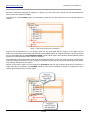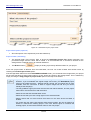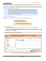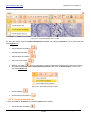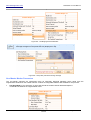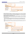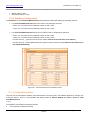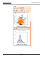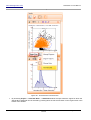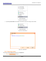
1
www.tissuegnostics.com
HistoQuest 3.0 User Manual
HistoQuest 3.0
User Manual
Internal
Page 1 of 351
www.tissuegnostics.com
HistoQuest 3.0 User Manual
Table of Contents
Table of Contents ................................................................................................................................................. 2
Disclaimers ........................................................................................................................................................... 5
Notices about symbols and labels on product ..................................................................................................... 6
1. Introduction ............................................................................................................................................................... 7
1.1. Purpose ............................................................................................................................................................. 7
1.2. Goals of the application ..................................................................................................................................... 7
1.3. Definitions, Acronyms and Abbreviations .......................................................................................................... 7
1.4. Conventions ....................................................................................................................................................... 9
2. Installing HistoQuest ...............................................................................................................................................11
2.1. Application Dependencies ...............................................................................................................................11
2.2. Windows 3.1 Installer for Windows XP SP2 ....................................................................................................11
2.3. NET Framework 2.0 Runtime ..........................................................................................................................11
2.4. Microsoft Visual C++ 2005 Redistributables ...................................................................................................11
2.5. Intel Performance Primitives 5.3 .....................................................................................................................12
2.6. MARX Dongle Drivers .....................................................................................................................................12
2.7. System Requirements .....................................................................................................................................12
2.7.1. Hardware Requirements ..........................................................................................................................12
2.7.2. Software Requirements ............................................................................................................................12
3. Starting HistoQuest .................................................................................................................................................14
3.1. Login Dialog .....................................................................................................................................................14
3.2. Startup window ................................................................................................................................................15
4. Projects ...................................................................................................................................................................17
4.1. Import TissueFAXS/HistoFAXS Project ..........................................................................................................17
4.1.1. Step 1: Choose the TissueFAXS/HistoFAXS Project ..............................................................................18
TMA Projects ......................................................................................................................................................31
4.1.2. Step 2: HistoQuest Project .......................................................................................................................37
4.1.3. Step 3: Choose Markers ..........................................................................................................................40
4.2. Import Folder ...................................................................................................................................................47
4.2.1. Step 1: Choose Folder .............................................................................................................................47
4.2.2. Step 2: HistoQuest Project .......................................................................................................................50
4.2.3. Step 3: Choose Markers ..........................................................................................................................52
4.3. Import Images from a Hamamatsu NanoZoomer File .....................................................................................53
4.3.1. Step 1: Choose Hamamatsu NanoZoomer file ........................................................................................54
4.3.2. Step 2: HistoQuest Project .......................................................................................................................56
4.3.3. Step 3: Choose Markers ..........................................................................................................................58
4.4. Import images from a Mirax file .......................................................................................................................60
4.4.1. Step 1: Choose Mirax file .........................................................................................................................60
4.4.2. Step 2: HistoQuest Project .......................................................................................................................63
4.4.3. Step 3: Choose Markers ..........................................................................................................................64
4.5. Open HistoQuest Project .................................................................................................................................66
4.6. Project Properties ............................................................................................................................................69
4.7. Finalize Analysis ..............................................................................................................................................72
4.8. TMA .................................................................................................................................................................73
5. Region Viewer.........................................................................................................................................................75
5.1. Navigator .........................................................................................................................................................75
5.2. Map ..................................................................................................................................................................77
5.3. Ruler ................................................................................................................................................................80
5.4. Scale Bar .........................................................................................................................................................81
5.5. Show Color RGB Button ..................................................................................................................................82
5.6. Excluding and removing FOVs (Flag Button) ..................................................................................................84
5.7. Shape Manipulation toolbar .............................................................................................................................86
5.8. Show/Hide Shape ............................................................................................................................................86
5.9. Edit Mode Button .............................................................................................................................................87
5.10. Analyze Button ..............................................................................................................................................87
5.11. View Raw Data Button ..................................................................................................................................87
5.12. Easy drawing tool ..........................................................................................................................................87
5.13. Options Button ...............................................................................................................................................89
Internal
Page 2 of 351
www.tissuegnostics.com
HistoQuest 3.0 User Manual
5.14. Project Items Properties Control ...................................................................................................................89
5.15. Images Compare Sets ...................................................................................................................................92
6. Project Items .........................................................................................................................................................101
6.1. Samples and ROIs ........................................................................................................................................101
6.1.1. Samples .................................................................................................................................................101
Sample Comments ...........................................................................................................................................105
Illumination Correction .....................................................................................................................................106
6.1.2. ROIs .......................................................................................................................................................108
ROI Comments.................................................................................................................................................120
Autodetect ROIs ...............................................................................................................................................121
6.1.3. Group of ROIs ........................................................................................................................................126
6.2. Annotations ....................................................................................................................................................138
6.2.1. Annotation Manipulation Toolbar ...........................................................................................................138
6.2.2. Creating Annotations ..............................................................................................................................139
6.2.3. Managing Annotations ...........................................................................................................................141
6.2.4. Edit Annotations .....................................................................................................................................143
6.3. Exclusion Areas .............................................................................................................................................148
6.4. Transform Shapes .........................................................................................................................................151
7. Compare Sets .......................................................................................................................................................154
7.1. Create Compare Sets ....................................................................................................................................154
7.2. Side-by-Side Diagrams .................................................................................................................................155
7.3. Overlay Diagrams ..........................................................................................................................................159
7.4. Managing Compare Sets ...............................................................................................................................164
7.5. Compare Sets Print Out Reports ...................................................................................................................169
8. Shapes Measurements .........................................................................................................................................171
9. Markers and Profiles .............................................................................................................................................172
9.1. Markers ..........................................................................................................................................................172
9.1.1. Add Marker .............................................................................................................................................174
9.1.2. Add Copy of Marker ...............................................................................................................................176
9.1.3. Rename Marker .....................................................................................................................................177
9.1.4. Copy Marker Parameters .......................................................................................................................178
9.1.5. Set as Nuclear Marker ...........................................................................................................................180
9.1.6. Remove Markers ....................................................................................................................................181
9.1.7. Manage Markers ....................................................................................................................................182
9.2. Profiles ...........................................................................................................................................................184
9.2.1. Save Marker Profile ................................................................................................................................185
9.2.2. Load Profile from Project........................................................................................................................185
9.2.3. Load Marker Profile ................................................................................................................................186
9.2.4. Manage Profiles .....................................................................................................................................187
10. Color Separation Methods ..................................................................................................................................190
10.1. Multiple Reference Shades .........................................................................................................................190
10.1.1. Shades .................................................................................................................................................190
10.2. Single Reference Shade .............................................................................................................................199
11. Segmentation Methods .......................................................................................................................................205
11.1. Changing Segmentation Method .................................................................................................................205
11.1.1. Configure Segmentation Method Parameters......................................................................................207
11.2. Various Shapes 1.0 .....................................................................................................................................208
11.2.1. Parameters ...........................................................................................................................................208
11.2.2. Diagrams Configuration .......................................................................................................................217
11.2.3. Raw Data Columns Configuration ........................................................................................................217
11.2.4. Statistics Configuration ........................................................................................................................217
11.3. Various Shapes 2.0 .....................................................................................................................................218
11.3.1. Parameters ...........................................................................................................................................219
11.3.2. Diagrams Configuration .......................................................................................................................229
11.3.3. Raw Data Columns Configuration ........................................................................................................229
11.3.4. Statistics Configuration ........................................................................................................................229
11.4. Total Area Measurements ...........................................................................................................................229
11.4.1. Parameters ...........................................................................................................................................229
11.4.2. Diagrams Configuration .......................................................................................................................230
Internal
Page 3 of 351
www.tissuegnostics.com
HistoQuest 3.0 User Manual
11.4.3. Raw Data Columns Configuration ........................................................................................................230
11.4.4. Statistics Configuration ........................................................................................................................231
11.5. Configurable statistics .................................................................................................................................231
12. Image Analysis....................................................................................................................................................233
12.1. Analysis .......................................................................................................................................................233
12.1.1. Sample Analysis ...................................................................................................................................233
12.1.2. ROI Analysis ........................................................................................................................................235
12.1.3. Toolbar Analyze Button ........................................................................................................................241
12.1.4. Group of ROIs Analysis ........................................................................................................................243
12.2. Task Manager ..............................................................................................................................................244
13. Analysis Results..................................................................................................................................................246
13.1. Image Results..............................................................................................................................................246
13.2. Raw Data .....................................................................................................................................................251
13.2.1. Exporting events ..................................................................................................................................260
13.2.2. View Event Data ...................................................................................................................................262
13.3. Diagrams .....................................................................................................................................................264
13.3.1. Scattergrams ........................................................................................................................................264
13.3.2. Histograms ...........................................................................................................................................280
13.3.3. Diagram Detail Window........................................................................................................................287
Manage Diagrams ............................................................................................................................................289
14. Forward and Backward Connection ...................................................................................................................299
14.1. Forward Connection ....................................................................................................................................301
14.2. Backward Connection .................................................................................................................................302
14.3. Backward Data ............................................................................................................................................302
14.3.1. Scattergrams ........................................................................................................................................302
14.3.2. Histograms ...........................................................................................................................................305
15. Manual Correction ..............................................................................................................................................307
16. Reports ...............................................................................................................................................................310
16.1. Statistics Report ..........................................................................................................................................310
16.2. Print Out ......................................................................................................................................................314
17. Menu Bar ............................................................................................................................................................322
17.1. File Menu .....................................................................................................................................................322
17.2. Project Menu ...............................................................................................................................................324
17.3. Tools Menu ..................................................................................................................................................326
17.3.1. Manage Diagrams ................................................................................................................................326
17.3.2. Manage Gates ......................................................................................................................................326
17.3.3. Statistics Report… ...............................................................................................................................326
17.3.4. Options… .............................................................................................................................................327
17.4. Help Menu ...................................................................................................................................................343
18. Modularization.....................................................................................................................................................345
19. Memory Issues....................................................................................................................................................349
20. References...................................................................................................... Fehler! Textmarke nicht definiert.
21. Document History ........................................................................................... Fehler! Textmarke nicht definiert.
22. Document Quality Assurance ......................................................................... Fehler! Textmarke nicht definiert.
Internal
Page 4 of 351
www.tissuegnostics.com
HistoQuest 3.0 User Manual
Disclaimers
1. TissueFAXSplus is a microscope-based cell analysis system for cells in cryocuts, paraffin sections and TMAs. It
consists of the software modules “TissueFAXS”, “TissueQuest“, and “HistoQuest“ and is used for acquisition of
images in the fluorescence and brightfield mode, for counting the number of positive and negative cells and for
quantification of staining intensities. TissueFAXSplus is used for the standardization of tissue analysis in
combination with immunohistochemical and immunofluorescence staining.
The system does not give any direct diagnosis and there is the possibility that the samples do not contain enough
information to give a clear diagnosis.
The results of the analysis are purely statistical values. Users must reevaluate images and likelihood of the
statistical data. Pure interpretation of statistical data is a high risk.
Observations:
- TissueFAXS is similar to TissueFAXSplus but is for fluorescence samples only and must not be used with
brightfield/immunohistochemical samples. TissueFAXS consists of the software modules “TissueFAXS“ and
“TissueQuest“.
- HistoFAXS is similar to TissueFAXSplus but is for brightfield/immunohistochemical samples only and must not
be used with fluorescence samples. HistoFAXS consists of the software modules “TissueFAXS“ and
“HistoQuest“.
2. Each and any product should be used only after training performed by TissueGnostics or authorized distributors
of TissueGnostics. A list of authorized distributors is available here:
http://www.tissuegnostics.com//index.php?load=xml/en/home/company/distributors.xml&lang=en
3. The names of actual companies and products mentioned herein may be the trademarks of their respective
owners.
4. In order to use HistoQuest application, it is essential for the users to have sufficient knowledge of PC and
Microsoft Windows operating system usage.
5. The information from this document is subject to changes without notice.
6. The information contained in this document is the proprietary and exclusive property of
TissueGnostics GmbH except as otherwise indicated. No part of this document, in whole or in part, may be
reproduced, stored, transmitted, or used for design purposes without the prior written permission of TissueGnostics
GmbH.
7. The information in this document is provided for informational purposes only.
8. TissueGnostics GmbH specifically disclaims all warranties, express or limited, including, but not limited, to the
implied warranties of merchantability and fitness for a particular purpose, except as provided for in a separate
software license agreement.
9. Copyright© 2006-2011 TissueGnostics™ GmbH. All rights reserved.
10. Release date of this document: 17 June 2011
11. Document version: 4.3
Internal
Page 5 of 351
www.tissuegnostics.com
HistoQuest 3.0 User Manual
Notices about symbols and labels on product
The following symbols appear on the labels of the product:
Figure 1 - Product labels
Serial number
WEEE symbol / separate disposal of
electrical and electronic equipment
CE mark
Manufacturer
Notice regarding anti-virus applications
•
All the TissueGnostics products are shipped with the Kaspersky Anti-Virus in order to ensure optimal
functionality.
•
Therefore TissueGnostics only guarantees for Kaspersky Anti-Virus to work with its products.
•
The user may decide to use other anti-virus software only upon own responsibility.
•
Any problem that arises due to other anti-virus software installed will void TissueGnostics
warranty and every support or service action required by the client in order to restore any of
TissueGnostics damaged instruments will be billed to the customer.
Internal
Page 6 of 351
www.tissuegnostics.com
HistoQuest 3.0 User Manual
1. Introduction
Introduction to histology
Histology is a fundamental basis both in routine diagnostics and pathology, as well as basic research. Over the
preceding decades, an ever increasing amount of specific molecular markers has been established, which help
pathologists, clinicians and researchers to appropriately characterize diseases and understand molecular
interdependencies. For such a characterization, however, a simple “look and conclude” investigation is not
sufficient. For many markers a positive/negative decision does not represent a qualified approach. Neither does a
“+”, “++”, “+++” estimation. Rather the question has to be addressed “how much” of a certain marker is present
“where” in cells and tissues.
Moreover, measurements of simultaneously determined markers, patterns and functions are required. In order to
optimally fit therapies to individual patient’s needs, specimens have to be analyzed for an entire set of markers
and/or marker combinations in an observer independent manner. In order to meet these requirements, computer
aided processing of histological samples is required.
1.1. Purpose
The purpose of this document is to help the user understand how HistoQuest works. It describes HistoQuest
software’s capabilities and it guides the user through the features of the application, in order to master all the
information required for an optimal usage.
The document covers: installation of the application, system requirements, main features.
In the next section you will read more about the goals of the application and its place in a larger system. You will
also understand the purpose and the advantages of this application.
1.2. Goals of the application
The HistoQuest software has been designed for cytometric analysis of tissue sections, including TMAs and biopsy
material, as well as cytological preparations.
The initial point of the process chain in tissue analysis using the HistoQuest software is importing of images to a
new project.
Analysis parameters for sophisticated image processing and pattern recognition algorithms have to be optimized
for your specific needs.
After optimization of analysis parameters, segmentation is done for all images in the project, which results in a set
of numerical data. These data are visualized in scattergrams and/or histograms and are subject to further
processing and, finally, statistical analysis.
1.3. Definitions, Acronyms and Abbreviations
Algorithm
A sequence of mathematically realized processing steps applied to an image or part of an image, with the aim to
improve image quality and to extract specific information or segment (identify) image objects.
What an algorithm might do:
1. Separate color images;
Internal
Page 7 of 351
www.tissuegnostics.com
HistoQuest 3.0 User Manual
2. Identify colored regions;
3. Discriminate background from specific cell objects;
4. Recognize individual cells (where does one cell end and neighboring cell begin);
5. Identify cytoplasmatic areas.
Analysis
An analysis is the process of identifying individual nuclei, cells, cellular compartments and other structures of
histological/pathological relevance, respectively. This operation is accomplished by applying the algorithms of the
HistoQuest software to the images of tissue sections.
Cutoff Value
A numerical parameter used as a threshold value in a scattergram, in order to distinguish between specific and
unspecific staining patterns, allowing determining positive and negative measure events.
Event
A data unit obtained by HistoQuest algorithms representing a quantum of information about a defined object
(nucleus, cell).
An event is identified by one or several image processing and pattern recognition algorithms. An event contains
data for all measurement parameters applied to a single image object.
Gate
A subset of events within a scattergram, selected by defining a region in a diagram.
Gates may have one of the following shapes: rectangular, elliptical and polygonal and contain any number of cells.
Gates may overlap each other and be combined or defined as mutually excluding.
Marker
A molecular labeling component (chemical or biological reagent; e.g. Hemalaun stain, antibody, genetic probe) that
allows the identification of defined cell types, tissue types, cellular or tissue compartments, cellular functions,
disease status, etc.
In HistoQuest, markers have colors picked from the images to be analyzed and also parameters for detection and
measurement masks.
Project
A set of tissue samples which are analyzed together, with the same parameter settings for the image analysis and
pattern recognition algorithms.
Quadrant Regions
Each scattergram is separated into four regions by its x- and y- cutoff values. The four quadrant regions are labeled
lower left (LL), upper left (UL), upper right (UR), and lower right (LR). As scattergrams are a means of
visualizing co-expressions of different markers (two in each scattergram) the quadrant regions define the four
possible combinations of positive and negative (i.e. above or below cutoff value) per marker:
1. LL: Marker X negative and Marker Y negative;
2. UL: Marker X negative and Marker Y positive;
3. UR: Marker X positive and Marker Y positive;
4. LR: Marker X positive and Marker Y negative.
Quadrant Statistics
Shows the following values according to the segmentation method:
For Various Shapes 1.0 and Various Shapes 2.0 with count used in computing the percents:
- X-Mean (i.e. mean value for the parameter shown on the x-axis);
- Y-Mean (i.e. mean value for the parameter shown on the y-axis);
Internal
Page 8 of 351
www.tissuegnostics.com
HistoQuest 3.0 User Manual
- Count (number of events in the respective unit: sample, gate, ROI, quadrant);
- Percentage (i.e. how many events are in the respective quadrant region relative to the total number of
events) for each of the four quadrant regions;
2
- No/mm (number of detected events per Area Measurement Unit).
For Various Shapes 1.0 and Various Shapes 2.0 with area of a marker used in computing the percents:
- X-Mean (i.e. mean value for the parameter shown on the x-axis);
- Y-Mean (i.e. mean value for the parameter shown on the y-axis);
- Total Area of […] (total area of chosen marker);
- Percent Area of […] (percent area of chosen marker relative to the total area of the marker);
- Percent Area of […]/Area Measurement Unit (percent area of chosen marker relative to the total area of
the Sample/ROI/Group).
For Total Area Measurements with count used in computing the percents:
- X-Sum (i.e. sum value for the parameter shown on the x-axis);
- Y-Sum (i.e. sum value for the parameter shown on the y-axis).
For Total Area Measurements with area of a marker used in computing the percents:
- X-Sum (i.e. sum value for the parameter shown on the x-axis);
- Y-Sum (i.e. sum value for the parameter shown on the y-axis);
- Percent Area of […] (percent area of chosen marker relative to the total area of the marker);
- Percent Area of […]/Area Measurement Unit (percent area of chosen marker relative to the total area of
the Sample/ROI/Group).
Scattergram
An x-/y- diagram showing two measurement parameters for all data units or a selection thereof in linear or
logarithmic scale.
Within the scattergram, cutoffs can be set in order to define a threshold for each measurement parameter.
Profile
A set of image analysis and image processing parameters used for proper identification of one or several specific
markers, that was stored to the hard disk and can be reloaded and reused for another sample at any time.
Field of View (FOV)
The area of a sample (tissue section) visible in the microscope and captured at one x-/y-/z- position on the slide
and with a given optical magnification. An image of one Field of View may contain several markers.
1.4. Conventions
In this section you can find listed and explained the conventions used throughout this manual.
Note(s): describes important features or instructions.
Tip(s): highlights features or hints that can help you save time or avoid difficulties.
Internal
Page 9 of 351
www.tissuegnostics.com
HistoQuest 3.0 User Manual
Caution(s): warns readers about possible damage to equipment or to data or about potential problems
in the outcome of what they are doing.
functional system.
Requirement(s): informs the user about the demands that must be met in order to have a fully
Italics: are used in order to highlight a title and also new or unfamiliar terms, usually at their first appearance in the
text.
Bold: are used in order to highlight important terms or to mark the names of the features/GUI elements throughout
the text of this manual.
→: the arrow indicates a menu choice. For example, choose “File → Save as template” means you have to
choose Save as template from the File menu.
Internal
Page 10 of 351
www.tissuegnostics.com
HistoQuest 3.0 User Manual
2. Installing HistoQuest
2.1. Application Dependencies
There are some special requirements concerning the installation of HistoQuest. You may check below for the
components required to be installed on your computer. It is recommended to have all these components installed
before you install the HistoQuest product.
Install them in any order, but make sure HistoQuest is the last one to be installed.
- HistoQuest software will not run and operate properly if any of the components below
is not installed on your HistoQuest workstation.
Installing software programs and Windows system components will require Administrator privileges on your
computer. You might need to ask for support at your IT department if you do not owe the rights to install software or
you don’t have sufficient IT knowledge.
2.2. Windows 3.1 Installer for Windows XP SP2
The Microsoft® Windows® Installer is an application installation and configuration service.
2.3. NET Framework 2.0 Runtime
The HistoQuest product is built over the version 2.0 of .NET Framework which can be also found at the Microsoft
official website.
The Microsoft .NET Framework version 2.0 redistributable package installs the .NET Framework runtime and
associated files required to run applications developed to target the .NET Framework v2.0.
It is recommended to install the latest service pack available for the Microsoft .NET Framework version 2.0.
For further information about this package please visit the Microsoft homepage.
2.4. Microsoft Visual C++ 2005 Redistributables
The Microsoft Visual C++ 2005 Redistributable Package (x86) installs runtime components of Visual C++ Libraries
required to run applications developed with Visual C++ on a computer.
HistoQuest contains modules that were developed with Visual C++, so this redistributables kit is required.
- If you have installed previous pre-release versions of Visual C++ 2005 or Visual Studio
2005, such as Beta 1, Beta 2 or Community Technical Preview (CTP) builds, then you
must uninstall these versions via Add/Remove Programs in Control Panel before
installing the final released version.
For further information about this package please visit the Microsoft homepage.
Internal
Page 11 of 351
www.tissuegnostics.com
HistoQuest 3.0 User Manual
2.5. Intel Performance Primitives 5.3
Intel® Integrated Performance Primitives (Intel® IPP) is a software library that increases performance of Intel's
latest microprocessors. Incorporating these functions into the HistoQuest software will ensure that the potential of
your Intel-based PC can be fully exploited for analysis of your samples.
2.6. MARX Dongle Drivers
HistoQuest uses a hardware based security solution from MARX Software Security. When purchasing
HistoQuest, you will also receive an USB dongle that must be inserted in an USB port. In order to successfully use
the dongle you must install the corresponding driver for the operating system.
2.7. System Requirements
2.7.1. Hardware Requirements
Minimum
• Intel Pentium 4 Processor - 3 GHz
• 1 GB
• USB-Port (for dongle)
• 100 GB available hard disk space
• Single monitor system with a resolution of 1024x768
Recommended
•
•
•
•
•
•
Intel Core2Duo Quad Processor - 3 GHz (or more)
4 GB RAM
Internet connection
USB-Port (for dongle)
1000 GB hard disk space for storing your projects
Dual monitor system with a resolution of 1280x1024 (or higher)
2.7.2. Software Requirements
•
•
•
•
•
•
Windows 7 x32 (Recommended)
Windows 7 x64
Windows XP
Windows Vista x32
Windows Vista x64
Windows 2000
- By default, HistoQuest needs to be run by a user member of the Administrators group.
In this case, all users will share some settings (e.g. institution data, system data,
users).
- HistoQuest can be also run by a user member of the Users group, in which case
every user will have its own settings.
- Please contact your Support team in order to get the desired configuration for your
workstation.
Once all the components are successfully installed, the application is ready to be used.
- TissueGnostics provides a set-up application that installs HistoQuest and all its
dependencies. For more information please contact your support team.
Internal
Page 12 of 351
www.tissuegnostics.com
HistoQuest 3.0 User Manual
Notice regarding virtual machines
TissueGnostics software is not meant to work on virtual machines. Also, TissueGnostics does not offer support for
these configurations, as the software directly uses advanced CPU features and therefore any third layer between
the software and the CPU will affect performance and might affect the results of the analysis in an unpredictable
way.
Internal
Page 13 of 351
www.tissuegnostics.com
HistoQuest 3.0 User Manual
3. Starting HistoQuest
3.1. Login Dialog
After starting the application, a login dialog will appear. In order to login to HistoQuest, you must enter a username
into the User Name field and type the proper password into the Password field.
Press Login in order to be authentified.
If the username and password are correct, the login dialog will close and you can start using the application.
Otherwise, the application will prompt again for a valid username and password combination.
If you press Cancel, the login dialog and the application will close.
The login dialog is used to restrict access to the application. There is one Administrator and any number of users,
who may be managed when the Administrator is logged in (for more details please see Chapter 17.3.4).
Figure 2 - Login Panel
Internal
Page 14 of 351
www.tissuegnostics.com
HistoQuest 3.0 User Manual
Loading HistoQuest takes several seconds. During this process of program initialization, a splash screen is
displayed until the application is loaded and ready to be used.
Figure 3 - Splash Screen
3.2. Startup window
After the splash screen disappears, the main window of the application is shown. In order to use the full
HistoQuest functionality, either a new project must be created or an existing one must be loaded. Having a project
is mandatory, otherwise the user is not able to select any images for the analysis, nor choose any markers and
perform analysis. All this information is embedded in a project.
Only one project can be opened at a time and there are four available possibilities to perform this operation:
Internal
Page 15 of 351
www.tissuegnostics.com
HistoQuest 3.0 User Manual
Figure 4 - Start Window
•
•
To create a new project, the user must select Import TissueFAXS Project/HistoFAXS, Import Folder,
Import Hamamatsu NanoZoomer or Import images from a Mirax file from the start-up window. A proper
wizard will appear and the user will be prompted to enter the project data. He can also start these wizards
from the File menu. For more details please see Chapter 4.
To open an existing project, the user will choose Open Existing Project from the start-up window or the
Open… option from the File menu or press the Open button from the main toolbar (
).
- In order to open an existing project, you can also use the CTRL + O key combination
from your keyboard.
- When creating a new project, the first sample is automatically loaded in the main
image viewer.
Internal
Page 16 of 351
www.tissuegnostics.com
HistoQuest 3.0 User Manual
4. Projects
- When creating a project, if the name of the path exceeds Windows limits, the user will
receive a warning message. This means the path to the project is too long.
- Also, the path to the images must not exceed above mentioned limits.
- Regarding projects storage: Avoid storing projects on Desktop, My Documents, or in
any other folder located on the system drive (usually C). If the drive is nearly at its full
capacity, the system might behave erratically or even stop working if the drive
completely runs out of space. Usually, systems delivered by TissueGnostics have a
dedicated storage medium for projects; it is advisable to use it in order to increase
TissueGnostics products performance and avoid issues with low disk space. Also in
case the system needs to be reinstalled (virus infection, system files being deleted)
you might lose data located on the system drive.
4.1. Import TissueFAXS/HistoFAXS Project
The TissueFAXS and HistoQuest management and acquisition software applications are powerful tools. They are
the core of TissueGnostics’ microscope-based cell analysis systems for cells in tissue sections, culture monolayers,
cytospin preparations and cell smears.
An existing TissueFAXS-brightfield or a HistoFAXS project file may be used to create a HistoQuest project. This
operation is realized by importing a project from TissueFAXS/HistoFAXS into HistoQuest. To guide the user
through this process, we provide the Import TissueFAXS Project Wizard.
In
(
order
to
import
a
TissueFAXS/HistoFAXS
project,
press
the
TissueFAXS/HistoFAXS
button
) or choose from the menu File → Import → TissueFAXS/HistoFAXS…:
Internal
Page 17 of 351
www.tissuegnostics.com
HistoQuest 3.0 User Manual
Figure 5 - Import TissueFAXS/HistoFAXS project
- The TissueFAXS software provides stitch support and HistoQuest can open and
properly display samples with stitch applied. In the case of a project with stitch, in
project properties are displayed the sizes of the original FOVs, not the crop size.
4.1.1. Step 1: Choose the TissueFAXS/HistoFAXS Project
Start by selecting a TissueFAXS/HistoFAXS project file to be imported to HistoQuest. This operation can be done
by typing the path to the project file or by browsing for it.
- The user should ensure that the selected file exists at that location and that he has
enough rights on it, otherwise he won’t be able to use it (an error message should
appear in this case). It is recommended choosing a local drive, both for ensuring
performance and avoiding unpredictable errors.
- For TissueFAXS versions compatible with your HistoQuest version please contact
your TissueGnostics support team.
Internal
Page 18 of 351
www.tissuegnostics.com
HistoQuest 3.0 User Manual
Figure 6 - Import TissueFAXS/HistoFAXS Project - Step 1
- If the project to be opened in HistoQuest is simultaneously opened in TissueFAXS or
it has been created with an unsupported TissueFAXS version, an error message will
appear.
Internal
Page 19 of 351
www.tissuegnostics.com
HistoQuest 3.0 User Manual
Figure 7 - Opening TissueFAXS project - error message
- The last imported TissueFAXS/HistoFAXS project file will be remembered (if any).
- The TissueFAXS/HistoFAXS project to be imported in HistoQuest must not be
opened at the same time in TissueFAXS/HistoFAXS management and acquisition
software.
- Without license, the user won’t be able to create a new project from a
TissueFAXS/HistoFAXS project. Also, he won’t be able to add sample(s)
from a TissueFAXS/HistoFAXS project.
Choose Regions
The analysis in HistoQuest is performed on tissue samples. Images of your samples (virtual samples) can be
obtained by importing a TissueFAXS/HistoFAXS acquisition project.
Internal
Page 20 of 351
www.tissuegnostics.com
HistoQuest 3.0 User Manual
Figure 8 - Import TissueFAXS/HistoFAXS Project - Step 2
You can also see which regions of the TissueFAXS/HistoFAXS project can be imported in HistoQuest and select
the desired ones. You can find here the description for:
•
•
•
The experiment: number of slides, regions, TMA blocks, TMA spots and comments (if any).
The slide: number of regions and comments (if any). For TMA blocks, the number of spots will be
mentioned.
The region: acquisition status, FOV matrix size, number of images, objective used for acquisition, FOV
size, and comments (if any).
On the right side of the panel, there is a preview image of the slide.
- If a TissueFAXS project was previewed with illumination correction, when importing
the respective project in HistoQuest the preview image of the slide in the wizard will
be shown with illumination correction.
- If a TissueFAXS project was acquired with illumination correction, when importing the
respective project in HistoQuest the samples will already have applied illumination
correction.
Select Regions section
The TissueFAXS/ HistoFAXS project file is not enough to run analysis in HistoQuest; the user must also provide
the acquired images. TissueFAXS/HistoFAXS regions cannot be imported without the stored image files.
Internal
Page 21 of 351
www.tissuegnostics.com
HistoQuest 3.0 User Manual
Moreover, rather than analyzing all samples in a project, you may select which samples should be included from
the items that are valid and available.
The images of a TissueFAXS project are structured in slides and for each slide there can be several regions of
interest.
Figure 9 - Regions to be imported to HistoQuest
Regions can be selected one by one (simply check the box associated with the region), by the slide they are
defined on (check the box associated with the slide and available regions of it will be selected) or by project (check
the box associated with the TissueFAXS/HistoFAXS project and all regions from all slides will be selected). Slides
that do not contain acquired regions cannot be selected.
This page also provides descriptions of all items of the imported project. A user can check if a region was acquired,
how many images it contains, how many regions are defined on each slide and how many slides are in the project,
as previously mentioned in this chapter.
Maybe not all shown regions can be imported to HistoQuest and this step specifies those that are allowed. A
region that was not acquired in TissueFAXS cannot be used, so this limitation is shown by a special font and a
special representative image, as seen below.
Internal
Page 22 of 351
www.tissuegnostics.com
HistoQuest 3.0 User Manual
Figure 10 - Items description
A preview of each region and slide is displayed in the right part of the window, if available. The regions that are
listed in red are not acquired.
Select acquired regions section
This section gives three selection options:
Figure 11 - Select acquired regions section
•
Custom Select: by checking this option, the user will be able to manually select the desired items in the
Select Region section.
•
Select Only Standard Regions: by checking this option, only standard regions will be selected.
•
Select Only Time Regions: by checking this option, only regions acquired with time lapse will be selected.
- If the check mark is set on Select Only Standard Regions or Select Only Time
Regions and the user manually modifies the selection in Select Regions section, the
check mark will automatically move on Custom Select.
Depending on the number of time lapse regions present in the Select Regions section, you can choose the way
they are displayed by using the two buttons placed below the Select acquired regions section:
•
Expand Time Regions: will expand all time lapse regions in the Select Regions section.
•
Collapse Time Regions: will collapse all time lapse regions in the Select Regions section.
Internal
Page 23 of 351
www.tissuegnostics.com
HistoQuest 3.0 User Manual
Figure 12 - Expand / Collapse Time Regions buttons
Description section
Depending on the type of item selected in the Select Region section, a different description will be displayed in the
Description section (see image below).
Internal
Page 24 of 351
www.tissuegnostics.com
HistoQuest 3.0 User Manual
Figure 13 - Description section
Import TissueFAXS/HistoFAXS regions
When Import TissueFAXS/HistoFAXS regions option is checked, the imported regions from
TissueFAXS/HistoFAXS will keep the original names and will be treated as ROIs, preserving the same shape as
in TissueFAXS. If this option remains unchecked, only the sample (without the ROIs) will be imported.
Internal
Page 25 of 351
www.tissuegnostics.com
HistoQuest 3.0 User Manual
Figure 14 - TissueFAXS/HistoFAXS Region (as shown in TissueFAXS software)
Figure 15 - HistoQuest Region of Interest
Internal
Page 26 of 351
www.tissuegnostics.com
HistoQuest 3.0 User Manual
Import TissueFAXS/HistoFAXS logical groups
When Import TissueFAXS/HistoFAXS logical groups option is checked, the HistoQuest project will import them.
The imported logical groups from the acquisition module will keep the original name and will be treated as groups
of ROIs.
- This option is available only for TMA projects. The Import TissueFAXS/HistoFAXS
logical groups option is available only if previously checking Import
TissueFAXS/HistoFAXS regions option. Different TMA spots belonging to separate
TMA blocks could be gathered in the same group.
Figure 16 - Import TissueFAXS/HistoFAXS logical groups
When Import TissueFAXS/HistoFAXS subregions option is checked, the HistoQuest project will open them. The
imported subregions from the acquisition module will keep the original name and will be treated as ROIs.
Internal
Page 27 of 351
www.tissuegnostics.com
HistoQuest 3.0 User Manual
Figure 17 -TissueFAXS/HistoFAXS Categories
Internal
Page 28 of 351
www.tissuegnostics.com
HistoQuest 3.0 User Manual
Figure 18 - HistoQuest Categories
Create Group of ROIs from TissueFAXS/HistoFAXS categories
When Create Group of ROIs from TissueFAXS/HistoFAXS categories option is checked, the HistoQuest
project will open them. The imported categories from the acquisition module will keep the original name and will be
treated as groups of ROIs.
Internal
Page 29 of 351
www.tissuegnostics.com
HistoQuest 3.0 User Manual
Figure 19 - HistoQuest group of ROIs from TissueFAXS/HistoFAXS categories (a)
Figure 20 - HistoQuest group of ROIs from TissueFAXS/HistoFAXS categories (b)
Internal
Page 30 of 351
www.tissuegnostics.com
HistoQuest 3.0 User Manual
Figure 21 - HistoQuest group of ROIs from TissueFAXS/HistoFAXS categories (c)
Figure 22 - HistoQuest group of ROIs from TissueFAXS/HistoFAXS categories (d)
TMA Projects
For TMA
projects, the user can create samples for:
Internal
Page 31 of 351
www.tissuegnostics.com
•
•
•
HistoQuest 3.0 User Manual
Each TMA spot;
Each TMA block;
Each TMA slide.
For the Create Sample for each TMA spot, HistoQuest will create a sample from each TMA spot in the project.
Figure 23 - Create Sample for each TMA spot
Figure 24 - TMA spot in TissueFAXS
Internal
Page 32 of 351
www.tissuegnostics.com
HistoQuest 3.0 User Manual
Figure 25 -TMA spot in HistoQuest
For the Create Sample for each TMA block, HistoQuest will create a sample from each TMA block in the project.
Figure 26 - Create Sample for each TMA block
Internal
Page 33 of 351
www.tissuegnostics.com
HistoQuest 3.0 User Manual
Figure 27 - TMA block in TissueFAXS
Figure 28 -TMA block in HistoQuest
Internal
Page 34 of 351
www.tissuegnostics.com
HistoQuest 3.0 User Manual
Figure 29 - Create Sample for each TMA slide
Figure 30 -TMA slide in TissueFAXS
Internal
Page 35 of 351
www.tissuegnostics.com
HistoQuest 3.0 User Manual
Figure 31 -TMA slide in HistoQuest
If the acquisition was realized with different objectives for different regions, the user will be asked if he wants to
open the regions acquired with the objective value of the first region in the project. In this situation, the user has the
possibility to manually choose the regions acquired with the same objective.
Figure 32 - Message Box for Different Objectives
- When the analysis is started, identical image processing and object segmentation
steps are applied to all samples. You cannot analyze samples acquired at different
magnification in a single analysis. You can change analysis parameters for individual
samples and perform the analysis only for those, but this will cause inconsistency
between analysis parameters and obtained data (results)! Hence, it is HIGHLY
RECOMMENDED to analyze samples acquired at different magnification in different
HistoQuest analysis projects.
Internal
Page 36 of 351
www.tissuegnostics.com
HistoQuest 3.0 User Manual
- For creating a sample from block or slide, a TMA license is required!
In the lower part of the Choose Regions dialog, a message regarding the status of the selected samples will
always be displayed:
1. When you have between one and ten samples: “Note: Your project will have 5 samples!”
2. When no sample is selected: “Warning: You must select at least one region!”
3. When you have more than ten samples: “Warning: Your project will have “x” samples!”
Figure 33 - Status of the selected samples: examples of displayed messages
4.1.2. Step 2: HistoQuest Project
To perform this step of the Import TissueFAXS/HistoFAXS project wizard, the user must provide identification
information for the HistoQuest project he is about to create.
HistoQuest Project step of the wizard has two tabs: Basic Settings and Advanced Settings.
Basic Settings
Internal
Page 37 of 351
www.tissuegnostics.com
HistoQuest 3.0 User Manual
Figure 34 - Import TissueFAXS/HistoFAXS Project - Step 3: Basic Settings
Project Name (mandatory)
•
Name of the project: it must contain minimum 1 character, maximum 50 characters. It must also not contain
any forbidden characters: " < > | : * ? \ /.The corresponding HistoQuest project file will have this name and
it will be stored in the folder selected in the first step of the wizard. The default name of the project is the
name of the import folder.
Internal
Page 38 of 351
www.tissuegnostics.com
HistoQuest 3.0 User Manual
Figure 35 - HistoQuest Project: project name
Project Description (optional)
•
Short description of the experiment (max 255 characters).
Project Folder (mandatory)
•
The storage folder of the project. Here is where the HistoQuest Project File (hiqproj extension), the
processed images and the cache will be saved. It is recommended not to choose as location for the
storage folder a mapped drive or an external hard drive.
•
The Browse button (
) helps you finding a previously defined location for your project.
If the new project folder is different from the initial folder, the user can create a folder with another name by
checking the Create Project Folder option.
If the storage folder differs from the TissueFAXS/HistoFAXS folder, you can decide if the images from your project
will be used remaining at their initial location or if they should be copied in the storage folder. This is realized by
simply checking the Copy images to project folder option in this step of the wizard.
- If you decide to leave images at their initial storage location, you will save space.
However, if you move/delete the original image source files, your HistoQuest project
might not be usable anymore – data will remain, though, but, as images are no more
available, also the connection of data to original images will fail and you cannot
reanalyze the sample(s).
- The fully qualified .hiqproj file name must be less than 260 characters, and the project
folder name must be less than 248 characters.
- Please ensure that the selected folder exists.
- Please ensure that you have enough rights on the selected folder.
- Please ensure that you have enough free space on the drive where the folder is
located.
- If a project with the same name already exists at this location, the user is asked if he
wishes to overwrite the existing project. If the user doesn’t agree to overwrite the
existing project, he must select another name for the new project.
Internal
Page 39 of 351
www.tissuegnostics.com
HistoQuest 3.0 User Manual
- If the storage folder is the same as the TissueFAXS/HistoFAXS project folder, then
the newly created project will be automatically saved in this folder and all temporary
files will also be stored at this location. To save the HistoQuest project at another
location, a different storage folder must be specified.
Advanced Settings
Figure 36 - Import TissueFAXS/HistoFAXS Project - Step 3: Advanced Settings
FOV Size
The user has more possibilities to enter the size of the FOV. For more details, please see Chapter 4.6.
Objective
The Objective value can not be modified; it is defined by TissueFAXS/HistoFAXS and it just serves for your
information. Starting from this value, the image will proportionally increase or decrease its size when the other
objective values are used.
4.1.3. Step 3: Choose Markers
Internal
Page 40 of 351
www.tissuegnostics.com
HistoQuest 3.0 User Manual
Markers (like Hematoxylin stain, antibody stain) are used for the identification of defined cell types, tissue types,
cellular or tissue compartments, cellular functions, disease status, etc. In HistoQuest, markers are represented by
a name and a set of parameters, depending on the Color Separation method and the Segmentation Method.
In this step, the user can choose the markers to be used in the current HistoQuest project.
To analyze the images provided, the HistoQuest product needs to have markers parameters set. A set of
completely defined markers can be saved for further use, obtaining what we call a profile.
Figure 37 - Import TissueFAXS/HistoFAXS project wizard - Step 4
When choosing the markers for the current project, the user has more options:
•
An existing profile (set of markers) can be loaded in order to be used in this project. This operation can be
done by clicking the Load Profile button (
). You will be able to see the markers from the
selected profile in the list of currently chosen markers, the segmentation method, the color separation
method and the strategy for events in ROIs.
- You can also use a profile from an existing project.
).
•
Existing markers can also be added one by one, by clicking the Add Marker button (
This way, only the name of the marker is loaded (the parameters have to be defined later).
•
A new marker can be added to the project, also by clicking the Add Marker button (
).
This marker will only have a name and you will have to choose its parameters later in order to use it.
Internal
Page 41 of 351
www.tissuegnostics.com
HistoQuest 3.0 User Manual
The markers already added (as described above) can also be removed one by one (by pressing
all at the same time (by pressing
available in the list.
) or
).These two options are available only if at least one marker is
After specifying the markers that will be used in the current project, the user has to pick a main marker (master
marker). The wizard cannot move to the next step until one of the available markers is chosen as master marker.
This is realized by simply checking the Is Master option corresponding to a marker.
The user will be able to choose:
•
•
•
Segmentation Method;
Strategy for events in ROI;
Color Separation Method.
- When loading a profile, the following buttons are disabled:
,
. However, if the markers from the loaded profile are not suitable, you
can press
of markers manually.
button in order to remove them, and then add a new set
Load Profile
A profile is a set of markers defined at an earlier occasion. A profile also contains information about the
segmentation method, the color separation method, the description of the markers and the segmentation method
parameters.
A profile created and saved in a HistoQuest project can be used for another project. This operation can be
realized when creating a project, in the Choose markers step of the wizard (
).
A list of the available profiles is presented to the user. The information available for each profile contains: the
segmentation method, the markers and their type (master or non-master).
To load a profile, simply select it from the list and then press the Ok button.
Figure 38 - Select Profile Dialog
Internal
Page 42 of 351
www.tissuegnostics.com
HistoQuest 3.0 User Manual
This method of choosing markers for a HistoQuest project can be combined with the other two available methods.
If the project to be created already contains chosen markers, they will be removed. If a profile was already loaded,
other markers (existing or new) can be added.
- Loading a profile (or loading a profile from an existing project) changes the current
segmentation method, color separation method and the strategy for events in ROIs.
- If choosing Load Profile, no other marker can be added to the profile’s configuration.
- If a profile is loaded, the markers, the segmentation method and the color separation
method cannot be changed from here.
Load Profile from Existing Project
HistoQuest gives the possibility to use a profile from another project that already exists.
Figure 39 - Load Profile from Existing Project - dropdown box
There are two possibilities:
•
Load Profile from Existing Project: choose this option to use a profile from an existing project;
•
Load Profile and Diagrams from Existing Project: when you import only the profile, the newly created
project will have its diagrams set by default. If you wish, you can choose to load a profile and also the
diagrams from an existing project.
Choose one of these two options, then use the browser in order to select the project that contains desired profile
(and diagrams) and load it by pressing Open button.
Figure 40 - Load Profile from Existing Project: browsing for the project
Internal
Page 43 of 351
www.tissuegnostics.com
HistoQuest 3.0 User Manual
- Load Profile from Existing Project or Load Profile and Diagrams from Existing
Project options can be activated only when creating the project; you will not be able to
use them once the project was already created.
- The diagrams will be imported from the first sample of the selected project.
- Load Profile from Existing Project and Load Profile and Diagrams from
Existing Project options require a license!
- Load Profile requires a license for Load Marker Profile or Save Marker
Profile!
Add Marker
In any new HistoQuest project, the user can operate with one of the existing markers, but he can also create a
new marker.
•
To add a new marker, press Add Marker button, then type a name and, optionally, a description. After the
creation of the project, the respective marker will receive the color separation method, the segmentation
method and the strategy for events in ROI properties.
Figure 41 - Add Marker Dialog
- The name is mandatory.
- The name must not coincide with the name of an existing marker.
- Please ensure that the name provided for the marker is valid (it does not contain any
unaccepted characters: " < > |: * ? \ /).
•
To add existing markers, press Add Marker button, then choose desired marker from the list available in
the dropdown box and press Enter key.
Internal
Page 44 of 351
www.tissuegnostics.com
HistoQuest 3.0 User Manual
Figure 42 - Select Existing Markers
Decide which marker should be used for cell identification (Master Marker)
The wizard asks which marker should be selected as master marker (nuclear marker). It is always the master
marker that has to be used for primary cell identification in all current algorithms. The appropriate box must be
checked.
Figure 43 - Select Master Marker dialog
If there is no selected master marker, the user will receive a message as in the dialog below:
Figure 44 - Select Master Marker - Message box
Internal
Page 45 of 351
www.tissuegnostics.com
HistoQuest 3.0 User Manual
- You may leave this field Currently chosen markers empty and select the markers
later in the Markers manipulation menu of the detail window. While the project is
loaded, a progress bar will appear.
- Add existing or new marker means that the name of a marker is used, only. To obtain
a marker that includes parameters, choose Load Profile.
After choosing the markers, the wizard is ready to create the HistoQuest project.
Figure 45 - Creating HistoQuest Project progress bar
By pressing the Cancel button (
) from the progress bar, the following message will appear:
Figure 46 - Creating HistoQuest Project canceling message
A TissueFAXS/HistoFAXS project can be added to a project by pressing the Add Samples from button
(
displayed menu:
) from the main window toolbar, then choose the TissueFAXS/HistoFAXS option from the
Figure 47 - Add TissueFAXS/HistoFAXS project
The same wizard will appear, but the values from step 3 and 4 cannot be modified.
Internal
Page 46 of 351
www.tissuegnostics.com
HistoQuest 3.0 User Manual
4.2. Import Folder
This 3-step wizard will guide the user through the process of creating a new HistoQuest project from an existing
folder. This option should be used if the samples have not been acquired by TissueFAXS/HistoFAXS.
- The special HistoQuest features for Tissue Microarrays (TMAs) handling are only
available for TissueFAXS projects; hence the Import Folder option cannot be used
for a TMA project.
4.2.1. Step 1: Choose Folder
At this point, the storage folder for the images to be imported must be selected. The newly created project will
contain all the images located in this folder.
In order to import a Folder, press the Folder button (
File → Import → Folder…:
) or choose from the menu
Figure 48 - Import Folder
Choose Images step of the wizard has two tabs: Basic settings and Advanced Settings.
Basic Settings
Internal
Page 47 of 351
www.tissuegnostics.com
HistoQuest 3.0 User Manual
Figure 49 - Import Folder Wizard - Step 1: Basic Settings
•
To filter the files from the selected folder, the user should use their extensions or a file naming pattern.
•
To select the project’s import folder, the user can simply type its path or press Browse button (
for the desired folder.
- The user should ensure that the selected folder exists and that he has enough rights
on it, otherwise he won’t be able to use it (in this case, an error message should
appear). If a problem occurs while reading the folder, HistoQuest will display a
message box like the one below.
Figure 50 - Message Box
- The last imported folder should be remembered (if any).
Internal
Page 48 of 351
)
www.tissuegnostics.com
HistoQuest 3.0 User Manual
•
From the listed images, check the ones you wish to import.
•
On the right side of the dialog, you have a preview of the currently selected image.
•
Add Subfolder Images: if you mark this checkbox, HistoQuest will import images from multiple folders.
From the listed subfolder images, check the ones you wish to import. For each subfolder containing images
and belonging to a folder, a sample will be created. This option is available only for projects from folders.
•
Exclude HistoQuest generated folder (Exclude _hiqtmp folder): mark this checkbox in order to exclude
HistoQuest generated folder(s) from your new project.
Figure 51 - Add Subfolder Images option
Advanced Settings
Internal
Page 49 of 351
www.tissuegnostics.com
HistoQuest 3.0 User Manual
Figure 52 - Import Folder Wizard - Step 1: Advanced Settings
You can select what type of images will be imported by using the extension based filter available in the Advanced
Settings tab. In the Images Filtering list, mark the checkboxes corresponding to the desired extensions.
- All image files within a single folder will be considered as belonging to the same
sample! If you have images that belong to different samples you have two options:
1. Create ROIs including only those FOVs, which belong to the same sample (see
Chapter 6.1 for details). ROIs and/or groups of ROIs will represent your individual
sample.
2. HistoQuest allows you to add more samples by importing images from folders after
the project has been created. For more details please see Chapter 6.1.1.
- The images must have three channels and the same size (the maximum size of a FOV
should not overpass 3200x2400).
4.2.2. Step 2: HistoQuest Project
This step is identical to the second step of the Import TissueFAXS/HistoFAXS project Wizard, having a Basic
Settings tab and an Advanced Settings tab. Since it is used to provide information about the HistoQuest project
that will be created (project name, project description and storage folder), any kind of project may be chosen, as
the functionality will be the same. For more information, please see Chapter 4.1.2 of this document.
Internal
Page 50 of 351
www.tissuegnostics.com
HistoQuest 3.0 User Manual
Figure 53 - Import Folder Wizard - Step 2: Basic Settings
To choose a new location for your project, use the Browse button. You can optionally add a description of the
project.
If the new project folder is different from the import folder, the user can create a folder with another name by
checking the Create Project Folder option.
If the storage folder differs from the import folder, you can decide if the images from your project will be used
remaining at their initial location or if they should be copied in the storage folder. This is realized by simply checking
the Copy images to project folder option in this step of the wizard.
- If you decide to leave images at their initial storage location, you will save space.
However, if you move/delete the original image source files, your HistoQuest project
might not be usable anymore – data will remain, though, but, as images are no more
available, also the connection of data to original images will fail and you cannot
reanalyze the sample(s).
- The fully qualified .hiqproj file name must be less than 260 characters, and the project
folder name must be less than 248 characters.
Internal
Page 51 of 351
www.tissuegnostics.com
HistoQuest 3.0 User Manual
Figure 54 - Import Folder Wizard - Step 2: Advanced Settings
The user has three possibilities to enter the size of the FOV (for more information, please see Chapter 4.1.2 of this
document).
The Objective value can also be modified by the user.
4.2.3. Step 3: Choose Markers
All HistoQuest projects must have a set of defined markers in order to analyze the provided images. This step is
identical to the fourth step of the Import TissueFAXS/HistoFAXS project wizard and it is used to choose the
markers for the current project. For a more detailed explanation see Chapter 4.1.3. of this document.
The user will be able to choose:
•
•
•
Segmentation Method;
Strategy for events in ROI;
Color Separation Method.
- If the user loads a profile, the segmentation method and the color separation method
cannot be changed. By removing all markers (by pressing Remove All Markers
button), the user will be able again to choose for the project any marker he wants.
Internal
Page 52 of 351
www.tissuegnostics.com
HistoQuest 3.0 User Manual
Figure 55 - Import Folder - Choose Markers
A Folder can be added to a project by pressing the Add Samples from button (
main window toolbar, then choose the Folder option from the displayed menu:
) from the
Figure 56 - Add Folder
The same wizard will appear, but the values from step 2 and 3 cannot be modified.
4.3. Import Images from a Hamamatsu NanoZoomer File
In order to import a Hamamatsu NanoZoomer file, press the Hamamatsu NanoZoomer
(
button
) or choose from the menu File → Import → NanoZoomer File…:
Internal
Page 53 of 351
www.tissuegnostics.com
HistoQuest 3.0 User Manual
Figure 57 - Import Hamamatsu NanoZoomer file
4.3.1. Step 1: Choose Hamamatsu NanoZoomer file
The Import from Hamamatsu NanoZoomer wizard will appear:
Figure 58 - Import from Hamamatsu NanoZoomer - Step 1 (a)
Internal
Page 54 of 351
www.tissuegnostics.com
Then, choose Browse (
HistoQuest 3.0 User Manual
) and select a NDPI file, then press Open:
Figure 59 - Import from Hamamatsu NanoZoomer - browser
- The user must choose a brightfield experiment acquired by a Hamamatsu
NanoZoomer instrument.
Internal
Page 55 of 351
www.tissuegnostics.com
HistoQuest 3.0 User Manual
Figure 60 - Import from Hamamatsu NanoZoomer - Step 1 (b)
At this point, the following data are available:
•
•
•
•
•
Image Map: the preview of the region as it is stored in NDPI file;
Width / Height: the width and the height of the sample in millimeters, with two decimals, as displayed by
Hamamatsu NanoZoomer;
Image Size: the desired FOV size in pixels (the recommended value is 1600x1200);
Image Format: the recommended format is JPG;
Z Position: the position to use from the Z-stack. If there is only one Z position, the spin edit will only have
the value 0 (zero). If the image has a single focus plan, the Z Position from the wizard will be disabled.
Now press Next.
4.3.2. Step 2: HistoQuest Project
This is the same Project Info dialog as in the wizards for importing a TissueFAXS/HistoFAXS project or an image,
including Basic and Advanced Settings. Default values are filled for Project Name and Project Folder. If the
Project Folder does not exist, the user will be asked if he wants to create it.
Internal
Page 56 of 351
www.tissuegnostics.com
HistoQuest 3.0 User Manual
Figure 61 - Import from Hamamatsu NanoZoomer - Step 2: Basic Settings
If you do not want to use the default project folder provided by HistoQuest, you can add the project name you
desire and HistoQuest will create this project folder if you check Create Project Folder.
- The fully qualified .hiqproj file name must be less than 260 characters, and the project
folder name must be less than 248 characters.
If the storage folder differs from the import folder, you can decide if the images from your project will be used
remaining at their initial location or if they should be copied in the storage folder. This is realized by simply checking
the Copy images to project folder option in this step of the wizard.
- If you decide to leave images at their initial storage location, you will save space.
However, if you move/delete the original image source files, your HistoQuest project
might not be usable anymore – data will remain, though, but, as images are no more
available, also the connection of data to original images will fail and you cannot
reanalyze the sample(s).
- The fully qualified .hiqproj file name must be less than 260 characters, and the project
folder name must be less than 248 characters.
Internal
Page 57 of 351
www.tissuegnostics.com
HistoQuest 3.0 User Manual
Figure 62 - Import from Hamamatsu NanoZoomer - Step 2: Advanced Settings
FOV Size is automatically read from the NDPI file and put in Width: and Height: edits; the FOV size can also be
modified manually, (please see Chapter 4.6). If there is a predefined template with the same values as the one
read from the NDPI file, its name will appear in the Predefine: combo box.
Magnification is automatically read from the NDPI file.
To finish this step press Next:
4.3.3. Step 3: Choose Markers
Internal
Page 58 of 351
www.tissuegnostics.com
HistoQuest 3.0 User Manual
Figure 63 - Import from Hamamatsu NanoZoomer - Step 3
This dialog is the same as for the previously described wizards (same functionality).
The user will be able to choose:
•
•
•
Segmentation Method;
Strategy for events in ROI;
Color Separation Method.
- If the user loads a profile, the segmentation method and the color separation method
cannot be changed.
The user should press Finish in order to create the project.
A NDPI file can be added to a project by pressing the Add Samples from button (
main window toolbar, then choose the Hamamatsu NanoZoomer file option from the displayed menu:
Internal
) from the
Page 59 of 351
www.tissuegnostics.com
HistoQuest 3.0 User Manual
Figure 64 - Hamamatsu NanoZoomer file Option
The same wizard will appear, but the values from step 2 and 3 cannot be modified.
- A NDPI file that has different FOV size than the project or different magnification
cannot be added.
4.4. Import images from a Mirax file
In order to import a Mirax file, press the Mirax button (
File → Import → Mirax…:
) or choose from the menu
Figure 65 - Import Mirax file
4.4.1. Step 1: Choose Mirax file
The Import Mirax Project wizard will appear:
Internal
Page 60 of 351
www.tissuegnostics.com
HistoQuest 3.0 User Manual
Figure 66 - Import Mirax Project- Step 1 (a)
Then, choose Browse (
) and select a mrxs file, then press Open:
Figure 67 - Import Mirax Project - browser
Internal
Page 61 of 351
www.tissuegnostics.com
HistoQuest 3.0 User Manual
Figure 68 - Import Mirax Project - Step 1 (b)
At this point, the following data is available:
•
•
•
•
Image Map: the preview of the region as it is stored in mrxs file;
The size of extracted images: choose between1024x1024 or 2048x2048;
The format of the extracted images: choose between png, jpg or bmp;
The zoom level: choose between 1:1, 1:2, 1:4, 1:8, 1:16, 1:32, 1:64;
Mirax slide information:
•
•
•
•
•
Sample size in pixels: the size of the Mirax slide expressed in pixels;
Sample size in millimeters: the size of the Mirax slide expressed in millimeters;
Pixel size: the size of the pixels that form the Mirax slide;
Physical magnification: the magnification used to acquire the Mirax slide;
Scanned FOVs count: how many tiles of 256x256 pixels contains the Mirax project.
Export information:
•
•
Sample size (FOVs): the dimension of the FOV matrix corresponding to HistoQuest input region;
FOV size: the size of the Field of View to be used in HistoQuest, expressed in millimeters.
- If you change the size and the zoom level of the extracted images, the Sample size
value and the FOV size value from the Export information section will automatically
update.
Internal
Page 62 of 351
www.tissuegnostics.com
HistoQuest 3.0 User Manual
Now press Next.
4.4.2. Step 2: HistoQuest Project
This is the same Project Info dialog as in the wizards for importing a TissueFAXS/HistoFAXS project or an image,
including Basic and Advanced Settings. Default values are filled for Project Name and Project Folder. If the
Project Folder does not exist, the user will be asked if he wants to create it.
Figure 69 - Import Mirax Project - Step 2: Basic Settings
If you do not want to use the default project folder provided by HistoQuest, you can add the project name you
desire and HistoQuest will create this project folder if you check Create Project Folder.
- The fully qualified .hiqproj file name must be less than 260 characters, and the project
folder name must be less than 248 characters.
If the storage folder differs from the import folder, you can decide if the images from your project will be used
remaining at their initial location or if they should be copied in the storage folder. This is realized by simply checking
the Copy images to project folder option in this step of the wizard.
- If you decide to leave images at their initial storage location, you will save space.
However, if you move/delete the original image source files, your HistoQuest project
might not be usable anymore – data will remain, though, but, as images are no more
available, also the connection of data to original images will fail and you cannot
reanalyze the sample(s).
- The fully qualified .hiqproj file name must be less than 260 characters, and the project
Internal
Page 63 of 351
www.tissuegnostics.com
HistoQuest 3.0 User Manual
folder name must be less than 248 characters.
Figure 70 - Import Mirax Project - Step 2: Advanced Settings
FOV Size is automatically read from the mrxs file and put in Width: and Height: edits; the FOV size can also be
modified manually, (please see Chapter 4.6). If there is a predefined template with the same values as the one
read from the mrxs file, its name will appear in the Predefine: combo box.
Magnification is automatically read from the mrxs file.
To finish this step press Next:
4.4.3. Step 3: Choose Markers
Internal
Page 64 of 351
www.tissuegnostics.com
HistoQuest 3.0 User Manual
Figure 71 - Import Mirax Project - Step 3
This dialog is the same as for the previously described wizards (same functionality).
The user will be able to choose:
•
•
•
Segmentation Method;
Strategy for events in ROI;
Color Separation Method.
- If the user loads a profile, the segmentation method and the color separation method
cannot be changed.
The user should press Finish in order to create the project.
- When creating the HistoQuest project, the images are exported from the Mirax project
and a progress bar like the one below will be displayed:
Internal
Page 65 of 351
www.tissuegnostics.com
HistoQuest 3.0 User Manual
Figure 72 - Import Mirax Project: progress bar
A mrxs file can be added to a project by pressing the Add Samples from button (
main window toolbar, then choose the Mirax … option from the displayed menu:
) from the
Figure 73 - Mirax Option
The same wizard will appear, but the values from step 2 and 3 cannot be modified.
- A mrxs file that has different FOV size than the project or different magnification cannot be
added. The following message will be displayed:
Figure 74 - Mirax Project: Warning message
4.5. Open HistoQuest Project
The user can also use the Wizard to open an existing HistoQuest project. He will click on the corresponding
button (
), then choose the project from the browser.
In the Open HistoQuest Project dialog the user can see an overview of the project before effectively opening it.
He can also see the markers, the segmentation and color separation methods, the preview of the samples and
comments.
Internal
Page 66 of 351
www.tissuegnostics.com
HistoQuest 3.0 User Manual
Figure 75 - Open HistoQuest Project dialog
•
Clear button: erases all items from the Last Opened Project list.
•
Show/Hide Preview button: shows/hides the preview over the experiment.
Internal
Page 67 of 351
www.tissuegnostics.com
HistoQuest 3.0 User Manual
Figure 76 - Open HistoQuest Project dialog: hidden preview
-To be able to see the Preview section of the Open HistoQuest Project panel
a license is required! Without the license, the Show/Hide button will be
disabled.
When a project is corrupted
If a project is corrupted, HistoQuest will launch a warning message when opening the existing project. Here are
the most common situations:
•
Illumination correction image is missing;
•
Events cannot be read;
•
ROI cannot be deserialized;
•
Sample cannot be deserialized.
- When opening a project, the first sample is automatically loaded in the main image
viewer.
- If for some reason the images from the project to be opened are missing, HistoQuest
will display a warning message.
- HistoQuest uses relative paths from the project location to the images. In order to use
an existing project that was moved to a different location, the images should also be
moved correspondingly (so that the relative path remains the same).
Internal
Page 68 of 351
www.tissuegnostics.com
HistoQuest 3.0 User Manual
Figure 77 - Missing images warning message box
4.6. Project Properties
In the Project Properties, all relevant settings for the current project are stored and may be subject to change.
- Changing the Project Properties might require reanalyzing your samples!
In the main toolbar, choose Project → Project Properties. The following dialog will appear:
Internal
Page 69 of 351
www.tissuegnostics.com
HistoQuest 3.0 User Manual
Figure 78 - Project Properties dialog
For each project, the user can modify the properties anytime.
1. The name of the project is mandatory;
2. Optionally, a short description of the project can be realized;
3. Provide the location where the project will be stored. Use the Browse button to choose the desired
location.
4. Choose one of the Segmentation Methods: Various Shapes1.0, Various Shapes 2.0 or Total Area
Measurements;
5. Choose how events shall be treated at the boarder of a ROI;
6. Choose one of the two available Color Separation Methods;
7. Adjust the FOV Size.
- To be able to modify the Segmentation Method and the Color Separation
Method a license is required!
Adjusting the FOV size
•
Manually
Internal
Page 70 of 351
www.tissuegnostics.com
HistoQuest 3.0 User Manual
Figure 79 - FOV Size (manually)
•
Predefined - select from a list of predefined values
Figure 80 - FOV Size (predefined)
•
User-predefined values - the user can enter in the list his own predefined values:
button;
-press the
-enter a name for the new template in the Name field;
Internal
Page 71 of 351
www.tissuegnostics.com
HistoQuest 3.0 User Manual
Figure 81 - FOV Size (user predefined values)
- Optionally, a short description of the template can be given, in the Description field;
- Enter the values in the Width (size of the x-axis of your images) and in the Height (size of the y-axis of your
images) field;
- Press the Update button to permanently store the new settings in your HistoQuest configuration, and then press
the Close button to exit this dialog.
- Please ensure that the selected folder exists.
- Please ensure that you have enough rights on the selected folder.
- Please ensure that there is enough free space on the drive where the folder is located.
- If a project with the same name already exists at this location, the user is asked if he
wishes to overwrite the existing project. If the user doesn’t agree to overwrite the
existing project, he must select another name for the new project.
- If the computed size of the pixel is not square, the following message will be displayed
within the dialog: “Pixel is not square!” (
). The user can
recheck the input data or continue with the given values.
4.7. Finalize Analysis
A finalized project is a project in which the user is unable to make any further modifications in order to influence the
already obtained data.
By checking the Finalize Analysis option from the Project menu, the user will obtain a finalized project.
Internal
Page 72 of 351
www.tissuegnostics.com
HistoQuest 3.0 User Manual
Figure 82 - Finalize Analysis - Message box (a)
The user can also continue the analysis of a finalized project by unchecking the Finalize Analysis option from the
Project menu.
Figure 83 - Finalize Analysis - Message box (b)
- Finalizing a project will double the size of the hiqproj file on the hard disk, so
consecutive finalizations of the same project can lead to a very large file.
4.8. TMA
If you are working with Tissue Microarrays (TMA), HistoQuest offers you special support for dealing with big
sample numbers, which TMA analysis is usually associated with.
The following aspects should be taken into account:
•
•
•
The special HistoQuest features for TMA handling are only available for TissueFAXS projects, hence the
Import Folder option cannot be used for a TMA project;
To open a TMA project using the Open Existing Project option, follow the steps described in Chapter
4.4.;
To use the Open TissueFAXS Project option for a TMA project, follow the steps described in Chapter 4.4.
- For Open TissueFAXS Project, the user must choose the type of TMA sample
grouping, according to his needs:
-Create Sample for each TMA spot;
-Create Sample for each TMA block;
-Create Sample for each TMA slide.
Internal
Page 73 of 351
www.tissuegnostics.com
HistoQuest 3.0 User Manual
Figure 84 - Choose TMA Grouping combo box
Internal
Page 74 of 351
www.tissuegnostics.com
HistoQuest 3.0 User Manual
5. Region Viewer
The Region Viewer is the component used to visualize the entire sample and also the ROIs and the Groups. To
open the Region Viewer, the user must double-click on the name in the Project Items or double-click on the
sample opened in the main form.
A map is provided that shows the entire sample only if the cache is built. The part of the sample within the red
frame is shown in the Region Viewer window.
Figure 85 - Region Viewer
By pressing the Close button (
closed, not the entire project.
) in the upper-right corner of the Region Viewer, only the displayed image will be
5.1. Navigator
To change the area of the sample visible in the Region Viewer the user has several options:
Internal
Page 75 of 351
www.tissuegnostics.com
•
•
•
HistoQuest 3.0 User Manual
use the map functionality: a simple click on the map will make the visible area centered on the chosen
point;
use the scrollbars of the Image Viewer or the arrow keys on your keyboard to scroll the image on horizontal
and vertical axis;
zoom to a specified area of the image: draw a rectangle around the area you would like to zoom into on the
image, by keeping the left-mouse button pressed; this option will automatically zoom centered to that area;
Figure 86 - Zoom to a specified area
• With a left click you will be able to move the sample on the screen, by dragging it. The
short right click displays the contextual menu of the region, while the long right click defines a
zoom rectangle. The scroll wheel zooms in/out.
Zoom Buttons
The Region Viewer also provides zooming
•
operations:
Zoom in
-use the Zoom in button (
) of the Region Viewer. The zoom in is performed centered.
-Use the ‘+’ keys on the keyboard.
•
Zoom out
-use the Zoom out button (
) of the Region Viewer. The zoom out is performed centered.
-Use the ‘-‘keys on the keyboard.
• Change zoom level
The current level of zoom is displayed and it can be changed by typing a new value in the edit box of the Region
Viewer (
).
• View best fit
This option allows the user to display the region so that it fits in the display area.
-use the Best Fit button (
) of the Image Viewer.
-use the ‘B’ key on the keyboard.
•
View original size
Internal
Page 76 of 351
www.tissuegnostics.com
HistoQuest 3.0 User Manual
This option allows the user to display the region in its original size, as it was acquired (zoom level 100%).
-use the View original size button (
) of the Region Viewer.
-use the ‘O’ key on the keyboard.
• Zoom to a specified area of the image
Select a rectangular area of the image with the mouse (to draw a rectangle, keep the right-mouse button pressed).
This option will zoom centered so that the specified region fits into the display area.
Objective Buttons
For your convenience, HistoQuest offers a selection of objective lens magnifications frequently used in histology
and pathology for viewing immunohistochemical samples. In order to observe a sample as it would look like with a
10x objective lens, just press the “10x” button; to see it at the magnification of a 63x objective lens press the “63x”
button.
Figure 87 - Objective Buttons
- Although you can zoom in using the Objective buttons on any source magnification
(the magnification used for acquisition), the resolution will NOT CHANGE by this
operation! The optical resolution is determined by the objective lens used for
acquisition. If a sample has been acquired using a 10x and the user presses the
Magnification Button “63x”, the magnification will look like 63x magnification but still
with 10x resolution (pixel will be “blown up”). The only way to obtain a real 63x
resolution is to acquire the sample using a 63x objective lens. The only way to obtain a
higher resolution is to use an objective with higher numerical aperture. The resolution
is not bound to magnification.
- The value the user already entered as reference for the Objective parameter (when
the Import Folder option was used), will display the image at its original size. For any
other value, the image will proportionally increase or decrease its size. The respective
Objective button will be displayed in bold letters.
Figure 88 - Magnification Values
5.2. Map
A map is provided that shows the entire sample. The part of the sample within the red frame is shown in the Region
Viewer window.
Internal
Page 77 of 351
www.tissuegnostics.com
HistoQuest 3.0 User Manual
The user can choose to display or hide the map by checking / un-checking the Map button (
Viewer.
) of the Region
The map provided has a set of parameters: size, opacity, location. These parameters are saved by the application.
To change the default settings for the map just right click on the map and choose Configure Map… from the
displayed menu.
Figure 89 - Configure Map
The configuration window that appears has three pages:
•
Opacity - allows the user to change the degree of transparency for the map by using a slider.
Figure 90 - Configure Map - Opacity control
•
Size - allows the user to change the size of the map. By default the value of this parameter is “Medium”.
Internal
Page 78 of 351
www.tissuegnostics.com
HistoQuest 3.0 User Manual
Figure 91 - Configure Map - Size control
•
Location - allows the user to change the corner of the Region Viewer in which the map should be
displayed (top left, top right, bottom left, bottom right) and the indentation from the closest border. By
default, the map is displayed in the bottom left corner.
Figure 92 - Configure Map - Indentation control and Location radio buttons
Internal
Page 79 of 351
www.tissuegnostics.com
HistoQuest 3.0 User Manual
5.3. Ruler
Figure 93 - Ruler
The Ruler is a software feature which shows the physical dimensions of a current viewing size. A physical
dimension is expressed in metrical units. The Ruler values are computed using the experiment’s FOV size. In order
to show/hide it, press the Ruler button (
).
- Depending on the zoom level, the Ruler will display different divisions.
- If the user has pressed the Ruler button, HistoQuest will remember it next time it
runs.
- If the user changes the FOV size in the Project Properties, the values displayed by the
ruler will also change!
- The Ruler feature requires a license!
Internal
Page 80 of 351
www.tissuegnostics.com
HistoQuest 3.0 User Manual
5.4. Scale Bar
Figure 94 - Scale bar
The Scale bar is a graphical element which shows a sample scale graphically.
In order to show/hide it, press the Scale bar button (
).
The color and the position on the sample of the Scale bar can be set in two ways:
•
By clicking the Options button on the Region Viewer (
);
Figure 95 - Scale bar color combo box
Internal
Page 81 of 351
www.tissuegnostics.com
HistoQuest 3.0 User Manual
Figure 96 - Scale bar location combo box
•
By accessing the same menu from Tools → Options → General → Image Viewer
- If the user has pressed the Scale bar button, HistoQuest will remember it next time it
runs.
- If the user changes the FOV size in the Project Properties the values displayed by the
scale bar will also change!
- The Scale bar feature requires a license!
5.5. Show Color RGB Button
The Show Color RGB button (
) shows the color at the current position of the mouse. For color images the
RGB (red, green, blue) is displayed. For gray images (Shades, Measurement etc) only one value is displayed,
because red, green and blue indicators are equal.
To be able to configure RGB Indicator, you have two options:
) on the Region Viewer toolbar.
• Press the Options button (
• Go to Tools → Options → General → Image Viewer.
In the dialog that appears you will be able to set the color and the location of the RGB Indicator.
Internal
Page 82 of 351
www.tissuegnostics.com
HistoQuest 3.0 User Manual
Figure 97 - RGB Indicator - set color
Figure 98 - RGB Indicator - set location
Figure 99 - Show Color RGB
On the processed grayscale images of the regions (e.g. Shades, Shades Overlay), the indicator will show only the
gray level.
Internal
Page 83 of 351
www.tissuegnostics.com
HistoQuest 3.0 User Manual
Figure 100 - Show gray level
- If the user has pressed the Show Color RGB button, HistoQuest will remember it
next time it runs.
5.6. Excluding and removing FOVs (Flag Button)
The Flag button (
•
•
) is used in two cases:
Remove - it eliminates from the analysis the selected FOVs;
Exclude - it keeps the selected FOV in the sample and it eliminates from the analysis only the data results.
Figure 101 - Operations Available for Flag Button
In order to accomplish the desired operation, select Remove or Exclude, then select the desired FOVs and, finally,
press Apply.
- For the Exclude option, the eliminated FOVs can be reintroduced by:
- selecting Exclude;
- removing the flag from the desired FOVs by directly clicking on the FOVs
surfaces;
- pressing apply.
- The Flag button is only shown for the sample opened in the main window.
- If there is any task running for the opened sample, the Flag button will be disabled.
- In order to cancel the operations (Remove, Exclude), uncheck them from the
contextual menu that appears when right-clicking on the Flag button.
- Excluding or removing a FOV will influence the number of events from a region and
also its area.
Internal
Page 84 of 351
www.tissuegnostics.com
HistoQuest 3.0 User Manual
- In order to remove or exclude FOVs from an analyzed sample, the user should ensure
there is enough memory available in order to load all the events, ROIs and groups
from the sample. If the memory is not sufficient, the removal operation will not be
possible and a warning message will appear.
Excluding a FOV from the sample will generate the following message:
Figure 102 - Excluding FOV message
Removing a FOV from the sample will generate the following message:
Figure 103 - Removing FOV message
Reintroducing a FOV into the sample after it was excluded will generate the following message:
Figure 104 - Reintroducing excluded FOV message
- Only the excluded FOVs can be reintroduced in the sample, the removed ones being
completely deleted.
Internal
Page 85 of 351
www.tissuegnostics.com
HistoQuest 3.0 User Manual
5.7. Shape Manipulation toolbar
HistoQuest helps the user better interact with the virtual sample by using a set of regions to be drawn:
•
Regions of Interest (ROI) may be used in a HistoQuest project to either restrict analysis to certain relevant
regions and/or compare these regions with each other.
•
The Annotations tool can be used in order to add relevant information directly to the digital sample. The
nd
user may also add clinically relevant information for documentation purposes or “2 opinion” experts’
consultations.
•
The Exclusion Areas help you eliminate from the analysis the non-relevant areas.
The Shape Manipulation Toolbar includes four buttons corresponding to four kinds of shapes: rectangular, elliptic,
custom and freedrawn. Each button will display a menu that allows adding a ROI, an Annotation or either
Exclusion.
For more details please see Chapter 6.1.2, Chapter 6.2 and Chapter 6.3.
Figure 105 - Shapes Manipulation Toolbar
5.8. Show/Hide Shape
This button is also common for ROIs, Annotations and Exclusions. If the checkbox is marked for Show/Hide ROIs,
for example, all the ROIs on the sample will be visible; if it is not marked - all ROIs will be hidden.
This setting will not be saved if you restart HistoQuest.
Figure 106 - Show/Hide Shape button
Internal
Page 86 of 351
www.tissuegnostics.com
HistoQuest 3.0 User Manual
5.9. Edit Mode Button
The Edit Mode button (
•
) allows the user to modify the shape and the position of ROIs and Annotations.
To modify the size of a FOV, find the resize points on the contour of the ROI, then drag them by holding
pressed the left mouse button until you obtain the desired size. ROIs of any shape have resize points.
Figure 107 - Modify ROIs
Using keyboard controls to move ROIs
You can use the →, ↑, ←, ↓ keyboard controls in order to move a ROI to a new position. For the rectangular and
circular ROIs, use CTRL key in combination with + and – controls in order to increase or decrease the dimension of
the ROI.
5.10. Analyze Button
The Analyze button (
) starts the analysis for the loaded project item. This button can be disabled in certain
situation, for example if the project item is already in the task manager. For more details, please see Chapter 12.
5.11. View Raw Data Button
The View Raw Data Button (
) opens the Raw Data dialog (please see Chapter 13.2).
5.12. Easy drawing tool
This tool helps the user define as fast as possible multiple similar shapes like ROIs and Annotations (i.e. define 50
“Tumor” regions with minimal number of clicks).
Internal
Page 87 of 351
www.tissuegnostics.com
HistoQuest 3.0 User Manual
Figure 108 - Regions Easy Tool button
Press Easy ROI button and a dialog will appear, called New Regions. In this dialog you will select:
•
The type of region to be added: ROI or Annotation;
•
The desired shape: rectangular, elliptic, freedrawn, custom, line (only for annotations);
•
The group where the new shape will belong: choose one of the existing groups or create a new one.
Without closing the New regions dialog, start drawing desired shapes on the sample. Close the dialog only
when you have finished drawing.
Figure 109 - Using Regions Easy Tool feature
Internal
Page 88 of 351
www.tissuegnostics.com
HistoQuest 3.0 User Manual
5.13. Options Button
The Options Button (
) opens the Image Viewer Options dialog:
Figure 110 - Region Viewer Options dialog
For a detailed description, please see Chapter 17.3.4.
5.14. Project Items Properties Control
For each project item selected in the project browser from the Samples tab or the Compare Sets tab, HistoQuest
will display a list of properties, for example: project item type, name, rows count, columns count, FOVs count, area,
events count, cache built status and illumination correction setting. The properties displayed in this list depend of
the selected project item.
Internal
Page 89 of 351
www.tissuegnostics.com
HistoQuest 3.0 User Manual
Figure 111 - Project Items Properties Control - Sample
•
•
•
Excluded FOVs Count: the number of FOVs excluded from the analysis when using exclusion areas or
the flags;
Total Scanned Area: the initially scanned area of the tissue;
Total Excluded Area: the excluded area from the analysis when using exclusion areas or the flags;
Figure 112 - Project Items Properties Control - ROI
- When a region is selected in the viewer, its properties are displayed in the Project
Items Properties Control.
Figure 113 - Project Items Properties Control - Group
Internal
Page 90 of 351
www.tissuegnostics.com
HistoQuest 3.0 User Manual
Figure 114 - Project Items Properties Control - Exclusion Area
- The Events Count of a Group will not be displayed until it is loaded in the detail
window or when the corresponding raw data is loaded in the Raw Data window.
- The Events Count of a Group will always be Not Computed if the group is not loaded
(in the detail or raw data). When the strategy for events in ROI is Crop events to ROI’s
shape and the group contains overlapping regions, even if the group is loaded in
the detail window the status will be “Not available for overlapping regions”. In this case
the events count will always be 0.
Figure 115 - Project Items Properties Control - Annotation
- For the Line Annotation, the length will be displayed instead of area.
Collapse/Expand all option
Below Project Items panel, there are two buttons that help managing the display of the experiment items:
•
Collapse all (ROIs, Groups, Exclusion Areas, Annotations): if pressed, collapses all the items in the Project
Items panel.
•
Expand all (ROIs, Groups, Exclusion Areas, Annotations): if pressed, expands all the items in the Project
Items panel.
If you want to collapse/expand only certain type(s) of items, press
Internal
and select desired action in the dropdown list.
Page 91 of 351
www.tissuegnostics.com
HistoQuest 3.0 User Manual
Figure 116 - Collapse all / Expand all buttons
5.15. Images Compare Sets
Images Compare Sets is a visualization mode that is used to see two or more similar tissues at the same time. It
has a synchronization feature, so that operations like zoom and scroll are performed in parallel.
It allows visual side by side comparison of multiple samples, ROIs or groups and their corresponding analysis in the
case of serial sections, by automatic synchronized display.
To use Images Compare Sets choose Images Compare Sets tab from the Project Browser, then press New.
A dialog called New Images Compare Set will open, where you must check the desired items for image
comparison.
Figure 117 - Creating Images Compare Sets
At this point, the Image Compare Set viewer will automatically open.
Internal
Page 92 of 351
www.tissuegnostics.com
HistoQuest 3.0 User Manual
Figure 118 - Image Compare Set viewer
•
Maximize on both monitors (
•
Show registration toolbar (
): simulates the maximization of a window on both monitors.
): shows/hides a toolbar used to synchronize multiple similar tissues.
Figure 119 - Registration toolbar
Internal
Page 93 of 351
www.tissuegnostics.com
•
HistoQuest 3.0 User Manual
Propagate Regions of Interest (
): copies all ROIs from a sample to one or more different
samples. By pressing the button a dialog will open where you can choose the ROI(s) to be propagated and the
destination sample(s).
Figure 120 - Propagate Regions of Interest dialog
•
Synchronize samples (
): enables/disables the synchronization mode:
- When the button is pressed, the synchronize mode is activated and all the items in the viewer share a
common scrollbar.
Internal
Page 94 of 351
www.tissuegnostics.com
HistoQuest 3.0 User Manual
Figure 121 - Synchronized mode: common toolbar
Internal
Page 95 of 351
www.tissuegnostics.com
HistoQuest 3.0 User Manual
Figure 122 - Desynchronized mode: individual scrollbars
•
Adjust registration points (
): similar tissue synchronization is realized based on a set of
corresponding points from the tissues. The option allows effectively editing these points.
After pressing the button, Apply and Cancel options will appear in the toolbar. Also, three default registration
points will appear on the samples.
Internal
Page 96 of 351
www.tissuegnostics.com
HistoQuest 3.0 User Manual
Figure 123 - Add registration point
Operations available for registration points
- Add registration point (
): adds a new point to previously mentioned registration points
- Remove: double click on any registration point and from the contextual menu that appears, choose
Remove Point option.
Figure 124 - Remove registration point
Internal
Page 97 of 351
www.tissuegnostics.com
HistoQuest 3.0 User Manual
- Move: you can move a registration point by dragging it on the sample to the desired location
You can also move all the registration points simultaneously (see image below): by holding Ctrl key
pressed select the points with the mouse (1); the color of the points will turn from red to green and they will
be surrounded by a black frame that can be rotated or moved (2). After moving or rotating the registration
points (3), press Apply button in order to effectively synchronize the sample (4).
Figure 125 - Moving registration points simultaneously
Internal
Page 98 of 351
www.tissuegnostics.com
HistoQuest 3.0 User Manual
- When modifying more registration points simultaneously by using the black frame, you
can move them only if they are all entirely inside the sample. If they are outside the
sample you can only rotate the frame.
Example of synchronized visualization of processed images
Figure 126 - Images Compare Sets: original images
Internal
Page 99 of 351
www.tissuegnostics.com
HistoQuest 3.0 User Manual
Figure 127 - Images Compare Sets: adjusting registration points
Figure 128 - Images Compare Sets: synchronized images
- If using synchronization feature, the next time you will open the project the samples will
remain synchronized.
Internal
Page 100 of 351
www.tissuegnostics.com
HistoQuest 3.0 User Manual
6. Project Items
6.1. Samples and ROIs
6.1.1. Samples
The analysis in HistoQuest is performed on immunohistochemically stained tissue samples. A sample is a set of
color images the user wants to analyze using the methods provided in HistoQuest.
According to the method of choosing the images, a sample can be divided in two types:
•
Sample with related images (this sample is the HistoQuest equivalent of a region of interest from a
brightfield TissueFAXS/HistoFAXS,Hamamatsu NanoZoomer project or Mirax project). The HistoQuest
projects obtained by importing regions from a TissueFAXS/ HistoFAXS project can contain multiple
samples.
- For creating samples from TissueFAXS projects or from Hamamatsu
NanoZoomer files and Mirax files, a license is required!
- The user can add many more samples after the creation of the project, using the Add
TissueFAXS/ HistoFAXS Project option. By pressing the Add Samples from button
from the HistoQuest toolbar, the following menu will appear:
Figure 129 - Add Samples from menu
•
Sample with unrelated images (this sample comes from importing images from a folder). In this case the
HistoQuest project will only have one sample.
- The user can add more samples after the creation of the project with the first sample,
using the Add Samples from option. The steps to be followed are the same like those
when a project is firstly created with the Import Folder option, except the fact the user
will not be allowed to change the project name, project folder and markers (for more
details please see Chapter 4.1).
- After opening a sample in the main viewer and the cache is build, the sample will be
displayed in best fit mode.
Internal
Page 101 of 351
www.tissuegnostics.com
HistoQuest 3.0 User Manual
The steps to be followed are the same like those when a project is firstly created with the Import TissueFAXS/
HistoFAXS Project option, except the fact the user will not be allowed to change the project name, project folder
and markers.
All types of regions of the current project can be visualized in the Project Items panel of the Project Browser.
Figure 130 - Project Items panel of the Project Browser
For projects obtained with the Import Folder Wizard, a default sample is created that takes the name of the
imported folder. This sample contains the images from the folder arranged in a matrix.
For projects obtained with the Import TissueFAXS/HistoFAXS Project Wizard the application creates a sample
for every brightfield TissueFAXS/HistoFAXS region of interest selected. The name of such a region will be a
combination of the slide name and the region of interest name provided by the TissueFAXS/HistoFAXS project. In
this way, duplicate names are avoided, since regions with the same name can exist on different slides in
TissueFAXS/HistoFAXS.
Sample Options
By pressing the right button of the mouse on the sample’s name, a menu containing a set of options will be
displayed:
Internal
Page 102 of 351
www.tissuegnostics.com
HistoQuest 3.0 User Manual
Figure 131 - Sample context menu
- Duplicate names are not allowed.
- The new name cannot contain any forbidden characters: " < > | : * ? \ / (the characters
allowed in a file/directory name are also the ones allowed in the name of a sample).
- The name of a region can have maximum 40 characters.
•
Show option displays the sample in the main window;
•
Show in Detail Window option will open the sample in the detail window;
•
If the user wants to analyze the sample, he can use the Analyze command (for more details please see
Chapter 12.1.1);
•
The Analyze Unprocessed FOVs option will analyze only the rest of FOVs which were not already
analyzed before within a region, in order to complete the computed data for a sample;
•
Analyze All ROIs (for more details please see Chapter 12.1.2);
•
To give a different name to a sample, choose the Rename… option.
Internal
Page 103 of 351
www.tissuegnostics.com
HistoQuest 3.0 User Manual
Figure 132 - Rename Sample (from context menu) with dialog
•
In order to erase a certain sample use the Remove command. The sample will be just removed from the
project but the files on hard drive will remain;
Figure 133 - Remove Sample message
•
Remove All ROIs (for more details please see Chapter 6.1.2);
Figure 134 - Remove All ROIs message
•
Remove All Groups: will remove all groups from the sample;
•
Remove All Exclusions: will remove all exclusion areas from the sample;
Internal
Page 104 of 351
www.tissuegnostics.com
HistoQuest 3.0 User Manual
•
Remove All Annotations: will remove all annotations from the sample;
•
The Paste option will introduce on the sample a previously copied ROI shape. If the copied ROI overpasses
the limits of the destination sample, the paste action will not succeed;
•
Build Cache: the cache is needed to speed up zooming operations and is built automatically, when a
sample is opened for the first time in a HistoQuest project. It also generates the overview map. It is stored
on the hard drive to allow fluent working with your samples. If the cache was deleted or the user wants to
build it for multiple samples at once, the Build Cache option should be used;
•
If the user wants to erase the data of the already built cache, he must use the Delete Cache option.
Deleting the cache makes sense for archiving a HistoQuest project. The cache needs hard drive space,
which is not needed for archiving a project. If the cache is needed at a later point in time, it can be easily rebuilt from original image data, so there is no need to archive the cache;
•
The Delete Results command erases the data obtained through the analysis.
Figure 135 - Delete Results message
Sample Comments
You can add your own comments for samples by using the Comments tool from the Project Items Properties
control. TissueFAXS comments are also available.
Internal
Page 105 of 351
www.tissuegnostics.com
HistoQuest 3.0 User Manual
Figure 136 - Add comments to a sample
Illumination Correction
This option is available for all samples. It can be accessed in two ways:
•
•
From the project items properties control of the sample – in this case, this option will affect only the
selected sample;
Project → Illumination Correction - this option will affect all samples in the project items list for which the
option was selected. The user will be displayed a dialog in which he can choose yes or no for the image
illumination correction; he can also verify the existence of correction image. The Delete Correction Image
button will allow the user to erase these correction images. If for a sample illumination correction is
computed and Delete Correction Image is used, the status of the project items properties control will
display the word No and any previously results will be deleted.
- Illumination correction has effects on the analysis: uneven illumination gives uneven
intensity information. Illumination correction can improve the results of the analysis.
Internal
Page 106 of 351
www.tissuegnostics.com
HistoQuest 3.0 User Manual
Figure 137 - Illumination Correction Properties
•
Pressing the Select button will display two options:
- All Samples: selects all the samples from the list.
- Clear Selection: unchecks all previously selected samples.
Figure 138 - Select button options
- If a TissueFAXS/HistoFAXS project already has correction image, HistoQuest can
use it. In this case, in the Illumination Correction Properties dialog, the Has
Correction Image section will display the word Yes. If there is no correction image
available, the word No will be displayed.
- If the settings for illumination correction change, the results of the processing (if any)
will be invalidated. Illumination correction settings affect the detection and the
measurements, so the user has to do the analysis again.
Changing correction mode
When changing the correction mode (Use illumination correction / Don’t Use illumination correction) the
results will be invalidated, but not erased.
Internal
Page 107 of 351
www.tissuegnostics.com
HistoQuest 3.0 User Manual
Figure 139 - Changing the correction mode
6.1.2. ROIs
A ROI (Region of Interest) is an area within a sample which represents a certain interest for the user’s analysis.
Types of ROIs
•
Rectangular (
). For the creation of rectangular ROIs, the user has to select its shape from the
shapes manipulation toolbar, then the left mouse button should be kept pressed on the sample, the pointer
is dragged over the interest area and then the mouse button is released.
Figure 140 - Rectangular ROI
Internal
Page 108 of 351
www.tissuegnostics.com
•
HistoQuest 3.0 User Manual
Elliptic (
). For the elliptic ROIs, after its shape is chosen from the shape manipulation toolbar, the
user has to press down the left mouse button in the middle of the interest area and drag until the circular
shape of the ROI will surround the desired region. Then, the mouse button is released.
Figure 141 - Elliptic ROI
•
Custom (
). In order to create the polygon shape of a custom ROI, the user has to select it from the
shape toolbar. Each leg of the polygon is defined by two left mouse clicks, one at the beginning and one at
the end. When all legs of the desired polygonal shape have been defined, right click the mouse in order to
finish the custom ROI (and the ROI will be automatically closed).
Figure 142 - Custom ROI
•
Freedrawn (
).The shape of the freedrawn ROI has to be chosen from the ROI manipulation toolbar.
To begin defining the shape, the user has to press down the left mouse button and keep it pressed while
the entire area is surrounded. The shape is defined by the track of the mouse. Releasing the mouse button
closes the shape.
Internal
Page 109 of 351
www.tissuegnostics.com
HistoQuest 3.0 User Manual
Figure 143 - Freedrawn ROI
- By pressing any of the four buttons described above in order to create a ROI, it will not
remain selected. For each ROI you want to create, you must firstly press the button.
During the definition of a new ROI, an approximation of its area is displayed to the user.
Figure 144 - Drawing new ROI: area approximation
Add standard ROI (with predefined size)
•
Standard ROIs option available next to other ROIs options.
Figure 145 - Add Standard ROI button
Internal
Page 110 of 351
www.tissuegnostics.com
•
HistoQuest 3.0 User Manual
Once clicked, the user has the rectangle of the ROI following the mouse, so that he can center the ROI on the
desired area.
Figure 146 - How to add Standard ROI
•
The name of the standard ROI will include its size.
Add standard ROIs to all samples
By choosing Propagate ROI option from the contextual menu of a standard ROI, the standard ROI will keep its
name on the samples where it will be propagated. Only the samples suitable for propagation will appear in the
dropdown list.
Figure 147 - Propagate ROI dialog
When propagating one or more ROIs or when performing copy/paste action, two
situations may occur:
- if the ROI(s) is/are pasted on the image viewer or on the detail window, the propagated
ROI(s) will look the same on the original image.
- If the ROI(s) is/are pasted through Images Compare Sets (within the same compare
set), the propagated ROI(s) will look the same on transformed images.
Internal
Page 111 of 351
www.tissuegnostics.com
HistoQuest 3.0 User Manual
Drag and Drop ROIs
In the project items tree, a ROI can be added to an existing group by using drag and drop feature.
Figure 148 - Drag and drop ROI to group
Edit ROIs
In order to edit ROIs, use the Edit Mode button (
). For more details, please see Chapter 5.8.
Buttons
•
The Show Shapes button (
) - choose Show/Hide ROIs option to show and hide the ROI shapes on
the sample. For more details please see Chapter 5.8.
•
) - it is used to create groups of ROIs. If several ROIs shall be
Create Group of ROIs button (
analyzed together, then groups of ROIs can be created. A group of ROIs will create one group result,
where the data (cells and measurement values) are all put together. Several groups of ROIs may be
created and used for comparison (e.g. “tumor area” versus “normal adjacent tissue”). See also Chapter 0.
- One ROI can be member of more than one group.
- You can also create a group of ROIs by selecting directly on the sample two or more
ROIs, then right clicking to access the contextual menu and pressing Create Group of
ROIs option.
Internal
Page 112 of 351
www.tissuegnostics.com
HistoQuest 3.0 User Manual
Figure 149 - Create Group of ROIs contextual menu
- Any type of ROI can be obtained from the corresponding annotation. This operation can be done whether
by using the Create ROI from Annotation button from the annotation manipulation toolbar (
choosing the same option from the right button menu on the surface of annotation.
) or by
Figure 150 - Create ROI context menu (b)
Create ROIs on a ROI detail window
You can create ROIs on the detail window of an already existing ROI. In this case, a message box will appear
asking whether you want to switch or not to the detail window of the newly created region. By pressing Yes button,
the detail window of the new region will be opened. By pressing No, the old window will remain opened, but your
new region will still be created.
Internal
Page 113 of 351
www.tissuegnostics.com
HistoQuest 3.0 User Manual
Figure 151 - Create ROIs message box
Add Standard ROI… option
Another way to create ROIs is by pressing the Add Standard ROI … button (
Add Standard ROI dialog will open.
) from the viewer’s toolbar. The
Figure 152 - Add Standard ROI dialog
First, you should choose the desired type of shape: rectangular or elliptic.
Now press the New button to set the height and the width of the desired ROI, then press Add in order to include
the new ROI in the list.
Internal
Page 114 of 351
www.tissuegnostics.com
HistoQuest 3.0 User Manual
Figure 153 - Add Standard ROI dialog (c)
- For the elliptic ROIs, the values from the Width and Height fields refer to the
diameters of the ellipse (radius value x 2).
- The last used standard ROI is always remembered. It is selected automatically when
opening the Add Standard ROI dialog.
Figure 154 - Add Standard ROI dialog (d)
Add to Sample button - will include the ROI to the sample. If the size of the ROI overpasses the sample, the user
will be informed by a note above the Add to Sample button.
- All ROIs created using this method will be rectangular.
Edit button - will modify the properties of a ROI from the list.
Delete button - deletes a selected ROI from the list.
Internal
Page 115 of 351
www.tissuegnostics.com
HistoQuest 3.0 User Manual
Delete All button - deletes all ROIs from the list.
Options
To see the Options contextual menu, the user has to press the right button of the mouse on the ROI name:
Figure 155 - ROI Options context menu
•
•
The Show in Detail Window option will display the ROI on a detail window. Regions are sorted after their
area, so that any region can be chosen for an operation.
The user will be able to rename a ROI using the Rename… option. The name can contain maximum 40
characters.
Figure 156 - Rename ROI dialog
•
Pressing the Remove button will erase an existing ROI.
Internal
Page 116 of 351
www.tissuegnostics.com
HistoQuest 3.0 User Manual
Figure 157 - Remove ROI message
•
In order to introduce a ROI to a group, the Add to Group…option should be used. Select the group from
the displayed list of existing groups in which the ROI should be included. For more details, please see
Chapter 0.
Figure 158 - Add ROI to Group dialog
•
The Copy option will create a duplicate of a ROI on the same sample (using a different name) or on
another sample. After performing the paste operation of the right mouse button menu on the desired
sample, the duplicate of the ROI will preserve the coordinates of the original one.
Internal
Page 117 of 351
www.tissuegnostics.com
HistoQuest 3.0 User Manual
Figure 159 - Sample contextual menu: Paste ROI
- If the copied ROI doesn’t fit the coordinates of the destination sample, the user will be
informed that this action cannot take place.
Figure 160 - Paste ROI error message
•
•
•
Analyze option will perform the analysis for the selected ROI.
Analyze Unprocessed FOVs option: if a number of FOVs of a ROI were already analyzed in a previous
analysis operation for another ROI (these FOVs being common to both ROIs), this command will analyze
the rest of the unprocessed FOVs.
The Delete Results option erases the data obtained by the analysis.
- The specific color of a ROI can be set and changed in Tools → Options → General
→ Image Viewer or by using Image Viewer button from the Region Viewer.
Internal
Page 118 of 351
www.tissuegnostics.com
HistoQuest 3.0 User Manual
Figure 161 - Set ROI Color dialog
Show ROI in detail window
Show in Detail ROI [name] option is available in the contextual menu of the ROIs on the sample or from the
Project Browser, by accessing the contextual menu that appears when right clicking on an item’s name and
choosing Show in detail window option. This option will open the selected ROI in the detail window.
Internal
Page 119 of 351
www.tissuegnostics.com
HistoQuest 3.0 User Manual
Figure 162 - Show ROI in detail window option
Option on Open ROI - Also open its sample in the left
- If choosing Show corresponding sample for regions opened in detail from Tools
→ Options → General → Automatization, the corresponding sample will open in the
left.
ROI Comments
You can add your own comments for ROIs by using the Comments tool from the Project Items Properties
control. TissueFAXS comments are also available.
- The comments cannot be edited while the analysis is running.
Internal
Page 120 of 351
www.tissuegnostics.com
HistoQuest 3.0 User Manual
Figure 163 - Add comments to ROIs
Autodetect ROIs
This is a tool provided by HistoQuest which can help you save time and improve the accuracy of defining the area
to be processed (e.g. the section contour).
In order to detect the ROIs, press Autodetect ROIs button (
) from the ROI manipulation toolbar.
To improve the results of Autodetect ROIs option, apply Illumination Correction on the sample before performing
the detection.
- The sample must already have the cache built.
The following dialog will appear:
Internal
Page 121 of 351
www.tissuegnostics.com
HistoQuest 3.0 User Manual
Figure 164 - Autodetect ROIs panel
By default, the detection is run on the entire preview image. If you want to refine the results, you can run the
detection on a smaller area:
•
select the desired area by drawing a rectangle on the displayed image (keep the left mouse button pressed
to draw the rectangle);
•
click on Run Selection.
If you want to erase the detected regions, press the Clear Selection button.
Remove Existing ROIs: if this box is checked, any previously created region or group on the sample will be
deleted and the newly detected regions will be added to the project.
Create Group of ROIs from Detected Regions: if this box is checked, all the detected regions will be included in
a group.
- The numbering of the regions will be realized on the size of the regions criteria
(starting with the largest one).
Internal
Page 122 of 351
www.tissuegnostics.com
HistoQuest 3.0 User Manual
Detection Parameters
In order to refine the results of the automatic detection, HistoQuest provides a set of parameters you can adjust
according to your needs, in order to obtain the desired results.
•
•
•
•
•
Minimum Tissue Area: the smallest area (in square micrometers) a tissue region can have. All the
detected regions with a smaller area will not be taken into account.
Tissue Closing Radius: try to increase this parameter if your probe is split into multiple small regions. The
result will be a single region containing smaller subregions.
Exclude border connected regions: the regions touching the border of the detection area will be ignored.
The detection area can be the entire overview image or a crop you can define by using the Run Selection
button.
Regions: from the number of detected regions ranked by their areas, the user can select the desired
number.
Default: this button restores the last default detection parameters saved by the user. It also has two
options:
Figure 165 - Autodetect ROIs - Default Parameters
- Save as Tissue Detection Default Parameters: allows you to store this set of parameters values for
future detection;
- Restore Tissue Detection Default Parameters: restores all the default settings established by the
manufacturer of the application.
Advanced Settings
Thresholds
These thresholds help to discriminate specific staining against background and artifacts, thereby facilitating proper
sample detection.
•
Automatic: The RGB (red/green/blue) channels values are automatically determined;
•
Apply same value for all channels: by checking this option, all channels will have identical values (you
must set the value for the red parameter, this value will appear automatically for the other two channels);
•
Red: set the threshold for the amount of red in the picture;
•
Green: set the threshold for the amount of green in the picture;
•
Blue: set the threshold for the amount of blue in the picture.
Internal
Page 123 of 351
www.tissuegnostics.com
HistoQuest 3.0 User Manual
Figure 166 - Advanced Settings - Thresholds tab
Point Generation
The detected sample is highlighted by a contour, which consists of a specific number of connected points. With
these two parameters the contour fitting can be adjusted.
•
Distance: the initially detected region will be inflated with the specified number of pixels, in order to entirely
include the edges of the tissue and a small surrounding area;
•
Max Step: this parameter represents the maximum distance between two generated points. The smaller the
distance, the more accurate the contour of a given region will be detected.
Figure 167 - Advanced Setting - Point Generation tab
Show ROI interior
This option available in the region contextual menu will highlight on the sample the interior of the selected ROI.
This feature will be useful when a freedrawn shape is very complex and it is difficult to asses its interior area.
Right click on the desired region and choose from the contextual menu Show Interior [Region name].
Internal
Page 124 of 351
www.tissuegnostics.com
HistoQuest 3.0 User Manual
Figure 168 - Show Interior Region option
Figure 169 - Region with highlighted interior
Automatically display properties for selected ROI
When clicking inside a ROI on the sample, the name of the respective ROI will be highlighted in the project tree
and the Project Items properties control will display its properties. Also, if selecting an item in the Project Items, it
will appear highlighted on the sample.
Internal
Page 125 of 351
www.tissuegnostics.com
HistoQuest 3.0 User Manual
Figure 170 - Displaying properties for selected ROI
- The same option is available for TMA spots. Select a spot directly on the sample to
see its properties.
6.1.3. Group of ROIs
If several ROIs shall be analyzed together, then groups of ROIs can be created. A group of ROIs will create one
group result where the data (cells and measurement values) are all put together. Several groups of ROIs may be
created and used for comparison (e.g. “tumor area” versus “normal adjacent tissue”).
A Group of ROIs is an assembly of at least one ROI created by the user according to his needs. The ROIs
maintain their individual shapes, but they are displayed within the same detailed widow, sharing the same specific
color. The data obtained through the analysis for individual ROIs are merged in diagrams and marker images.
Create Group of ROIs
A group of ROIs can be created in four ways:
•
By pressing Create Group of ROIs button from the ROI manipulation toolbar, after having previously
selected at least one ROI (by pressing the left mouse button inside the ROI bounds). For a multiple
selection, the CTRL key should be used for every selection.
Internal
Page 126 of 351
www.tissuegnostics.com
HistoQuest 3.0 User Manual
Figure 171 - Create Group of ROIs message
- The name of the group of ROIs to be created must be different of all the other project
items.
•
Using the Create Group of ROIs option from the menu that appears after the right mouse button is
pressed. Before that, at least one ROI has to be selected, like in the previous case.
Figure 172 - Create Group of ROIs from context menu
Internal
Page 127 of 351
www.tissuegnostics.com
HistoQuest 3.0 User Manual
Figure 173 - Group Detail Window
•
Using Add to Existing Group option from the ROI contextual menu. The user will be allowed to choose
the group where to add the ROI.
Internal
Page 128 of 351
www.tissuegnostics.com
HistoQuest 3.0 User Manual
Figure 174 - Add to Existing Group from context menu
Figure 175 - Add to Existing Group message
If a ROI has to be added to an already existing group, select the Add to Existing Group… option of the right
mouse button menu on the name of the ROI. If the group already contains the ROI the user wants to introduce, he
will receive a warning message.
Internal
Page 129 of 351
www.tissuegnostics.com
HistoQuest 3.0 User Manual
Figure 176 - Add to Existing Group warning message
•
Using Add to New Group option from the Project Items ROI contextual menu.
Figure 177 - Add to New Group from context menu
Figure 178 - Create Group of ROIs message
Create group with propagation to all samples
When a group is created, the user has the possibility to propagate it to all samples (i.e. have group “Tumor” / “Non
tumor” in all samples).
Internal
Page 130 of 351
www.tissuegnostics.com
HistoQuest 3.0 User Manual
Figure 179 - Propagate Group to all Samples option
Show in Detail Window option: is accessed from the right button of the mouse on the name of the group and it
will display the group in the detail window.
Figure 180 - Show option from context menu
A group can be renamed using the Rename… option from the mouse right button menu on the name of the group.
Internal
Page 131 of 351
www.tissuegnostics.com
HistoQuest 3.0 User Manual
Figure 181 - Rename option from context menu
A dialog will be displayed where the user can modify the name of the ROI.
Figure 182 - Rename ROI dialog
A ROI will be removed from a group if the right mouse button menu is accessed by clicking on the name of the ROI
from the group. Then the Remove from Group [name] option will be chosen. This option erases only from the
group, the individual ROIs still remain.
Internal
Page 132 of 351
www.tissuegnostics.com
HistoQuest 3.0 User Manual
Figure 183 - Remove from Group option from context menu
Create annotation and exclusion area from ROI
By choosing Create Annotation from ROI or Create Exclusion Area from ROI option, the selected ROI will
automatically transform into an annotation, respectively into an exclusion area; it will also change its name and
move to the annotations or exclusion areas section.
Figure 184 - Create Annotation/Exclusion Area from ROI
Analyze
In order to analyze a group, choose the Analyze option from the right mouse button menu on the name of the
group. This option will run the algorithm for all the regions of the group.
Internal
Page 133 of 351
www.tissuegnostics.com
HistoQuest 3.0 User Manual
Figure 185 - Analyze option from context menu
Figure 186 - Task manager: Analyzing ROIs in a Group
•
Analyze Unprocessed FOVs option: if a number of FOVs of a ROI belonging to a group were already
analyzed in a previous analysis operation for another ROI (these FOVs being common to both ROIs), this
command will analyze the rest of the unprocessed FOVs.
Figure 187 - Analyze FOVs option from context menu
Internal
Page 134 of 351
www.tissuegnostics.com
HistoQuest 3.0 User Manual
- The specific color of a group can be set and changed in Tools → Options → General
→ Region Viewer. The same option is available from the Change Color Option that
appears on the right mouse button menu on the name of the group.
Figure 188 - Set ROI Color
The Delete Results options will delete the data of all regions in a group. If one of the ROIs from a Group contains
results, a warning message will appear.
Figure 189 - Delete Results warning message
Internal
Page 135 of 351
www.tissuegnostics.com
HistoQuest 3.0 User Manual
Figure 190 - Delete Results option from context menu
- When the strategy for events in ROI is Crop events to ROI’s shape, the groups of
ROIs will not contain any events. In this case, events count value will be “0” and the
diagrams will be empty.
Rename group with propagation
By giving a name to an existing group, the respective name will be propagated to all samples if marking the
Propagate Group to all Samples checkbox.
Figure 191 - Rename group with propagation
Import Groups of ROIs
Import Groups of ROIs option can be found in the toolbar of the Region viewer and also in the toolbar of the
Detail Window. Press Import Groups of ROIs button in order to open Import/Export Groups of ROIs dialog.
Internal
Page 136 of 351
www.tissuegnostics.com
HistoQuest 3.0 User Manual
Figure 192 - Import/Export Groups of ROIs dialog
You can import groups of ROIs from:
•
•
A HistoQuest Project File: import existing groups from another project;
A Text File: import groups from a previously saved text file.
Choose one of these two options, then press Browse button in order to load chosen item.
Figure 193 - Import Groups of ROIs from existing HistoQuest projects
Internal
Page 137 of 351
www.tissuegnostics.com
HistoQuest 3.0 User Manual
Select Groups of ROIs you want to import: in this section, mark the checkboxes corresponding to the groups of
ROIs you want to import.
Select samples where you want to import the groups of ROIs: in this section, mark the checkboxes
corresponding to the samples where the groups of ROIs will be imported.
Now, press Import button to effectively accomplish the import action.
Save Groups to Text File
Press this button to save selected groups to text file format, so you can import them later. You must choose a
location for the text file, give it a name and press Save button.
Figure 194 - Save Groups of ROIs to text files
6.2. Annotations
An annotation is a shape you can create by drawing it on a sample, which can contain a set of information written
by yourself.
In order to add relevant information directly to the virtual sample the Annotations tool can be used. The user may
also add clinically relevant information for documentation purposes or “2nd opinion” experts’ consultations.
6.2.1. Annotation Manipulation Toolbar
The annotations share the same controls with the regions of interest and with the exclusion areas. The annotations
can be easily created by choosing the desired option (shape) from the region viewer toolbar.
Internal
Page 138 of 351
www.tissuegnostics.com
HistoQuest 3.0 User Manual
Figure 195 - Annotations Manipulation Toolbar
By using the buttons from the Shapes Manipulation Toolbar, the following operations can be performed (see
also Chapter 5.7):
•
Add rectangular annotation (
•
Add elliptical annotation (
•
Add freedrawn annotation (
•
Add custom annotation (
•
•
): this is a tool used to make measurements between two points on the sample.
Add line annotation (
Show/hide annotations: choose Show/Hide Annotations option from the Show Shapes context menu
(see also Chapter 5.8).
)
)
)
)
Figure 196 - Show/Hide Annotations option
•
Edit annotations (
)
•
Create ROI from annotation (
)
6.2.2. Creating Annotations
In order to create an annotation, the following options are available:
•
Add rectangular annotation (
)
Internal
Page 139 of 351
www.tissuegnostics.com
HistoQuest 3.0 User Manual
Figure 197 - Rectangular annotation
•
Add elliptical annotation (
)
Figure 198 - Elliptical annotation
•
Add freedrawn annotation (
)
Figure 199 - Freedrawn annotation
•
Add custom annotation (
)
Internal
Page 140 of 351
www.tissuegnostics.com
HistoQuest 3.0 User Manual
Figure 200 - Custom annotation
•
Add line annotation (
)
Figure 201 - Line annotation
- The line annotation does not show the area, but the distance between two points on
the sample.
- The area of an annotation depends on the FOV size.
6.2.3. Managing Annotations
- Annotations can also be created on the ROI detail window.
Annotations management can be done from the Project Items or directly on the sample.
In the Project Items panel, select desired annotation and right click on its name in order to display a contextual
menu with the following options:
- Rename: give a different name to the annotation;
- Remove: delete annotation;
- Create ROI from Annotation: create a ROI from the selected annotation;
- Create Exclusion Area from Annotation: create an exclusion area from the selected annotation;
- Edit: opens Edit Annotation dialog.
- For the Line Annotations, the options Create ROI from Annotation and Create
Exclusion Area from Annotation will not be available.
Internal
Page 141 of 351
www.tissuegnostics.com
HistoQuest 3.0 User Manual
By right clicking inside an annotation directly on the sample you will get a context menu where you can edit the
annotation content, create a ROI or an Exclusion Area or delete the annotation.
Figure 202 - Annotation contextual menu
If choosing the Edit annotation… entry from the annotation contextual menu, the following dialog will open:
Internal
Page 142 of 351
www.tissuegnostics.com
HistoQuest 3.0 User Manual
Figure 203 - Edit Annotations dialog
In the Edit Annotations dialog, you can perform the following actions:
•
•
•
•
•
•
•
In the Visibility column, mark the checkboxes corresponding to the annotations you want to visible on the
sample;
Locate - press this button and you will see the location of the selected annotation on the map of the
sample;
Best Fit - press this button and HistoQuest will give an optimum display of the annotation in the viewer;
Remove - press this button to delete the selected annotation(s);
Remove all - press this button to remove all the annotations from the sample;
Transform into ROIs - this button will transform all the selected annotations into ROIs;
Insert some comment regarding the annotation in the lower-left corner of the Edit Annotations dialog and
press Save to keep it.
- You can also delete all annotations from a sample by right-clicking on sample’s name
in the Project Browser and choosing from the contextual menu Remove All
Annotations option.
6.2.4. Edit Annotations
The annotations can be managed using the Edit Annotation… menu. This menu can be accessed in two ways:
•
•
By pressing the Edit Annotation button (
) from the annotation manipulation toolbar;
By pressing the right button of the mouse on the surface of an annotation and choosing the Edit
Annotation… option from the menu that appears.
Internal
Page 143 of 351
www.tissuegnostics.com
HistoQuest 3.0 User Manual
Figure 204 - Edit Annotation… command in the mouse context menu
By pressing the Edit Annotations button (
), a dialog will be displayed:
Figure 205 - Edit Annotations dialog
This dialog contains a set of options that allow the user to manage the annotations. It also contains the Visibility
checkboxes for every annotation: by checking the checkbox for an annotation, the annotation will be visible on the
sample. When closing HistoQuest, the Visibility settings will not be saved.
Internal
Page 144 of 351
www.tissuegnostics.com
HistoQuest 3.0 User Manual
Edit annotation directly on the sample
An annotation can also be edited directly on the image viewer: it can be renamed, its content can be changed or it
can be removed. To edit an annotation you must use the little black framed square on the contour of the
annotation. If pressed, this little square will display an edit box, where you can operate the following actions:
Figure 206 - Edit annotation directly on the sample
•
•
Edit the name of the annotation: write the desired name in the upper-left corner of the box, then press
Enter key to save the changes;
Write a comment in the space below the name, you can also erase the existing comments (all the changes
concerning the notes are automatically saved);
•
Delete the annotation by pressing
•
Close the edit box by pressing
button;
button.
Manage annotations options
•
Remove: removes the selected annotation.
Figure 207 - Remove annotation message
•
Remove all: removes all existing annotations.
Internal
Page 145 of 351
www.tissuegnostics.com
HistoQuest 3.0 User Manual
Figure 208 - Remove all annotations message
- You can delete an annotation by right-clicking on it on the sample and choosing from
the contextual menu Remove Annotation [name] option.
Edit Annotations contextual menu
By right clicking on the name of an annotation listed in the Edit Annotation dialog box, a contextual menu will
appear:
Figure 209 - Edit Annotation contextual menu
•
Choose Rename Annotation option to rename the annotation: a dialog like the one below will appear
where you can write the new name and press Ok to save it.
Figure 210 - Edit Annotation dialog
Internal
Page 146 of 351
www.tissuegnostics.com
HistoQuest 3.0 User Manual
By choosing Remove Annotation option, a dialog will appear, asking you to confirm the deletion of the selected
annotation.
Figure 211 - Delete annotation dialog
•
•
•
Locate: by pressing this button, the selected annotation will be located on the sample and displayed at the
current size of the sample.
Best Fit: by pressing this button, the selected annotation will be located on the sample and displayed at
the current size of the region viewer.
Close.
- To display the user name for the annotations, go to Tools → Options → General,
then check Include user name in annotations.
- The specific color of an annotation can be set and changed in Tools → Options →
General → Region Viewer.
Figure 212 - Set Annotation Color dialog
Internal
Page 147 of 351
www.tissuegnostics.com
HistoQuest 3.0 User Manual
6.3. Exclusion Areas
This feature allows excluding from the analysis some events, by selecting on the sample the tissue region to be
excluded from the analysis. From the total area of the scanned tissue, the exclusion area will be subtracted; no
events detected in these areas will be taken into consideration.
From the region viewer toolbar, choose desired shape (rectangular, elliptic, custom and freedrawn) then draw the
exclusion area on the sample.
Figure 213 - Exclusion Area
The Exclusion Areas have some adjustable settings that can be accessed from Tools → Options → General →
Image Viewer:
•
•
•
Exclusion Area color: choose desired color from the color picker.
Exclusion Area transparency: move the slider to make the exclusion area more transparent or more
opaque.
Show name for Exclusion Area: mark this checkbox to display the name of the exclusion area on the
sample.
Internal
Page 148 of 351
www.tissuegnostics.com
HistoQuest 3.0 User Manual
Figure 214 - Exclusion Area settings
By right clicking on the Exclusion Area, a contextual menu will appear:
Internal
Page 149 of 351
www.tissuegnostics.com
HistoQuest 3.0 User Manual
Figure 215 - Exclusion Area contextual menu
•
•
View Event Data (see Chapter 13.2.2)
Remove Exclusion Area: if choosing this option, a message box will appear asking you to confirm the
deletion of the selected item.
Figure 216 - Remove Exclusion Area message box
•
Copy to Clipboard
Figure 217 - Copy to Clipboard menu
•
Save
Figure 218 - Save menu
Internal
Page 150 of 351
www.tissuegnostics.com
HistoQuest 3.0 User Manual
- If an exclusion area has FOVs that are excluded from the analysis, its area will not be
affected. But if the exclusion area has removed FOVs (meaning without tissue), the
area will be affected.
- When the Strategy for events in ROI is not set to Crop events to ROI’s shape, then on
the non-master marker events may overlap with the excluded area.
Excluded FOVs count
You can exclude FOVs from the analysis in two ways - by using the flags or the exclusion areas:
•
Flags (see Chapter 5.6)
Figure 219 - Flags option
•
Exclusion areas that include entire FOV(s): if the exclusion area completely covers a FOV, the respective
FOV will be excluded from the analysis.
6.4. Transform Shapes
Any ROI, annotation or exclusion area can be converted into another type of shape.
You have three options:
•
Using Transform Shapes button from the Region viewer toolbar.
•
Using item’s contextual menu in the Project Browser.
•
Using an annotation’s contextual menu directly on the sample.
Transform Shapes button
Press Transform Shapes button from the Region viewer toolbar in order to access the Transform Shapes panel.
Figure 220 - Transform Shapes option
In the Transform Shapes panel select desired item(s) by marking corresponding checkbox(es) (you can also
perform multiple selection by using Ctrl control from the keyboard) or press Select… button for selecting all ROIs,
all exclusion areas or all annotations.
Internal
Page 151 of 351
www.tissuegnostics.com
HistoQuest 3.0 User Manual
Figure 221 - Transform Shapes panel
Now select the output type of shape in the lower part of the panel, then press Transform selected shapes button
in order to effectively accomplish the operation.
Item’s contextual menu in the Project Browser
In the Project Browser, right click on the desired item in order to access the contextual menu.
Figure 222 - Contextual menus for ROI, Annotation and Exclusion Area in Project Browser
Internal
Page 152 of 351
www.tissuegnostics.com
HistoQuest 3.0 User Manual
The following options will be available:
For ROIs:
•
•
Create Annotation from ROI:
Create Exclusion Area from ROI
For Exclusion Areas:
•
•
Create ROI from Exclusion Area
Create Annotation from Exclusion Area
For Annotations:
•
•
Create ROI from Annotation
Create Exclusion Area from Annotation
Once you will select one of the options above, the chosen shape will automatically transform.
Annotation’s contextual menu on the sample
The operation of transforming an annotation into a ROI or an exclusion area can be realized by pressing the right
button of the mouse on the desired annotation directly on the sample, then choosing the Create ROI/Exclusion
area from Annotation [name] option.
Figure 223 - Create ROI/Exclusion Area from Annotation directly on the sample
- Being a measurement tool, a line annotation cannot be transformed into other shapes.
Internal
Page 153 of 351
www.tissuegnostics.com
HistoQuest 3.0 User Manual
7. Compare Sets
A Compare Set represents a set of diagrams used to compare at least two project items in order to facilitate user’s
work when performing the comparative analysis. The sets of diagrams to be compared are presented in two ways:
side-by-side and overlay, depending on individual research needs. The user will set the type of diagrams
(scattergrams and histograms), the markers and the parameters.
7.1. Create Compare Sets
In order to create a Compare Set, the user must press the Compare Sets tab header on the Project Browser,
then access New (
).
Figure 224 - Compare Sets tab header
To create a compare set, at least two input items are required.
•
•
The Side-by-Side option will build similar diagrams for each region, in order to
compare them.
For Overlay section, the data from all regions is represented in different colors
on a single diagram.
The New Compare Set dialog will appear.
Internal
Page 154 of 351
www.tissuegnostics.com
HistoQuest 3.0 User Manual
Figure 225 - New Compare Set dialog
First, the user can set the name of the new Compare Set. Then, he will have to check at least two regions.
Input regions buttons
- selects all the regions in the Input section;
- unselects any previous selection;
- reverses a previous selection;
- expands the tree panel items – makes all items visible;
- collapses the tree panel items – hides all items;
- changes the position of a region to an upper one;
- changes the position of a region to a lower one.
7.2. Side-by-Side Diagrams
By choosing the Side-by-Side Diagrams option, the user will be able to select the diagrams to be introduced in the
new Compare Set.
Internal
Page 155 of 351
www.tissuegnostics.com
HistoQuest 3.0 User Manual
Figure 226 - Side-by-Side Diagrams dialog
Add Histogram
- this button opens the Histogram Properties dialog, where you can select the parameter to
be compared in histogram form.
Internal
Page 156 of 351
www.tissuegnostics.com
HistoQuest 3.0 User Manual
Figure 227 - Histogram Properties dialog
The user will be able to select the desired markers and parameters. The Input Gates will be modified only on
already created diagrams. The name of a diagram can be modified starting from the creation of the diagram.
Add Scattergram
- this button opens the Scattergram Properties dialog, where you can select the parameters
to be compared in scattergram form.
Internal
Page 157 of 351
www.tissuegnostics.com
HistoQuest 3.0 User Manual
Figure 228 - Scattergram Properties dialog
The user is allowed to modify the markers and parameters. The Name, the Input Gates and the Number of
Shown Events options can be set for the newly created scattergrams and also modified at any time after creation.
- For any scattergram to be created, the markers have to be different.
Different behavior of diagrams in Compare Sets
•
Propagation of axes properties can be done for Current Region/Group or for the entire
Compare Set.
•
View Backward data from a Compare Set will not show the Results tab from the Region Detail
Window. Also, in the region viewer, the user will not be able to create or modify project items
and make manual correction.
•
Except this, the behavior of axes is similar to the one described in Chapter 13.3. and Chapter
14.3.
Internal
Page 158 of 351
www.tissuegnostics.com
HistoQuest 3.0 User Manual
- the default diagrams will be set depending on the segmentation method;
- erases a selected diagram;
Figure 229 - Remove diagram warning message
- erases all diagrams;
Figure 230 - Remove all diagrams warning message
- changes the position of a diagram to an upper one;
- changes the position of a diagram to a lower one.
7.3. Overlay Diagrams
In this form of diagrams, different data sets (e.g. different ROIs or different samples) can be compared within one
scattergram or histogram. The data of different data sets are displayed in different colors.
Internal
Page 159 of 351
www.tissuegnostics.com
HistoQuest 3.0 User Manual
Figure 231 - Overlay Diagrams dialog
By choosing the Overlay Diagrams option, the user will be able to select the diagrams to be introduced in the new
Compare Set.
- this button opens the Histogram Properties dialog, where you can select the parameter for
all samples to be compared in histogram form;
Internal
Page 160 of 351
www.tissuegnostics.com
HistoQuest 3.0 User Manual
Figure 232 - Histogram Properties dialog
- The user will be able to select the desired markers and parameters. The Name and the
Input Gates will be modified only on already created diagrams.
Figure 233 - Overlay Diagrams: Histogram
- this button opens the Scattergram Properties dialog, where you can select the parameter
for all samples to be compared in scattergram form;
Internal
Page 161 of 351
www.tissuegnostics.com
HistoQuest 3.0 User Manual
Figure 234 - Scattergram Properties dialog
- In the case of overlay diagrams, the user can modify only the name, the markers and
the parameters.
Internal
Page 162 of 351
www.tissuegnostics.com
HistoQuest 3.0 User Manual
Figure 235 - Overlay Diagrams: Scattergram
- the default diagrams will be set depending on the segmentation method.
- this button removes the previously checked diagrams.
Figure 236 - Remove diagram warning message
- this button removes all diagrams.
Figure 237 - Remove all diagrams warning message
Internal
Page 163 of 351
www.tissuegnostics.com
HistoQuest 3.0 User Manual
After all steps for the Compare Sets creation were accomplished, the user has to press the Create button
).
(
- Gates and cutoffs cannot be defined on overlay diagrams.
7.4. Managing Compare Sets
Compare Sets Modification
In order to modify a Compare Set, the user has to select the desired Compare Set. Then, the Edit button (
)
from the Compare Sets manipulation toolbar has to be pressed. After pressing this button, the same dialogs like in
the case of creation of Compare Sets will be displayed and the user will follow the same steps.
Compare Sets Deletion
Deletion of Compare Sets can be done in two ways:
•
) - deletes a selected Compare Set;
Using Delete button (
Figure 238 - Delete compare set warning message
•
Using Delete All button (
) - deletes all Compare Sets.
Figure 239 - Delete all compare sets warning message
- The creation, modification and deletion of Compare sets can be done using the right
mouse button menu on the Compare Sets tree.
Internal
Page 164 of 351
www.tissuegnostics.com
HistoQuest 3.0 User Manual
Figure 240 - Manage Compare Sets menu
The right mouse button menu on the Compare Set Side-by-Side tab (
way the diagrams are displayed.
) provides the opportunity to change the
Vertical layout will display the compare set items (Samples, ROIs, Groups) on columns.
Horizontal layout will display the compare set items (Samples, ROIs, Groups) on rows.
Internal
Page 165 of 351
www.tissuegnostics.com
HistoQuest 3.0 User Manual
Figure 241 - Compare Sets Side-By-Side display option (1)
Internal
Page 166 of 351
www.tissuegnostics.com
HistoQuest 3.0 User Manual
Figure 242 - Compare Sets Side-By-Side display option (2)
The user can show/hide row/columns in the compare set side-by-side tab using + and – buttons.
Internal
Page 167 of 351
www.tissuegnostics.com
HistoQuest 3.0 User Manual
Figure 243 - Compare Set - Show / Hide buttons
The Diagram Options… menu is displayed if the option with the same name is accessed from the Display
Compare Sets menu. The same menu can be accessed from Tools → Options → Diagrams (for more details
please see Chapter 17.3.4).
Figure 244 - Diagram Options menu
Internal
Page 168 of 351
www.tissuegnostics.com
HistoQuest 3.0 User Manual
Figure 245 - Diagram Options dialog
7.5. Compare Sets Print Out Reports
The user can preview and print out a compare set report.
To print the report of a compare set, simply select it in the Print dialog.
Internal
Page 169 of 351
www.tissuegnostics.com
HistoQuest 3.0 User Manual
Figure 246 - Compare Set print out report
- Only one compare set can be included in a report;
- If a compare set is added to a report, no other item (Sample, ROI, Group) can be
added.
For more details about print out reports, see Chapter 16.2.
Internal
Page 170 of 351
www.tissuegnostics.com
HistoQuest 3.0 User Manual
8. Shapes Measurements
Below, there is a list that describes the area that will be measured for each kind of shape:
Samples
Total Scanned Area: the initially scanned area of the tissue.
Total Excluded Area: the excluded area from the analysis when using exclusion areas or flags.
•
•
Regions of interest
•
Area for analysis displayed on the image viewer and in the project item properties: the area of the tissue
obtained after removing all exclusion areas or excluded FOVs that intersects with the regions shape.
Annotations
•
Area displayed on the image viewer: the total area of the tissue delimited by the shape of the annotation
(disregarding the excluded areas or FOVs).
Exclusion areas
•
Area displayed on the image viewer and in the project item properties: the total area of the tissue delimited
by the shape of the exclusion area (disregarding other excluded areas or FOVs).
Groups
•
Area displayed in the project item properties: the area of the tissue obtained after removing all exclusion
areas or excluded FOVs that intersect with the contained regions shapes.
- Areas are computed based on the FOV size in square millimeters. If the project was
created from a TissueFAXS project with stitch, then the FOV size used in computations
will be the size of the crop (stitch rectangle) which is smaller than the FOV size
displayed in the project properties form.
Internal
Page 171 of 351
www.tissuegnostics.com
HistoQuest 3.0 User Manual
9. Markers and Profiles
In HistoQuest, the term Marker refers to a certain color, which represents one defined structure in a tissue
sample. For example, a Hematoxylin stain that labels all nuclei in blue would be one marker. An antibody stain
directed against the molecule Ki-67 (proliferation marker) visualized by the chromogen diaminobenzidine (DAB),
which gives a brown colored precipitate, would be another marker. In order to measure the amount of Ki-67
positive cells with respect to all cells in the analyzed tissue section, HistoQuest needs to identify these two
markers (in this example the “blue” and the “brown”).
To do so, HistoQuest offers several methods. For each marker, the user is able to set a name and – depending on
the color separation method used – one or several color shades used as reference for color separation. There are
custom methods where the reference shades are configurable, while, for automated detection, the definition of
reference shades is done by the HistoQuest software. In order to analyze your samples, all markers of the project
must have assigned an appropriate reference shade.
In every HistoQuest project there should be a main marker (“master marker” or “master channel”), which contains
a nuclear stain. HistoQuest needs a nuclear staining in order to identify individual cells. This process is explained
in Chapter 9.1.1 of this document.
All markers have a set of parameters that depend on the used segmentation method and on the type of the marker.
In order to increase the ease of use, all these parameters have default values and controls that describe the effect
on the result level. Although a high level of image analysis expertise and many different sophisticated mathematical
operations are running “beneath the graphical user interface” of HistoQuest, the user does not have to deal with
these image analysis functionalities and mathematical operations as such.
Markers can be saved in sets (called profiles), which can be then reused in other projects.
Working with markers involves the following steps:
•
•
•
When creating a new HistoQuest project, choose markers to be used from the existing ones or add new
ones;
Since only the markers that were added from a profile can contain a list of shades and a marker that does
not have shades is not usable, the next step after adding new markers is to choose at least one shade for
each marker;
Finally, the set of markers used in the current project can be saved, creating a new profile to be used later.
9.1. Markers
To access the markers menu, the user must press the Markers button (
Internal
).
Page 172 of 351
www.tissuegnostics.com
HistoQuest 3.0 User Manual
Figure 247 - Markers manipulation menu
Internal
Page 173 of 351
www.tissuegnostics.com
HistoQuest 3.0 User Manual
Figure 248 - Marker Manipulation menu
9.1.1. Add Marker
The Add Marker option from the marker manipulation menu adds in the opened project a new marker (that has
never been used before). The user can provide a name and a description for the newly created marker. If the
project does not contain a master marker, the user can check the Is master check box. If the project already
contains a master marker, the check box will appear disabled.
Figure 249 - Add New Marker dialog
•
Adding a new marker will clear the existing results in the project. A warning message will be displayed to
the user.
Internal
Page 174 of 351
www.tissuegnostics.com
HistoQuest 3.0 User Manual
Figure 250 - Add marker warning for a project with existing results
Add Existing Marker
An existing marker is a marker name which has already been created before and HistoQuest introduced it in the
list of existing markers. In order to add an existing marker, the user has to choose the Add Marker option from the
marker manipulation menu.
Only one marker can be selected at a time. If the master marker was previously chosen, the Is master option will
appear disabled.
The user can visualize the existing markers by accessing the dropdown list from the Add Marker dialog and select
the desired marker, then press Ok.
Figure 251 - Add Existing Marker dialog
- Adding an existing marker will clear the results in the project. A warning message will
be displayed to the user.
Internal
Page 175 of 351
www.tissuegnostics.com
HistoQuest 3.0 User Manual
Figure 252 - Add existing marker warning for a project with existing results
9.1.2. Add Copy of Marker
The Add Copy of Marker [Name] option will create a copy of a selected marker. The copied marker will have the
same shades and the segmentation parameters like the source marker.
When using Multiple Reference Shades, any copy of a marker will be independent: a change to the original
marker will not affect its copy.
- If a master marker is copied only the shades will be copied; the segmentation
parameters of the copy are the default ones.
The name of the copied marker will have the following form: Copy_Of_Source Marker.
Figure 253 - Copy Marker control
Virtual Markers
When using Single Reference Shades color separation method, the Copy Marker option will create a virtual copy.
This virtual marker will inherit the color separation parameters (shades and parameters) from the original marker.
The advantage of virtual markers is that you can use the same color but measured with different parameters (color
separation, segmentation).
If the marker that the virtual copy was created from changes color separation parameters, the virtual copy will
automatically update too. For the virtual copy of a marker color separation will not apply, but all the information will
be inherited from the original marker.
Copying a virtual marker will actually copy the original marker.
Internal
Page 176 of 351
www.tissuegnostics.com
HistoQuest 3.0 User Manual
Figure 254 - Example of virtual copy of a marker
The name of the copied marker will have the following form: Virtual_Copy_Of_Source Marker.
- Copying a marker will delete the existing results. A warning message will be displayed.
- For Measure in different compartments a license is required!
9.1.3. Rename Marker
The user will be allowed to rename a marker by accessing the Rename Marker option from the marker
manipulation menu.
- The name of the marker will be changed for the entire experiment. For instance, if a
diagram had a name set by the user, the name will be reset in order to show the new
name of the marker;
Figure 255 - Rename Marker dialog
The new name of the marker cannot be empty;
Internal
Page 177 of 351
www.tissuegnostics.com
HistoQuest 3.0 User Manual
Figure 256 - Empty marker name error message
The new name of the marker cannot contain any of the following characters: "<>|:*?\ /;
Figure 257 - Marker name-not allowed characters
The new name cannot be the same with one of another marker in the project.
Figure 258 - Identical marker name error message
9.1.4. Copy Marker Parameters
The Copy Marker Parameters from the marker manipulation menu will copy the shades and the segmentation
parameters from one marker to one or more markers. The color separation parameters can be copied between
master and non-master markers.
- When copying parameters, the old shades are erased at Multiple Reference Shades.
- Any modification on parameters will invalidate the existing results (if any).
- You cannot undo Copy Marker Parameters.
Internal
Page 178 of 351
www.tissuegnostics.com
HistoQuest 3.0 User Manual
- For Measure in different compartments a license is required!
Figure 259 - Copy Marker Parameters control (a)
Internal
Page 179 of 351
www.tissuegnostics.com
HistoQuest 3.0 User Manual
Figure 260 - Copy Marker Parameters control (b)
• Copy the following marker settings: indicates which parameters are to be copied from a marker
to another.
• From marker: here you choose the source marker.
• To the markers checked below: here you choose the destination marker.
- The segmentation parameters will not be copied between master and non-master
markers, but only between non-master channels.
Figure 261 - Copy Marker Parameters control (c)
9.1.5. Set as Nuclear Marker
Set as Nuclear Marker option from the marker manipulation menu will mark another master marker (master
channel). In order to accomplish this action, the user has to select the marker to be transformed into a master
marker and then access the Set as Nuclear Marker option.
- Changing the master marker will determine the loss of the existing results; in this
situation a warning message will appear.
- Set as Nuclear Marker option will appear disabled in the menu if the selected marker
is already master marker.
Internal
Page 180 of 351
www.tissuegnostics.com
HistoQuest 3.0 User Manual
Figure 262 - Set as Nuclear Marker warning message
This operation will preserve the color separation method settings but will set the default parameters values for the
current segmentation method (for both previous and new master marker). The previous master marker will become
non-master, changing its parameters accordingly.
→
Figure 263 - Ki-67 DAB Non-Master Marker tab
Figure 264 - Ki-67 DAB Master Marker tab
- You may recognize the master marker by the fact its name appears in bold letters on
its tab.
9.1.6. Remove Markers
There are two possibilities for marker removal:
•
Remove Marker option from the marker manipulation menu removes a selected marker;
Internal
Page 181 of 351
www.tissuegnostics.com
HistoQuest 3.0 User Manual
Figure 265 - Remove marker warning message
•
Remove All Markers option from the marker manipulation menu removes all markers.
Figure 266 - Remove all markers warning message
- Removing markers will invalidate the results. Before the removal, you will receive a
warning message.
9.1.7. Manage Markers
Accessing the Manage Markers from the marker manipulation menu will open the Manage Markers dialog, where
the following operations are available:
•
•
•
•
Add;
Rename;
Remove;
Remove all.
Internal
Page 182 of 351
www.tissuegnostics.com
HistoQuest 3.0 User Manual
Figure 267 - Manage Markers dialog
To visualize the Description field for a marker, click on the corresponding cell in the dialog.
Figure 268 - Marker description field
A marker belonging to a profile cannot be removed. An error message will be displayed.
Internal
Page 183 of 351
www.tissuegnostics.com
HistoQuest 3.0 User Manual
Figure 269 - Remove marker error message
- The same option is available by accessing Tools → Options → System Data →
Markers.
9.2. Profiles
Any set of markers used by a HistoQuest project can be saved to be used later in other HistoQuest projects. As
mentioned above, all information available for a marker is saved in a profile. The following items will be saved in a
profile:
- The markers;
- The parameters of color separation method;
- The segmentation method and the parameters of that method;
- The strategy for events in ROI.
By choosing a certain profile, the user will implicitly set the markers, the color separation method and the
corresponding parameters, the segmentation method and the strategy for events in ROI for the project as well.
To access the profile menu, the user must press the Profiles button (
).
Figure 270 - Profiles menu
Internal
Page 184 of 351
www.tissuegnostics.com
HistoQuest 3.0 User Manual
9.2.1. Save Marker Profile
In order to save a profile, the project must contain at least one marker - empty profiles cannot be saved. To open
the Save Profile dialog, press the Save Marker Profile button. The user will have to set a name for the profile
(mandatory) and a description (optional).
Figure 271 - Save Profiles dialog
- To overwrite an existing profile, you must firstly choose it from the drop down list. A
message box will appear, notifying the user that the new profile will overwrite the
existing one.
- To use Save Marker Profile a license is required!
Figure 272 - Overwriting Profile - Message box
9.2.2. Load Profile from Project
You can load a configuration of markers from a different project while creating the current project or later on.
Internal
Page 185 of 351
www.tissuegnostics.com
HistoQuest 3.0 User Manual
Figure 273 - Load Profile from Project option
9.2.3. Load Marker Profile
In order to load a profile within a project, access the Load Marker Profile button from the profiles menu, select the
desired profile from the list and click Load.
- Adding a new profile or a marker to the loaded profile will delete any previously
obtained data.
- To use Load Marker Profile a license is required!
Figure 274 - Load Profiles dialog
To visualize the Description field for a profile, click the corresponding cell in the dialog.
Internal
Page 186 of 351
www.tissuegnostics.com
HistoQuest 3.0 User Manual
Figure 275 - Profile description visualization
9.2.4. Manage Profiles
Accessing the Manage Profiles option from the profiles menu will display a dialog in which the user will be able to
see the constituents and the properties of the profiles.
Figure 276 - Manage Profiles dialog
In the same dialog, three operations are available:
•
Rename - the user can change the name of the selected profile;
The new name of the profile cannot be empty.
Internal
Page 187 of 351
www.tissuegnostics.com
HistoQuest 3.0 User Manual
Figure 277 - Empty profile name warning message
The new name cannot contain any of the following characters "<>|:*?\ /.
Figure 278 - Profile name: not allowed characters warning message
The new name cannot be the same with one of an already existing profile.
Figure 279 - Profile name - already existing name warning message
•
Remove: deletes a selected profile;
Figure 280 - Remove profile warning message
•
Remove All: deletes all profiles.
Internal
Page 188 of 351
www.tissuegnostics.com
HistoQuest 3.0 User Manual
Figure 281 - Remove all profiles warning message
- The same dialog can be accessed from Tools → Options → System Data →
Profiles.
Internal
Page 189 of 351
www.tissuegnostics.com
HistoQuest 3.0 User Manual
10. Color Separation Methods
Color separation methods classify the pixels of each image based on colorimetric properties. The resulting
“channel images” show only one color each (one marker). The advanced algorithms of HistoQuest permit also
separation of mixtures of markers.
Multiple Reference Shades realizes likelihood images for each marker taking into account the shades indicated
by the user. The user can select any combination of shades and adjust the shade parameters for subsequent color
separation. This method is suitable for counting cells and for differentiation between marker-positive and markernegative cells.
Single Reference Shade computes the amount of marker/color and generates images similar to those in
fluorescence staining.
The grayscale images resulted after the color separation are further used for both segmenting the cells and for
measuring the reactivity of each marker.
10.1. Multiple Reference Shades
10.1.1. Shades
Each marker used in a HistoQuest analysis should contain a defined set of shades. By default, each shade is also
considered a measurement shade. If you want to use a shade only for the detection and not for the measurement,
you can indicate this by just unchecking the corresponding check-box.
This method for color separation performs a probability transformation for each pixel as to which probability a
certain pixel has to belong to a given reference shade. The closer in color space the actual shade of a given pixel is
to the reference shade, the higher the probability is of that pixel to belong to the respective reference shade and
the higher the resulting gray value of that pixel will be in the transformed image. This means, however, if a color
shade is selected as reference shade, which represents a “low positive marker value”, a pixel representing this “low
positive shade” will be represented by a high gray value (as it posses a high probability) to belong to that “low
positive shade”. If such a shade is used for measurement of marker intensity the “low positive pixel” will be
transformed into a “strong positive” pixel. In order to avoid this false-transformation the Measure checkbox must be
checked ONLY for color shades, which represent a strong positive color shade!
Therefore, HistoQuest offers alternative methods for cytometric quantification and comparative measurement of
marker density.
Internal
Page 190 of 351
www.tissuegnostics.com
HistoQuest 3.0 User Manual
Figure 282 - Marker Browser tabs
The shades of a marker (if any) are displayed in the Marker Browser.
There will be a separate page for each marker existing in the project. For any new marker or an already existing
marker added in the New Project Wizard, the Marker Browser will be empty (it does not contain any shades and its
parameters are the default ones).
Figure 283 - Empty Marker Browser
For using these empty markers in the analysis process, the user will have to pick shades for each of them.
To pick shades for a marker, the user has to work directly on the images, using the Color Picker (by pressing the
button).
Adding shades to marker
Steps to perform in order to add a shade to a marker:
Internal
Page 191 of 351
www.tissuegnostics.com
HistoQuest 3.0 User Manual
•
•
Choose the desired region from the Project Browser (double click on it);
Choose the area of the image from which you want to pick the actual. The user is also allowed to zoom into
a small region;
•
Next, the number of colors in the image can be reduced by clicking on the Separated button (
the following menu will appear:
Figure 284 - Separated Button and its menu
•
•
From the menu, chose Separated;
A square will appear on the image and you will move it to the desired region;
Figure 285 - Choosing the Area
Figure 286 - Initial Image
Figure 287 - Separated Image
- Use Toggle between Original image and Separated image control
(
) to alternatively visualize the initial and the
Internal
Page 192 of 351
);
www.tissuegnostics.com
HistoQuest 3.0 User Manual
segmented image.
•
•
•
Now, the user is ready to add colors to a marker. The desired marker must be selected in the Project
Browser;
Click on the Color Picker button before starting to pick colors from the separated image;
Pick the shades by directly choosing them from the image (each click on the separated image adds a new
shade to the selected marker);
Figure 288 - Picking Shades
•
Click again on the Color Picker button after all desired shades were chosen.
“Separated” option
For a more precise selection, choose Options from the Separated menu shown above. A dialog will appear,
containing a set of specific clustering parameters for the Separated option:
Figure 289 - Clustering parameters dialog
The Clustering is a process that separates into groups the color populations and it uses the following parameters:
•
Color space: it specifies the color model used for performing color separation. It contains the following
color models:
- RGB color space: it is not indicated to choose this color model because lighter hues of different colors
might be grouped together.
- HSV and HSL color spaces: these two color models have the advantage that, in clustering, hues of
different intensities are grouped together.
- LAB and LUV color spaces: are the most indicated in clustering, since they are closer to human
perception.
Internal
Page 193 of 351
www.tissuegnostics.com
HistoQuest 3.0 User Manual
Figure 290 - Clustering parameters - Color Space parameter
•
•
Affinity: this parameter specifies the number of desired color groups present in the separated image.
Method: specifies what distance measure is used between colors during clustering process.
- Euclidian: it is the length of the straight line between two points.
- Manhattan: the distance between two points is measured along axes at right angles.
Figure 291 - Clustering parameters - Method parameter
•
•
Maximum Iterations: the number of separation steps after the clustering is stopped. Increasing this
parameter yields better results but requires more time.
Minimum Percent: represents the percent of pixels which switch between groups of colors from the
previous step to the next one. If this is achieved separation stops regardless the iteration number.
Advanced mode for shades
In order to improve the quality of the analysis, HistoQuest provides a series of advanced parameters that you can
access in the contextual menu that appears when right clicking on any shade:
Internal
Page 194 of 351
www.tissuegnostics.com
HistoQuest 3.0 User Manual
Figure 292 - Shades contextual menu
View Shade Image: if you want to spot a certain shade on your image, this option will display the grayscale
representation of the shade. Just go on the desired shade and choose the View Shade Image option from the
contextual menu.
Figure 293 - View Shade Image (left: original image, right: shade image)
View Gray Image: if you want to see the grayscale representation of all shades belonging to one marker, choose
the View Gray Image option from the contextual menu.
Internal
Page 195 of 351
www.tissuegnostics.com
HistoQuest 3.0 User Manual
Figure 294 - View Gray Image (left: original image, right: gray image)
View Measurement Image: this option displays the gray image only for the shades that have the Measure option
checked.
Figure 295 - View Measurement Image (left: original image, right: measurement image)
Check All: this option checks the Measure option for all the shades of a marker.
Uncheck All: this option will uncheck the Measure option for all the shades of a marker.
Remove Selected Shade: this option removes a shade you have selected.
Remove All Shades: this option removes all shades of a marker.
Advanced Mode: this option makes available the advanced parameters: Gain, Sigma, Gauss, Color Space.
Toolbar: by choosing this option, all the items from this menu will be included as a toolbar for the markers.
Internal
Page 196 of 351
www.tissuegnostics.com
HistoQuest 3.0 User Manual
Figure 296 - Markers toolbar
Gain: by increasing this parameter the gray image associated to the shade becomes brighter.
Figure 297 - Shades - Gain parameter
Sigma: by increasing this parameter more hues close to the shade are taken into consideration and thus
represented in the gray image.
Figure 298 - Shades - Sigma parameter
Internal
Page 197 of 351
www.tissuegnostics.com
HistoQuest 3.0 User Manual
Gauss: represents the amount of blurring to be performed on the gray representation of the shade. By increasing
this parameter, more blurring will be performed on the specific shade.
Figure 299 - Shades - Gauss parameter
Color Space: This is a non-editable field; it only shows in which color space the shade was computed.
- When you modify a value of a parameter for a single shade, you can apply this
modification for the respective parameter to all shades by pressing F3 from your
keyboard.
- Avoid picking background shades or such shades, which are very close to the
background.
- Each shade added to a marker is, by default, a measurement shade.
- Segmentation methods and color separation operations cannot be applied to any
region of the current project if there are markers with no shades.
- Without a license, the user won’t be able to use Multiple Reference Shade
method.
Internal
Page 198 of 351
www.tissuegnostics.com
HistoQuest 3.0 User Manual
10.2. Single Reference Shade
Figure 300 - Single Reference Shade - choosing colors dialog
In order to choose the shades for the markers (one per marker), there are three possibilities:
•
The Color Picker: for more details please see Chapter 10.1.1 ;
•
The Color Palette: by pressing the Color Palette button (
the desired color from the dialog that appears.
), the user will be able to choose
Figure 301 - Color Palette
Internal
Page 199 of 351
www.tissuegnostics.com
•
HistoQuest 3.0 User Manual
Autodetect button (
): by pressing this button after selecting a certain region, a dialog will
appear, displaying the two main colors of the region.
- The Autodetect method is available only for two markers.
Figure 302 - Autodetect - invalid number of markers error message
Figure 303 - Singe Reference Shade [Autodetect] - choosing colors
Internal
Page 200 of 351
www.tissuegnostics.com
HistoQuest 3.0 User Manual
The assignment of colors to the defined markers can be: blue to Hematoxylin and brown to Ki67-DAB. The order
and color of displayed shades can be changed by checking the respective empty checkboxes. Also, the user will be
able to visualize the color and gray images of the corresponding shades.
By pressing the Advanced… button (
), the following dialog will appear:
Figure 304 - Advanced Parameters dialog
The Default button is used to reset the values in the dialog to the default ones.
By modifying the settings from this dialog, the shades of your color separation method can be adjusted and
improved, depending on your needs.
The Advanced Parameters are:
•
•
•
Low Outlier: by increasing this value, non interest shades (but close to value of the interest shade) are not
considered for the detection process. If the results are not as expected, it might be possible that the Low
Outlier was increased too much.
High Outlier: by decreasing this value, non interest shades (but close to the other interest shade) are not
considered for the detection process. If the results are not as expected, it might be possible that the High
Outlier was decreased too much.
K: by increasing this parameter, lighter shades will not be considered for the detection process.
- Single Reference Shade works only for staining protocols with two or three markers.
•
View Gray Image (
) – the user will see the computed gray image for the
corresponding shade, representing the abundance map of the selected marker.
Internal
Page 201 of 351
www.tissuegnostics.com
HistoQuest 3.0 User Manual
Figure 305 - View Gray Image
•
.
View Color Image (
) - the user will see the color image for the corresponding shade.
This shows the color component from the original image only for the selected marker.
Internal
Page 202 of 351
www.tissuegnostics.com
HistoQuest 3.0 User Manual
Figure 306 - View Color Image (Hematoxylin only)
•
Intensity: the user has the possibility to set the intensity, which will be used in the transformed gray value
image to display the reference color shade. Weaker or stronger color densities will be displayed by lower or
higher gray values respectively. The value in the edit box represents the abundance value associated with
the pure color of the selected marker. Maximum allowed value is 255. This value must be set so that the
gray image has a good contrast and does not have saturated areas (i.e. larger areas with value 255). It is
recommended to be set so that a strong positive area has a value of about 200.
Figure 307 - Intensity control
•
Mixture Percent: Depending on the markers and the staining protocol, it may happen that one color is a
combination between two shades. To be able to set the mixture percent, the user has to check the Is
Mixture of checkbox. If there are two markers in the project, the second marker will be automatically
selected. If there are more than two markers, the user will manually choose the second marker. The user
will be able to select the Mixture Percent whether by moving the trackbar or by typing a value in the edit
box. The Pure Color indicator will show the resulting color considered the pure one.
For example, in case of the Ki67 nuclear marker, the brown DAB staining will always be co localized with
the blue counterstain of Hematoxylin, making picking pure brown impossible. In such cases, the brown
shade picked from the original image contains a mixture of pure Hematoxylin and pure brown of DAB. The
Internal
Page 203 of 351
www.tissuegnostics.com
HistoQuest 3.0 User Manual
parameter described in this section allows the user to specify the amount of blue present in the mixture
picked from the original image. A value of 0 means no blue is present in the mixture and it shows a pure
brown color. A value of 99 is the maximum allowed and means that the mixture contains 99% of blue and
only 1% of brown.
Figure 308 - Mixture Percent control
- A marker that has already been selected as part of a mixture cannot be selected
anymore as being a mixture of another marker and itself.
Figure 309 - Mixture marker - warning message
- Without a license, the user won’t be able to use Single Reference Shade
method.
Measure reactivity in different cellular compartments
It is possible to measure reactivity in different cellular compartments when using the automatic color separation
“single reference shades” option to copy the non-master channel, including the shade, in order to make a virtual
channel (in other words, analyze with same shades but with a different mask).
Internal
Page 204 of 351
www.tissuegnostics.com
HistoQuest 3.0 User Manual
11. Segmentation Methods
HistoQuest offers unique and proprietary algorithms for recognition of individual cells in a tissue context.
An algorithm is a sequence of mathematically realized processing steps applied to an image or part of an image
with the aim of improving image quality and/or segmenting relevant objects (in this case: cells) in an image.
1. Discriminates background from specific cell objects;
2. Recognizes individual cells (where does one cell end and the neighboring cell begin);
3. Measures the marker intensity of each cell, as well as other parameters related to intensity, texture and
morphology.
The starting point for cell identification is the segmentation of nuclei (i.e. object recognition and background
rejection).
The application uses three methods of segmentation (used separately): Various Shapes 1.0, Various Shapes 2.0
and Total Area Measurements. The user is able to choose which method to use.
The segmentation algorithms use the colors extracted from the images (markers). Each marker contains a set of
parameters for the shades (to be used in the color separation analysis) and a set of parameters for the shape
detection method. All these parameters are configurable.
11.1. Changing Segmentation Method
The change of color separation methods can be done in two ways:
•
By accessing Project → Project Properties;
Internal
Page 205 of 351
www.tissuegnostics.com
HistoQuest 3.0 User Manual
Figure 310 - Changing Segmentation Method dialog (a)
•
By accessing Tools → Options → General → Analysis.
- In order to change the Segmentation Method a license is required: one for
Various Shapes and one for Total Area Measurements.
Internal
Page 206 of 351
www.tissuegnostics.com
HistoQuest 3.0 User Manual
Figure 311 - Changing Segmentation Method dialog (b)
- This action means that the projects that will be created later will use this segmentation
method (unless a profile with a different segmentation method is loaded). This preselection becomes relevant when separate markers (not profiles) are chosen for
analysis during the New Project Wizard.
- If a new segmentation method is added to a project which has obtained results using
another profile (with certain segmentation and separation methods), the previously
obtained data will have to be updated (i.e. the analysis has to be performed again).
- If a project is opened, which uses a different segmentation method, the parameters of
the markers available in HistoQuest will change, even if a different selection was
made in the Options menu for the segmentation method before opening that project.
11.1.1. Configure Segmentation Method Parameters
Each segmentation method contains a set of parameters that are configurable.
Each marker defined for the current project will have a set of parameters related to the segmentation method. The
set of parameters is different from one method to the other. The master marker also has different parameters than
the rest of the markers.
These parameters are displayed on the lower part of the Marker Browser. The current segmentation method
name is also displayed.
Internal
Page 207 of 351
www.tissuegnostics.com
HistoQuest 3.0 User Manual
In the figure below, a comparison is shown of the default parameters for a master marker (left side) and a nonmaster marker (right side) for the Various Shapes 2.0 method.
Figure 312 - Various Shapes 2.0 - Default parameters for a master marker (left)
and a non-master marker (right)
In the figure below, the common control for master and non-master markers for the Total Area Measurements
method is shown.
Figure 313 - Total Area Measurements
11.2. Various Shapes 1.0
HistoQuest provides you a method created especially to detect structures with various shapes and sizes. For
tuning this method, a parameter set is available.
11.2.1. Parameters
In the figure below, a comparison is shown of the default parameters for a master marker (left side) and a nonmaster marker (right side) for the Various Shapes method.
Internal
Page 208 of 351
www.tissuegnostics.com
HistoQuest 3.0 User Manual
Figure 314 - Various Shapes 1.0 - Default parameters for a master marker (left)
and a non-master marker (right)
All these parameters are configurable. To change the default value of a parameter, simply press the left button of
the mouse on the value to be configured.
Figure 315 - Changing the Default Value of the Parameter
This will display an editor where the user can provide a new value in a specified range.
Master Marker Parameters
The Default button (
to default.
) of the configuration window allows the user to reset the value of the parameter
To keep the last changes and close the window you can:
•
•
);
click the Apply button (
press the Enter key after typing a value in the edit box.
To skip the changes and close the window, click anywhere outside the window.
The Master Marker parameters are:
•
Nuclei Size: specifies the size of the nuclei. This is an arbitrary value and it should be increased if your
nuclei are oversegmented.
Internal
Page 209 of 351
www.tissuegnostics.com
HistoQuest 3.0 User Manual
Figure 316 - Nuclei Size Parameter
•
Discrimination Area: by increasing this parameter, smaller events are removed from the result of the
segmentation.
Figure 317 - Discrimination Area Parameter
•
Discrimination Gray: by increasing this parameter, weaker intensity events are removed from the result of
the segmentation.
Figure 318 - Discrimination Gray Parameter
•
Automatic Background Threshold: specifies if automatic detection of the background level should be
used by selecting Yes or can be set manually by selecting No and providing the desired value.
Internal
Page 210 of 351
www.tissuegnostics.com
HistoQuest 3.0 User Manual
Figure 319 - Automatic Background Threshold Parameter
•
Virtual channel: you can choose to run the segmentation on the original nuclei image or on a virtual
channel. The nuclear virtual channel is built by mixing the nuclei channel with the other channels. This
mixing is computed in a way that takes into account the amount of markers from all channels. This is
especially beneficial for nuclear markers, i.e. Ki-67. In such cases, the strong positive Ki-67 nuclei might
have a low content of counterstain (Hematoxylin). The approach of searching nuclei only by evaluating
Hematoxylin might fail for the strong positive cells. In contrast, the approach of the nuclear Virtual channel
searches for cells that have Hematoxylin and/or Ki-67 DAB, taking into account also nuclei with strong Ki67 DAB and low Hematoxylin expression.
Figure 320 - Virtual Channel Parameter
•
Post Processing Order Parameter: specifies the order of execution for the following operations: Remove
Labels and Merge Labels.
Figure 321 - Post Processing Order Parameter
Internal
Page 211 of 351
www.tissuegnostics.com
HistoQuest 3.0 User Manual
- If there are very large detected labels, the amount of required memory will also
increase significantly.
•
Remove Labels Parameters: removes the objects that fulfill certain criteria (i.e. too small):
- Smaller Than: all objects with the area smaller than the specified value will be removed from the
segmented image.
- Larger Than: all objects with the area larger than the specified value will be removed from the
segmented image.
- Weaker Than: all objects with the mean intensity lower than the specified value will be removed from the
segmented image.
- Stronger Than: all objects with the mean intensity higher than the specified value will be removed from
the segmented image.
Figure 322 - Remove Labels Parameters
•
Merging Rules Parameters: searches for and merges groups of objects that make a round
shape when combined. This is especially useful in case of undersegmentation, where a round
nucleus might be detected as 2 separate objects.
- Max combined area: specifies the maximum obtainable area by applying merging process.
- Max involved compactness: specifies the maximum compactness which an object can have prior to the
merging process.
- Group Max: specifies the maximum number of neighboring labels involved in the merging process.
- Increasing this value more than 3 or 4 might lead to long processing time, due to the
large number of combination possibilities, especially when the image contains large
clusters of objects.
- Min Resulted Compactness: specifies the minimum possible value of an object after the merging
process.
Internal
Page 212 of 351
www.tissuegnostics.com
HistoQuest 3.0 User Manual
Figure 323 - Use Merging Rules Parameters
- If you set the value equal to or higher than 4 for Group Max parameter, a warning
message will appear in the parameter box (displayed in red).
Figure 324 - Group Max parameter warning message
Non-Master Marker Parameters
The non-master channels are segmented using an especially designed algorithm which starts from the
segmentation obtained on the master channel. A series of configurable features are available for this process.
•
Use Ring Mask: if you select this, a ring mask around the master channel detected objects is
created and included in the segmentation result.
Internal
Page 213 of 351
www.tissuegnostics.com
HistoQuest 3.0 User Manual
Figure 325 - Use Ring Mask Parameter
•
Use Ring Mask Parameters: The Interior radius and Exterior radius parameters allow the user to define in
which direction (outwards, inwards or both) and to what extent this ring should be created. The value
represents the number of pixel layers. As this ring construction takes care of neighboring objects and
statistical growth process, it stops when the growing environment of a neighboring cell is reached (e.g. when
cells touch each other). The value for exterior values represents the maximum growth. The interior radius ring
growth process stops after the specified distance is reached or if the entire nucleus is covered.
Figure 326 - Use Ring Mask Parameter: Interior Radius
Figure 327 - Use Ring Mask Parameter: Exterior Radius
•
Use Identified Cell Mask: By selecting Identified cell mask as measurement strategy, the nuclei are used as
seeds, e.g. starting points of image analysis and cell recognition. This algorithm searches for specific staining
patterns in the other channels of one field of view and causes binary mask objects to “grow” along those
specific structures.
Internal
Page 214 of 351
www.tissuegnostics.com
HistoQuest 3.0 User Manual
Figure 328 - Use Identified Cell Mask
- Maximum Growing Steps: The user may limit this growth process on demand by setting this parameter.
Figure 329 - Use Identified Cell Mask: Max Growing Steps
- Skip Steps: in order to reach the marker staining, some additional growing steps might be required. In
this case, the growing process will not start immediately at the border of the nucleus, but outside, at a
distance specified by this parameter.
Internal
Page 215 of 351
www.tissuegnostics.com
HistoQuest 3.0 User Manual
Figure 330 - Use Identified Cell Mask: Skip Steps
•
Automatic Background Threshold: the threshold level for the cell mask can be computed automatically
by selecting Yes or can be set manually by selecting No and providing the desired value. You can estimate
the value of the background by using the mouse and enabling the RGB tool. You can see the value of the
gray level by holding the mouse above an area with the background. This is a good starting point in
estimating the best value for the background threshold.
Figure 331 - Automatic Background Threshold: Background Threshold
•
Use Nuclei Mask: By selecting Nuclei mask, the area of the binary objects in the nucleus mask is also
used as measurement mask in all other channels.
Internal
Page 216 of 351
www.tissuegnostics.com
HistoQuest 3.0 User Manual
Figure 332 - Use Nuclei Mask
- By pressing Reset Parameters button (
), all the parameters settings modified by
the user will be restored to their default values.
11.2.2. Diagrams Configuration
For this segmentation method, the Results tab of the detail window will display the following default diagrams set:
Scattergrams:
• Master marker - Mean Intensity / Master marker Area
• Master marker - Mean Intensity / Non-master marker - Mean Intensity
Histograms:
•
•
Master marker - Mean Intensity
Non-master marker - Mean Intensity
11.2.3. Raw Data Columns Configuration
For this segmentation method, the Raw Data window will display the following default columns:
•
Region of Interest;
•
Field of View;
•
Event Label;
•
Master marker - Mean Intensity;
•
Non-master marker - Mean Intensity.
11.2.4. Statistics Configuration
The Statistics for Various Shapes 1.0 and Various Shapes 2.0 will display the following columns:
•
For Various Shapes 1.0 and Various Shapes 2.0 with count used in computing the percents:
- X-Mean (i.e. mean value for the parameter shown on the x-axis);
- Y-Mean (i.e. mean value for the parameter shown on the y-axis);
- Count (number of events in the respective unit: sample, gate, ROI, quadrant);
- Percentage (i.e. how many events are in the respective quadrant region relative to the number of total
events) for each of the four quadrant regions;
2
- No/mm (number of detected events per Area Measurement Unit).
Internal
Page 217 of 351
www.tissuegnostics.com
•
HistoQuest 3.0 User Manual
For Various Shapes 1.0 and Various Shapes 2.0 with area of a marker used in computing
the percents:
- X-Mean (i.e. mean value for the parameter shown on the x-axis);
- Y-Mean (i.e. mean value for the parameter shown on the y-axis);
- Total Area of […] (total area of chosen marker);
- Percent Area of […] (percent area of chosen marker relative to the total area of the marker);
- Percent Area of […]/Area Measurement Unit (percent area of chosen marker relative to the total area of
the Sample/ROI/Group).
Figure 333 - Show Percents Dropdown list
Figure 334 - Example of Various Shapes Statistics section
11.3. Various Shapes 2.0
HistoQuest provides you a method created especially to detect structures with various shapes and sizes. For
tuning this method, a parameter set is available.
Internal
Page 218 of 351
www.tissuegnostics.com
HistoQuest 3.0 User Manual
11.3.1. Parameters
Master Marker Parameters
•
Nuclei Size: specifies the size of the nuclei. You should increase this parameter if you have large nuclei in
your sample.
Figure 335 - Nuclei Size Parameter
•
Discrimination Area: by increasing this parameter, smaller nuclei are removed from the result of the
segmentation.
Figure 336 - Discrimination Area Parameter
•
Discrimination Gray: by increasing this parameter, weaker intensity nuclei are removed from the result of
the segmentation.
Internal
Page 219 of 351
www.tissuegnostics.com
HistoQuest 3.0 User Manual
Figure 337 - Discrimination Gray Parameter
•
•
Automatic Background Threshold: the background threshold level can be computed automatically
selecting Yes or can be set manually by selecting No and providing the desired value. You can estimate
the value of the background by using the mouse and enabling the RGB tool. You can see the value of the
gray level by holding the mouse above an area with the background. This is a good starting point in
estimating the best value for the background threshold.
Automatic Background Threshold Range: you can specify the interval in which the background
threshold is searched. The gray level values outside the interval are disregarded. This is when you want to
exclude the areas of the holes in the tissue (which might have a very low value of gray) or the saturated
areas (high level of gray).
- Lower: lower limit of the search interval should be increased when you have high background intensity,
above the level of the areas with no tissue (i.e. holes). The gray levels can be measured directly on the
image using the Show Color RGB tool. Use 0 if you want to disable this option and include all low gray
levels.
- Upper: upper limit of the search interval. You can set it to 255 to include all high values. In case you want
to exclude saturated areas from searching the background threshold, you can decrease this value, i.e. to
250.
Figure 338 - Automatic Background Threshold: Threshold Range
Internal
Page 220 of 351
www.tissuegnostics.com
HistoQuest 3.0 User Manual
Figure 339 - Automatic Background Threshold: Background Threshold
•
Virtual channel: you can choose to run the segmentation on the original nuclei image or on a virtual
channel. The nuclear virtual channel is build by mixing the nuclei channel with the rest of the channels.
This mixing is computed in the following in a way that takes into account high nuclear expression from all
channels. This is indicated for cases of nuclear staining, i.e. estrogen receptor (ER), progesterone receptor
(PR), proliferation markers (i.e. Ki67), etc.
Figure 340 - Virtual Channel Parameter
•
Post Processing Order Parameter: specifies the order of execution for the following operations: Remove
Labels and Merge Labels.
Internal
Page 221 of 351
www.tissuegnostics.com
HistoQuest 3.0 User Manual
Figure 341 - Post Processing Order Parameter
•
Remove Labels Parameters:
- Smaller Than: all objects with the area smaller than the specified value will be removed from the
segmented image.
- Larger Than: all objects with the area larger than the specified value will be removed from the
segmented image.
- Weaker Than: all objects with the mean intensity lower than the specified value will be removed from the
segmented image.
- Stronger Than: all objects with the mean intensity higher than the specified value will be removed from
the segmented image.
Figure 342 - Remove Labels Parameters
•
Merging Rules Parameters:
- Max combined area: specifies the maximum obtainable area by applying merging process.
- Max involved compactness: specifies the maximum compactness which an object can have prior to the
merging process.
- Group Max: specifies the maximum number of neighboring labels involved in the merging process.
- Min Resulted Compactness: specifies the minimum possible value of an object after the merging
process.
Internal
Page 222 of 351
www.tissuegnostics.com
HistoQuest 3.0 User Manual
Figure 343 - Use Merging Rules Parameters
- If you set the value equal to or higher than 4 for Group Max parameter, a warning
message will appear in the parameter box (displayed in red).
Figure 344 - Group Max parameter warning message
•
Virtual Channel: you can choose to run the segmentation on the original nuclei image or on a virtual
channel.
- If you choose no, the segmentation algorithm runs on the nuclei channel.
Internal
Page 223 of 351
www.tissuegnostics.com
HistoQuest 3.0 User Manual
Figure 345 - Virtual Channel: no
- If you choose nuclear, the virtual channel is built by mixing the nuclei channel with the other channels.
Figure 346 - Virtual Channel: nuclear
Non-Master Marker Parameters
The non-master channels are segmented using an especially designed algorithm which starts from the
segmentation obtained in the master channel. A series of configurable features are available for this process.
•
Use Ring Mask: if you select this, a ring mask around the objects detected in the master channel is
created and included in the segmentation result.
Figure 347 - Use Ring Mask Parameter
Internal
Page 224 of 351
www.tissuegnostics.com
•
HistoQuest 3.0 User Manual
Use Ring Mask Parameter: The Interior radius and Exterior radius parameters allow the user to define
in which direction (outwards, inwards or both) and to what extent this ring should be created. The value
represents the number of pixel layers. As this ring construction takes care of neighboring objects and
statistical growth process, it stops when the growing environment of a neighboring cell is reached (e.g.
when cells touch each other). The value for exterior values represents the maximum growth. The interior
radius ring growth process stops when the entire nucleus is covered.
Figure 348 - Use Ring Mask Parameter: Interior Radius
Figure 349 - Use Ring Mask Parameter: Exterior Radius
•
Use Identified Cell Mask: By selecting Identified cell mask as measurement strategy, the nuclei are used
as seeds, e.g. starting points of image analysis and cell recognition. This algorithm searches for specific
staining patterns in the other channels of one field of view and causes binary mask objects to “grow” along
those specific structures. To obtain this result, the existence of at least one other channel than the nucleus
channel is required. By choosing No, no growing is performed on the identified cell mask.
Internal
Page 225 of 351
www.tissuegnostics.com
HistoQuest 3.0 User Manual
Figure 350 - Use Identified Cell Mask: No
•
By choosing Outside, growing is performed on the identified cell mask, but it will not grow inside the nuclei
mask, even if there is staining in the nucleus.
Figure 351 - Use Identified Cell Mask: Outside
•
By choosing Outside & Inside, growing is performed on the identified cell mask and might
grow inside the nuclei mask if these two masks overlap.
Figure 352 - Use Identified Cell Mask: Outside&Inside
•
By selecting Outside option or Outside & Inside option, the growing options will appear:
- Maximum Growing Steps: The user may limit this growth process on demand by setting this parameter.
Internal
Page 226 of 351
www.tissuegnostics.com
HistoQuest 3.0 User Manual
Figure 353 - Use Identified Cell Mask: Max Growing Steps
- Skip Steps: in order to reach the marker staining, some additional growing steps might be required. In
this case, the growing process will not start immediately at the border of the nucleus, but outside, at a
distance specified by this parameter.
Figure 354 - Use Identified Cell Mask: Skip Steps
•
•
Automatic Background Threshold: Automatic Background Threshold: the background threshold level
can be computed automatically selecting Yes or can be set manually by selecting No and providing the
desired value. You can estimate the value of the background by using the mouse and enabling the RGB
tool. You can see the value of the gray level by holding the mouse above an area with the background.
This is a good starting point in estimating the best value for the background threshold.
Automatic Background Threshold Range: you can specify the interval in which the background
threshold is searched. The gray level values outside the interval are disregarded. This is when you want to
exclude the areas of the holes in the tissue (which might have a very low value of gray) or the saturated
areas (high level of gray).
- Lower: lower limit of the search interval should be increased when you have high background intensity,
above the level of the areas with no tissue (i.e. holes). The gray levels can be measured directly on the
image using the Show Color RGB tool. Use 0 if you want to disable this option and include all low gray
levels.
Internal
Page 227 of 351
www.tissuegnostics.com
HistoQuest 3.0 User Manual
- Upper: upper limit of the search interval. You can set it to 255 to include all high values. In case you want
to exclude saturated areas from searching the background threshold, you can decrease this value, i.e. to
250.
Figure 355 - Automatic Background Threshold: Threshold Range
Figure 356 - Automatic Background Threshold: Background Threshold
•
Use Nuclei Mask: By selecting Nuclei mask, the area of the binary objects in the nucleus
mask is also used as measurement mask for all other channels.
Internal
Page 228 of 351
www.tissuegnostics.com
HistoQuest 3.0 User Manual
Figure 357 - Use Nuclei Mask
- By pressing Reset Parameters button (
), all the parameters settings modified by
the user will be restored to their default values.
11.3.2. Diagrams Configuration
For this segmentation method, the Results tab of the detail window will display the following default diagrams set:
Scattergrams:
Master marker - Mean Intensity / Master marker Area
Master marker - Mean Intensity / Non-master marker - Mean Intensity
Histograms:
Master marker - Mean Intensity
Non-master marker - Mean Intensity
11.3.3. Raw Data Columns Configuration
For this segmentation method, the Raw Data window will display the following default columns:
•
•
•
•
•
Region of Interest;
Field of View;
Event Label;
Master marker - Mean Intensity;
Non-master marker - Mean Intensity.
11.3.4. Statistics Configuration
Please see Chapter 11.2.4.
11.4. Total Area Measurements
This method allows you to measure the total area expressed by a marker.
11.4.1. Parameters
•
Automatic Background Threshold: this parameter allows you to individually detect or set the threshold
value for expressed marker masks.
Internal
Page 229 of 351
www.tissuegnostics.com
•
HistoQuest 3.0 User Manual
If you check Automatic Background Threshold, you will be able to modify the limits between which the
threshold will be computed:
- Lower: indicates the lower limit of the interval in which the threshold is computed. The background
threshold will be computed for pixels higher than the Lower value.
- Upper: indicates the upper limit of the interval in which the threshold is computed. The background
threshold will be computed for pixels lower than the Upper value.
Figure 358 - Automatic Background Threshold: lower and upper limits
•
Manual Threshold: if you choose this, then you should provide the threshold value.
Figure 359 - Automatic Background Threshold: Manual Threshold
- By pressing Reset Parameters button (
), all the parameters settings modified by
the user will be restored to their default values.
11.4.2. Diagrams Configuration
For this segmentation method, the Results tab of the detail window will display the following default diagrams set:
Scattergrams:
• Master marker - Area / Non-master marker - Area
Histograms:
•
•
Master marker - Area
Non-master marker - Area
11.4.3. Raw Data Columns Configuration
For this segmentation method, the Raw Data window will display the following default columns:
•
•
•
Region of Interest;
Field of View;
Event Label;
Internal
Page 230 of 351
www.tissuegnostics.com
•
•
HistoQuest 3.0 User Manual
Master marker - Area;
Non-master marker - Area.
11.4.4. Statistics Configuration
The Statistics for the Total Area Measurements segmentation method will display the following columns:
•
For Total Area Measurements with count used in computing the percents:
- X-Sum (i.e. sum value for the parameter shown on the x-axis);
- Y-Sum (i.e. sum value for the parameter shown on the y-axis).
•
For Total Area Measurements with area of a marker used in computing the percents:
- X-Sum (i.e. sum value for the parameter shown on the x-axis);
- Y-Sum (i.e. sum value for the parameter shown on the y-axis);
- Percent Area of […] (percent area of chosen marker relative to the total area of the marker);
- Percent Area of […]/Area Measurement Unit (percent area of chosen marker relative to the total area of
the Sample/ROI/Group).
Figure 360 - Total Area Measurements Statistics section
11.5. Configurable statistics
The user can be interested in statistics computed based on area and count. The statistics depend on choosing one
of the two options - area or count. Count is the default option for Various Shapes and area is default for Total
Area Measurement.
Count
The statistics will contain the following columns:
•
Count (number of detected events);
Internal
Page 231 of 351
www.tissuegnostics.com
HistoQuest 3.0 User Manual
•
Percent (calculated based on events number);
•
No/mm (number of detected events per Area Measurement Unit).
2
Area
The statistics will contain the following columns:
•
Total Area of […] (total area of chosen marker);
•
Percent Area of […] (percent area of chosen marker relative to the total area of the marker);
•
Percent Area of […]/Area Measurement Unit (percent area of chosen marker relative to the total area of the
Sample/ROI/Group).
Internal
Page 232 of 351
www.tissuegnostics.com
HistoQuest 3.0 User Manual
12. Image Analysis
12.1. Analysis
After having created a project, defined the reference shade(s) for color separation and optionally created some
ROIs or groups of ROIs on your sample(s), HistoQuest is ready to perform analysis.
•
•
•
Ensure there is at least one marker in the project;
Set at least one nuclear marker;
Pick at least one shade for each marker.
HistoQuest allows the user to perform analysis on an entire sample, several samples or regions of interest.
Because analysis involves many steps of sophisticated image processing and high-level mathematical operations
that make possible the analysis – depending on number and size of samples/ROIs may be time consuming and
because analyzing a sample actually means analyzing all contained images, the user has the option to choose
whether analysis should be run for entire samples or just relevant parts thereof. This way, the best configuration
can be chosen for analysis of samples.
- Before starting analysis for any region, the user has to ensure that the desired color
separation and segmentation methods as well as the parameters for these methods
had been set.
- While the analysis is performed for any region, some of the operations cannot be done
and they appear disabled in the menus: operations with flags, finalize analysis, marker
shades
and
segmentation
parameter
modification,
load
profile,
add/copy/rename/remove marker(s), set as nuclear marker, copy marker parameters,
remove sample and ROIs.
12.1.1. Sample Analysis
The analysis for the sample can be performed in three ways:
•
By pressing the Analysis option that appears when pressing the right mouse button on the sample name
from the Project Items.
Internal
Page 233 of 351
www.tissuegnostics.com
HistoQuest 3.0 User Manual
Figure 361 - Analyze Sample from context menu
•
By pressing the Analyze button (
samples in the list;
) from the sample viewer. You will have to select the desired
Internal
Page 234 of 351
www.tissuegnostics.com
HistoQuest 3.0 User Manual
Figure 362 - Analysis menu from the Sample Viewer (for samples)
•
If the sample is loaded in the main window or in the detail window, by pressing the Analyze button (
from the toolbar.
- For the Analyze Unprocessed FOVs option, please see Chapter 6.1.
- Analyze for the sample will delete all previously obtained data for any region defined
on it.
12.1.2. ROI Analysis
In order to analyze a ROI, there are four possibilities:
•
Analyze from the right mouse button menu on the ROIs name from Project Items;
Internal
Page 235 of 351
)
www.tissuegnostics.com
HistoQuest 3.0 User Manual
Figure 363 - Analyze for a ROI from context menu
•
•
Analyze button (
) on the toolbar of the ROI detail window, if the ROI was loaded.
Analyze All ROIs option from the right mouse button menu on the sample’s name from the Project Items.
Figure 364 - Analyze All ROIs from context menu
Internal
Page 236 of 351
www.tissuegnostics.com
•
HistoQuest 3.0 User Manual
By pressing the Analyze button (
in the list.
) from the sample viewer. You will have to select the desired ROIs
Figure 365 - Analyze menu from the Sample Viewer (for ROIs)
- For the Analyze Unprocessed FOVs option, from the right mouse button menu on the
ROIs name on the Project Items, please see Chapter 6.1.2.
Strategy for events at ROI borders
To access the Strategies for events at ROI borders, the user must go to Project → Project Properties.
The events within a ROI can be computed and displayed in three different ways:
Figure 366 - Strategies for events at ROI borders
Internal
Page 237 of 351
www.tissuegnostics.com
•
HistoQuest 3.0 User Manual
Select only events entirely in ROI: only the events placed entirely in the ROI will be taken into account
for evaluation;
Figure 367 - Select only events entirely in ROI
•
Select events entirely or partially in ROI: an event placed on the edge of the ROI will be taken into
account for evaluation, even if it overpasses this edge;
Internal
Page 238 of 351
www.tissuegnostics.com
HistoQuest 3.0 User Manual
Figure 368 - Select events entirely or partially in ROI
•
Crop events to ROI’s shape: for an event placed on the border of the ROI, it will take into account only
the part inside the ROI.
- When Crop events option is used, the events will be computed if the regions
belonging to the group are not overlapping. If regions are overlapping, events
computation is not yet available.
Internal
Page 239 of 351
www.tissuegnostics.com
HistoQuest 3.0 User Manual
Figure 369 - Crop events to ROI’s shape
- Changing this strategy will only show effect on the data level after the algorithm has
been run (again).
- This strategy is recommended for Total Area Measurement, where total area within the
selected region is required. In a single cell analysis, this strategy cuts the cells on the
border and measures the cell fragments creating thus measurements which might not
be relevant or desired.
If a ROI is modified and it also contains results, the user will be asked whether he wants or not to reanalyze it
again.
Internal
Page 240 of 351
www.tissuegnostics.com
HistoQuest 3.0 User Manual
Figure 370 - Reanalyzing modified ROI message
12.1.3. Toolbar Analyze Button
As previously explained, the toolbar Analyze button (
) will display a more comprehensive menu where the
user will be able to set different regions for which the analysis will be done.
Figure 371 - Analyze - Select Input dialog
The Options menu opened by pressing the arrow button (
options:
Internal
) will display a set of selection
Page 241 of 351
www.tissuegnostics.com
•
•
•
•
•
•
•
HistoQuest 3.0 User Manual
Select All ROIs;
Select Processed ROIs;
Select Unprocessed ROIs;
Select All Samples;
Select Unprocessed Samples;
Select All;
Clear Selection.
By marking the Analyze Only Unprocessed FOVs check box (
unprocessed FOVs of a region will be analyzed.
), only the
After the Analyze button is pressed, a dialog will appear, displaying a list of the regions which are about to be
analyzed and the number of FOVs.
Figure 372 - Analyze - Summary dialog
By marking the Beep after finish option, HistoQuest will announce the finish of the analysis process by repeated
beep sounds. If you check this option, at the end of the analysis you will also receive the following message:
Internal
Page 242 of 351
www.tissuegnostics.com
HistoQuest 3.0 User Manual
Figure 373 - Analysis done message
By marking the Shut down after finish option, the computer will automatically shut down after the analysis is
done.
- Make sure no other applications are running that will require the computer to stay on
power, when you select the Shut down after finish option!
12.1.4. Group of ROIs Analysis
There are two ways to analyze a group of ROIs:
•
Analyze from the right mouse button menu on the group’s name from the Project Items;
Figure 374 - Analyze Group of ROIs from contextual menu
•
Analyze button (
) on the toolbar of the group detail window, if the group was loaded.
- Analyzing a group means analyzing any ROI included in it.
- When the Strategy for events in ROI is set to Crop events to ROI’s shape, all the
groups will appear as having no results.
For the Analyze Unprocessed FOVs option, from the right mouse button menu on the group’s name on the
Project Items, please see Chapter 0.
If a ROI belonging to a group is modified and it also contains results, the user will be asked whether he wants or
not to reanalyze it again.
Internal
Page 243 of 351
www.tissuegnostics.com
HistoQuest 3.0 User Manual
Figure 375 - Reanalyzing modified ROI from group message
12.2. Task Manager
The Task Manager will display:
•
•
•
The progression of the cache building process and the analysis process;
The estimated time for each task;
The estimated time remaining for all tasks.
Figure 376 - Task Manager
If the Stop button (
) is pressed, any operation in the task manager will be canceled. The same operation can be
done for each separate task by pressing the Stop button displayed near each progress bar.
The Pause button (
the Resume button (
) will temporarily interrupt all tasks. In order to continue the process, the user has to press
).
Internal
Page 244 of 351
www.tissuegnostics.com
HistoQuest 3.0 User Manual
Figure 377 - Task Manager buttons
The Clear button (
) removes from the task manager list all finished tasks.
Figure 378 - Clear button - before applying (a)
Figure 379 - Clear button - after applying (b)
Internal
Page 245 of 351
www.tissuegnostics.com
HistoQuest 3.0 User Manual
13. Analysis Results
13.1. Image Results
After analyzing the samples and/or regions, the user will obtain for each marker a set of image results:
•
Shades;
•
Measurement (only for “Multiple Reference Shades” Color Separation Method);
•
Labeled;
•
Shades Overlay;
•
Measurement Overlay (only for “Multiple Reference Shades” Color Separation Method);
•
Color Overlay.
The images for markers will be displayed if the user presses the marker’s name and the name of the processed
image.
The Shades image obtained at the moment when the user presses the Shades button (
image used for segmentation.
Internal
), displays the
Page 246 of 351
www.tissuegnostics.com
HistoQuest 3.0 User Manual
Figure 380 - Shades Image
By pressing the Labeled button (
), a pseudo-coloring of the events will be displayed.
The colors are chosen randomly and do not indicate different staining intensities. They simply help showing the
segmentation results.
Internal
Page 247 of 351
www.tissuegnostics.com
HistoQuest 3.0 User Manual
Figure 381 - Labeled Image
The Shades Overlay image displays the contour of the events on the Shades image. The Shades Overlay button
(
) will display this image.
Internal
Page 248 of 351
www.tissuegnostics.com
HistoQuest 3.0 User Manual
Figure 382 - Shades Overlay Image
The contours of the events will be visible on the Color Overlay image displayed when the Color Overlay button
(
) is pressed.
Internal
Page 249 of 351
www.tissuegnostics.com
HistoQuest 3.0 User Manual
Figure 383 - Color Overlay Image
- When the image is not processed, a grid appears on the region detail window when
the marker images are accessed.
Internal
Page 250 of 351
www.tissuegnostics.com
HistoQuest 3.0 User Manual
Figure 384 - Grid on unprocessed image
13.2. Raw Data
Raw Data for a project item (Sample, Region of Interest or Group of ROIs) consist of a set of events and their
corresponding numerical values. For each event, the following parameters are computed:
- Area: the area of the segmented object.
- Minimum of Intensity: minimum gray level expressed by the pixels of the object.
- Maximum of Intensity: maximum gray level expressed by the pixels of the object.
- Range of Intensity: the gray level interval (max-min).
- Sum Intensity: sum of all gray level intensities expressed by the pixels of the object.
- Mean Intensity: the average gray level expressed by the pixels of the object.
- Equivalent Diameter: the diameter of the disk which has the same area as the object.
Internal
Page 251 of 351
www.tissuegnostics.com
HistoQuest 3.0 User Manual
- Variance of Intensity: the measure of the amount of variation of all the gray level intensities expressed
by the pixels of the object.
- STD of Intensity: the average difference of the gray values from the mean of intensity.
- Perimeter: the perimeter of the segmented object.
- Compactness: it measures how much the segmented object shape resembles a disk. The more likely it
resembles a disk, the expressed compactness is closer to 1. If not, its value will be closer to 0.
- Eccentricity: it measures how much the object shape resembles a circle or a line segment. When it is
closer to 0, the object resembles a circle; when it is closer to 1, the object is more elongated.
- Minimum Width: minimum value a micrometer would express, taken into account all possible
measurements positions (orientations).
- Maximum Length: maximum value a micrometer would express, taken into account all possible
measurements positions (orientations).
- Feret Ratio: the ratio between minimum width and maximum width.
For identifying an event the following columns appear in the Raw data grid:
• Region of Interest
• Field of View
• Event Label
There are several options to display Raw Data for a region:
•
Use the View Raw Data button (
) from the toolbar of the results tab on the detail window.
Internal
Page 252 of 351
www.tissuegnostics.com
HistoQuest 3.0 User Manual
Figure 385 - View Raw Data button
Internal
Page 253 of 351
www.tissuegnostics.com
HistoQuest 3.0 User Manual
Figure 386 - Raw Data window
•
View Raw Data option on the right mouse button menu on the Results tab on the detail window.
Internal
Page 254 of 351
www.tissuegnostics.com
HistoQuest 3.0 User Manual
Figure 387 - View Raw Data contextual menu
•
By accessing Project → View Raw Data…, a Raw Data window will open where the region for which the
data shall be displayed can be selected by pressing twice the left mouse button on the region name in the
left list of the window.
Internal
Page 255 of 351
www.tissuegnostics.com
HistoQuest 3.0 User Manual
Figure 388 - Raw Data window (a)
By default, the Raw Data window will display a grid with the following columns:
For Various Shapes 1.0 and Various Shapes 2.0 segmentation methods:
•
•
•
•
Region of Interest;
Field of View;
Event Label;
Mean Intensity parameter value for each marker.
For Total Area Measurements segmentation method:
•
•
•
•
Region of Interest;
Field of View;
Event Label;
Area parameter value for each marker.
•
Delete Events: deletes selected events;
•
View Backward Data: displays backward data for filtered events;
•
Exit Backward Connection: closes backward connection.
Summary Row
This is a feature that allows you to visualize the following numerical values for each of the columns from the raw
data window. You can access this menu by pressing the right mouse button on the area below any of the columns.
Internal
Page 256 of 351
www.tissuegnostics.com
HistoQuest 3.0 User Manual
- Sum: the sum of all values of the column;
- Min: the lowest value of the column;
- Max: the higher value of the column;
- Count: the number of existing values per column;
- Average: the average value for the entire column.
Figure 389 - Summary Row contextual menu
By default, the Raw Data window will display a grid with the following summary row functions:
For Various Shapes 1.0 and Various Shapes 2.0 segmentation methods:
•
•
Event Label: Count
Mean Intensity: Average
For Total Area Measurements segmentation method:
•
•
Event Label:
Area:
Count
Sum.
By pressing the right mouse button on one of the already existing column headers, the user will visualize a menu
from which he will be able to modify the Raw Data window.
Figure 390 - Raw Data context menu
Internal
Page 257 of 351
www.tissuegnostics.com
HistoQuest 3.0 User Manual
Adding Other Parameters in the Raw Data grid
By default, the Raw Data window displays only one parameter for the events of a region. In order to add more
parameters, the user has two options:
• By selecting Column Chooser from the right mouse button menu on the existing column headers.
Figure 391 - Adding more Parameters context menu (a)
•
By selecting Column Chooser from the right mouse button menu on the empty column header.
Figure 392 - Adding more Parameters context menu (b)
The user will drag the desired parameter name and drop it on the grid header.
Internal
Page 258 of 351
www.tissuegnostics.com
HistoQuest 3.0 User Manual
Figure 393 - Customization dialog
In order to delete a parameter, the user will drag its label from the grid header and drop it on the customization list.
On the Raw Data window more filters can be added, depending on the user’s needs.
The Filter Editor can be accessed in two ways:
•
By selecting Filter Editor from the right mouse button menu on the existing column headers.
Internal
Page 259 of 351
www.tissuegnostics.com
HistoQuest 3.0 User Manual
Figure 394 - Filter Editor (a)
•
By selecting Filter Editor from the right mouse button menu on the empty column header.
Figure 395 - Filter Editor (b)
Figure 396 - Filter Builder
13.2.1. Exporting events
The events currently displayed in the grid can be exported to:
•
Excel (
) format;
Internal
Page 260 of 351
www.tissuegnostics.com
HistoQuest 3.0 User Manual
Figure 397 - Export to Excel
•
Export to PDF (
) format;
Figure 398 - Export to PDF
•
Export to CSV (
) format.
Internal
Page 261 of 351
www.tissuegnostics.com
HistoQuest 3.0 User Manual
Figure 399 - Export to CSV
To achieve the raw data export, just press the corresponding button and indicate the desired filename and location.
The user can delete one or more events by selecting them and pressing the Delete Events button
(
).
- The CSV format is designed to be used in statistics.
- For the Export to XLS option, the user can export maximum 65.536 rows (this is a
current limitation of MS Excel 2003). To export a larger number of rows, it is
recommended to use the Export to CSV option.
13.2.2. View Event Data
HistoQuest gives the possibility to see data behind any event from an analyzed sample. In the detail window,
choose desired event, right click on it and, from the context menu that appears, choose View Event Data option.
Internal
Page 262 of 351
www.tissuegnostics.com
HistoQuest 3.0 User Manual
Figure 400 - View Event Data option
Event Data panel will appear; it includes the following information:
•
The Id of the FOV the event belongs to;
•
The event label - each event has its unique identification number;
•
The parameters values for each marker.
Figure 401 - Event Data panel
Internal
Page 263 of 351
www.tissuegnostics.com
HistoQuest 3.0 User Manual
13.3. Diagrams
A HistoQuest feature of major importance is the ability to display cytometric data of cells in tissue in form of
diagrams. This permits to visualize cellular subpopulations within a given sample and/or compare across ROIs and
samples. Any of the measurement parameters delivered by HistoQuest may be displayed in a diagram. By setting
cut-off values and/or gates positive and negative cell populations (with respect to the markers stained) can be
determined. The values of the event parameters can be used to build diagrams.
There are two types of diagrams:
•
•
Scattergrams
Histograms
13.3.1. Scattergrams
Definitions
1. A scattergram is an x-/y-diagram showing two measurement parameters for all data units or a selection thereof
on a linear or logarithmic scale. Within the scattergram, cutoffs can be set in order to define a threshold for each
measurement parameter.
2. A gate is a subset of events within a scattergram that is selected by defining a region of interest (ROI). Gates
may have any polygonal shape and contain any number of cells. Gates may overlap each other and be combined
or defined as mutually excluding.
3. A cutoff is a numerical parameter, used as a threshold value in a diagram, in order to determine
positive and negative measure events.
4. Quadrant statistics are scattergram related statistics that show values depending on the
Segmentation Method used.
In a scattergram there are two parameters displayed against each other. Each parameter may be
associated with a cut-off value. Whenever these two cut-off values (one on the x-axis and the second
on the y-axis) are different from zero, which is the normal case, they define four quadrants within a
scattergram. These four quadrants are:
•
•
•
•
upper-left (UL) quadrant: represents cells that are positive for the y-axis parameter, but negative for the x-axis parameter;
upper-right (UR) quadrant: represents cells that are double-positive for the parameters on both
axes;
lower-left (LL) quadrant: represents cells that are double-negative for the parameters on both
axes;
lower-right (LR) quadrant: represents cells that are positive for the x-axis parameter, but
negative for the y-axis parameter.
- The precondition for the calculation of the quadrant statistics consists in already
defined cutoff values for the axes of the scattergram.
- The rows of the quadrant contain information about the four quadrants and the sum
(overall).
- A separate statistic is provided for the scattergrams without gates, as well as for each
gate that is defined.
Scattergram Options
The scattergram toolbar (
scattergram above the diagram area.
) is placed on each
Internal
Page 264 of 351
www.tissuegnostics.com
HistoQuest 3.0 User Manual
In addition, by pressing the right mouse button on a scattergram, a contextual menu like the one
below will appear:
Figure 402 - Scattergram context menu
•
•
The Autoscale on… option (available for any of the axes) will set the maximum value of a
chosen axis to be the maximum value of a parameter to the affected axes.
The Set Max Value on… option will allow the user to set a new maximum value for an axis.
Figure 403 - Scattergrams: Set Max Value dialog
By choosing one of the three options, the newly introduced value will be applied to all scattergrams
containing this axis.
- If Autoscale on… option is checked for an axis, Set Max Value on… will not be
allowed for it.
- If Set Max Value on… is applied with a lower value than the maximum value of the
Internal
Page 265 of 351
www.tissuegnostics.com
HistoQuest 3.0 User Manual
corresponding parameter, not all data points will be shown in the diagram, but they are
still computed appropriately in the quadrant statistics.
•
Parameters… displays a dialog in which the user will be allowed to set max value for the
axes, make Autoscale and set the scaling type for both axes of the scattergram and
propagate the new values to the diagrams from other regions containing similar parameters.
Figure 404 - Scattergram Parameters control box
- When Autoscale is set on Yes value, the user can propagate this setting to different
regions.
Figure 405 - Scattergram Parameters control box: Autoscale parameter
- The Scaling type parameter changes the scaling from linear to logarithmic and from
logarithmic to linear. The changes can be propagated to different regions.
Internal
Page 266 of 351
www.tissuegnostics.com
HistoQuest 3.0 User Manual
Figure 406 - Scattergram Parameters - Scaling Type parameter: Logarithmic (left) and Linear (right)
•
Set Cutoff on…option will display a menu in which the user will be able to set new values for
one axis of the cutoff. Also, the cutoff can be propagated from this dialog. In order to perform
the propagation, the axes of the different diagrams should be the same.
Figure 407 - Scattergrams: Set Cutoff control box
•
•
•
View Backward Data will display the menu containing all possible options for backward data
on a scattergram. For more details, please see Chapter 14.2.
Copy to Clipboard creates a copy of a scattergram, which allows the user to paste it into
another software application (e.g. MS Power Point).
Save as … will save a scattergram as an image file to a selected drive. The user will be able
to choose the name and the extension of the newly created image file.
Configure Scattergram
Internal
Page 267 of 351
www.tissuegnostics.com
HistoQuest 3.0 User Manual
Figure 408 - Scattergram Properties dialog
By pressing the Configure button on each scattergram (
parameters can be set:
•
), a dialog will be displayed where these
A new Name for a scattergram;
- The name of a scattergram should be unique. In case you want to introduce an already
existing name, an error message will appear.
Internal
Page 268 of 351
www.tissuegnostics.com
HistoQuest 3.0 User Manual
Figure 409 - Scattergram name: error message
•
•
The Input Gates created by the cutoffs and gates from the other diagrams;
The Number of Shown Events on a scattergram.
Choosing Input Gates for diagram
Choosing some Input Gates for a diagram will show in the diagram only those events from the Input
Gates. If more input gates are selected, the union of the events from the input gates is considered as
input from the diagram.
Not all gates can be selected as input gate for a diagram. Gates defined on that diagram and gates
that could create interdependencies between diagrams are not allowed to be selected (they are
marked by this red sign
in the list, instead of checkbox).
Choosing Number of shown events for diagram
For diagrams with a large number of events that are overlapped, setting the Number of shown
events could improve their display. Setting this value will have the effect to select and display only a
certain percentage of events. Events to be displayed are chosen following a uniform selection pattern.
Events are hidden only from the display but they are still considered to be part of the result.
Actions to be performed within a scattergram
In each scattergram, the user can perform the following actions:
Cutoff actions
• Add cutoff
To add a cutoff to a scattergram, perform the following steps:
-Click on the Create cutoff button (
) in the scattergram toolbar;
-Move the mouse to the position where to set the cutoff. During this operation, the mouse is captured
inside the diagram area;
-Finally, the cutoff is determined by pressing the left mouse button on the desired position in the
diagram.
• Modify cutoff
-Move the mouse cursor over the cutoff to modify the value of the cutoff. It is possible to move both
(horizontal and vertical) cutoffs, only the vertical cutoff or only the horizontal cutoff. As a result, the
cursor changes the shape.
-Click on the cutoff using the left mouse button;
-Move the cutoff to the desired new position;
-Finish the cutoff reset operation by pressing again the left mouse button.
Internal
Page 269 of 351
www.tissuegnostics.com
HistoQuest 3.0 User Manual
• Copy cutoff
The Copy action can be performed on one or both axis of the cutoff. In order to copy only one of the
cutoff axes, move the mouse cursor over the desired axis. Then, press the right mouse button and,
from the displayed menu, choose Copy Cutoff. To copy both axis of the cutoff, the mouse cursor will
be moved over the axis intersection.
Then, from the right mouse button menu, choose Copy Cutoff.
Figure 410 - Scattergrams: Copy cutoff context menu
• Paste cutoff
In order to paste cutoff, press the right mouse button on the diagram area and access the Paste
Cutoff action.
- The Paste Cutoff action is available only on diagrams with similar axes.
Internal
Page 270 of 351
www.tissuegnostics.com
HistoQuest 3.0 User Manual
Figure 411 - Scattergrams: Paste cutoff context menu
• Delete cutoff
The cutoff will be deleted by pressing the right mouse button on the diagram area and choosing from
the displayed menu the Delete Cutoff option.
Figure 412 - Scattergrams: Delete Cutoff context menu
• Inherit cutoff values
New defined regions should automatically take cutoff values from the parent sample.
Internal
Page 271 of 351
www.tissuegnostics.com
HistoQuest 3.0 User Manual
If on the sample there is a cutoff, all the regions/groups to be created will inherit the sample diagrams
cutoff.
•
Autosuggest cutoff
In HistoQuest there are two methods that can be used in order to suggest a cutoff value:
- Otsu Method: based on images processing, sets the cutoff (on one or both axes) based on
automatic detection.
Figure 413 - Otsu method options
- Quantile Method: splits the events population according to a percent given by the user.
Write the desired percent in the edit box (
Then click on the desired option from the dropdown list: for one or both axes.
).
Figure 414 - Quantile method options
Internal
Page 272 of 351
www.tissuegnostics.com
HistoQuest 3.0 User Manual
Figure 415 - Autosuggest Cutoff menu
Show Percents
The Show Percents button (
) will display the following options:
Figure 416 - Show Percents options
- Show Percents for Count: for this option the percents are given by the number of events
for each quadrant.
Internal
Page 273 of 351
www.tissuegnostics.com
HistoQuest 3.0 User Manual
Figure 417 - Show Percents for Count: diagram
- Show Percents for Area of Hematoxylin: for this option the percents are given by the
summed area of the events for each quadrant.
Figure 418 - Show Percents for Area: diagram
For Total Area Measurement the percents displayed in the diagrams for each quadrant will be
computed based on area of the chosen marker and not based on number of events.
Gate actions
• Add gate
HistoQuest provides three types of gates: rectangle, ellipse and polygon.
1. Add rectangular gate
-Click the Rectangle button (
) inside the scattergram toolbar.
Internal
Page 274 of 351
www.tissuegnostics.com
HistoQuest 3.0 User Manual
-The starting point of the region of interest is defined by pressing the left mouse button inside the
diagram area. The left mouse button must be pressed to resize the rectangular region in order to
obtain the desired size.
-The left mouse button must be released to finally determine the gate. All events inside the gate
change their color to a predefined hue. Additionally, the gate becomes labeled with a default text (e.g.
„Gate 1“). The color, the label and the visibility of each gate can be modified later.
Figure 419 - Rectangular Gate
2. Add elliptic gate
-Click the Ellipse button (
) inside the scattergram toolbar.
-The starting point of the region of interest is defined by pressing the left mouse button inside the
diagram area. The left mouse button must be pressed to resize the elliptical region in order to obtain
the desired size.
- The left mouse button must be released to finally determine the gate. All events inside the gate
change their color to a predefined hue. Additionally, the gate becomes labeled with a default text (e.g.
„Gate 1“). The color, the label and the visibility of each gate can be modified later.
Internal
Page 275 of 351
www.tissuegnostics.com
HistoQuest 3.0 User Manual
Figure 420 - Elliptic Gate
3. Add custom/polygonal gate
-Click the Custom button (
) inside the scattergram toolbar.
- The starting point (first corner) of the region of interest is defined by pressing the left mouse button
inside the diagram area.
-Thus, the first point of the polygon is defined and a line to the current mouse position appears. This
line connects the starting point with the mouse cursor.
-To define the next corner of the polygon, the left mouse button must be pressed somewhere in the
diagram area.
-Repeat the previous step until all desired points are defined.
-The final step of setting a gate is to close the polygon. This means that the previously defined point is
connected with the first point of the polygon. To perform that action, the right button of the mouse will
be pressed inside the diagram area. All events inside the gate change their color to a predefined hue.
Additionally, the gate becomes labeled with a default text (e.g. „Gate 1“). The color, the label and the
visibility of each gate can be modified later.
Internal
Page 276 of 351
www.tissuegnostics.com
HistoQuest 3.0 User Manual
Figure 421 - Custom Gate
•
Modify gate
Any gate can be resized and moved.
To move a gate, follow the steps below:
-Begin the movement of the region by pressing the left mouse button on the contour of the shape;
-Hold the left mouse button down while dragging the shape inside the diagram area;
-Release the left mouse button to finally determine the gate’s new position.
To resize a gate, a set of resizing points are defined. For a rectangle, these points are the corners, for
an ellipse there are eight resize points and, for the polygon, these points are the actual points of the
shape.
To resize a gate, follow the steps below:
-Begin the resizing of the region by pressing the left mouse button on a resize point;
-Hold the left mouse button down while dragging that point inside the diagram area;
-Release the left mouse button to finally determine the gate’s new size.
Gate Contextual Menu
To access the Gate Contextual Menu, press the right mouse button on the contour of the gate.
Figure 422 - Manage Gate menu
•
Configure Gate
For any gate, there is a set of management operations that can be performed, like changing the color,
renaming the gate and choosing whether the label will be visible or not.
To configure a gate, press the right mouse button on the contour of the shape and choose the
Configure… option from the menu. The gate configuration dialog will appear.
Internal
Page 277 of 351
www.tissuegnostics.com
HistoQuest 3.0 User Manual
Figure 423 - Gate Configuration dialog
- Name: here you can choose the name for the gate.
If you want to rename a gate and that name already exists, you will receive the following message:
Figure 424 - Rename gate: the name already exists message
If you want to create a gate without giving it a name, you will receive the following message:
Figure 425 - Missing name for the gate message
- Color: here you can choose the color of the events within the gate.
- Show Label: by checking or unchecking this checkbox the name of the gate will be
displayed or respectively hidden.
•
Delete gate
To delete an existing gate from a scattergram:
-Press the right mouse button on the gate contour;
-Choose the Delete option from the menu that appears.
Internal
Page 278 of 351
www.tissuegnostics.com
•
HistoQuest 3.0 User Manual
Propagate Gate
In order to propagate a gate, press the right mouse button on the gate’s contour and, from the
displayed menu, choose the Propagate Gate option.
Gates can be propagated on the current sample, on all samples or the user can choose desired
sample.
Figure 426 - Gate Propagation dialog
If a gate with the same name exists in other project items where the gate must be propagated, the user has the
option to overwrite existing gates, or enter a new name for the gate that does not exist:
Figure 427 - Gate Propagation: name conflict options
- The propagation of gates is only allowed between scattergrams with similar axes.
Propagate gate to desired samples
The user can choose to propagate the gate on the diagrams of a desired sample.
You can choose from the dropdown list where to propagate the gate:
- On the current sample and its regions
- On all samples and their regions
Internal
Page 279 of 351
www.tissuegnostics.com
HistoQuest 3.0 User Manual
- Select sample. In this case a new dropdown list will be available, including all available
samples; the user will select the desired one.
Figure 428 - Propagate gate to desired sample - dropdown list
•
View Backward Data for Gate: for more details please see Chapter 14.3.1.
•
Copy Gate / Paste Gate
In order to copy a gate, choose the Copy Gate option from the gate contextual menu. The gate will be
pasted on a scattergram with similar axes, when the Paste Gate option is accessed from the
contextual menu of a scattergram.
13.3.2. Histograms
Histograms are another form of diagrams that help to visualize cytometric data obtained by analysis
of tissue samples. A histogram is a bar of a frequency distribution in which the frequency of one
measurement parameter is represented by the height of the bar, and the class interval by the width. In
other words, a histogram tells us “how many cells express how much” of a given marker. As any
graphical chart, it is based on classes, in HistoQuest these classes meaning sets of events (e.g. with
similar color density). It may appear like bins, line style and line style with fill.
) is placed on each
The histogram toolbar (
histogram above the diagram area.
In addition, by pressing the right mouse button on a histogram, a contextual menu like the one below
will appear:
Internal
Page 280 of 351
www.tissuegnostics.com
HistoQuest 3.0 User Manual
Figure 429 - Histogram contextual menu
•
•
Autoscale on … option (available for any of the axes) will set the maximum value of a chosen
axis to be the maximum value of a parameter to the affected axes.
Set Max Value for … option will allow setting a new maximum value for an axis. From the
same menu, the newly introduced value can be propagated to diagrams belonging to other
regions. In order to perform the propagation, the axes of the different diagrams should be the
same.
Figure 430 - Histograms: Set Max Value for… control box
•
Parameters… displays a dialog where it is possible to set max value for the axes, make
Autoscale and set the scaling type for both axes of the histogram and propagate the new
values to the diagrams from other regions containing similar parameters.
Internal
Page 281 of 351
www.tissuegnostics.com
HistoQuest 3.0 User Manual
Figure 431 - Histogram Parameters control box
- When Autoscale is set on Yes value, the user can propagate this setting to different
regions.
Figure 432 - Scattergram Parameters control box: Autoscale parameter
- The Scaling type parameter changes the scaling from linear to logarithmic and from
logarithmic to linear. The changes can be propagated to different regions.
Internal
Page 282 of 351
www.tissuegnostics.com
HistoQuest 3.0 User Manual
Figure 433 - Histogram Parameters - Scaling Type parameter: Logarithmic (left) and Linear (right)
•
Set Cutoff on… option will display a menu where it is possible to set new values for the
cutoff. Also, the cutoff can be propagated from this dialog. In order to perform the propagation,
the axes of the different diagrams should be the same.
Figure 434 - Histograms: Set Cutoff control box
•
•
•
View Backward Data will display the menu containing all possible options for backward data
on a histogram. For more details, please see Chapter 14.2.
Copy to Clipboard creates a copy of a histogram, the user being allowed to paste it into
another software application (e.g. MS PowerPoint).
Save as … will save a histogram as an image file. The user will be able to choose the name
and the extension of the newly created image file.
Configure Histogram
Internal
Page 283 of 351
www.tissuegnostics.com
HistoQuest 3.0 User Manual
Figure 435 - Histograms: Properties Dialog
By pressing the Configure button on each histogram (
parameters can be set:
•
) a dialog will be displayed where these
A new Name for a histogram;
- The name of a histogram should be unique. In case you want to introduce an already
existing name, an error message will appear.
Figure 436 – Histogram name: error message
•
The Input Gates created by the cutoffs and gates from the other diagrams.
Choosing Input Gates for diagram
Internal
Page 284 of 351
www.tissuegnostics.com
HistoQuest 3.0 User Manual
Choosing some Input Gates for a diagram will show in the diagram only those events from the Input
Gates. If more input gates are selected, the union of the events from the input gates is considered as
input from the diagram.
Not all gates can be selected as input gate for a diagram. Gates defined on that diagram and gates
that could create interdependencies between diagrams are not allowed to be selected (they are
marked by this red sign
in the list, instead of checkbox).
Actions to be performed within a histogram
In each histogram, the following actions are possible:
Cutoff actions
• Add cutoff
To add a cutoff on a histogram, perform the following steps:
-Click on the Create cutoff button (
) in the histogram toolbar;
-Move the mouse to the position where to set the cutoff. During this operation, the mouse is captured
inside the diagram area;
-Finally, the cutoff is determined by pressing the left mouse button on the position in the diagram.
• Modify cutoff
-Move the mouse cursor over the cutoff to modify. As a result, the cursor changes the shape.
-Click on the cutoff using the left mouse button;
-Move the cutoff to the desired new position;
-Finish the cutoff reset operation by pressing again the left mouse button.
• Copy cutoff
To Copy the cutoff, press the right mouse button and, from the displayed menu, choose Copy Cutoff.
Figure 437 - Histograms: Copy Cutoff context menu
Internal
Page 285 of 351
www.tissuegnostics.com
HistoQuest 3.0 User Manual
• Paste cutoff
In order to paste cutoff, press the right mouse button on the diagram area and access the Paste
Cutoff action.
- The Paste Cutoff action is available only on diagrams with similar axes.
Figure 438 - Histograms: Paste Cutoff context menu
• Delete cutoff
The cutoff will be deleted by pressing the right mouse button on the diagram area and choosing from
the displayed menu the Delete Cutoff option.
Figure 439 - Histograms: Delete Cutoff context menu
Internal
Page 286 of 351
www.tissuegnostics.com
•
Show Percents (
HistoQuest 3.0 User Manual
): see Chapter 13.3.1
13.3.3. Diagram Detail Window
Both scattergrams and histograms can be opened on a separate window called
Scattergram/Histogram Detail Window. It contains only the data related to the respective diagram.
To access this Detail Window, simply double click on the desired diagram.
The advantage of the Diagram Detail Window is the wider perspective offered on the analysis.
Figure 440 - Diagram Detail Window
In a Diagram Detail Window you can perform the same actions available for a diagram in the detail
window of the region (see Chapters 13.3.1 and 13.3.2):
);
•
Configure (
•
Define cutoff (
);
•
Show Percents (
);
•
Define gates (
).
The specific actions available in the Diagram Detail Window are:
•
): by pressing this button, the Statistics section will appear.
Show statistics (
The statistics offer summary data concerning the diagram axes depending on the used
Segmentation Method. The same data are offered for the quadrants formed by the axes of the
cutoff and for the gates defined by the user. For the gates defined by the user, the statistics
will appear separately: the same data as the overall statistics will be included, but they refer
only to the gate.
Internal
Page 287 of 351
www.tissuegnostics.com
HistoQuest 3.0 User Manual
Figure 441 - Example of Diagram Detail Window: Statistics tab
- Each Segmentation Method has its own Statistics configuration. For more details
please see Chapters 11.2.4, 11.3.4, 11.4.4.
•
Copy
- Copy Diagram to Clipboard: copies the image of the diagram to clipboard.
- Copy All to Clipboard: copies the entire Diagram Detail Window to clipboard.
Figure 442 - Diagram Detail Window: Copy menu
•
Save
- Save Diagram As…: you can save the diagram under different image extensions and to a
desired location;
- Save All As…: you can save the entire Diagram Detail Window under different image
extensions and to a desired location;
Internal
Page 288 of 351
www.tissuegnostics.com
HistoQuest 3.0 User Manual
Figure 443 - Diagram Detail Window: Save menu
•
Zoom (
) offers three predefined window sizes for the Diagram Detail
Window: 700x400, 800x500, 900x700.
- In the Diagram Detail Window can be performed the same diagrams operations as in
the diagrams from the Results tab of the region detail window.
Export histograms and statistics as image
You can copy to clipboard:
•
-
only the diagram
-
the entire Diagram Detail window
You can save as image (bmp, png, gif, tiff, jpg):
•
-
only the diagram
-
the entire Diagram Detail window
Figure 444 - Export histograms and statistics as image
Manage Diagrams
In order to access the Manage Diagrams menu, press:
- The Manage Diagrams button (
window;
) from the toolbar of the results tab on the detail
- The right mouse button on the results section of the region viewer in order to access the
diagrams contextual menu and the corresponding option.
Internal
Page 289 of 351
www.tissuegnostics.com
HistoQuest 3.0 User Manual
Figure 445 - Diagrams Context menu: Manage diagrams
Manage Diagrams option will display a dialog where it is possible to create, configure, delete and
propagate diagrams.
Internal
Page 290 of 351
www.tissuegnostics.com
HistoQuest 3.0 User Manual
Figure 446 - Manage Diagrams dialog
- The user should double click on a diagram name to display it on the right.
•
Add Scattergram: you can add new scattergram on a region and then propagate them on
other regions. By pressing the arrow button (
), the following options will be available:
- Add Scattergram to Current Region…
- Add Scattergram to Current Sample and its Regions…
- Add Scattergram to All Samples and their Regions…
Figure 447 - Add Scattergram…menu
•
Add Histogram: you can add new histograms on a region and then propagate them on other
regions. By pressing the arrow button (
), the following options will be available:
- Add Histogram to Current Region…
- Add Histogram to Current Sample and its Regions…
- Add Histogram to All Samples and their Regions…
Internal
Page 291 of 351
www.tissuegnostics.com
HistoQuest 3.0 User Manual
Figure 448 - Add Histogram…menu
•
Configure: by pressing this button (
), the following dialog will appear. Here you
can set the Name, the Input Gates and the Number of Shown Events for the respective
scattergram.
Figure 449 - Configure: Scattergram Properties
Internal
Page 292 of 351
www.tissuegnostics.com
•
HistoQuest 3.0 User Manual
Delete: you can delete a selected diagram from a region. An identical diagram can appear on
more regions and can also be deleted from any of those regions. By pressing the arrow button
(
), the following options will be available:
- Delete from Current Region…
- Delete from Current Sample and its Regions…
- Delete from All Samples and their Regions…
Figure 450 - Delete menu
•
Delete All: you can delete all diagrams from a region. By pressing the arrow button (
following options will be available:
), the
- Delete All from Current Region…
- Delete All from Current Sample and its Regions…
- Delete All from All Samples and their Regions…
Figure 451 - Delete All menu
•
Apply Diagram Set: you can propagate a set of diagram for one or more regions. By pressing
the arrow button (
), the following options will be available:
- Apply Set to Current Sample and its Regions
- Apply Set to All Samples and their Regions
Figure 452 - Apply Diagram Set menu
•
Select: by pressing this button (
) you will be able to Select/Unselect all
Scattergrams/Histograms/Diagrams, depending on your needs.
Internal
Page 293 of 351
www.tissuegnostics.com
HistoQuest 3.0 User Manual
Figure 453 - Select menu
Diagram Options
In order to access the Diagram Options menu, press:
- the Diagram Options button (
window;
) from the toolbar of the results tab on the detail
- the right mouse button on the results section of the region viewer in order to access the
diagrams contextual menu and the corresponding option.
Internal
Page 294 of 351
www.tissuegnostics.com
HistoQuest 3.0 User Manual
Figure 454 - Diagrams Context menu: Diagram options
Diagram Options will display a dialog where it is possible to configure diagrams.
•
The Common option allows setting the Layout and the Display of diagrams.
Internal
Page 295 of 351
www.tissuegnostics.com
HistoQuest 3.0 User Manual
Figure 455 - Diagram Options: Common dialog
•
For Scattergrams, the user will be able to set the Point Style and the Point Size.
Internal
Page 296 of 351
www.tissuegnostics.com
HistoQuest 3.0 User Manual
Figure 456 - Diagram Options: Scattergrams settings dialog
•
For Scattergrams, the user will be able to set the Bins Count, the Style and the Color of
bins.
Internal
Page 297 of 351
www.tissuegnostics.com
HistoQuest 3.0 User Manual
Figure 457 - Diagram Options: Histograms settings dialog
- Another way to obtain the same dialog is: Tools → Options → Diagram.
For a detailed explanation of these issues please see Chapter 17.3.
Internal
Page 298 of 351
www.tissuegnostics.com
HistoQuest 3.0 User Manual
14. Forward and Backward Connection
Two of the most powerful tools in HistoQuest are Forward and Backward Connection. They realize
the identification of events between diagrams, raw data and the corresponding images from each
marker.
Figure 458 - Forward and Backward connection - Region Viewer
Internal
Page 299 of 351
www.tissuegnostics.com
HistoQuest 3.0 User Manual
Figure 459 - Forward and Backward connection - Marker Image: backward-connected data (cells within the
source gate) are displayed with red labels, cells outside the gate with a green label. The cell marked with the
square (blinking) indicator is also blinking in the scattergram, so that the user can determine the position of each
cell in the scattergram
Figure 460 - Forward and Backward connection - Diagram
Internal
Page 300 of 351
www.tissuegnostics.com
HistoQuest 3.0 User Manual
Figure 461 - Forward and Backward connection - Raw Data Window
View Backward Data: displays only the events belonging to a gate or cutoff quadrant, for which
backward connection was demanded. From Raw Data you can perform backward connection only for
filtered events.
Exit Backward Connection: displays the entire event list of a region.
14.1. Forward Connection
By double-clicking on an event on the marker images, that event will be highlighted in the Raw Data
dialog. The event will be highlighted in the diagrams and also in the Raw Data window. To stop the
highlighting, click anywhere on the Region Viewer, or just close the Raw Data dialog.
- Without a license, the user won’t be able to use Forward Connection.
Internal
Page 301 of 351
www.tissuegnostics.com
HistoQuest 3.0 User Manual
14.2. Backward Connection
This function establishes a connection between a single dot - or a group of dots (e.g. in a gate or a
quadrant) and their original location in the source images and visualizes where certain cells or cell
populations are located in the tissue sample. By double-clicking on a row in the Raw Data grid, that
event will be highlighted in the Project Viewer. The event will be highlighted in the diagrams and also
in the Region Viewer. To stop the highlighting click anywhere on the Region Viewer, or just close the
Raw Data dialog.
14.3. Backward Data
In order to access backward connection, the user should obtain backward data. These data can be
obtained from both types of diagrams (scattergrams and histograms), accessing the different options
for this operation.
14.3.1. Scattergrams
Accessing the contextual menu of the scattergrams, a set of operations for backward data will be
displayed when choosing View Backward Data…:
Figure 462 - Scattergram Backward Data context menu
•
•
•
•
View Backward Data Around this Point - shows the backward data of the events on a small
area around the mouse cursor;
View Backward Data for Left / Right Quadrants - shows the backward data of the events
placed on any of the two quadrants created by the vertical axis of the cutoff;
View Backward Data for Upper / Lower Quadrants - shows the backward data of the events
placed on any of the two quadrants created by the horizontal axis of the cutoff;
View Backward Data for UL / UR / LL / LR Quadrant - shows the backward data of the
events placed on any of the four quadrants created by the intersection of the cutoff axes.
Backward Data can be accessed from the contextual menu of gates:
Internal
Page 302 of 351
www.tissuegnostics.com
HistoQuest 3.0 User Manual
Figure 463 - Gate Backward Data context menu
View Backward Data for Gate: shows the backward data for the events inside a gate.
This option will open the raw data window for all events within a gate and highlight those events on the
images in a special color or with a labeled binary mask overlay (depending on the user’s selection).
Internal
Page 303 of 351
www.tissuegnostics.com
HistoQuest 3.0 User Manual
Figure 464 - Backward Connection for gate
- In the image above, the last window illustrates in red the selected events and in green
the unselected ones.
Internal
Page 304 of 351
www.tissuegnostics.com
HistoQuest 3.0 User Manual
- Without a license, the user won’t be able to use Backward Connection.
View only events from input gates
When asking for backward connection from a diagram with input gates, only input gates events should
be displayed by default on the images. This option is available in Tools → Options → General →
Backward Connection. To enable the option, mark the corresponding checkbox.
Figure 465 - View only events from input gates option
14.3.2. Histograms
By accessing the contextual menu of the histograms, a set of operations for backward data will be
displayed when choosing View Backward Data…:
Figure 466 - Histogram Backward Data context menu
•
•
View Backward Data for Bin - shows the backward data for the events belonging to a bin;
View Backward Data for Left / Right Quadrants - shows the backward data of the events
placed on any of the two quadrants created by the vertical axis of the cutoff.
When accessing any of the options for backward data, the corresponding events contained in the Raw
Data window and in the marker images will be marked with a different color than the unselected
events.
In
(
order
to
exit
backward
connection,
press
the
Exit
Backward
Connection
button
) or simply close the detail window.
Internal
Page 305 of 351
www.tissuegnostics.com
HistoQuest 3.0 User Manual
Forward and backward connection can also be accessed from any raw data window opened by View
Raw Data option (please see Chapter 13.2).
- Any of the operations for backward data can be accessed from detail window of
diagrams.
- Backward data cannot be accessed from the overlay diagrams of compare sets.
- From Raw Data you can perform backward connection only for filtered events.
Configure backward connection
Displaying mode for selected and unselected events: this can be configured from Tools → Option
→ General → Backward Connection. For more details please see Chapter 17.3.4.
Controlling how many FOVs are considered for backward connection: this can be configured
from Tools → Option → General → Backward Connection. For more details please see Chapter
17.3.4.
Internal
Page 306 of 351
www.tissuegnostics.com
HistoQuest 3.0 User Manual
15. Manual Correction
Manual Correction menu can be accessed from the Manual Correction button (
window toolbar.
) of the detail
Manual correction contains the following options:
•
): in order to delete events, press the Delete Event button. Then select
Delete Event (
a group of events, creating a shape which surrounds them, or delete separate events pressing
the Ctrl key and selecting them. In order to delete more groups of events, keep the Ctrl key
pressed while creating the shapes. Then press the Apply Manual Correction button.
Figure 467 - Delete Events
•
Create Event (
):in order to create one or more events press the Create Event button,
define their shapes and press the Apply Manual Correction button.
Figure 468 - Create Events
- A newly created shape is not allowed to cover entirely an existing event; the system
rejects such user input. The desired event will not be created.
Internal
Page 307 of 351
www.tissuegnostics.com
HistoQuest 3.0 User Manual
Figure 469 - Create Events - Exception
•
Merge Events (
): the Merge Events operation can be applied only on connected
events. First, press the Merge Events button, then, create the desired shape and press the
right mouse button in order to finish it. After that, press the Apply Manual Correction button.
Figure 470 - Merge Events
•
Split Events (
): two or more events can be created from an existing event. First, press
the Split Events button and then define a cut which splits the original event. Then press the
Apply Manual Correction button.
Figure 471 - Split Events
•
Add disc with certain radius for master channel (
): this is a feature in manual
correction that helps create events more easily: you can create events by using circles of
certain radius. Set the desired value for the radius in the available field, then draw circles over
desired events. After you finish drawing, press Apply to create events.
Internal
Page 308 of 351
www.tissuegnostics.com
HistoQuest 3.0 User Manual
Figure 472 - Add disc with certain radius
•
Apply Manual Correction (
): by pressing this button, any of the previously mentioned
operations will be applied. If this button is not pressed, none of the changes indicated by the
user is made.
•
): by pressing this button, any current manual correction
Exit Manual Correction (
operation will be canceled and the system will not interpret further manual correction
commands, returning to the normal visualization mode.
- Manual Correction can be performed only on master marker images, from
Labeled to Color Overlay.
- Manual Correction cannot be applied for samples that have results not
updated.
- Without a license the user will not be able to apply manual correction. Also, in
the raw data dialog, the user will not be able to delete events.
Internal
Page 309 of 351
www.tissuegnostics.com
HistoQuest 3.0 User Manual
16. Reports
16.1. Statistics Report
The Statistics Report is a HistoQuest tool that allows the user to access various statistic data for
different regions, starting from three predefined values: Area, Events Count and Density.
Figure 473 - Statistics Report dialog
The regions can be selected whether by checking them in the Project Items list or from the menu that
appears by pressing the Select button.
Internal
Page 310 of 351
www.tissuegnostics.com
HistoQuest 3.0 User Manual
Figure 474 - Statistics Report Dialog: Select menu
Figure 475 - New Column dialog - Predefined
The Predefined selection will display two items: Column Name and Predefined Value.
Internal
Page 311 of 351
www.tissuegnostics.com
HistoQuest 3.0 User Manual
Figure 476 - New Column dialog - From Histogram
From Histogram selection will provide data in conformity to the following criteria: Marker, Parameter,
Event Type, Unit, Cutoff. The user will also set a Column Name.
From Scattergram selection offers two possibilities for data computing:
•
Cutoff: the data will be computed according to the following issues: Unit, Markers, Cutoff
and Implicit Gate.
Figure 477 - New Column dialog - From Scattergram: Cutoff
Internal
Page 312 of 351
www.tissuegnostics.com
HistoQuest 3.0 User Manual
- From Scattergram option contains an extra predefined value: Unit → Total
Area. If choosing Total Area, you must also select the marker in the
dropdown box on the right (please see image above).
•
Propagated Gate: the data will be computed according to the following issues: Unit,
Propagated Gate.
Figure 478 - New Column dialog - From Scattergram: Propagated Gate
- A Column Name for both Cutoff and Propagated Gate has to be set.
In order to effectively see the data, press the Fill Report Data button (
). The Clear
) can be used to delete the displayed columns.
Report Data button (
The existing columns can be modified and the user can also perform changes for the parameters,
using
the
Edit
Column
button
).
(
The
Remove
Column
button
) will remove the selected column from the list.
(
The Statistics Report option also provides three possibilities of export:
•
Export to XLS (
•
Export to PDF (
•
Export to CSV (
);
);
).
- For the Export to XLS option, the user can export maximum 65.536 rows (this is a
current restriction of MS Excel 2003). To export a larger number of rows, it is
recommended to use the Export to CSV option.
Internal
Page 313 of 351
www.tissuegnostics.com
HistoQuest 3.0 User Manual
16.2. Print Out
The Print option is available by accessing:
•
File → Print from the main window menu of HistoQuest;
Figure 479 - Print Option
•
The Print button (
) on the main window toolbar.
Internal
Page 314 of 351
www.tissuegnostics.com
HistoQuest 3.0 User Manual
Figure 480 - Print dialog
Manually select the regions to be included in the print report or use any of the options displayed in the
Options menu:
Figure 481 - Print - Options menu
The following operations are available:
•
•
Include Scattergrams;
Include Scattergram Statistics;
Internal
Page 315 of 351
www.tissuegnostics.com
HistoQuest 3.0 User Manual
Figure 482 - Include Scattergrams / Scattergram Statistics
•
•
Include Histograms;
Include Histogram Statistics;
Internal
Page 316 of 351
www.tissuegnostics.com
HistoQuest 3.0 User Manual
Figure 483 - Include Histograms / Histogram Statistics
•
Include Processed Images;
Internal
Page 317 of 351
www.tissuegnostics.com
HistoQuest 3.0 User Manual
Figure 484 - Include Processed Images
•
Include Overlay Diagrams (only for Compare Sets);
Internal
Page 318 of 351
www.tissuegnostics.com
HistoQuest 3.0 User Manual
Figure 485 - Include Overlay Diagrams
•
Include Observations: by pressing the Edit Observations button (
observation page can be edited.
Internal
), the
Page 319 of 351
www.tissuegnostics.com
HistoQuest 3.0 User Manual
Figure 486 – Add observations dialog
Figure 487 - Include Observations
•
Include Notes page: the Notes page will be included in the report.
Figure 488 - Include Notes page
The Notes page is a white page on which the user can add handwritten notes, signatures, stamps,
second opinions, etc.
Print Preview
The Print Preview option is available by accessing:
Internal
Page 320 of 351
www.tissuegnostics.com
•
HistoQuest 3.0 User Manual
File → Print Preview from the main window menu of HistoQuest;
Figure 489 - Print Preview option
•
The Print Preview button (
) on the main window toolbar.
- The information in the Print Preview is exactly the same as in the Print Report,
except for the fact it is in electronic format.
Exporting Print Outs
Exporting Print Outs can be done from the Print Preview Dialog. There, you can choose the format
type for the file to be exported by pressing the Export Document… button (
).
Figure 490 - Exporting Print Outs
Internal
Page 321 of 351
www.tissuegnostics.com
HistoQuest 3.0 User Manual
17. Menu Bar
The Menu Bar contains four items:
•
•
•
•
File;
Project;
Tools;
Help.
Figure 491 - Menu Bar
17.1. File Menu
Figure 492 - Menu Bar
Open: by choosing this option, you can browse for the HistoQuest project you wish to open or you
can choose your project from the Last Opened Projects list. By pressing the Clear button, you can
) from the main
empty this list. The same menu can be accessed by pressing the Open button (
toolbar (this operation will automatically close the current opened project). For more details please see
Chapter 4.4.
Import: this option helps you import TissueFAXS Project/HistoFAXS, Folder or NanoZoomer File.
For more details, see Chapter 4 from the current manual. It only works when no project is opened.
Internal
Page 322 of 351
www.tissuegnostics.com
HistoQuest 3.0 User Manual
Figure 493 - Import option
Add Samples from: this option helps you add TissueFAXS/HistoFAXS Project, Folder or
NanoZoomer File. For more details, see Chapter 4 from the current manual (the steps to be followed
are exactly the same as in Chapter 4, excepting the fact you cannot change the storage folder, the
FOV size and the marker configuration). This option works when a project is already opened.
Figure 494 - Add Samples from… option
The
(
same
menu
can
be
accessed
by
pressing
the
Add
Samples
from
button
) from the HistoQuest toolbar.
- If the FOV size of the sample to be imported is different from the FOV size of the
existing project, you will receive a warning message. For consistency reasons, the
images must be of the same type: same resolution and same size of pixel.
Internal
Page 323 of 351
www.tissuegnostics.com
HistoQuest 3.0 User Manual
Figure 495 - Add Samples from… option: warning message
Save: this option saves the currently opened project.
Save as…: this option saves the currently opened project and you must specify the file name and the
file type.
Close: this option will close the currently opened project.
Print: this option allows you printing your project or just a certain part of it. For more details, please
see Chapter 16.2 from the current manual.
Print Preview: this option gives you a preview of the information you are about to print. For more
details, please see Chapter 16.2 from the current manual.
Exit: choose this option if you want to quit HistoQuest.
17.2. Project Menu
In the main toolbar, press Project to display the main menu:
Figure 496 - Main menu
The main menu includes the following items:
Project Properties…: displays the Project Properties dialog (for more details please see Chapter
4.6 from the current manual).
Internal
Page 324 of 351
www.tissuegnostics.com
HistoQuest 3.0 User Manual
Project Summary: is a feature that displays in a single dialog a series of data for all the regions in the
project: status, number of FOVs, number of events, number and type of regions. The main utility of the
feature is that it offers overview of the data concerning the project items.
Figure 497 - Project Summary
Analyze: this option performs the same action as the Analyze button (for more details please see
Chapter 5.10 from the current manual).
Build Cache: by choosing this option, HistoQuest will build cache for all samples.
View Raw Data: this option performs the same action as the View Raw Data Button: it opens the Raw
Data dialog (for more details please see Chapter 13.2 from the current manual).
Delete Cache: by choosing this option, HistoQuest will delete cache for all Project Items.
Delete Image Results: by choosing this option, HistoQuest will delete image results for all Project
Items.
Delete Project’s Results: by choosing this option, HistoQuest will delete the results for all Project
Items.
Finalize Analysis: check/uncheck the finalization status (for more details please see Chapter 4.7
from the current manual).
Internal
Page 325 of 351
www.tissuegnostics.com
HistoQuest 3.0 User Manual
17.3. Tools Menu
Figure 498 - Tools menu
17.3.1. Manage Diagrams
Manage Diagrams option will display a dialog in which the user will be able to create, configure,
delete and propagate diagrams. For more details please see Chapter 13.3.3 from the current manual.
17.3.2. Manage Gates
By choosing this option, the Manage Gates dialog will be displayed.
Figure 499 - Manage Gates dialog
This dialog will contain all gates created on the scattergrams of the samples. The user will be able to
configure the gates (for more details please see Chapter 13.3.1) and also delete them.
17.3.3. Statistics Report…
The Statistics Report tool shows the different parameters of particular regions in a tabular
configuration.
Internal
Page 326 of 351
www.tissuegnostics.com
HistoQuest 3.0 User Manual
Figure 500 - Statistics Report - main window
Manually select the different regions to be included in the report or use the Options menu for different
selection criteria.
For more details please see Chapter 16.1 from the current manual.
17.3.4. Options…
The Options menu can be accessed from Tools → Options. This menu has three sections: General,
Diagram and System Data.
General
Internal
Page 327 of 351
www.tissuegnostics.com
HistoQuest 3.0 User Manual
Figure 501 - Options Menu - General dialog
In the Analysis section, the user is allowed to change the color separation and segmentation methods
and the options for the Analyze Project.
Figure 502 - Options Menu - General - Analysis dialog
- Any change performed in these fields will be displayed as default when creating new
projects.
Backward Connection - set the number of FOVs to be shown in backward connection.
Internal
Page 328 of 351
www.tissuegnostics.com
HistoQuest 3.0 User Manual
Figure 503 - Options Menu - General - Backward Connection settings box
Task Manager - the number of concurrent running tasks will be set and also the number of threads
assigned to a task. By using the parallel computing the speed of analysis can be increased.
- If the result of the multiplication between the maximum number of concurrent tasks and
the number of threads for a task equals the number of cores in the PC (e.g. quad core
CPU’s have 4 cores working in parallel), the overall performance of the computer for
OTHER tasks and applications might become very poor. You may either leave the
computer working on the HistoQuest analysis only or select a number of concurrent
task at least one lower than the number of cores in your computer.
In case the result of the respective multiplication overpasses the number of cores of the PC, there will
be a warning message.
Figure 504 - Options Menu - General - Task Manager: Warning message on a computer equipped with a
processor with 2 cores, on a quad core
Skin - in this section, the user can change the skin (appearance of the graphical user interface) of
HistoQuest.
Internal
Page 329 of 351
www.tissuegnostics.com
HistoQuest 3.0 User Manual
Figure 505 - Options Menu - General - Skin settings box
Support - in this section, the user should provide the required data in order to receive support from
TissueGnostics.
Figure 506 - Options Menu - General - Support settings dialog
Internal
Page 330 of 351
www.tissuegnostics.com
HistoQuest 3.0 User Manual
•
Use Submit Command: check this in order to access an external executable file
that will send the files to a server.
•
Auto Save Report: check this option in order to save the log files on the hard
drive, no matter if the report is sent or not.
•
Test Configuration: this option helps you verify whether you introduced the valid
data in order to send your message;
•
Generate Exception: this option simulates generating an error message in order
to check once again the validity of the data introduced in the fields;
•
Open Reports Folder: if a report is not sent, it will be automatically stored in a
local folder; press Open Reports Folder to open that folder.
•
Send Saved Reports: press this button to send all unsent reports, if any. After
effectively sending saved reports, they will be automatically erased from the local
folder where they were stored.
•
Clear Reports Folder: will erase all reports from the folder.
Figure 507 - HistoQuest error dialog
- Error description: here you can see a short description of the error.
- Error detail: here you can read detailed data related to the error.
- Product Improvement Program checkbox: In the Product Improvement Program
participating systems send information to TissueGnostics about how they use certain
products. Received data is combined to help TissueGnostics solve problems and to improve
Internal
Page 331 of 351
www.tissuegnostics.com
HistoQuest 3.0 User Manual
the products and their features. Click the link in the lower-left corner of the dialog shown
above to read about this program and check I agree checkbox if you want to participate. If
you don’t check the check-box the Send Error button will be disabled.
Figure 508 - HistoQuest Product Improvement Agreement
- Send Error… button: effectively sends the message to your support team
- Hide Details << button: by pressing this button you can display or hide the data list related
to the error.
Figure 509 - HistoQuest error dialog: hidden details
•
Submit Report: this option effectively sends your message to the support team;
Internal
Page 332 of 351
www.tissuegnostics.com
HistoQuest 3.0 User Manual
Figure 510 - HistoQuest: Submit report dialog
•
Enable Verbose Logging: this option provides detailed data for diagnoses;
•
Register ‘.hiqproj’ file extension: it creates a link between HistoQuest and the
existing ‘.hiqproj’ projects, in order to automatically open the application and the
corresponding project when double clicking on the ‘.hiqproj’ file.
- ONLY data associated with HistoQuest will be transferred to the TissueGnostics
support department.
Image Viewer
Internal
Page 333 of 351
www.tissuegnostics.com
HistoQuest 3.0 User Manual
Figure 511 - Options Menu - General - Image Viewer dialog
- Default Colors: it allows you to set the colors for ROI, Annotations, Group of ROIs,
Exclusion Areas, RGB Indicator and scale bar;
- Default Locations: it allows you to set the location for the RGB Indicator, the Scale Bar and
the Item Name;
- Exclusion Area Transparency: using a slider, set the desired transparency value for the
Exclusion Areas;
- Overlay: it allows you to set the color and the thickness of the selected and non-selected
events in backward connection. Checking Show non-selected events in backward
connection mode will show the non-selected events on the marker images in backward
connection mode;
- Animate borders of ROIs and Annotations option will animate the borders in order to
make them visible on any background. Enabling this may decrease the overall performance,
as it requires relevant computing resources.
- Highlight double-clicked point from Sample: it highlights on the detail window the point
where a double-click was performed on the main image viewer in order to open the sample;
Internal
Page 334 of 351
www.tissuegnostics.com
HistoQuest 3.0 User Manual
- Show grid lines for Samples imported from Folder: all the FOVs on the image will be
delimitated by grid lines.
- Show grid lines for Samples imported from TissueFAXS/HistoFAXS: all the FOVs on
the image will be delimitated by grid lines.
- Show name only for selected ROI: the label of the ROI will be shown only when the
respective ROI will be selected;
- Show name for Exclusion Area: the label of the Exclusion Area will be shown only when
this checkbox is marked;
- Include user name in annotations contents: if marking this checkbox, the user name will
be included in the annotation edit box.
- Show annotations in browser: by checking this option annotations will be displayed in the
Project Items panel.
Automatization
In this section, mark corresponding checkbox in order to enable Automatization for the below listed
actions:
Figure 512 - Options Menu - General - Automatization dialog
•
•
•
•
•
Build cache for all samples in a newly created project: when creating a new project, you
can choose to have the cache automatically built for all samples.
Analyze all samples in a newly created project: if loading a marker profile while creating a
project, it is possible to automatically start analysis for all samples in the project.
Start analysis and load in the right newly added ROI/Group: the analysis can be
automatically started for a newly added ROI/group.
Items opened in the right should display color overlay: default setting for items opened in
the detail window will be displayed in color overlay during backward gating.
Automatically Autodetect ROIs for the first sample: HistoQuest will automatically
autodetect ROIs belonging to the first sample of the project.
Measurement Units
Internal
Page 335 of 351
www.tissuegnostics.com
HistoQuest 3.0 User Manual
Figure 513 - Options Menu - General - Measurement Units dialog
•
•
Region area: the user can choose to display tissue areas in square millimeters or square
micrometers. The default value is square millimeters.
Event Parameters: certain event parameters have measurement units (i.e. micrometer or
square micrometer). The user can choose to display parameter values using both micrometers
and millimeters. The default value is micrometer.
The parameter values will be displayed according to the selected measurement unit in:
- diagrams
- statistics
- reports
- raw data
Diagram
Common - this section allows realizing the settings for the layout and the display of all diagrams. The
Show Grid option will display the grid on all diagrams.
Internal
Page 336 of 351
www.tissuegnostics.com
HistoQuest 3.0 User Manual
Figure 514 - Options Menu - Diagram: Common settings box
•
Layout
- Fixed horizontal number of diagrams: sets the number of diagrams displayed on a row.
- Fixed vertical number of diagrams: sets the number of diagrams displayed on a column.
- Flow Layout: the number of diagrams displayed on a row depends on the size of the
diagrams and also the size of the Results tab.
- With the size: sets the dimensions of a diagram. Automatic represents the default value for
a diagram. The other values are expressed in pixels.
Figure 515 - Diagram layout: Size
•
Display:
- Show Grid: by checking this option, a grid will be displayed on each diagram.
Internal
Page 337 of 351
www.tissuegnostics.com
HistoQuest 3.0 User Manual
Figure 516 - Options Menu - Diagram: Display
Figure 517 - Options Menu - Diagram: Show Grid disabled (left) and Show Grid enabled (right)
- Cutoff Color: here you can set the color of the cutoff.
•
•
•
Cutoff Decimals: here you can set the number of decimals for a cutoff value.
Small Range Limit: here you can set the threshold value for an axis.
Cutoff Quantile Value: the events population according to a percent given by the user (for
more details please see Chapter 13.3.1).
If the value of an axis has is higher than the Small Range Limit Value, the number of decimals
will be the one from Cutoff Decimals. If the value of an axis has is lower than the Small Range
Limit Value, the number of decimals will be 2.
Scattergrams: the point style and the point size can be set and adjusted.
Figure 518 - Options Menu – Diagram: Scattergrams settings box
Internal
Page 338 of 351
www.tissuegnostics.com
HistoQuest 3.0 User Manual
Figure 519 - Options Menu - Diagram: Point Style
Histograms - the user can set here the bins count, the style and the color for the histograms.
Figure 520 - Options Menu - Diagram: Histograms settings box
- Bins count: adjusts the number of bins using the trackbar.
- Style: three styles are available in order to graphically represent a histogram (Bin Style, Line
Style and Line Style with Fill).
Figure 521 - Options Menu - Diagram: Histograms Style dropdown menu
Internal
Page 339 of 351
www.tissuegnostics.com
HistoQuest 3.0 User Manual
Figure 522 - Options Menu - Diagram: Histograms Styles
- Color: here you can adjust the color the events in the histogram.
System Data
Figure 523 - Options Menu - System Data: Common settings box
Internal
Page 340 of 351
www.tissuegnostics.com
•
HistoQuest 3.0 User Manual
Institution Data - in this section, the user may define the name of his institution, the
department and the laboratory he belongs to. These data will be used in Print Reports.
Figure 524 - Options menu - System Data - Institution Data
•
Users - this section is helpful in order to manage the users of the application. New
HistoQuest users can be added by pressing the Add user… button. The information about
the already existing users can be modified from the Modify user… button. Any user can be
deleted by selecting it and pressing the Delete user button. The password can be changed by
pressing the Change Password… button.
- Modify user and Delete user options are available only for the Administrator. The
standard user is allowed only to change his password.
Figure 525 - Options menu - System Data - Users dialog
Internal
Page 341 of 351
www.tissuegnostics.com
•
HistoQuest 3.0 User Manual
Markers - All the existing markers are displayed in a list. The following operations are
available for the markers: Add, Rename, Remove and Remove All.
Figure 526 - Options menu - System Data - Markers dialog
•
Profiles - All the existing profiles and their properties and contents are displayed in a list. The
following operations are available for the profiles: Rename, Remove and Remove All.
Internal
Page 342 of 351
www.tissuegnostics.com
HistoQuest 3.0 User Manual
Figure 527 - Options menu - System Data - Profiles dialog
17.4. Help Menu
Figure 528 - Help menu
Contents - here you can access the electronic version of the HistoQuest user manual.
- Please note the electronic version of HistoQuest user manual is provided in PDF
format, therefore you should have installed Adobe Reader on your work station.
About… - this option will display a splash screen containing the main information about the
HistoQuest version in use and also the Disclaimer section.
Internal
Page 343 of 351
www.tissuegnostics.com
HistoQuest 3.0 User Manual
Figure 529 - About HistoQuest splash screen
Internal
Page 344 of 351
www.tissuegnostics.com
HistoQuest 3.0 User Manual
18. Modularization
HistoQuest application requires license for some of its features that you can find listed below.
- Some licenses have a limited number of uses that will be incremented as described
below.
Import/ Add Hamamatsu NanoZoomer
The user won’t be able to create a new project from Hamamatsu/ NanoZoomer file. Also, he won’t be
able to add sample from Hamamatsu/ NanoZoomer file.
Import/ Add Mirax
The user won’t be able to create a new project from Mirax file, he won’t be able to add sample from
Mirax file.
Import / Add Folder
The user won’t be able to create a new project from an existing folder. Also, he won’t be able to add
sample(s) from an existing folder.
Import / Add from TFAXS/HistoFAXS
The user won’t be able to create a new project from a TissueFAXS/HistoFAXS project. Also, he won’t
be able to add sample(s) from a TissueFAXS/HistoFAXS project. If the user owns a predefined
number of uses, the counter will be incremented only if the project creation succeeds.
Multiple Reference Shades
The user won’t be able to use Multiple Reference Shade method. If the user owns a predefined
number of uses, the counter will be incremented only if the analysis for each FOV succeeds.
Single Reference Shade
The user won’t be able to use Single Reference Shade method. If the user owns a predefined number
of uses, the counter will be incremented only if the analysis for each FOV succeeds.
Event Parameters Count
The user won’t be able to use more than two parameters for each marker. The number of parameters
is chosen by the user when buying the license and it goes up to 15.
Illumination Correction Images
The user won’t be able to compute Illumination Correction Images. Instead he will be able to use
correction images from TissueFAXS. If the user owns a predefined number of uses, the counter will be
incremented only if the illumination correction succeeds.
Show preview
The user won’t be able to see the preview of an existing project. If the user owns a predefined number
of uses, the counter will be incremented each time the preview of an existing project is shown.
Print Report
The user won’t be able to print the report or show the print preview. If the user owns a predefined
number of uses, the counter will be incremented each time print report or show print preview.
Auto-cutoff suggestions
The user won’t be able to access auto-cutoff suggestion. If the user owns a predefined number of
uses, the counter will be incremented each time a cutoff is automatically suggested.
Internal
Page 345 of 351
www.tissuegnostics.com
HistoQuest 3.0 User Manual
Images Compare Sets
The user won’t be able to create images compare sets. If the user owns a predefined number of uses,
the counter will be incremented each time an images compare set is created.
Compare Sets
The user won’t be able to create compare sets. If the user owns a predefined number of uses, the
counter will be incremented each time a compare set is created.
Various Shapes
The user won’t be able to use Various Shapes 1.0 and Various Shapes 2.0. If the user owns a
predefined number of uses, the counter will be incremented only if the analysis for each FOV
succeeds.
Total Area Measurements
The user won’t be able to use Total Area Measurements. If the user owns a predefined number of
uses, the counter will be incremented only if the analysis for each FOV succeeds.
Propagation
The user won’t be able to propagate cutoffs, gates, diagrams, ROIs, group of ROIs. This license also
includes deleting a diagram from all samples and their regions and gates.
To propagate a ROI a license for ROIs is required. Also, a license is required in order to use groups of
ROIs.
If the user owns a predefined number of uses, the counter will be incremented after each newly added
ROI or group of ROIs.
Backward Connection
The user won’t be able to use Backward Connection. If the user owns a predefined number of uses,
the counter will be incremented each time Backward Connection is performed.
Load profile from an existing project
The user won’t be able to load a profile from an existing project.
Load or save marker profile
The user won’t be able to load or save a marker profile.
Use Ruler
The user won’t be able to use the Ruler.
Use Scale Bar
The user won’t be able to use the Scale Bar.
Show Statistics Report
The user won’t be able to show statistics report.
If the user owns a predefined number of uses, the counter will be incremented after each use.
Show Raw Data
The user won’t be able to access raw data.
If the user owns a predefined number of uses, the counter will be incremented after each use.
Regions of Interest
The user won’t be able to define the regions of interest. Instead, he will be able to import a region from
TissueFAXS.
If the user owns a predefined number of uses, the counter will be incremented each time a region of
interest is created.
Annotations
Internal
Page 346 of 351
www.tissuegnostics.com
HistoQuest 3.0 User Manual
The user won’t be able to define annotations.
If the user owns a predefined number of uses, the counter will be incremented each time an
annotation is created.
Exclusion Areas
The user won’t be able to define exclusion areas.
If the user owns a predefined number of uses, the counter will be incremented each time an exclusion
area is created.
Tissue Detection
The user won’t be able to use tissue detection.
To use tissue detection a license is needed to define ROIs. To create a group of ROIs from detected
ROIs a license to use groups of ROIs is needed.
If the user owns a predefined number of uses, the counter will be incremented after each tissue
detection. The counter of ROIs and groups of ROIs will increment after each newly added ROI or
group of ROIs.
Virtual Channel
The user won’t be able to use virtual channels.
A license to use Various Shapes is also required.
If the user owns a predefined number of uses, the counter will be incremented only if the analysis for
each FOV succeeds.
Scattergrams
The user won’t be able to use scattergrams. Basic HistoQuest contain only histograms, scattergrams
require license.
Import From Multi Folders
The user won’t to import images from multi folders.
Also, to import images from multi folders a license for Import / Add Folder is required.
ForwardConnection
The user won’t be able to use Forward Connection.
If the user owns a predefined number of uses, the counter will be incremented after each successful
Forward Connection.
Group Of Rois
The user won’t be able to create a group of ROIs.
If the user owns a predefined number of uses, the counter will be incremented each time a group of
ROIs is created.
Shape Measurement
The user won’t be able to compute area for regions of interest, exclusions area and annotations. Also,
he won’t be able to compute distance for line annotation.
TMA
The user won’t be able to create samples from TMA blocks and from TMA slides..
Also, a license is needed to create projects from TissueFAXS projects.
Nuclear Measurement Mask
The user won’t be able to use nuclear measurement mask.
Also, a license to use Various Shapes is needed.
Internal
Page 347 of 351
www.tissuegnostics.com
HistoQuest 3.0 User Manual
If the user owns a predefined number of uses, the counter will be incremented only if the analysis for
each FOV succeeds.
Ring Measurement Mask
The user won’t be able to use ring measurement mask.
Also, a license to use Various Shapes is needed.
If the user owns a predefined number of uses, the counter will be incremented only if the analysis for
each FOV succeeds.
Identified Cell Mask
The user won’t be able to use identified cell mask.
Also, a license to use Various Shapes is needed.
If the user owns a predefined number of uses, the counter will be incremented only if the analysis for
each FOV succeeds.
Region EasyTool
The user won’t be able to use region easy tool.
Also, a license to define the regions of interest or annotations is needed.
If the user owns a predefined number of uses, the counter will be incremented after each use.
Measure in DifferentCompartments (Copy Channel)
The user won’t be able to copy channels.
Manual Correction
Without a license the user will not be able to apply manual correction. Also, in the raw data dialog, the
user will not be able to delete events.
If the user does not have a license for a certain feature, HistoQuest will display an informative
message:
Figure 530 - Example of License Message
Internal
Page 348 of 351
www.tissuegnostics.com
HistoQuest 3.0 User Manual
19. Memory Issues
Every time HistoQuest needs to load the events for a project item, the memory is checked to see if
there is enough memory available to perform that action. If the memory is insufficient, an explanatory
message is presented to the user according to the situation.
Below there is a list of situations that might generate memory related issues:
•
Loading a project item in detail window (if events cannot be loaded, the project item is still
opened). The image results are available, but the diagrams are empty. Printing contains a
warning message.
•
Loading Compare Set: the compare set is opened even if events cannot be loaded, but the
diagrams are empty. A warning message is shown.
•
View Raw Data: this option requires more memory and it can happen more often that the
actual events cannot be displayed. The form is still opened but with no events; a warning
message is shown.
•
Manage diagrams: the events of the project item should be loaded when the user double
clicks on a diagram. If there is not enough memory, a warning message is displayed.
•
Manage gates: the events of the project item should be loaded when the user double clicks on
a gate. If there is not enough memory, a warning message is displayed.
•
Print preview: a short report is presented to the user if some (or all) events could not be
loaded before actually showing the report.
•
Statistics reports: a short report is presented to the user in case some (or all) events could
not be loaded before actually showing the report.
•
Delete/exclude FOVs: delete/exclude FOVs is allowed as for delete events from raw data
(below). For adding previously excluded FOVs, HistoQuest will ask if analysis should be
runned for those events only if enough memory is available (to load events for the sample and
perform the analysis).
•
Delete events from raw data: deleting events from a sample requires enough memory
available to load events for all ROIs/groups belonging to that sample. If not, the operation is not
possible and the user will be guided to try again later.
•
Manual correction: requires that HistoQuest has enough memory available to load events for
all ROIs/groups belonging to that sample. If not, the operation will not be possible and the user
will be guided to try again later.
•
Remove all exclusion areas: this operation is allowed only if enough memory is available to
load events for the sample.
•
Modify existing exclusion area: this operation is allowed only if events can be loaded.
•
Analysis: if there is no more memory available to continue the analysis, the user is asked to
restart HistoQuest and try analyzing unprocessed FOVs.
Internal
Page 349 of 351
www.tissuegnostics.com
HistoQuest 3.0 User Manual
Figure 531 - Message example: Not enough memory available
Internal
Page 350 of 351