1
Q Corresponding Intelligent
Communication Module
User's Manual
-QD51
-QD51-R24
• SAFETY PRECAUTIONS •
(Always read these instructions before using this equipment.)
Before using this product, please read this manual and the relevant manuals introduced in this manual
carefully and pay full attention to safety to handle the product correctly.
The instructions given in this manual are concerned with this product. For the safety instructions of the
programmable controller system, please read the CPU module user's manual.
In this manual, the safety precautions are ranked as "WARNING" and "CAUTION".
WARNING
Indicates that incorrect handling may cause hazardous conditions,
resulting in death or severe injury.
CAUTION
Indicates that incorrect handling may cause hazardous conditions,
resulting in minor or moderate injury or property damage.
Note that the ! CAUTION level may lead to a serious consequence according to the circumstances.
Always follow the instructions of both levels because they are important to personal safety.
Please save this manual to make it accessible when required and always forward it to the end user.
[Disposal Precautions]
!
WARNING
• Please refer to the manual for each station concerning the operating status of each station when
communications errors occur in the station. There is danger of accidents due to wrong outputs
or wrong operations.
• When connecting a peripheral device to the CPU module or performing control of a
programmable controller which is being run through a BASIC program, configure an interlock
circuit in the sequence program so that the system overall is operating on the safe side at all
times. Also before exercising other control (program change, operating status change (status
control)) on the running programmable controller, read the manual carefully and fully confirm
safety. Especially for the above control on the remote programmable controller from, an
immediate action may not be taken for programmable controller trouble due to a data
communication fault. In addition to configuring up the interlock circuit in the sequence program,
corrective and other actions to be taken as a system for the occurrence of a data
communication fault should be predetermined between and programmable controller CPU.
• Do not write data to the "System Area" in the intelligent function module's buffer memory.
Also, do not turn ON the "Use Prohibited" output signals among the output signals from the
programmable controller CPU to the intelligent function module.
If data are written to the "System Area" or output in response to "Use Prohibited" signals, there
is danger that the programmable controller system will malfunction.
A-1
A-1
[Disposal Precautions]
!
CAUTION
• Do not bunch the control wires or communication cables with the main circuit or power wires, or
install them close to each other. They should be installed 100mm (3.94 in.) or more away from
each other.
Not doing so could result in noise that would cause erroneous operation.
• If a BASIC program is registered in the flash ROM in the module, do not power OFF or reset the
programmable controller CPU at the station where the module is installed during registration.
If it is performed during registration, the data contents in the flash ROM will be erratic and it will
be necessary to reset the setting values, etc. in the buffer memory and register them again in
the flash ROM. It could also cause the module to break down or malfunction.
[Installation Precautions]
!
CAUTION
• Use the programmable controller in an environment that meets the general specifications
contained in the user's manual of the CPU module to use.
Using this programmable controller in an environment outside the range of the general
specifications could result in electric shock, fire, erroneous operation, and damage to or
deterioration of the product.
• While pressing the installation lever located at the bottom of module, insert the module fixing tab
into the fixing hole in the base unit until it stops. Then, securely mount the module with the fixing
hole as a supporting point.
Incorrect loading of the module can cause a malfunction, failure or drop.
When using the programmable controller in the environment of much vibration, tighten the
module with a screw.
• Tighten the screw in the specified torque range.
Undertightening can cause a drop, short circuit or malfunction.
Overtightening can cause a drop, short circuit or malfunction due to damage to the screw or
module.
• Completely turn off the externally supplied power used in the system before mounting or
removing the module.
Not doing so could result in damage to the product.
• Do not directly touch the conductive area or electronic components of the module.
Doing so may cause malfunction or failure in the module.
A-2
A-2
[Wiring Precautions]
!
CAUTION
• When turning on the power supply or operating the module after installation or wiring work, be
sure that the module's terminal covers are correctly attached. Not attaching the terminal cover
could result in electric shock.
• External connections shall be crimped or pressure welded with the specified tools, or correctly
soldered.
Imperfect connections could result in short circuit, fires, or erroneous operation.
• Securely insatll the connector to the module.
• Be sure to fix communication cables leading from the module by placing them in the duct or
clamping them.
Cables not placed in the duct or without clamping may hang or shift, allowing them to be
accidentally pulled, which may cause a module malfunction and cable damage.
• When connecting cables, be sure to do so correctly after confirming the type of interface you are
connecting to. If connection is made to a different interface or if wiring is faulty, it could cause
the module or external device to break down.
• Tighten the terminal screws with the specified torque.
If the terminal screws are loose, it could result in short circuits, fire, or erroneous operation.
Tightening the terminal screws too far may cause damages to the screws and/or the module,
resulting in fallout, short circuits, or malfunction.
• When disconnecting the communications cable or power cable that is connected to the module,
do not disconnect it by grasping the cable with your hand and pulling it.
Disconnect cables with connectors attached by taking hold of the connector at the connection
with the module and pulling the connector. For cables connected to a terminal block, remove the
cable after loosening the terminal block screws.
If the cable is pulled while it is connected to the module, it could cause malfunction or damage
the module or the cable.
• Be sure there are no foreign substances such as sawdust or wiring debris inside the module.
Such debris could cause fires, damage, or erroneous operation.
• The module has an ingress prevention label on its top to prevent foreign matter, such as wire
offcuts, from entering the module during wiring.
Do not peel this label during wiring.
Before starting system operation, be sure to peel this label because of heat dissipation.
A-3
A-3
[Startup and Maintenance precautions]
!
CAUTION
• Do not disassemble or modify the modules.
Doing so could cause trouble, erroneous operation, injury, or fire.
• Completely turn off the externally supplied power used in the system before mounting or
removing the module. Not doing so could result in damage to the product.
• Do not install/remove the module to/from the base unit, or the terminal block to/from the module
more than 50 times after the first use of the product. (IEC 61131-2 compliant)
Failure to do so may cause malfunction.
• Do not touch the terminals while power is on.
Doing so could cause shock or erroneous operation.
• Switch off all phases of the externally supplied power used in the system when cleaning the
module or retightening the terminal or module fixing screws.
Not doing so could result in electric shock.
Undertightening of terminal screws can cause a short circuit or malfunction.
Overtightening of screws can cause damages to the screws and/or the module, resulting in
fallout, short circuits, or malfunction.
• Before touching the module, always touch grounded metal, etc. to discharge static electricity
from human body, etc.
Not doing so can cause the module to fail or malfunction.
[Operating Precautions]
!
CAUTION
• When performing control (in particular, changing data, changing a program or changing the
operation status (status control)) of the programmable controller during operation using a BASIC
program, do so only after reading the user's manual thoroughly and taking adequate safety
precautions.
If there are errors when changing data, changing a program or in status control, it could result in
system malfunction, or cause mechanical damage or accidents.
[Disposal Precautions]
!
CAUTION
• When disposing of this product, treat it as industrial waste.
A-4
A-4
• CONDITIONS OF USE FOR THE PRODUCT •
(1) Mitsubishi programmable controller ("the PRODUCT") shall be used in conditions;
i) where any problem, fault or failure occurring in the PRODUCT, if any, shall not lead to any major or
serious accident; and
ii) where the backup and fail-safe function are systematically or automatically provided outside of the
PRODUCT for the case of any problem, fault or failure occurring in the PRODUCT.
(2) The PRODUCT has been designed and manufactured for the purpose of being used in general
industries.
MITSUBISHI SHALL HAVE NO RESPONSIBILITY OR LIABILITY (INCLUDING, BUT NOT LIMITED
TO ANY AND ALL RESPONSIBILITY OR LIABILITY BASED ON CONTRACT, WARRANTY, TORT,
PRODUCT LIABILITY) FOR ANY INJURY OR DEATH TO PERSONS OR LOSS OR DAMAGE TO
PROPERTY CAUSED BY the PRODUCT THAT ARE OPERATED OR USED IN APPLICATION NOT
INTENDED OR EXCLUDED BY INSTRUCTIONS, PRECAUTIONS, OR WARNING CONTAINED IN
MITSUBISHI'S USER, INSTRUCTION AND/OR SAFETY MANUALS, TECHNICAL BULLETINS AND
GUIDELINES FOR the PRODUCT.
("Prohibited Application")
Prohibited Applications include, but not limited to, the use of the PRODUCT in;
y Nuclear Power Plants and any other power plants operated by Power companies, and/or any other
cases in which the public could be affected if any problem or fault occurs in the PRODUCT.
y Railway companies or Public service purposes, and/or any other cases in which establishment of a
special quality assurance system is required by the Purchaser or End User.
y Aircraft or Aerospace, Medical applications, Train equipment, transport equipment such as Elevator
and Escalator, Incineration and Fuel devices, Vehicles, Manned transportation, Equipment for
Recreation and Amusement, and Safety devices, handling of Nuclear or Hazardous Materials or
Chemicals, Mining and Drilling, and/or other applications where there is a significant risk of injury to
the public or property.
Notwithstanding the above, restrictions Mitsubishi may in its sole discretion, authorize use of the
PRODUCT in one or more of the Prohibited Applications, provided that the usage of the PRODUCT is
limited only for the specific applications agreed to by Mitsubishi and provided further that no special
quality assurance or fail-safe, redundant or other safety features which exceed the general
specifications of the PRODUCTs are required. For details, please contact the Mitsubishi
representative in your region.
A-5
A-5
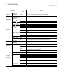
REVISIONS
The manual number is given on the bottom left of the back cover.
Print Date
Apr., 2000
Sep., 2000
Manual Number
SH(NA)-080089-A
SH(NA)-080089-B
Dec., 2003
SH(NA)-080089-C
Oct., 2004
SH(NA)-080089-D
Revision
First printing
Addition
Section 1.3, Section 2.3, 2.3.1, 2.3.2, 2.4
Correction
Section 2.1, 6.2
Correction
SAFETY PRECAUTIONS, About Manuals, Conformation to the EMC
Directive and Low Voltage Instruction, About the Generic Terms and
Abbreviations, Chapter 1, Section 2.1, 2.3, 2.4, 2.5, Section 3.1, 3.2.1,
3.3.2(2), 3.8.1, Section5.1, 5.5.1
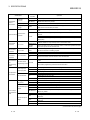
Term change
Before change
Feb., 2006
SH(NA)-080089-E
After change
GPPW
GX Developer
MELSECNET/10H
MELSECNET/H
Correction
SAFETY PRECAUTIONS, About Manuals, Conformation to the EMC
Directive and Low Voltage Instruction, How to read this manual, and
Configuration, Section 1.1 to 1.3, Section 2.1, 2.5, Section 3.1, 3.2.1,
3.3.1, 3.3.3, 3.4, 3.5, 3.5.1 to 3.5.7, 3.6 to 3.8, 3.8.1, 3.8.2, 3.9, 3.10,
3.10.1 to 3.10.3, 3.11, 3.11.1 to 3.11.4, 3.12.1, 3.13.1, 3.13.2,
Section 4.1, 4.2, 4.2.1, 4.2.2, 4.3, 4.3.2, 4.4.1, 4.4.5, 4.5, 4.5.3, 4.5.4,
4.8.2, Section 5.2 to 5.5, 5.5.2, 5.6.1, 5.6.2, Section 6.1, 6.2,
Appendix-1, Appendix-2, Appendix-2.1, Appendix-3
Deletion
Appendix-2.2 (incorporated into Appendix-2.1)
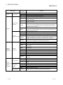
Oct., 2006
SH(NA)-080089-F
Correction
SAFETY PRECAUTIONS, Section 2.1
Aug., 2008
SH(NA)-080089-G
Change of a term
"PLC" was changed to "programmable controller".
Correction
SAFETY PRECAUTIONS, Compliance with the EMC and Low Voltage
Directives, About The Generic Terms and Abbreviations, Section 1.2,
2.1, 2.3, 2.4, 2.6, 3.1 to 3.3, 5.1, 5.3 to 5.5, 5.6.2, 5.7, 6.2, Appendix-3
Aug., 2012
SH(NA)-080089-H
Addition
Appendix 4
Correction
SAFETY PRECAUTIONS, Section 3.2.1, 3.3.3
Japanese Manual Version SH-080092-I
This manual confers no industrial property rights or any rights of any other kind, nor does it confer any patent
licenses. Mitsubishi Electric Corporation cannot be held responsible for any problems involving industrial property
rights which may occur as a result of using the contents noted in this manual.
© 2000 MITSUBISHI ELECTRIC CORPORATION
A-6
A-6
INTRODUCTION
Thank you for purchasing the MELSEC-Q series programmable controller.
Before using the equipment, please read this manual carefully to develop full familiarity with the functions
and performance of the Q series programmable controller you have purchased, so as to ensure correct use.
CONTENTS
SAFETY PRECAUTIONS..............................................................................................................................A- 1
CONDITIONS OF USE FOR THE PRODUCT .............................................................................................A- 5
REVISIONS ....................................................................................................................................................A- 6
CONTENTS....................................................................................................................................................A- 7
ABOUT MANUALS ........................................................................................................................................A-10
COMPLIANCE WITH THE EMC AND LOW VOLTAGE DIRECTIVES.......................................................A-10
HOW TO READ THIS MANUAL, AND CONFIGURATION .........................................................................A-11
ABOUT THE GENERIC TERMS AND ABBREVIATIONS...........................................................................A-12
MEANINGS OF TERMS AND THEIR CONTENTS .....................................................................................A-14
PRODUCT CONFIGURATION......................................................................................................................A-14
1 OVERVIEW
1- 1 to 1- 9
1.1 Operation Overview for QD51 (-R24)..................................................................................................... 1- 2
1.2 Features of QD51 (-R24) ........................................................................................................................ 1- 4
1.3 About the Function Added/Changed to the Function Version B ........................................................... 1- 9
2 SYSTEM CONFIGURATION AND USABLE FUNCTIONS
2.1
2.2
2.3
2.4
2.5
2.6
2- 1 to 2-12
Application Systems................................................................................................................................ 2- 1
Combining Programmable Controller CPU(s) with Other Device(s) ..................................................... 2- 5
For Use in Multiple CPU System ............................................................................................................ 2- 7
For Use with Redundant CPUs .............................................................................................................. 2- 8
For Use at MELSECNET/H Remote I/O Station.................................................................................... 2- 9
Checking the Serial Number and Function Version............................................................................... 2-11
3 SPECIFICATIONS
3- 1 to 3-66
3.1 Performance Specifications .................................................................................................................... 3- 1
3.2 RS-232 Interface Specifications ............................................................................................................. 3- 3
3.2.1 RS-232 connector specifications ..................................................................................................... 3- 3
3.2.2 RS-232 cable specifications............................................................................................................. 3- 4
3.3 RS-422/485 Interface Specifications ...................................................................................................... 3- 5
3.3.1 RS-422/485 terminal block specifications ....................................................................................... 3- 5
3.3.2 RS-422/485 cable specifications ..................................................................................................... 3- 6
3.3.3 Cautions during data communications with a RS-422/485 line...................................................... 3- 7
3.4 List of Commands and Functions in AD51H-BASIC.............................................................................. 3-10
3.5 QD51 (-R24) Internal Memory ................................................................................................................ 3-16
3.5.1 Program area.................................................................................................................................... 3-18
3.5.2 Buffer memory.................................................................................................................................. 3-20
3.5.3 Common memory............................................................................................................................. 3-23
A-7
A-7
3.5.4 Expansion register (ED0 to ED1023) .............................................................................................. 3-26
3.5.5 Special register (ED9000 to ED9127) ............................................................................................. 3-31
3.5.6 Expansion relay (EM0 to EM1023).................................................................................................. 3-35
3.5.7 Special relay (EM9000 to EM9127)................................................................................................. 3-38
3.6 Receive Buffer......................................................................................................................................... 3-41
3.7 List of GX Developer Setting Items for the QD51 (-R24)....................................................................... 3-42
3.8 List of Input/Output Signals From/To the Programmable controller CPU............................................. 3-43
3.8.1 Input (X) detailed explanation .......................................................................................................... 3-45
3.8.2 Output (Y) detailed explanation ....................................................................................................... 3-49
3.9 Relationship between the QD51 (-R24) Start Condition and the Flash ROM Execution
Program Area.......................................................................................................................................... 3-53
3.10 QD51 (-R24) Operation when the Power is Turned On ...................................................................... 3-54
3.10.1 In the case of the programming mode........................................................................................... 3-54
3.10.2 In the case of the multitask debug mode ...................................................................................... 3-55
3.10.3 In the case of the run mode ........................................................................................................... 3-56
3.11 Running a Task (a created program) ................................................................................................... 3-57
3.11.1 Conditions for permitting running of a task and start conditions................................................... 3-57
3.11.2 Starting by turning the power on or by reset (start condition: START) ........................................ 3-58
3.11.3 Starting by an interrupt from the programmable controller CPU (Start Condition: IT)................. 3-60
3.11.4 Starting by a start request from another task (Start condition: BOOT, ON)................................. 3-61
3.12 Running a BASIC Program by Multitask Processing........................................................................... 3-63
3.12.1 Multitask processing....................................................................................................................... 3-63
3.13 BASIC Program Priority Order (Priority)............................................................................................... 3-64
3.13.1 Synchronizing execution between BASIC programs (Event control) ........................................... 3-65
3.13.2 Sharing equipment (Resources) by multitasking .......................................................................... 3-66
4 ABOUT QD51 (-R24) FUNCTIONS
4- 1 to 4-24
4.1 List of Functions ...................................................................................................................................... 4- 1
4.2 Communications with a Console / Terminal........................................................................................... 4- 2
4.2.1 Communications with a console ...................................................................................................... 4- 3
4.2.2 Communications with a terminal...................................................................................................... 4- 6
4.3 Printing by a Printer................................................................................................................................. 4-10
4.3.1 Printing from a printer connected to an interface that is not set in the console ............................. 4-11
4.3.2 Printing from a printer connected to the console ............................................................................ 4-13
4.4 Communications with the External Device............................................................................................. 4-14
4.4.1 If data are being sent ....................................................................................................................... 4-14
4.4.2 If data are received........................................................................................................................... 4-15
4.5 Communications with the Programmable controller CPU ..................................................................... 4-16
4.5.1 ON/OFF data communications by general output (X/Y) ................................................................. 4-17
4.5.2 Reading and writing data from/to buffer memory............................................................................ 4-18
4.5.3 Reading and writing data from/to the programmable controller CPU ............................................ 4-19
4.5.4 Reading and writing data from/to the programmable controller CPU's expansion file register ..... 4-20
4.6 Reading and Writing Data from/to the Buffer Memory of Another Intelligent Function Module/
Special Function Module ........................................................................................................................ 4-21
4.7 Reading and Writing Clock Data ............................................................................................................ 4-22
4.8 Data Communications Between Tasks .................................................................................................. 4-23
4.8.1 ON/OFF data communications by expansion relay (EM) ............................................................... 4-23
A-8
A-8
4.8.2 Data communications by expansion register (ED).......................................................................... 4-24
4.8.3 Data communications by common memory.................................................................................... 4-24
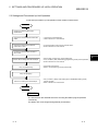
5 SETTINGS AND PROCEDURES UP UNTIL OPERATION
5- 1 to 5-17
5.1 Handling Precautions.............................................................................................................................. 5- 1
5.2 Settings and Procedures Up Until Operation ......................................................................................... 5- 2
5.3 Names of Parts and Functions ............................................................................................................... 5- 3
5.4 Connection with a Console, Debugger................................................................................................... 5- 4
5.5 Connection with the External Device...................................................................................................... 5- 5
5.5.1 Connecting to the RS-232 interface ................................................................................................ 5- 6
5.5.2 Connecting to the RS-422/485 interface ......................................................................................... 5- 8
5.6 Setting from the GX Developer............................................................................................................... 5-11
5.6.1 I/O assignment settings.................................................................................................................... 5-11
5.6.2 Switch setting for I/O and intelligent function module ..................................................................... 5-12
5.6.3 Intelligent function module interrupt point settings.......................................................................... 5-16
5.7 Maintenance, Checks ............................................................................................................................. 5-17
6 EXCLUSIVE COMMANDS
6- 1 to 6- 2
6.1 Exclusive Command List and Available Devices ................................................................................... 6- 1
6.2 Z(P). YCHECK ........................................................................................................................................ 6- 2
7 TROUBLESHOOTING
7- 1 to 7- 3
7.1 About QD51 (-R24) Status Checks ........................................................................................................ 7- 1
7.1.1 Checking the LED lighting status, communications error status and QD51 (-R24) switch
setting status .................................................................................................................................... 7- 1
7.1.2 Errors that occur in BASIC............................................................................................................... 7- 3
APPENDICES
App- 1 to App- 7
Appendix 1 Comparison of Functions with Previous Modules ................................................................AppAppendix 2 About Use of Programs from Previous Modules ..................................................................AppAppendix 2.1 About use of A1SD51S, AD51H-S3 programs ..............................................................AppAppendix 3 External Dimensions..............................................................................................................AppAppendix 4 RS-232 interfaces used for the QD51 (-R24) .......................................................................AppINDEX
A-9
1
2
2
6
7
Index- 1 to Index- 2
A-9
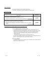
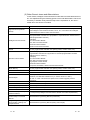
ABOUT MANUALS
The following manuals are also related to this product.
In necessary, order them by quoting the details in the tables below.
Related Manuals
Manual Name
AD51H-BASIC Programming Manual (Command)
(Corresponds to the QD51, QD51-R24, A1SD51S, AD51H-S3.)
Explains the commands, how to use the functions and the specifications of AD51H-BASIC.
(Sold separately)
AD51H-BASIC Programming Manual (Debug and Compile)
(Corresponds to the QD51, QD51-R24, A1SD51S, AD51H-S3.)
Explains concerning debugging of AD51H-BASIC, multitasking settings, and compilation
methods.
(Sold separately)
Manual No.
(Model Name Code)
SH-080090
(13JF63)
SH-080091
(13JF64)
COMPLIANCE WITH THE EMC AND LOW VOLTAGE DIRECTIVES
(1) For programmable controller system
To ensure that Mitsubishi programmable controllers maintain EMC and Low
Voltage Directives when incorporated into other machinery or equipment, certain
measures may be necessary. Please refer to one of the following manuals.
• QCPU User's Manual (Hardware Design, Maintenance and Inspection)
• Safety Guidelines
(This manual is included with the CPU module or base unit.)
The CE mark, indicating compliance with the EMC and Low Voltage Directives, is
printed on the rating plate of the programmable controller.
(2) For the product
No additional measures are necessary for the compliance of this product with the
EMC and Low Voltage Directives.
A - 10
A - 10
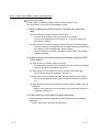
HOW TO READ THIS MANUAL, AND CONFIGURATION
How to use this manual
We will explain concerning the QD51 (-R24) for each purpose of use.
Use this manual for reference for the following contents.
(1) When desiring to know the features, functions and component
parts
(a) When desiring to know the features and functions
• The features of the QD51 (-R24) are described in Chapter 1.
• The common specifications and functions, etc. of the QD51 (-R24) are
described in Chapter 3.
(b) When desiring to know the package contents and system component parts
• The items included in the package when the QD51 (-R24) is purchased are
described in "Product Configuration" before Chapter 1.
• The user should procure parts and materials not included in the package
contents separately.
(2) When desiring to know the processing necessary to get the QD51
(-R24) started
(a) When desiring to know the startup procedure
• An abbreviated sequence of the procedures up to the point when the QD51
(-R24) is operated is described in Section 5.2.
(b) When desiring to know about connections with the console debugger
• The connection method is described in Section 5.4.
(c) When desiring to know about connection with the opposite party's device
• The connection method for each type of interface is described in Section
5.5.
(d) When desiring to know the processing necessary before the QD51 (-R24) is
started up
• Setting of the parameters used in the QD51 (-R24) using GX Developer is
explained in Section 5.6.
(3) When desiring to know about program application
When desiring to know about application of the program from the A1SD51S or
AD51H-S3
• Program application is described in Appendix 2.1.
A - 11
A - 11
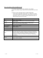
ABOUT THE GENERIC TERMS AND ABBREVIATIONS
In this manual, unless specially clarified, explanation of the Intelligent
Communications Module using the general names and abbreviated names shown
below.
(1) Generic terms and Abbreviations of Affected Modules
In this manual, programmable controller CPUs, etc. related to the Intelligent
Communications Module are displayed with the following generic terms and
abbreviations. When it is necessary to clarify the relevant model name, the
affected module's model name is included.
Generic Term/Abbreviation
Content of Generic terms and Abbreviations
ACPU
AnNCPU, AnACPU, AnUCPU
AnACPU
A2ACPU, A2ACPU-S1, A2ACPUP21/R21, A2ACPUP21/R21-S1, A3ACPU,
A3ACPUP21/R21
AnNCPU
A1NCPU, A1NCPUP21/R21, A2NCPU, A2NCPU-S1, A2NCPUP21/R21,
A2NCPUP21/R21-S1, A3NCPU, A3NCPUP21/R21
AnUCPU
A2UCPU, A2UCPU-S1, A2USCPU-S1, A2USHCPU-S1, A3UCPU, A4UCPU
AnA/AnU/QnACPU
AnACPU, AnUCPU, QnACPU
AnU/QnACPU
AnUCPU, QnACPU
QD51
Shows only the QD51.
QD51-R24
Shows only the QD51-R24.
QD51(-R24)
Shows both the AD51 and QD51-R24.
QCPU
Q00JCPU, Q00CPU, Q01CPU, Q02CPU, Q02HCPU, Q06HCPU, Q12HCPU, Q25HCPU,
Q02PHCPU, Q06PHCPU, Q12PHCPU, Q25PHCPU, Q12PRHCPU, Q25PRHCPU,
Q02UCPU, Q03UDCPU, Q04UDHCPU, Q06UDHCPU, Q10UDHCPU, Q13UDHCPU,
Q20UDHCPU, Q26UDHCPU, Q03UDECPU, Q04UDEHCPU, Q06UDEHCPU,
Q10UDEHCPU, Q13UDEHCPU, Q20UDEHCPU, Q26UDEHCPU, Q50UDEHCPU,
Q100UDEHCPU
QCPU-A
Q02CPU-A, Q02HCPU-A, Q06HCPU-A
QnACPU
Q2ACPU, Q2ACPU-S1, Q2ASCPU, Q2ASCPU-S1, Q2ASHCPU, Q2ASHCPU-S1,
Q3ACPU, Q4ACPU, Q4ARCPU
Q/QnACPU
QCPU, QnACPU
A - 12
A - 12
(2) Other Generic terms and Abbreviations
In this manual, intelligent communications module data communications devices,
etc. are explained using the following generic terms and abbreviations. When it is
necessary to indicate clearly what the object of the explanation is, the name /
model name of that item is included.
Generic Term/Abbreviation
Opposite device (external
device)
Intelligent Function Module
Intelligent Function Module
Device
Special Function Module
Buffer Memory
I/F
CH
Content of Generic terms and Abbreviations
Computer, display, measuring instrument, ID module, bar code reader, adjuster or
other intelligent communications module, UC 24, etc. connected to this intelligent
communications module for data communications.
Q series programmable controller module which runs according to commands from
the programmable controller CPU. (Equivalent to a special function module of the A
series programmable controller)
(Examples)
• CC-Link Interface Module
• A/D, D/A Conversion Module
• Ethernet Interface Module
• Serial Communications Module
Buffer memory of the intelligent function module for storing data sent to and received
from the programmable controller CPU (setting values, monitor values, etc.).
A/QnA series programmable controller modules operated by commands from the
programmable controller CPU. (Equivalent to Q series programmable controller
intelligent function modules.)
(Examples)
• CC-Link Interface Module
• A/D, D/A Conversion Module
• High Speed Counter Module
• Ethernet Interface Module
• Computer Link Module, Serial Communications Module
Buffer memory of the intelligent function module for storing data sent to and received
from the programmable controller CPU (setting values, monitor values, etc.).
Interface
MELSECNET/10
Channel
Generic product name for SWnD5C-GPPW-E, SWnD5C-GPPW-EA, SWnD5CGPPW-EV, and SWnD5C-GPPW-EVA. ("n" means version 4 or later.)
"-A" and "-V" mean "volume license product" and "version-upgrade product"
respectively.
MELSECNET/10 network system.
MELSECNET/H
RS-232 (Interface)
MELSECNET/H network system.
RS-232 compatible interface.
RS-422/485 (Interface)
YCHECK
User's Manual (Hardware) or
Hardware Manual
Programming Manual
(Commands) or Command
Manual
RS-422 and RS-485 compatible interface.
Abbreviation for Z.YCHECK or ZP.YCHECK.
GX Developer
Programming Manual (Debug
and Compile) or Debug and
Compile Manual
A - 13
Q Corresponding Intelligent Communications Module User's Manual (Hardware)
AD51H-BASIC Programming Manual (Commands)
AD51H-BASIC Programming Manual (Debug and Compile)
A - 13
MEANINGS OF TERMS AND THEIR CONTENTS
The meanings of terms used in this manual and their contents are shown below.
Term
Contents
This is a device which connects to the QD51 (-R24) and is used to perform
programming and multitasking settings.
Console
A PC/AT personal computer with the software package installed becomes a console.
Depending on the settings, the console becomes the debugger.
This device connects to the QD51 (-R24) and performs debugging. A PC/AT personal
Debugger
computer with the software package installed becomes the debugger. The debugger
can check variable values and can edit the program while it is being run.
This connects to the QD51 (–R24) and is used to display the screen and input
Terminal
characters from the keyboard.
Interpreter
This is BASIC in a format which processes while executing commands one by one.
This compiles programs created with the interpreter. It registers the compiled files and
Compiler
executes them. Compared to the interpreter, its execution speed is on the average 2
or 3 times faster.
Multitasking
This executes multiple programs by time slicing, executing them so that it seems that
they are being executed simultaneously.
This is the mode used when the console is disconnected and the QD51 (-R24) is
Run Mode
being operated independently. It is actually used when this device is being run as a
system.
Programming Mode
Multitask Debug Mode
This mode is used to connect to the console and carry out programming.
This mode changes the contents of variables and traces them while executing a
program, and carries out tracing.
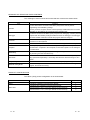
PRODUCT CONFIGURATION
The QD51 (-R24) product configuration is as shown below.
Model Name
QD51
QD51-R24
A - 14
Product Name
Quantity
Model QD51 Intelligent Communications Module
1
Model QD51-R24 Intelligent Communications Module
1
Terminal Resistor 330 Ω, 1/4 W (For RS-422 communications)
2
Terminal Resistor 110 Ω, 1/2 W (For RS-485 communications)
2
A - 14
1 OVERVIEW
MELSEC-Q
1 OVERVIEW
This manual explains the system configuration, performance specifications and
functions of the QD51 / QD51-R24 Intelligent Communications Module.
When applying the following program examples to the actual system, make sure to
examine the applicability and confirm that it will not cause system control problems.
The QD51 (-R24) has the following functions.
(1) BASIC Program-Based Functions
• Sub-CPU Function
Complex numerical calculations and functional calculations can be made with
a BASIC program.
• Monitor Display Function
It can display production conditions, the operating status, details of a
breakdown, etc.
• Key Input Function
The production schedule, production volume, operation, setting data, etc. can
be input.
• Printer Function
Production plans, performances, daily reports, breakdown details, planning
data, inspection results and test performance, etc. can be printed out.
• Data Input Function
Data can be input from a bar code reader or magnetic card reader, etc.
• External Device Connection Function
A computer, etc. can be connected to the RS-232, RS-422/485 interfaces and
data can be sent and received through a BASIC program.
• Clock Function
Clock data of the programmable controller CPU can be read and written.
(2) Offline Programming Function
BASIC programs can be created, corrected, stored to; user FD and printed out
independently by peripheral devices.
(3) Online Programming Function
BASIC programs can be created, run, and corrected from the console.
(4) Multitasking Debugging Function
BASIC programs can be debugged while they are being run.
1-1
1-1
1
1 OVERVIEW
MELSEC-Q
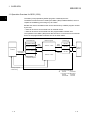
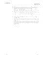
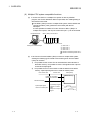
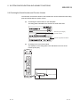
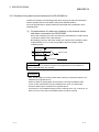
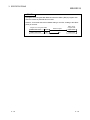
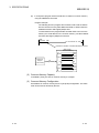
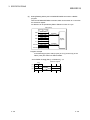
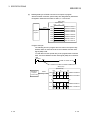
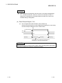
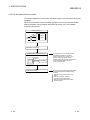
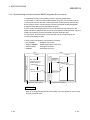
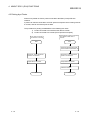
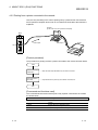
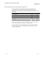
1.1 Operation Overview for QD51 (-R24)
1
The QD51 (-R24) operates by BASIC programs created by the user.
The BASIC version that can be used by the QD51 (-R24) is AD51H-BASIC, which is
capable of multitasking processing of up to 2 tasks.
Besides the various calculations that can be carried out by a BASIC program created
by the user,
• Data can be sent to and received from an external device.
• Data can be sent to and received from the programmable controller CPU.
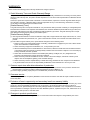
The operation in the QD51 (-R24) when data are sent to or received from an external
device or the programmable controller CPU is as shown below.
Internal Memory
Expansion Relay
Expansion Register
Programmable
controller
BASIC Program
Data
reading
Task No. 1 Area
Common Memory
Data Sending
/Reception
Data
Writing
Data
reading
Data writing
Buffer Memory
Interface
1
RS-232
RS-232
RS-422
RS-485
Sending
External
Device
Reception
Task No. 2 Area
• Data reading
• Task start request
• Interrupt request
• Data writing
1 In the case of the QD51
RS-232
2 Channels
In the case of the QD51-R24
RS-232
1 Channel
RS-422/485 1 Channel
1-2
1-2
1 OVERVIEW
MELSEC-Q
(1) Sending Data to and Receiving Data from an External Device
The QD51 (-R24) is equipped with the following interfaces.
• QD51
: 2 RS-232 channels
• QD51-R24 : 1 RS-232 channel, 1 RS-422/485 channel
Production instructions, production results and other data can be sent to or
received from a personal computer or other external device connected to the RS232 or RS-422/485 interface or the console non-procedurally.
Data such as production results can also be printed out on a printer connected to
the RS-232 interface.
(2) Sending Data to and Receiving Data from the Programmable
Controller CPU
Through the execution of programmable controller access commands
(PCRD/PCWT), the programmable controller CPU device data can be read and
written.
With the programmable controller access commands, data can also be written to
and read from the buffer memory of a special function module or an intelligent
function module.
1-3
1-3
1 OVERVIEW
MELSEC-Q
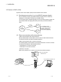
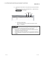
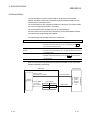
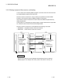
1.2 Features of QD51 (-R24)
Systems which use the QD51 (-R24) have the features shown below.
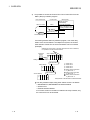
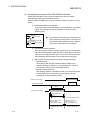
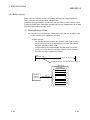
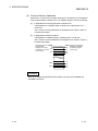
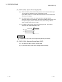
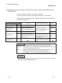
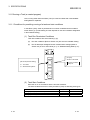
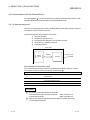
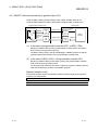
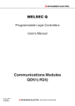
(1) Simultaneous execution of up to two BASIC programs (tasks)
Since multitask processing is possible, BASIC programs can be created by
dividing the control tasks to be done by the QD51 (-R24).
The necessary task is started depending on the control level and the system can
be controlled while exchanging data and synchronizing executions between
tasks.
d by
Divide pe
l ty
o
tr
n
co
Task 1
Controls
executed
in the QD51
It is possible to create
3 or more BASIC programs.
However, a maximum of
2 tasks (BASIC programs)
can be run simultaneously.
Task 2
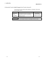
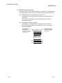
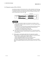
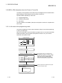
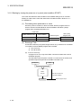
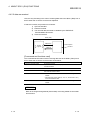
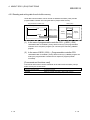
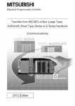
(2) Data communications with external devices
<Data communications with external devices>
Non-procedural data communications can be carried out with external devices
connected to the RS-232 and RS-422/485 interfaces.
<Data communications with a console or terminal>
The following data communications can be performed with a console or terminal
connected to the RS232 or RS-422/485 interface.
• Data display to a console or terminal
• Data input to a console or terminal
<Printout on a Printer>
Data can be printed out on a printer connected to the RS-232 interface.
Robot, bar code reader,
thermostat, etc.
QD51-R24
RUN
PROG
SD
RD
CH.1
ERR.
P.RUN
SD
CH.2
RD
PC/AT personal computer, etc.
CH. 1
External device
(printer)
CH. 2
1-4
1-4
1 OVERVIEW
MELSEC-Q
(3) Data communications with the programmable controller are
possible
Data can be sent to or received from a programmable controller CPU installed
with the QD51(-R24) or the one on the MELSECNET/H or MELSECNET/10
network.
The types of data which can be sent to and received from a programmable
controller CPU are shown below.
1)
Device writing and reading in the programmable controller CPU (Max. 960
words/1 time)
2)
Writing to and reading from the buffer memory in the intelligent function
module (Max. 960 words/ 1 time).
3)
Remote RUN/STOP of the programmable controller CPU.
4)
Interrupts to the programmable controller CPU.
(4) File control is possible
Using the console's FD or HD (hard disk), sequential files and random files can
be handled.
However, it is necessary that the console be connected at all times.
<Sequential Files>
These are files in which data can be read and written sequentially and which
enable efficient use of memory.
They are used mainly for operating instruction data files and results files, etc.
<Random Files>
These are files where reading starts from the necessary portion only and only the
necessary portion is written.
This type of file is appropriate for large volume inventory files, instruction data for
operator interfaces, master files, etc.
When reading or writing is done one time, the maximum data size is 256 bytes.
(5) Offline programming with a text editor is possible
A BASIC program can be created offline using a text editor, and the BASIC
program can then be registered.
In offline programming, the edited program cannot be run.
1-5
1-5
1 OVERVIEW
MELSEC-Q
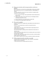
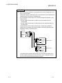
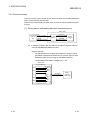
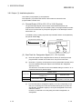
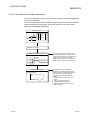
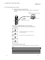
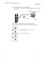
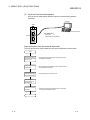
(6) Online programming is possible
By connecting the QD51 (-R24) to a PC/AT personal computer and carrying out
settings at a console, a BASIC program can be edited and debugged.
In the case of programming with a PC/AT personal computer.
RS-232 Cable
QD51-R24
QJ71E71
Q25HCPU
MELSEC
POWER
MODE
RUN
ERR.
RUN
I NI T.
OPEN
SD
QD51- R24
ERR.
COM. ERR
CH1.
CH2.
RD
CH1.
10BASE- T
USER
BAT.
BOOT
RS- 232
10BASE
User's FD
CH. 3
SDA
1
SG
PULL
USB
SDB
2
( FG)
3
RDA
4
( FG)
RS- 232
MI TSUBI SHI
+12V
RDB
12G
RS- 422
/ 485
5
6
7
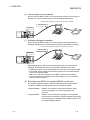
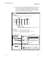
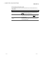
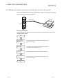
(7) Multitask debugging is possible
By connecting the QD51 (-R24) to a PC/AT personal computer and setting a
debugger, debugging can be performed while performing multitask processing.
In the case of programming with a PC/AT personal computer.
RS-232 Cable
QD51-R24
QJ71E71
Q25HCPU
MELSEC
POWER
MODE
RUN
ERR.
RUN
I NI T.
OPEN
SD
QD51- R24
ERR.
COM. ERR
CH1.
CH2.
RD
CH1.
10BASE- T
USER
BAT.
BOOT
RS- 232
10BASE
CH. 3
SDA
PULL
SDB
2
( FG)
User's FD
3
RDA
MI TSUBI SHI
1
SG
USB
RS- 232
4
( FG)
5
+12V
RDB
12G
RS- 422
/ 485
6
7
Multitask debugging is performed by inputting the Debug command from the
debugger. By executing the Debug command, the following can be done.
• The BASIC program for the specified task No. area can be run and terminated.
• The variable values specified in the BASIC program for the specified task No.
area can be read and written.
• Data can be read from and written to the QD51 (-R24)'s internal memory.
• Common events and message port use status displays, etc. can be shared
between BASIC programs.
(8) Both interpreter BASIC and compiled BASIC can be used
By compiling a BASIC program created in interpreter BASIC with the BASIC
compiler, the BASIC processing speed can be markedly increased.
Interpreter BASIC : BASIC in an execution format where the QD51 (-R24)
converts the program to machine language during
execution.
Compiled BASIC : BASIC in the format where the program is compiled (the
commands are converted to machine language) at the stage
when the program is completed and the QD51 (-R24) runs it
in machine language directly.
1-6
1-6
1 OVERVIEW
MELSEC-Q
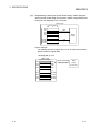
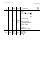
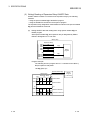
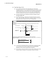
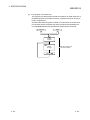
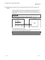
(9) Multiple CPU system compatible functions
(a)
If access to a QCPU in a multiple CPU system is done by a BASIC
program, the access destination QCPU is specified, then reading/writing of
device data is executed.
If the QD51 (-R24) is used in a multiple CPU system, set the QCPU that
controls the QD51 (-R24) (called the control CPU) with the GX
Developer.
It is also possible to install the Function Version A QD51 (-R24) in a
multiple CPU system, and only the control CPU (No. 1) can be accessed.
Peripheral Device
QD51 (-R24)'s Control CPU
1)
Setting from GX Developer.
(b)
2) 3) 4)
1
2
1
QD
51
QD51 (-R24)'s Non-control CPUs
1) : QCPU No. 1
2) : QCPU No. 2
3) : QCPU No. 3
4) : QCPU No. 4
1 : Module controlled by QCPU No. 1.
2 : Module controlled by QCPU No. 2.
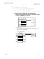
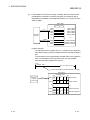
If the Function Version B QD51 (-R24) is used in a multiple CPU system,
sending the following types of data to and receiving them from the QD51
(-R24) can be done.
1) It is possible for the control CPU to read data from and write them to
the buffer memory. It is possible to use the I/O signals as the output to
contact and output signal.
2) It is possible for a non control CPU to read the data from the buffer
memory. Input/output signals can be used as contact points.
Non-control CPU
Control CPU
QD51(-R24)
Buffer Memory
FROM/TO Command
Dedicated Command
FROM Command
Input/Output Signal
used as a contact point.
1-7
Input/Output Signal
used as a contact
point.
Output to an output
signal.
X
Y
1-7
1 OVERVIEW
MELSEC-Q
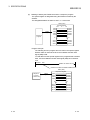
3)
It is possible to access the Control CPU / Non Control CPU from the
QD51 (-R24) by a BASIC program.
Control CPU
Non-Control CPU
QD51(-R24)
BASIC Program
(Read/Write)
03E0H to 03E3H
03FFH
The access destination
QCPU is specified by the
requesting module's I/O No.
Data
Data
Device Memory, etc.
Device Memory, etc.
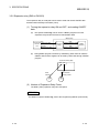
If accessing another station by a BASIC program, even if the relay
station or the access station is a multiple CPU system, the Control
CPU and Non Control CPU of the access station can be accessed.
(Example)
Whether the control CPU of the relay module is the same or different,
it is possible to access the other station.
Peripheral
Device
Source Station
1) 2) 3) 4)
1
2
1'
Setting from GX Developer.
MELSECNET/ H
Relay Station
1) 2) 3) 4)
Access Station
2
2
MELSECNET/ H
1) 2) 3) 4) 2
1) : QCPU No. 1
2) : QCPU No. 2
3) : QCPU No. 3
4) : QCPU No. 4
1 : Relay module controlled
by QCPU No. 1.
1' : QD51 (-R24) controlled
by QCPU No. 1.
2 : Relay module controlled
by QCPU No. 2.
Relay Module: MELSECNET/ H Network Module
The relay module's object during other station access is as follows.
• MELSECNET/H, MELSECNET/10 Network Module
• Q Series C24
• Ethernet Interface Module
If a Function Version A module is included in the relay modules, only
the control CPU can be accessed.
1-8
1-8
1 OVERVIEW
MELSEC-Q
1.3 About the Function Added/Changed to the Function Version B
This shows the functions that have been added to or changed in the Function
Version B QD51 (-R24).
Function
Multiple CPU
system
Compatibility
Function overview
Explanatory section
When reading device data from or writing them
to a multiple CPU system, it is possible to
access the Control CPU / Non Control CPU
specified by the user.
AD51H-BASIC
Programming Manual,
PCRD/PCWT Command
POINT
Refer to Section 2.6 concerning the method for checking the function version.
1-9
1-9
2 SYSTEM CONFIGURATION AND USABLE FUNCTIONS
MELSEC-Q
2 SYSTEM CONFIGURATION AND USABLE FUNCTIONS
This shows system configurations and the functions that can be used.
2.1 Application Systems
2
This section describes the applicable systems.
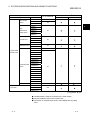
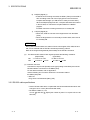
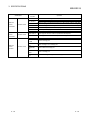
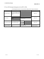
(1) Applicable modules and base units, and No. of modules
(a)
2-1
When mounted with a CPU module
The table below shows the CPU modules and base units applicable to the
QD51(-R24) and quantities for each CPU model.
Depending on the combination with other modules or the number of
mounted modules, power supply capacity may be insufficient.
Pay attention to the power supply capacity before mounting modules, and if
the power supply capacity is insufficient, change the combination of the
modules.
2-1
2 SYSTEM CONFIGURATION AND USABLE FUNCTIONS
Applicable CPU module
CPU type
Basic model
QCPU
CPU model
Q00JCPU
Q00CPU
Q01CPU
No. of modules
1
MELSEC-Q
Base unit
Main base unit
2
Extension base unit
8
24
Q02CPU
High
Q02HCPU
Performance
Q06HCPU
model QCPU
Q12HCPU
2
64
Q25HCPU
Q02PHCPU
Process CPU
Q06PHCPU
Q12PHCPU
64
Q25PHCPU
Redundant CPU
Q12PRHCPU
Q25PRHCPU
Q02UCPU
Programmable
Q03UDCPU
controller CPU
Q04UDHCPU
53
36
Q06UDHCPU
Q10UDHCPU
Q13UDHCPU
Q20UDHCPU
Universal model
QCPU
Q26UDHCPU
Q03UDECPU
Q04UDEHCPU
64
Q06UDEHCPU
Q10UDEHCPU
Q13UDEHCPU
Q20UDEHCPU
Q26UDEHCPU
Q50UDEHCPU
Q100UDEHCPU
Safety CPU
QS001CPU
N/A
3
Q06CCPU-V
C Controller
Q06CCPU-V-B
N/A
Q12DCCPU-V
: Applicable,
1 Limited within the range of I/O points for the CPU module.
2 Can be installed to any I/O slot of a base unit.
3 Connection of extension base units is not available with any safety
CPU.
2-2
2-2
: N/A
2 SYSTEM CONFIGURATION AND USABLE FUNCTIONS
MELSEC-Q
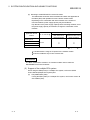
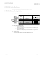
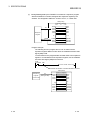
(b) Mounting to a MELSECNET/H remote I/O station
The table below shows the network modules and base units applicable to
the QD51(-R24) and quantities for each network module model.
Depending on the combination with other modules or the number of
mounted modules, power supply capacity may be insufficient.
Pay attention to the power supply capacity before mounting modules, and if
the power supply capacity is insufficient, change the combination of the
modules.
Applicable network
module
Base unit
No. of modules
1
2
Main base unit of
Extension base unit of
remote I/O station
remote I/O station
QJ72LP25-25
QJ72LP25G
Up to 64
QJ72LP25GE
QJ72BR15
: Applicable,
: N/A
1 Limited within the range of I/O points for the network module.
2 Can be installed to any I/O slot of a base unit.
REMARKS
The Basic model QCPU module or C Controller module cannot create the
MELSECNET/H remote I/O network.
(2) Support of the multiple CPU system
When using the QD51(-R24) in a multiple CPU system, refer to the QCPU
User’s Manual (Multiple CPU System) first.
(a)
2-3
Compatible QD51(-R24)
If using the QD51(-R24) on a multiple CPU system, use function version B
of the QD51(-R24) .
2-3
2 SYSTEM CONFIGURATION AND USABLE FUNCTIONS
MELSEC-Q
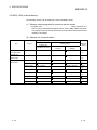
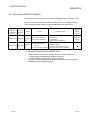
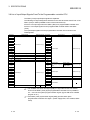
(3) Applicable Software Package
The following software package supports the QD51 (-R24)
(a)
Console/debugger software package (essential)
Product Name
Model Name
AD51H-BASIC Software Package
Remarks
SW1IVD-AD51HP-E
For PC/AT Personal Computers
CAUTION
To use SW1IVD-AD51HP-E on Microsoft Windows 95 Operating System or
Microsoft Windows 98 Operating System, operate it in the MS-DOS mode.
Do not operate on the MS-DOS prompt screen of Windows 95/Windows 98.
It will not run correctly.
R
R
R
R
R
R
(b)
R
R
Software package for programmable controllers (Essential)
Software version
GX Developer
Q00J/Q00/Q001CPU
Q02/Q02H/Q06H/Q12H/
Q25HCPU
Q02PH/Q06PHCPU
Q12PH/Q25PHCPU
Single CPU system
Version 7 or later
Multiple CPU system
Version 8 or later
Single CPU system
Version 4 or later
Multiple CPU system
Version 6 or later
Single CPU system
Multiple CPU system
Single CPU system
Multiple CPU system
Q12PRH/Q25PRHCPU
Redundant system
Q02U/Q03UD/Q04UDH/
Q06UDHCPU
Multiple CPU system
Q13UDH/Q26UDHCPU
Q03UDE/Q04UDEH/Q06UDEH/
Q13UDEH/Q26UDEHCPU
Q00UJ/Q00U/Q01U/Q10UDH/
Q20UDH/Q10UDEH/
Q20UDEHCPU
Q50UDEH/Q100UDEHCPU
Single CPU system
Single CPU system
Multiple CPU system
Single CPU system
Multiple CPU system
Version 1.15R or later
Version 8.68W or later
Version 7.10L or later
Version 1.87R or later
Version 8.45X or later
Version 8.48A or later
Version 8.62Q or later
Version 8.68W or later
Version 1.15R or later
Single CPU system
Multiple CPU system
Single CPU system
Multiple CPU system
When installing to a MELSECNET/H remote I/O station
(c)
GX Works2
Version 8.76E or later
Cannot be used
Version 1.31H or later
Version 6 or later
Version 1.40S or later
Commercially available compilation software package (necessary only for
compilation)
When using a PC/AT personal computer
Purchase the product Turdo Assembler 5.0.
For Turbo Assembler, contact Borland Software Corporation.
Product Name
Turbo Assembler
Model Name
Turbo Assembler Ver.5.0
Remarks
IBM PC/AT English Version
(4) Connection Cable for Console/Debugger
Refer to Section 5.4 for connection to a console.
2-4
2-4
2 SYSTEM CONFIGURATION AND USABLE FUNCTIONS
MELSEC-Q
2.2 Combining Programmable Controller CPU(s) with Other Device(s)
This section shows the system configurations and functions which are available when
the QD51 (-R24) is used.
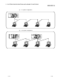
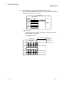
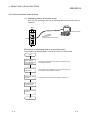
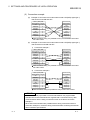
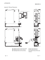
(1) System Configurations
The following shows the system configurations (combinations) for data
communications.
(a)
1:1 system configuration
QJ71E71
Q25HCPU
MELSEC
POWER
MODE
RUN
ERR.
USER
RUN
I NI T.
OPEN
SD
QD51- R24
ERR.
COM. ERR
CH1.
CH2.
RD
CH1.
10BASE- T
BAT.
BOOT
RS- 232
CH. 3
10BASE
SDA
1
SG
PULL
SDB
USB
2
( FG)
3
RDA
4
( FG)
RS- 232
MI TSUBI SHI
5
+12V
RDB
12G
RS- 422
/ 485
6
7
RS-232/422
(b)
n:1 system configuration
QJ71E71
Q25HCPU
MELSEC
POWER
MODE
RUN
ERR.
RUN
I NI T.
OPEN
SD
QD51- R24
CH1.
POWER
CH2.
QJ71E71
Q25HCPU
MELSEC
ERR.
COM. ERR
MODE
RUN
RD
ERR.
CH1.
10BASE- T
USER
BAT.
RUN
QD51- R24
ERR.
I NI T.
OPEN
SD
COM. ERR
CH1.
CH1.
BAT.
BOOT
RS- 232
10BASE
RS- 232
CH. 3
10BASE
CH. 3
SDA
PULL
SDB
PULL
2
( FG)
3
RDA
MI TSUBI SHI
SDA
1
SG
USB
RS- 232
CH2.
RD
10BASE- T
USER
BOOT
RDB
12G
RS- 422
/ 485
RS- 232
6
7
MI TSUBI SHI
1
SG
SDB
2
( FG)
3
RDA
5
+12V
USB
4
( FG)
4
( FG)
5
+12V
RDB
12G
RS- 422
/ 485
6
7
RS-485
2-5
2-5
2 SYSTEM CONFIGURATION AND USABLE FUNCTIONS
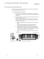
POWER
RUN
I NI T.
OPEN
SD
MODE
RUN
ERR.
1:n system configuration
(d)
m:n system configuration
QD51- R24
QJ71E71
Q25HCPU
MELSEC
(c)
MELSEC-Q
ERR.
COM. ERR
CH1.
CH2.
RD
CH1.
10BASE- T
USER
BAT.
BOOT
RS-232
CH. 3
10BASE
SDA
1
SG
PULL
SDB
USB
2
(FG)
3
RDA
4
(FG)
RS- 232
MI TSUBI SHI
5
+12V
RDB
12G
RS- 422
/ 485
6
7
RS-485
QJ71E71
Q25HCPU
MELSEC
POWER
MODE
RUN
ERR.
POWER
CH1.
CH2.
RD
CH1.
10BASE- T
QJ71E71
Q25HCPU
MELSEC
QD51- R24
ERR.
COM.ERR
RUN
I NIT.
OPEN
SD
USER
BAT.
BOOT
MODE
RUN
ERR.
USER
BAT.
BOOT
RUN
I NI T.
OPEN
SD
CH1.
CH1.
RS- 232
10BASE
CH. 3
CH. 3
SDA
SDA
PULL
2
( FG)
RDB
12 G
RS- 422
/ 485
2
3
RDA
RS- 232
6
MI TSUBI SHI
7
RS-485
2-6
SDB
( FG)
4
( FG)
4
5
+12V
1
SG
USB
3
RDA
( FG)
MI TSUBI SHI
PULL
1
SG
SDB
USB
RS- 232
CH2.
RD
RS- 232
10BASE
QD51- R24
ERR.
COM. ERR
10BASE- T
RS-485
5
+12V
RDB
12G
RS- 422
/ 485
6
7
RS-485
2-6
2 SYSTEM CONFIGURATION AND USABLE FUNCTIONS
MELSEC-Q
2.3 For Use in Multiple CPU System
This section describes the use of the QD51(-R24) in a multiple CPU system.
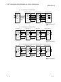
(1)
Making access from a BASIC program to a non-control CPU
When making access from a BASIC program to a non-control CPU, use the
QD51 (-R24) of function version B.
Multiple CPU system
QD51(-R24) of function version B
(2)
When other stations to be accessed belong to a multiple CPU system
When accessing a CPU that is not controlling a replay module on the access
target station, use function version B or later for the following modules:
• QD51 (-R24) on local station
• Relay modules 1 and QCPUs on local station, relay station, and accessed
station
(Example)
Whether the control CPU of the relay module is the same or different,
it is possible to access the other station.
Peripheral device
Source Station
1) 2) 3) 4)
1
2
1'
Setting from GX Developer
MELSECNET/ H
: QCPU No.1
: QCPU No.2
: QCPU No.3
1) 2) 3) 4) 2 2
: QCPU No.4
: Module used for routing, controlled
by QCPU No.1
MELSECNET/ H
1' : QD51(-R24) controlled
Access Station
by QCPU No.1
2 : Module used for routing, controlled
1) 2) 3) 4) 2
by QCPU No.2
The modules used for the routing are MELSECNET/ H network modules
Relay station
1)
2)
3)
4)
1
1 When accessing other stations, available relay modules are as follows:
• MELSECNET/H and MELSECNET/10 network modules
• Q series C24
• Ethernet interface modules
2-7
2-7
2 SYSTEM CONFIGURATION AND USABLE FUNCTIONS
MELSEC-Q
2.4 For Use with Redundant CPUs
This section describes the use of the QD51(-R24) with the Redundant CPUs.
(1) Dedicated instructions
The dedicated instructions are not applicable.
2-8
2-8
2 SYSTEM CONFIGURATION AND USABLE FUNCTIONS
MELSEC-Q
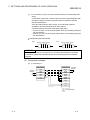
2.5 For Use at MELSECNET/H Remote I/O Station
This section describes the use of the QD51(-R24) on a MELSECNET/H remote I/O
station.
When using the QD51(-R24) with a QCPU, it is not necessary to read this section.
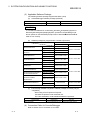
(1) System Configuration
(Example)
(Remote Master Station)
(Remote I/O Station)
QJ71
LP21
-25
QCPU
QJ72
QD51
LP25
(-R24)
-25
MELSECNET/H Remote I/O Net
QJ72
LP25
-25
(Remote I/O Station)
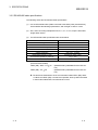
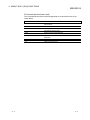
(2) Available functions
The functions which can be used when the QD51 (-R24) is installed in a
MELSECNET/H remote I/O station are shown below.
Function
Availability
Communications by BASIC program ( 1)
: Can be used.
: Cannot be used.
1 Available communications with MELSECNET/H remote I/O stations by
BASIC program are as follows:
Available Function
Function
Reading from and writing to device memory.
Reading from and writing to intelligent function
module buffer memory.
Batch read, batch write
Random read, test (random write)
Reading from and writing to the specified intelligent
function module's buffer memory.
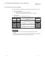
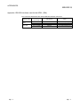
The device range of a MELSECNET/H remote I/O station which can be accessed by
reading from and writing to the device memory is as follows. (The same range as the
default QCPU settings)
For MELSECNET/H remote I/O station devices and access device ranges, refer to the
AD51H-BASIC Programming Manual.
2-9
Device Name
Device Symbol
Device Name
Device Symbol
Special Relay
SM
Link Relay
B
Special Register
SD
Data Register
D
Input Relay
X
Link Register
W
Output Relay
Y
Link Special Relay
SB
Internal Relay
M
Link Special Register
SW
2-9
2 SYSTEM CONFIGURATION AND USABLE FUNCTIONS
MELSEC-Q
REMARK
For QnA/A Series MELSECNET/10 remote I/O stations, only reading from and
writing to the intelligent function module's buffer memory can be done.
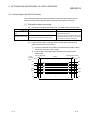
(3) Setting from GX Developer
In the case of mounting the QD51(-R24) on a MELSECNET/H remote I/O station,
set the following parameters in GX Developer.
Each setting method is the same as the parameter setting for the QD51(-R24)
installed to the QCPU station. Refer to Section 5.6 and subsequent sections.
For the method for displaying each setting screen, refer to the GX Developer
Operating Manual.
(Parameter setting sections for the QD51 (-R24) when installed to a
MELSECNET/H remote I/O station)
Parameter Setting Item
I/O Assignment
Switch setting for I/O and intelligent
function modules
Setting
Remarks
Sets the module installation information.
Refer to Section 5.6.1.
Sets the transmission specifications and
communications protocol for with other
devices, etc.
Refer to Section 5.6.2.
POINT
(1) Connect GX Developer to the MELSECNET/H remote I/O station and set the
parameters.
(2) After changing the settings, reset the MELSECNET/H remote I/O station.
2 - 10
2 - 10
2 SYSTEM CONFIGURATION AND USABLE FUNCTIONS
MELSEC-Q
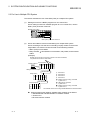
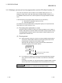
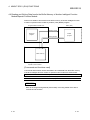
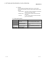
2.6 Checking the Serial Number and Function Version
The serial No. and function version of the Q series C24 can be confirmed on the rating
plate and GX Developer's system monitor.
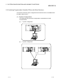
(a)
Confirming the serial number on the rated plate
The rating plate is situated on the side face of the Q series C24.
Serial No. (first 5 digits)
Function version
Relevant regulation standards
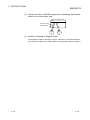
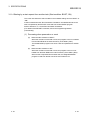
(b)
Checking on the front of the module
The serial No. on the rating plate is also indicated on the front of the
module (lower part).
QD51
020920000000000-B
Function version
Serial No.
2 - 11
2 - 11
2 SYSTEM CONFIGURATION AND USABLE FUNCTIONS
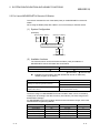
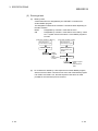
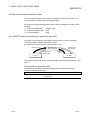
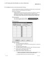
(c)
MELSEC-Q
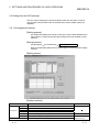
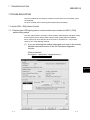
Confirming the serial number on the system monitor (Product Information
List)
To display the system monitor, select [Diagnostics] → [System Monitor] →
Product Inf. List of GX Developer.
Function version
Serial No.
1)
Product No.
Production number display
Since the QD51(-R24) does not support the production number
display, "-" is displayed.
POINT
The serial No. displayed in the Product Information List of GX Developer may be
different from the one on the rating plate and the front of the module.
• The serial No. on the raging plate and the front of the module indicates the
management information on the product.
• The serial No. in the Product Information List of GX Developer indicates the
functional information on the product, which is updated when a new function
is added.
2 - 12
2 - 12
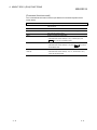
3 SPECIFICATIONS
MELSEC-Q
3 SPECIFICATIONS
The following shows the performance specifications of the QD51 (-R24).
For general specifications, refer to the QCPU User's Manual (Hardware Design,
Maintenance and Inspection).
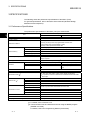
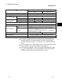
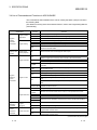
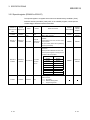
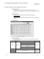
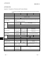
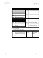
3.1 Performance Specifications
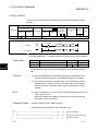
The performance specifications of the QD51 (-R24) are shown below.
Specification
Item
3
QD51
QD51-R24
Programming language
AD51H-BASIC (Interpreter, Compiler)
Number of tasks
2
Task start conditions
• Start by power is turned on.
• Start by an interrupt from the programmable controller CPU.
(Not possible when compiled BASIC is used.)
• Start by a start request from another task.
Internal memory
Program
Max. 64 kbytes (Task 1 capacity + Task 2 capacity ≤ 64 kbytes)
Common memory
8 kbytes
Buffer memory
6 kbytes
Expansion relay (EM)
1024 points
Expansion register (ED)
General Input/Output
1024 points
Input: 26 points
Output: 23 points
Yes (Flash ROM write protectable) (
Memory protection
Interfaces
CH.1
RS-232 compatible (D-sub 9p)
CH.2
RS-232 compatible (D-sub 9p)
Communications method
Full duplex communications
Synchronization method
Start stop synchronization method
Data format (
300, 600, 1200, 2400, 4800, 14,400, 19,200, 28,800, 38,400 (bps)
It is possible to use the 2 interfaces with a total transmission rate within
38,400 bps.
2
)
2
)
Start bit
1
Data bits
7 or 8
Parity bit
Even, Odd, None
Stop bit
1 or 2
DTR/DSR (ER/DR) control
RS/CS control
Transmission control
)
RS-232 compatible (D-sub 9p)
RS-422/485 (Two-piece terminal
block)
CH.3
Transmission rate (
1
CD(DCD) Signal control
RS-232 only can be used, RS-422/485 cannot be used.
None
DC1/DC3 (Xon/Xoff control)
Both RS-232 and RS422/485 can be used.
DC2/DC4 control
None
Clock function
None
Power failure maintenance
None
User program ROM Storage
The program area only can be stored in Flash ROM.
(Continued to the next page)
1 For details, refer to Section 5.6.2.
2 The transmission rate and data format are set using the BASIC program
(ZOPEN command).
For details, refer to the Programming Manual (Commands).
3-1
3-1
3 SPECIFICATIONS
MELSEC-Q
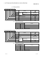
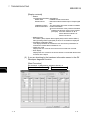
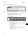
Specification
Item
QD51
QD51-R24
Console
PC/AT personal computer.
Multitask debugging
Possible (when the debugger is used)
Line configuration (
3
)
Transmission distance
(Total cable length)
RS-232
1:1
RS-232
Max. 15 m
RS-422/485
Number of writes to flash ROM
32 points per slot (I/O assignment: Intelli: 32 points) (
4
)
RS-232
7/0.127 P HRV-SV External diameter 8.5 mm or greater (Manufactured by
Oki Electric Wire (Corp.) The number of pairs is shown in the part)
RS-422/485
3P External diameter approx. 6.5 mm
SPEV (SB) –MPC-0.2
(Manufactured by Mitsubishi Electric Wire Co. Ltd.)
SPEV (SB) -0.2
3P External diameter approx. 7.5 mm (Manufactured by
Mitsubishi Electric Wire Co. Ltd.) ( 5)
Recommended cables
5 V DC internal current consumption
Weight
Max. 1200 m (Total cable length)
Maximum 100,000 times to the same area.
Number of occupied I/O points
External dimensions
1 : 1, 1 : n, n : 1, m : n
RS-422/485
0.26A
98 (3.86 in.) (H)
0.31A
27.4 (1.08 in.) (W)
90 (3.54 in.) (D) [mm]
0.20kg (0.44lb)
3 This shows combinations when the external device(s) and programmable
controller CPU(s) are connected. (External device side : Programmable
controller CPU side) The value, n or the total of m + n becomes a maximum
of 32.
4 To use the QD51(-R24), switch settings must be configured by GX Developer.
Refer to Section 5.6 for the switch settings of GX Developer.
5 The electrical characteristics of the recommended cables SPEV (SB) –MPC0.2 3P and SPEV (SB) -0.2 3P are equivalent, however, their external
dimensions and internal wire colors are different each other.
3-2
3-2
3
3 SPECIFICATIONS
MELSEC-Q
3.2 RS-232 Interface Specifications
This section describes the RS-232 interface specifications.
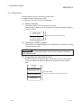
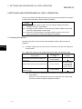
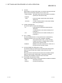
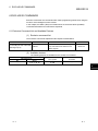
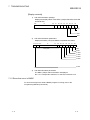
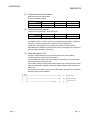
3.2.1 RS-232 connector specifications
The connector specifications for the RS-232 used to connect with another device are
shown below.
(1)
3-3
Each control signal is explained below. (The connector pin No. is shown in
parentheses.)
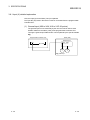
1)
CD(DCD) Signal (1)
• Nothing is being controlled in the QD51 (-R24).
• The signal status can be read by a BASIC program.
2)
RD(RXD) Signal (2)
This is the signal for data reception.
3)
SD(TXD) Signal (3)
This is the signal for data sending.
4)
ER(DTR) Signal (4)
• If DTR/DSR control is being exercised, the QD51 (-R24) turns ON or
OFF depending on the size of the empty space in the OS area for
reception data storage. (It is ON when it is ready to receive data.)
When the ER(DTR) Signal is OFF, reception data have been stored
in the OS area, so read out the reception data from a BASIC
program. If DTR/DSR control is not being exercised, it is normally
ON.
5)
DR(DSR) Signal (6)
• If DTR/DSR control is being exercised, when this signal is OFF, data
are not sent to the target device from the QD51 (-R24).
When the target device is in the ready-to-receive state, set it so that
it is normally ON.
• If DTR/DSR control is not being exercised, the DR(DSR) Signal's
status is disregarded.
3-3
3 SPECIFICATIONS
MELSEC-Q
6)
RS(RTS) Signal (7)
• If RS/CS control is being exercised, the QD51 (-R24) is turned ON or
OFF according to the size of the empty space in the OS area for
reception data storage. (It is ON when it is ready to receive data.)
When the RS(RTS) Signal is OFF, reception data have been stored
in the OS area, so read out the reception data from a BASIC
program.
If RS/CS control are not being exercised, it is normally ON.
7)
CS(CTS) Signal (8)
• When OFF, data are not sent to the target device from the QD51
(-R24).
• When the target device is in the ready-to-receive state, set it so that
it is normally ON.
REMARK
During data communications, the status of each control signal, DTR, DSR, RS and
CD, can be checked with the ZCTRL command processing code 33.
Refer to the Programming Manual (Commands) for the ZCTRL command.
(2)
The ON and OFF states of each signal represent the following conditions.
(Output Side)
(Input Side)
ON : 5 V DC to 15 V DC
3 V DC to 15 V DC
OFF : 15 V DC to 5 V DC
15 V DC to 3 V DC
(3) Interface connector
Connectors of 9-pin D-sub (female) screw type (mating screw M2.6) are used as
RS-232 interface connectors for the QD51(-R24).
For the relevant models, refer to Appendix 4.
Use the following as a connector shell for the connection cable of
the QD51(-R24) side.
• DDK Ltd.
Plug, shell: 17JE-23090-02 (D8A) (-CG)
3.2.2 RS-232 cable specifications
• Use an RS-232 cable which complies with the RS-232 standard and which has
a length of 15 m or less. (Recommended cable)
• Oki Electric Cable Co., Ltd.
7/0.127 P HRV-SV ( : Specify the number of pairs. For 13 pairs 7/0.127 13P
HRV-SV)
3-4
3-4
3 SPECIFICATIONS
MELSEC-Q
3.3 RS-422/485 Interface Specifications
This section describes the RS-422/485 interface specifications.
3.3.1 RS-422/485 terminal block specifications
The following shows the RS-422/485 terminal block specifications for connection to the
target device.
SDA
SG
SDB
(FG)
RDA
(FG)
RDB
(1)
(2)
3-5
Signal direction
Signal
abbreviation
Signal name
SDA
SDB
RDA
RDB
SG
FG
FG
Send Data (+)
Send Data (-)
Receive Data (+)
Receive Data (-)
Signal Ground
Frame Ground
Frame Ground
QD51
-R24
External
device
Each signal is explained below.
1)
SDA and SDB signals
Signals for sending data to the target device from the QD51 (-R24).
2)
RDA and RDB signals
Signals for the QD51(-R24) to receive data from the target device.
Terminal resistor
Connect terminal resistors in accordance with Section 5.5.2.
3-5
3 SPECIFICATIONS
MELSEC-Q
3.3.2 RS-422/485 cable specifications
The following shows the RS-422/485 cable specifications.
(1)
Use an RS-422/485 cable (cable connected to the QD51(-R24) terminal block),
which satisfies the following specifications, with a length of 1200 m or less.
(2)
Also, when connecting multiple devices at 1:n, n:1, or m:n, keep the total cable
length within 1200 m.
(3)
The RS-422/485 cable specifications are shown below.
Item
Description
Cable Type
Shielded Cable
Number of Pairs
3
Conductor Resistance (20°C)
88.0 Ω / km or less
Insulation Resistance
10,000 MΩ·km or greater
Voltage Resistance
500 V DC 1 minute
Electrostatic Capacity (1 KHz)
Average 60 nF/km or less
Characteristic Impedance (100 KHz)
110 +/- 10Ω
Recommended conductor size
0.2 mm to 0.75 mm
2
2
(Recommended Cables)
SPEV (SB) – MPC –0.2 3P : (Manufactured by Mitsubishi Electric Wire Co.
Ltd.)
SPEV (SB) – 0.2 3P
: (Manufactured by Mitsubishi Electric Wire Co.
Ltd.)
The electrical characteristics of the recommended cables SPEV (SB) -MPC0.2 3P and SPEV (SB) -0.2 3P are equivalent, but they differ somewhat
in their external dimensions and internal wire colors.
3-6
3-6
3 SPECIFICATIONS
MELSEC-Q
3.3.3 Cautions during data communications with a RS-422/485 line
Caution is necessary in the following points when carrying out data communications
with the opposite device via the QD51 (-R24)'s RS-422/485 interface.
As for the opposite device, please send and receive data with consideration of the
following points.
(1) Countermeasure for data error reception on the external device
side when connected to the RS-422/485
When data containing errors are received by the external device, install a pull-up
or pull-down resistor in the external device.
By installing a pull-up or pull-down resistor (the criterion for the resistance value
is approximately 4.7 kΩ, 1/4 W) it is possible to prevent reception of data
containing errors.
RDA 4.7kΩ1/4W
Terminal
RDB Resistor
4.7kΩ1/4W
+
-
Receiving Data
Opposite Device
POINT
If there is a pull-up or pull-down resistor in the opposite device, there will be no
errors in the data which are received.
REMARK
Here, we will explain concerning cases where a pull-up or pull-down resistor is not
installed in the opposite device.
When no station is sending data, the send line is in the high impedance state.
In such a case, transmission may be unstable due to noise, etc. and thereby
erroneous data may be received on the opposite device.
At such a time, it is possible that parity errors or framing errors, etc. could occur, so
when an error occurs, skip over the data that are sent at such a time.
3-7
3-7
3 SPECIFICATIONS
MELSEC-Q
(2) Sending/receiving data to/from RS-422/485 interfaces
Enable high impedance control in the processing code 48 of the ZCNTL
instruction (Specifying high impedance control).
Doing so allows the QD51-R24 to control "Output Control Input" (refer to 1) to 3)
below).
1)
SDA
RS-422/485 Interface Configuration
In the case of the RS-422-485 interface, the configuration of the QD51
(-R24) driver (Send) and receiver (Receive) are as shown in the
following figure.
Driver
Send Data
SDB
Output Control Input ( 1)
RDA
Receiver
Receive Data
RDB
1 The "Output Control Input" (also called the send
gate) of the driver (Send) portion in the figure at
left decides whether data from SDA or SDB are
output to an external device or not output.
2)
RS-422/485 Interface Operation
In the above figure, when the "Output Control Input" is in the ON state,
it enters the low impedance state (the state in which data can be sent).
Also, when the "Output Control Input" is in the OFF state, it enters the
high impedance state (the state in which data are not being sent).
3)
QD51 (-R24) send start timing and send processing end timing
• Send start timing
When data is sent, the high impedance status started by the
operation described in above 1), 2) is terminated, then a mark of
several bits is output, and the actual data is output.
• Send processing end timing
After sending of data is completed, several μs are necessary for the
Hardware gate OFF time until the send processing is ended
(changed to the high impedance state).
(Output Control Input)
Data
Opposite Device Side
QD51-R24 Side
(Output Control Input)
Data
Mark of several bits is output
Data sending time
range
Hardware Gate OFF time
"Output Control Input"
ON time range
(Low impedance state)
The QD51-R24 is in the data
sending/reception enabled
state.
3-8
"Output Control Input"
OFF time range
(High impedance state)
The QD51-R24 is in the data
reception enabled state.
3-8
3 SPECIFICATIONS
MELSEC-Q
POINT
(1)
When connecting each device's send signal line in system configuration of n:1
or m:n communication
Turning ON "Output Control Input" at 2 or more locations means that data are
output (sent) from the devices simultaneously.
For normal data communications, the following settings are required on the
external device.
• Set the "Output Control Input" so that it is in the ON state only when
sending data.
• Set the "Output Control Input" so that it is in the OFF state when data are
not being sent.
To automatically control "Output Control Input", enable high impedance
control in the processing code 48 of the ZCNTL instruction (Specifying high
impedance control) on the QD51-R24.
QD51-R24
SDA
Send Data
SDB
Output Control Input
Receive
Data
RDA
RDB
SDA
SDB
Send Data
Output Control Input Opposite Device
RDA
RDB
SDA
SDB
Receive
Data
Send Data
Output Control Input Opposite Device
RDA
RDB
Receive
Data
In the above wiring, sending and receiving are connected, the data sent by
yourself is being received by yourself. Be sure to carry out programming so
that such data are discarded by the BASIC program.
3-9
3-9
3 SPECIFICATIONS
MELSEC-Q
3.4 List of Commands and Functions in AD51H-BASIC
The commands in AD51H-BASIC which can be used by the QD51 (-R24) are shown in
the following table.
(For details concerning each command and function, refer to the Programming Manual
(Commands).)
Classification
Program
creation,
correction
commands
Memory
capacity read
function
Program creation
preparations
Program editing
Reading of the
memory capacity
Command,
Function
NEW
Deletes programs in the program area and initializes all the variables.
AUTO
Automatically displays line numbers at the beginning of each line.
CLEAR
Initializes all variables and sets up the memory area.
DELETE
Deletes the specified range of a program.
RENUM
Reassigns line numbers of a program.
LIST
Displays all or a part of programs in the program area.
ZBAS
Returns the number of the BASIC task area in which the program currently being
created or executed resides.
FRE
Returns the size of the unused program area in bytes.
RUN
Program execution CONT
Program
execution,
control
commands
Resumes the program execution that was stopped by the STOP or END instructions.
CHAIN
Deletes all or a part of the currently executing program, and reads and executes
the specified program.
FOR to NEXT
Repeatedly executes a series of commands the specified number of times.
Program control
END
In the programming mode, pauses program execution to wait for command input.
In the run mode, stops program execution and puts the module into an idle state.
In the programming mode, terminates program execution to wait for command
input.
In the run mode, terminates program execution and puts the module into an idle
state.
WHILE to WEND
Repeatedly executes a group of commands between WHILE and WEND while the
specified conditions are met.
GOTO
Changes the program flow to move to the specified line unconditionally.
GOSUB to
RETURN
Branches to a subroutine and returns to the line of the specified line number.
ON GOSUB
IF GOTO ELSE
IF THEN ELSE
Format
conversion
command
Reads a program from a memory card, or the FD or HD, and executes it.
Resumes the program execution that was stopped by CTRL + C or BREAK key.
Resumes the program execution after error handling by the ON ERROR GOTO
instruction.
STOP
Program
debugging
Starts execution of the program in the program area.
RESUME
Program branching ON GOTO
Program
debugging
command
Operation
Branches to one of the lines specified with line numbers according to the value.
Branches to one of the lines specified with the line numbers according to the value.
Selects the branch destination according to the result of the formula calculation.
TRON
Starts program tracing.
TROFF
Resets the program tracing set by TRON.
CDBI
Converts a double precision real number to a 2-word (32-bit) integer for
programmable controller CPUs.
CSNI
Converts a single precision real number to a 2-word (32-bit) integer for
programmable controller CPUs.
Format conversion
(Continued from the previous page)
3 - 10
3 - 10
3 SPECIFICATIONS
Classification
MELSEC-Q
Command,
Function
Operation
Command to
write to the
designated bit
Writing to the
designated bit
WTSET
Writes 0 or 1 to the specified bit of an integer array variable.
Command to
read from the
designated bit
Reading from the
designated bit
RDSET
Reads 1-bit data from the specified bit of an integer array variable.
Character
ASCII ASC
conversion
CHR$
Returns a character code corresponding to the head of a string expression.
Character
STR$
Number conversion VAL
Recognizes a value as a decimal number and converts it to a character string.
Number
Character string
conversion
Character
string functions
Character sampling
Returns a numerical value that is represented by a character string.
HEX$
Converts a decimal number to a hexadecimal string.
OCT$
Converts a decimal number to an octal string.
BIN$
Converts a decimal number to a binary string.
LEFT$
Extracts the specified number of characters from the left of a character string
MID$ (Second)
Extracts a partial string starting from the specified position in the original character
string.
RIGHT$
Extracts the specified number of characters from the right of a character string.
STRING$
Returns the specified number of the specified characters.
SPACE$
Returns a null string of the specified length.
Character search
INSTR
Searches for the specified character string in the entire source string and returns
the position of the first match.
Character string
length search
LEN
Returns the number of characters composing a character string.
Format control
Format control
function
Screen control
Screen control
command
SPC
Returns the specified number of spaces.
TAB
Moves the currently displayed character position to the specified position.
CONSOLE
Specifies the number of items to be displayed on the console screen.
CLS
Clears the screen display.
LOCATE
Specifies the display position on the console screen.
ZOPEN
Opens a communication channel (port) in preparation for performing
communications with an external device.
ZCLOSE
Closes the communication channel (port) used for communications with external
devices.
BEEP
Makes a buzzer sound from the speaker built in the console.
Port assignment
Buzzer output
Input/Output
Control
Commands
Returns a character whose code is an integer expression value.
Printer output
LLIST
Outputs all or a part of programs in the program area to a printer.
LPRINT
Outputs data to a printer.
LPRINT USING
Outputs data in the specified format to a printer.
LFILES
Outputs the names of the files on an FD or HD to a printer.
ZLDV
Selects a printer port.
WIDTH
Sets the output width in the printer.
PRINT
Displays data on the screen.
Output to screen
PRINT USING
Displays a character string or a numeric value in the specified format.
KEY LIST
Displays a character string defined for a function key on the screen.
Output to port
ZSEND
Sends data from the specified port.
(Continued from the previous page)
3 - 11
3 - 11
3 SPECIFICATIONS
Classification
Input/Output
Control
Commands
Input Functions
MELSEC-Q
Command,
Function
Operation
INPUT
Used to input data from the keyboard.
LINE INPUT
Stores an entire key-input line (255 characters or less) into the character string
variable area without any breaks.
Input from port
ZRECEIVE
Receives data from a communication port.
Changing of port
settings
ZCNTL
Used to set communication data to the currently open communication port, or to
read out the communication port status.
INKEY$
Returns a character input from the keyboard, or a blank string (" ") if nothing is
input.
Input from
keyboard
Inputs from the
keyboard
Reads a character string of the specified length from the console keyboard and
returns it.
INPUT$
Reads a character string of the specified length from a sequential file and returns it.
Reads a character string of the specified length from a communication port of the
QD51(-R24).
Port Control
Functions
Port control
Error Control
Functions
Error control
Error
Information
Functions
Error Information
COM
ON/OFF/STOP
Enables, disables or stops interrupts from communication lines.
ON COM
GOSUB
Defines the starting line of the processing routine, to which the operation branches
upon interrupt from a communication line.
ON ERROR
GOTO
Enables interrupt processing in the case of an error, and moves the operation to
the first line of the error handling program.
ERROR
Generates an error of the specified error code.
ERR
Returns a detected error code.
ERL
Returns the number of the line where an error was detected.
Recursive
Commands to
Recursion to the
SYSTEM
the
programming mode
Programming
Mode
Input / Output of
BASIC programs
File Operation
Commands
File maintenance
File bugger
assignment
Input / Output
Commands to
Files
Stops the control of the BASIC interpreter and returns to the QD51(-R24)'s system
mode.
Stops offline programming and returns to the main menu.
LOAD
Reads programs on an FD or HD into the program area.
MERGE
Merges a program in the program area with another on an FD or HD.
SAVE
Saves programs to an FD or HD.
FILES
Displays the names of the files stored on an FD or HD.
KILL
Deletes files from an FD or HD.
Deletes system names in an FD or HD.
NAME
Renames a program or data file on an FD or HD.
OPEN
Opens a file and enables its I/O processing.
CLOSE
Terminates I/O processing of a file.
PRINT #
Writes data to a sequential file.
PRINT # USING Writes data to a sequential file using the specified format.
Sequential file input
INPUT #
Reads data from a sequential file.
/ output
Reads out an entire line (255 characters) into the character string variable area
LINE INPUT #
without any breaks.
FIELD
Allocates the area for the specified variable to the random file buffer.
LSET
Left-aligns and moves data to the random file buffer for execution of the PUT
instruction.
Random file input /
output
RSET
Right-aligns and moves data to the random file buffer for execution of the PUT
instruction.
PUT
Writes 1-record data from the buffer to a random file.
GET
Reads 1-record data from a random file into the buffer.
(Continued from the previous page)
3 - 12
3 - 12
3 SPECIFICATIONS
Classification
File information
File information
functions
Character string
Number
File Data
MELSEC-Q
Command,
Function
EOF
Returns -1 if the end of a sequential file is detected.
LOF
Returns the file size as the number of sectors.
LOC
Returns the current logical location within a file.
CVI
Converts a character string converted by the MKI$ function back to an integer.
CVS
Converts a character string converted by the MKS$ function back to a single
precision real number.
CVD
Converts a character string converted by the MKD$ function back to a double
precision real number.
CVSMBF
Converts a character string, which was converted from an AD51H-BASIC single
precision real number by the MKS$ function, into the internal representation of a
floating point real number (IEEE single-precision representation) used in QCPU,
AnA/AnU/QnACPU, AnUSCPUs.
CVDMBF
Converts a character string, which was converted from an AD51H-BASIC double
precision real number by the MKD$ function, into the internal representation of an
IEEE double precision number.
MKI$
Converts integer-type numbers to character strings.
MKS$
Converts single-precision type numbers to character strings.
MKD$
Number
Character string MKSMBF$
MKDMBF$
Definition,
declaration
commands
Definitions,
declarations
Data operations
Number,
character string
operation
Substituting for
commands
variables
Replacement of
character strings
Operation
Converts double-precision type numbers to character strings.
Converts floating point real number data in internal representation (IEEE singleprecision representation) used in QCPU, AnA/AnU/QnACPU, AnUSCPUs into a
character string that can be changed into a numeric by the CVS function.
Converts IEEE double-precision data in internal representation into a character
string that can be changed into a numeric by the CVD function.
DEF FN
Defines a user function and names it.
DEFINT
Defines variables that start with the specified characters as integer types.
DEFSNG
Defines variables that start with the specified characters as single precision real
number types.
DEFDBL
Defines variables that start with the specified characters as double precision real
number types.
DEFSTR
Defines variables that start with the specified characters as character types.
KEY
Defines a character string to each of the console's function keys.
DIM
Specifies the size of an array variable and allocates a necessary memory area.
ERASE
Deletes the array defined by the DIM instruction from the memory.
REM
Provides comments (remarks) in the program.
COMMON
Sets variables, etc. used for transition to the program to be executed by the CHAIN
instruction.
DATA
Specifies numeric values or character strings to be read by the READ instruction.
READ
Reads values defined by the DATA instruction and assigns them to variables.
RESTORE
Specifies the first line number of the DATA instruction data that are to be read by
READ.
LET
Assigns the expression value to a variable.
SWAP
Swaps the values of two variables.
ZMOVE
Transfers data between variables.
BSWAP
Swaps two values in byte units.
MID$ (Part1)
Replaces a part of a character string with another character string.
(Continued from the previous page)
3 - 13
3 - 13
3 SPECIFICATIONS
Classification
MELSEC-Q
Command,
Function
ABS
Returns an absolute value for the expression.
ATN
Returns the arctangent (tan-1) for the expression.
COS
Returns the trigonometric cosine value.
EXP
Returns the exponential function value of base e.
FIX
Returns only the integer part after truncating the fractional part of a numeric value.
INT
Returns an integer value for the expression
LOG
Returns a natural logarithm value.
RND
Arithmetic functions ROT
Number
functions
Number search
Operation
Returns a random number.
Rotates the memory contents of the specified value and returns the bit-rotated value.
SGN
Returns the sign of a value.
SIN
Returns the trigonometric sine value.
SQR
Returns the square root value.
TAN
Returns the trigonometric tangent value.
SHA
Arithmetically shifts the memory contents of the specified value and returns the
shifted value.
SHT
Logically shifts the memory contents of the specified value and returns the shifted
value.
SEARCH
Searches for the specified value from the elements of a given array variable and
returns the location of the element.
CDBL
Converts an integer or single precision real number into a double precision real number.
CSNG
Converts an integer or double precision real number into a single precision real
number.
Format conversion CINT
functions
CIDB
Converts a single or double precision real number into an integer.
Converts a 2-word (32-bit) integer used in programmable controller CPUs into a
double precision real number.
CISN
Converts a 2-word (32-bit) integer used in programmable controller CPUs into a
single precision real number.
Programmable
Programmable
controller
controller access
access
functions
PCRD
Reads various data from a programmable controller CPU.
Port switching
commands
ZIDV
Specifies where the data is to be input by INPUT or any other instruction.
ZODV
Specifies where the data is to be output by PRINT or any other instruction.
Buffer memory
Buffer memory
access
access
functions
GETMEM
Reads data from the QD51(-R24)'s buffer memory, common memory or extension
registers (ED).
PUTMEM
Writes data to the QD51(-R24)'s buffer memory, common memory or extension
registers (ED).
Buffer memory
Buffer memory
access
access
Variable
B@
Reads or writes bit information in the extension relays (EM), special relays (EM)
and general-purpose inputs (X) and outputs (Y).
W@
Reads or writes word information in the extension registers (ED) or special registers
(ED).
TIME$
Sets up the time data (Hr, Min, Sec) of a programmable controller CPU and reads it
out.
DATE$
Sets up the date data (Yr, Mon, Day, Day of Week) of a programmable controller
CPU and reads it out.
Port switching
Clock function
Clock functions
commands
Writes various data to a programmable controller CPU.
PCWT
Operates a programmable controller CPU.
(Continued from the previous page)
3 - 14
3 - 14
3 SPECIFICATIONS
Classification
MELSEC-Q
Command,
Function
ZEVENT
DEF ZEVENT
Real time
control
commands
Real time
control
commands
Real time
control
functions
3 - 15
Real time control
Real time control
Real time control
ZRELEASE
Operation
Enables or disables event generation.
Defines an event for synchronizing execution between programs.
Defines an event to be triggered according to the QD51(-R24)'s extension relay (EM).
Allows other programs to use a resource to which a resource number is assigned.
ZRESERVE
Prohibits other programs from using a resource to which a resource number is assigned.
ZSIGNAL
Generates the specified event from the program.
ZSTART
Starts the specified program.
ZURGENCY
Changes the priority of a program.
ZWAIT DELAY
Pauses program execution until the specified time has elapsed.
ZWAIT EVENT
Pauses program execution until the specified event is generated.
ZMESSAGE
Defines a message port.
ZMESSAGE
CLOSE
Closes a message port.
ZMESSAGE
GET
Reads message from a message port.
ZMESSAGE
KILL
Deletes a defined message port.
ZMESSAGE
OPEN
Opens a message port.
ZMESSAGE
PUT
Writes the following messages to the message port.
3 - 15
3 SPECIFICATIONS
MELSEC-Q
3.5 QD51 (-R24) Internal Memory
The following memory can be used by the user in the QD51 (-R24).
(1) Memory where programs for execution can be stored
• Program Area · · · · · · · · · · · · · · · · · · · · · · · · · · · · · · · · · · ·Refer to Section 3.5.1
This is memory where BASIC programs which run the QD51 (-R24) are stored.
The program area can execute a maximum of two tasks and it has a maximum
capacity of 64 k bytes.
(2) Memory for communications
Address
Item
Content
Programmable
controller CPU
FROM/TO command
BASIC Program
GETMEM/PUTMEM
command
Special Variable
B@/W@
Reference
Section
Communications with
the programmable
controller CPU
Buffer memory
0000H to 0BFFH
0000H to 17FFH
Section
3.5.2
Communications
between tasks
Common memory
0C00H to 1BFFH
1800H to 37FFH
Section
3.5.3
Reading/writing
ON/OFF data
Expansion register
1C00H to 1FFFH
ED0000 to ED1023
Section
3.5.4
2380H to 23BFH
EM0000 to EM1023
Section
3.5.6
2400H to 247FH
ED9000 to ED9127
Section
3.5.5
2500H to 2507H
EM9000 to EM9127
Section
3.5.7
System Area
Expansion relay
System Area
Special register
System Area
Special relay
System Area
3 - 16
3 - 16
3 SPECIFICATIONS
MELSEC-Q
CAUTION
Internal memory is not backed up by a battery.
If the QD51 (-R24)'s power is turned OFF, the BASIC program written to it and
the data in the buffer memory, etc. are erased. Therefore, observe the following
(1) and (2).
(1) Save the created BASIC programs in a flash ROM before turning the power
off.
The following functions stop during a flash ROM update.
• Communications with external devices
• Communications with the programmable controller CPU
• Execution of the BASIC program
• Time measurement of the timeout processing
It is recommended to update the flash ROM before any of these operations
and do not update during the operations.
It may take one to two minutes to update the flash ROM.
(2) Transmit data of the buffer memories, etc. to a latched device in the
programmable controller or to a file register.
3 - 17
3 - 17
3 SPECIFICATIONS
MELSEC-Q
3.5.1 Program area
Following programs can be stored in the program area:
• BASIC programs created at the console
• Programs for execution read from the flash ROM
(1) Memory Capacity
The program area's maximum capacity is 64 k bytes.
This 64 k bytes is divided so it can be used for a maximum of 2 BASIC programs
(Task 1 to Task 2).
Task No. 1 Area
(Max. 64 k bytes)
Maximum 64 k bytes (total for 2 tasks)
Task No. 2 Area
(Max. 64 k bytes)
(2) Capacity for 1 BASIC program
The capacity for one BASIC program can be selected from 16 k bytes, 32 k bytes,
48 k bytes and 64 k bytes.
CAUTION
If compiled BASIC is used, approximately 2 times as much capacity is required as
with interpreter BASIC.
(3) Configuration for each Task No. Area
Besides the area for the BASIC program, an OS area, an area for the variables
used in that task and a random file buffer area are included in each Task No.
Area.
OS Area
(1 k byte)
BASIC Program Area
One Task No. Area
(16 k bytes, 32 k bytes, 48 k bytes and 64 k bytes)
Random File Buffer Area
Variable Area
3 - 18
3 - 18
3 SPECIFICATIONS
MELSEC-Q
POINT
A program for running the flash ROM is read to the QD51 (-R24)'s program area
when the module is powered ON or is reset.
However, for an area where the multitask setting is set "ON", reading to the QD51
(-R24) is not done.
Program for running flash ROM
3 - 19
BASIC Task 1 Area
START
BASIC Task 2 Area
ON
BASIC Program
QD51 (-R24)
Program Area
Task 1 Area
Task 2 Area
3 - 19
3 SPECIFICATIONS
MELSEC-Q
3.5.2 Buffer memory
Buffer memory is memory for carry out sending and receiving of data between the
QD51 (-R24) and the programmable controller CPU.
(Data from the programmable controller CPU that are written to buffer memory can be
read from multiple tasks. Data written to buffer memory from multiple tasks can be read
from the programmable controller CPU.)
(1) Reading/Writing of Data
(a)
Data from the programmable controller CPU are read from or written to the
buffer memory by the FROM/TO command.
Program example
The following shows a program where values in D0 to D9 are written
into the buffer memory area addressed 0H to 9H when the multitask
execution start signal (X0B) is ON.
To write data from the programmable controller CPU to the buffer
memory or to read data from the buffer memory, use the multitask
execution start signal (X0B) as an interlock.
Write
Command X0B
T0 H0 H0 D0 K10
Interlock that enables or disables FROM/TO execution.
QD51(-R24)
Buffer Memory
0H
1H
Sequence
Program
(1-word units)
TO
(Writing of data)
to
8H
9H
3 - 20
0H
1H
2H
3H
to
10H
11H
12H
13H
3 - 20
3 SPECIFICATIONS
MELSEC-Q
(b)
In the QD51 (-R24), reading of data from, or writing of data to buffer
memory is done using the GETMEM/PUTMEM command in the BASIC
program.
QD51(-R24)
TO
Programmable (Writing of data)
controller
CPU
FROM
(Reading of data)
Buffer
Memory
GETMEM
(Reading of data)
PUTMEM
(Writing of data)
BASIC
program
Program example
The following shows a program where data from A%(0) to A%(9)
(equivalent to 20 bytes) are written into the buffer memory area
addressed 0H to 13H using the PUTMEM command.
100 PUTMEM TO 0, 0 FROM A%(), 0, 20
QD51(-R24)
Buffer Memory
0H
1H
to
8H
9H
0H
1H
2H
3H
to
10H
11H
12H
13H
PUTMEM
(Writing of data)
BASIC
Program
(1-byte units)
(2) Buffer Memory Capacity
The capacity of the QD51 (-R24)'s buffer memory is 3 k words (6 k bytes).
(3) Buffer Memory Configuration
One address of the buffer memory is composed by 16 bits.
The entire area can be used as desired by the user.
REMARK
Refer to the Programming Manual (Commands) concerning the GETMEM and
PUTMEM commands.
3 - 21
3 - 21
3 SPECIFICATIONS
MELSEC-Q
(4) Buffer Memory Addresses
Addresses in buffer memory differ depending on whether they are designated by
the programmable controller CPU or by a BASIC program, and are as follows.
(a)
If designated from the programmable controller CPU
If designated by the programmable controller CPU, addresses are in 1word units.
Also, buffer memory addresses are designated from 0H to BFFH in
hexadecimal notation.
(b)
If designated by a BASIC program
If designated by a BASIC program, addresses are in 1-byte units.
Also, buffer memory addresses are designated from 0H to 17FFH in
hexadecimal notation.
Designated from the
programmable
controller CPU using
a FROM/TO command.
(1-word units)
Buffer Memory
0H
1H
BFEH
BFFH
3 - 22
Lower order 8 bits 0H
Higher order 8 bits 1H
Address designated by
GETMEM / PUTMEM
in a BASIC program.
(1-byte units)
Lower order 8 bits 2H
Higher order 8 bits 3H
Lower order 8 bits 17FCH
Higher order 8 bits 17FDH
Lower order 8 bits 17FEH
Higher order 8 bits 17FFH
3 - 22
3 SPECIFICATIONS
MELSEC-Q
3.5.3 Common memory
Common memory is memory that can be used to send and receive data between the
QD51 (-R24) internally and each task.
Data from the programmable controller CPU can also be read and written using this
memory.
(1) Writing data to and reading data from common memory
QD51(-R24)
TO
Programmable (Writing of data)
controller
CPU
FROM
Common
memory
(Reading of data)
(a)
GETMEM
(Reading of data)
PUTMEM
(Writing of data)
BASIC
Program
In a BASIC program, data are read from or written to common memory
using the GETMEM/PUTMEM command.
Program example
The following shows a program where data from A%(0) to A%(9)
(equivalent to 20 bytes) are written into the common memory area
addressed 1800H to 1813H using the PUTMEM command.
100 PUTMEM TO &H1800, 0 FROM A%(), 0, 20
QD51(-R24)
Common Memory
C00H
C01H
to
C08H
C09H
3 - 23
1800H
1801H
1802H
1803H
to
1810H
1811H
1812H
1813H
PUTMEM
(Writing of data)
BASIC
Program
(1-byte units)
3 - 23
3 SPECIFICATIONS
MELSEC-Q
(b)
In a sequence program, data are read from or written to common memory
using the FROM/TO command.
Program example
The following shows a program where values in D0 to D9 are written
into the common memory area addressed 0C00H to 0C09H when the
multitask execution start signal (X0B) is ON.
To write data from the programmable controller CPU to the common
memory or to read data from the common memory, use the multitask
execution start signal (X0B) as an interlock.
Write
Command X0B
T0 H0 H0C00 D0 K10
Interlock that enables or disables FROM/TO execution.
C00H
C01H
Sequence
TO
Program
(Writing
of data)
(1-word units)
to
C08H
C09H
QD51(-R24)
Common Memory
1800H
1801H
1802H
1803H
to
1810H
1811H
1812H
1813H
(2) Common Memory Capacity
In the QD51 (-R24), the size of common memory is 8 k bytes
(3) Common Memory Configuration
One address in common memory has a 1-byte (8 bits) configuration. The entire
area can be used as desired by the user.
3 - 24
3 - 24
3 SPECIFICATIONS
MELSEC-Q
(4) Common Memory Addresses
Addresses in common memory differ depending on whether they are designated
by the programmable controller CPU or by a BASIC program, and are as follows.
(a)
If designated from the programmable controller CPU
If designated by the programmable controller CPU, addresses are in 1word units.
Also, common memory addresses are designated from C00H to 1BFFH in
hexadecimal notation.
(b)
If designated by a BASIC program
If designated by a BASIC program, addresses are in 1-byte units.
Also, common memory addresses are designated from 1800H to 37FEH in
hexadecimal notation.
Designated from the
programmable
controller CPU using
C00H
a FROM/TO command.
(1-word units)
C01H
1BFEH
1BFFH
Common Memory
Lower order 8 bits 1800H
Higher order 8 bits 1801H
Address designated by
GETMEM / PUTMEM
in a BASIC program.
(1-byte units)
Lower order 8 bits 1802H
Higher order 8 bits 1803H
Lower order 8 bits
37FCH
Higher order 8 bits 37FDH
Lower order 8 bits 37FEH
Higher order 8 bits 37FFH
REMARK
Refer to the Programming Manual (Commands) concerning the GETMEM and
PUTMEM commands.
3 - 25
3 - 25
3 SPECIFICATIONS
MELSEC-Q
3.5.4 Expansion register (ED0 to ED1023)
The expansion register is internal memory where 1-word (16-bit) data can be stored. 1
If the expansion register is used, data can be stored internally in the QD51 (-R24) and
1-word data can be sent and received between tasks and between the QD51 (-R24)
and the programmable controller CPU. 2
QD51(-R24)
TO
Programmable (Writing of data)
controller
CPU
FROM
(Reading of data)
Expansion
Register
W@/GETMEM
(Reading of data)
W@/PUTMEM
(Writing of data)
BASIC
program
REMARK
1 The data in the expansion register are not backed up by a battery, so if the
programmable controller's power is turned OFF or it is reset, the data written to
the register are erased.
If the data need to be held even after the programmable controller is powered
OFF or reset, save the expansion register data in the following devices.
• File register of the programmable controller CPU
• Latched device of the programmable controller CPU
2 When data are sent and received between devices in 1-word units, the buffer
memory (Refer to Section 3.5.2) and common memory (Refer to Section 3.5.3)
can also be used.
(1) Writing data to and reading data from the expansion register
Data are written to or read from the expansion register by the following methods.
• Using the special variable W@ of the BASIC program
• Using the GETMEM/PUTMEM command in the BASIC program
• Using the FROM/TO command in the sequence program
The method of designating the expansion register differs in the special variable
W@, the GETMEM/PUTMEM command and the FROM/TO command, as shown
below.
3 - 26
3 - 26
3 SPECIFICATIONS
MELSEC-Q
(a)
Writing/Reading of data by the special variable W@ in a BASIC program
With the special variable W@, the expansion register is designated by ED0
to ED1023. The designation is in 1-word units.
QD51(-R24)
Expansion Register
b15
to
ED0
ED1
ED2
ED3
ED4
b0
W@
(Reading of data)
BASIC
program
W@
(Writing of data)
ED1021
ED1022
ED1023
Program example
The following shows a program where "123" is written into the QD51 (R24)'s expansion register ED0.
150 W@ (ED, 0) =123
QD51(-R24)
Expansion Register
1C00H
1C01H
1C02H
1C03H
to
1FFCH
1FFDH
1FFEH
1FFFH
3 - 27
ED0
ED1
ED2
ED3
Special variable W@
(Writing of data)
BASIC
Program
(1-word units)
to
ED1020
ED1021
ED1022
ED1023
3 - 27
3 SPECIFICATIONS
MELSEC-Q
(b)
Writing/Reading data by the PUTMEM/GETMEM command in a BASIC
program
With the PUTMEM/GETMEM command, data can be written to or read from
the extension register.
An address can be specified by ED0 to ED1023 in units of 1 byte.
QD51(-R24)
Expansion Register
b7
to
b0
Lower order
ED0
GETMEM
Higher order
(Reading of data)
Lower order
ED1
Higher order
Lower order
ED2
Higher order
BASIC
program
to
ED1022
ED1023
Lower order
Higher order
Lower order
Higher order
PUTMEM
(Writing of data)
Program example
In the following program, data (4 bytes) in A% (1) and A% (2) of the
QD51 (-R24) are written into ED4 and ED5.
20 PUTMEM TO W@ (ED,2), 4 FROM A%(), 2, 4
Expansion register
A%()
`
`
(0)
(1)
30
21H
(2)
68
42H
`
3 - 28
4bytes
`
ED4
3021H
ED5
6842H
`
8
9
10
11
`
3 - 28
3 SPECIFICATIONS
MELSEC-Q
(c)
Writing/Reading data by the FROM/TO command in a sequence program
With the FROM/TO command, designate the expansion register by the
address. The designation address is 1C00H to 1FFFH, in 1-word units.
QD51(-R24)
Expansion Register
b15
to
b0
TO
(Writing of data)
Sequence
Program
1C00H
1C01H
1C02H
1C03H
1C04H
ED0
ED1
ED2
ED3
ED4
to
to
FROM
1FFDH
(Reading of data) 1FFEH
1FFFH
ED1021
ED1022
ED1023
Program example
The following shows a program where "123" is written into the
expansion register address 1C00H when the multitask execution start
signal (X0B) is ON.
To write data from the programmable controller CPU to the expansion
register or to read data from the expansion register, use the multitask
execution start signal (X0B) as an interlock.
Write
Command X0B
T0 H0 H1C00 K123 K1
Interlock that enables or disables FROM/TO execution.
QD51(-R24)
TO
Sequence
(Writing
of data)
Program
(1-word units)
Expansion Register
1C00H
1C01H
1C02H
1C03H
to
1FFCH
1FFDH
1FFEH
1FFFH
3 - 29
ED0
ED1
ED2
ED3
to
ED1020
ED1021
ED1022
ED1023
3 - 29
3 SPECIFICATIONS
MELSEC-Q
(2) During execution of a BASIC program by multitasking, data can be
written or read from either task.
Expansion Register (ED)
ED0
Reading of data
Writing of data
Task
1
Task
2
(3) Number of Expansion Register Points
The expansion register in the QD51 (-R24) is 1024 points, from ED0 to ED1023.
(The expansion register No. in ED0 to ED1023 is expressed in decimal notation.)
3 - 30
3 - 30
3 SPECIFICATIONS
MELSEC-Q
3.5.5 Special register (ED9000 to ED9127)
The special register is a register which has its use determined by the QD51 (-R24).
Data are stored by the QD51 (-R24)'s OS, so in a BASIC program, use the special
variable W@ to read and use the stored data.
Buffer Memory
Special
Address as
seen from the Register No.
CPU
&H2400
&H2401 to
&H2408
ED9000
ED9001 to
ED9008
Name
Content
Details of Contents
• The number of errors registered in the
QD51 (-R24) is stored.
Number of
Errors
0 to 8
Error Code
• Error codes are stored in order in ED9001 to
ED9008.
0: Normal
• If more than 8 error occur, the error codes
Other than 0:
are not stored.
Error Code
• For error codes, refer to the Programming
Manual (Commands).
Related
Special Relay
Related
Special
Register
EM9000
ED9001 to
ED9008
EM9000
ED9000
EM9000
ED9001 to
ED9008
• The line No. of errors detected by BASIC
are stored.
• Correspondence between the error code
and the special register for storing the line
numbers is as shown below.
&H2409 to
&H2410
&H2414
3 - 31
ED9009 to
ED9016
ED9020
0:
No Line No.
Error Line No.
1 to FFFF:
Line No.
Run Mode
0 to 4
For Error Code
Storage
For Line Number
Storage
ED9001
ED9009
ED9002
ED9010
ED9003
ED9011
ED9004
ED9012
ED9005
ED9013
ED9006
ED9014
ED9007
ED9015
ED9008
ED9016
• The setting number of the mode setting
switch is stored.
• 0, 1 : Run Mode
• 2, 3 : Multitask Debug Mode
• 4 : Programming Mode
3 - 31
3 SPECIFICATIONS
Buffer Memory
Special
Address as
seen from the Register No.
CPU
MELSEC-Q
Name
Content
Related
Special Relay
Details of Contents
Related
Special
Register
• The status of BASIC tasks 1 and 2 is stored
as shown below.
b15
to
b8 b7
to
0
b0
0/10/1
BASIC Task 2
BASIC Task 1
0
&H2416
&H2432
3 - 32
ED9022
BASIC task
status
ED9050
PCRD,
PCWT
timeout time
0:
BASIC task in • 0: BASIC task in the rest state
the rest state
(The BASIC program is not being run.)
1:
• 1: BASIC task in the run state
BASIC task in
(The BASIC program is being run.)
the run,
BASIC task in the stopped state
stopped or
(None of the BASIC programs are being
wait state
run.)
BASIC task in the wait state
(Waiting for execution of the PRINT
command or other command to be
completed or a run interrupt command
was executed.)
• If a BASIC task is started by a ZSTART
command, do so when the designated task
is on bit "0".
0 to 32767
• This sets the timeout time of the PCRD and
PCWT commands.
• Setting units: 100 ms
• 0: Unlimited wait
1 to 32767:
100 ms is the wait time
3 - 32
3 SPECIFICATIONS
MELSEC-Q
(1) Reading data in the special register
Data are read from the special register by the following methods.
• Using the special variable W@ of the BASIC program
• Using the FROM command in the sequence program
The method of designating the special register differs in the special variable W@
and the FROM command, as shown below.
(a)
Reading of data by the special variable W@ in a BASIC program
With the special variable W@, the special register is designated by ED9000
to ED9127. The designation is in 1-word units.
QD51(-R24)
ED9000
ED9001
ED9002
ED9003
ED9004
Special Register
b15
to
b0
W@
(Reading of data)
BASIC
program
ED9125
ED9126
ED9127
Program example
The following shows a program where data are read from the QD51 (R24)'s special register ED9000.
100 A=W@ (ED, 9000)
QD51(-R24)
Special Register
2400H
2401H
2402H
2403H
to
247CH
247DH
247EH
247FH
3 - 33
ED9000
ED9001
ED9002
ED9003
Special variable W@
(Reading of data)
BASIC
Program
(1-word units)
to
ED9124
ED9125
ED9126
ED9127
3 - 33
3 SPECIFICATIONS
MELSEC-Q
(b)
Reading of data by the FROM command in a sequence program
The special register is designated using the FROM command by the
address.
The designated address is 2400H to 247FH, in 1-word units.
QD51(-R24)
Special Register
b15
to
b0
FROM
(Reading of data)
Sequence
program
2400H
2401H
2402H
2403H
2404H
ED9000
ED9001
ED9002
ED9003
ED9004
to
to
247DH
247EH
247FH
ED9125
ED9126
ED9127
Program example
The following shows a program where a value in the special register
address 2400H is read into D0 when the multitask execution start
signal (X0B) is ON.
To read data from the special register to the programmable controller
CPU, use the multitask execution start signal (X0B) as an interlock.
Read
Command
X0B
FROM H0 H2400 D0 K1
Interlock that enables or disables FROM execution.
QD51(-R24)
Sequence
Program
(1-word units)
FROM
(Reading of data)
Expansion Register
2400H
2401H
2402H
2403H
to
247CH
247DH
247EH
247FH
3 - 34
ED9000
ED9001
ED9002
ED9003
to
ED9124
ED9125
ED9126
ED9127
3 - 34
3 SPECIFICATIONS
MELSEC-Q
3.5.6 Expansion relay (EM0 to EM1023)
The expansion relay is a relay that can be used to send and receive ON/OFF data
between tasks internally in the QD51 (-R24).
(1) Turning the expansion relay ON and OFF, and reading ON/OFF
data
(a)
The special variable B@ can be used in a BASIC program to turn the
expansion relay ON and OFF and to read ON/OFF data.
QD51(-R24)
TO
Programmable (Writing of data)
controller
CPU
FROM
(Reading of data)
(b)
B@
Expansion (Reading ON/OFF data)
Relay
B@
(Writing ON/OFF data)
BASIC
program
During BASIC program execution by multitasking, either task can read the
ON/OFF data, and this register can be used by either task through a BASIC
program.
Expansion Relay (EM)
EM0 : ON
EM0
ON/OFF
Task
1
EM0 ON/OFF
Reading of data
Task
2
(2) Number of Expansion Relay Points
The QD51 (-R24) expansion relay has 1024 points.
REMARK
For details on special variable B@, refer to the Programming Manual (Commands).
3 - 35
3 - 35
3 SPECIFICATIONS
MELSEC-Q
(3) Writing/ Reading of Expansion Relay ON/OFF Data
ON/OFF data are written to or read from the expansion relay by the following
methods.
• Using the special variable B@ of the BASIC program
• Using the FROM/TO command in the sequence program
The expansion relay designation method differs as follows in the special variable
B@ and the FROM/TO command.
(a)
Writing ON/OFF data and reading them using special variable B@ in a
BASIC program
With special variable B@, the expansion relay is designated by EM0 to
EM1023. Designation is in 1-bit units.
QD51(-R24)
Expansion Relay
EM0
EM1
EM2
EM3
EM4
1/0
1/0
1/0
1/0
1/0
(Reading of data)
EM1021
EM1022
EM1023
1/0
1/0
1/0
(Writing of data)
B@
BASIC
program
B@
Program example
The following shows a program where "1" is written into the QD51 (R24)'s expansion relay EM0.
150 B@ (EM, 0)=1
QD51(-R24)
b15
Expansion Relay
to
b0
EM EM
15 14
to
EM EM EM0 to EM15
1
0
2381H EM EM
31 30
to
EM EM
EM16 to EM31
17 16
2380H
BASIC
Program
(1-bit units)
to
to
3 - 36
Special variable B@
(Writing of data)
23BEH EM EM
1007 1006
to
EM EM EM992 to EM1007
993 992
23BFH EM EM
1023 1022
to
EM EM EM1008 to EM1023
1009 1008
3 - 36
3 SPECIFICATIONS
MELSEC-Q
(b)
In the FROM/TO command for writing or reading data in accordance with
the FROM/TO command of a sequence program, an expansion relay is
designated in the address. The designated address is in 1-word units, from
2380H to 23BFH.
QD51(-R24)
Expansion Relay
b15
to
b0
TO
(Writing of data)
Sequence
program
EM0 to EM15
EM16 to EM31
EM32 to EM47
EM48 to EM63
EM64 to EM79
2380H
2381H
2382H
2383H
2384H
to
to
FROM
(Reading of data) 23BDH
23BEH
23BFH
EM976 to EM991
EM992 to EM1007
EM1008 to EM1023
Program example
The following shows a program where "1" is written into the expansion
relay address 2380H when the multitask execution start signal (X0B) is
ON.
To write data from the programmable controller CPU to the expansion
relay or to read data from the expansion relay, use the multitask
execution start signal (X0B) as an interlock.
Write
Command X0B
T0 H0 H2380 K1 K1
Interlock that enables or disables FROM/TO execution.
QD51(-R24)
Expansion Relay
b15
to
TO
Sequence
Program (Writing of data)
(1-word units)
to
EM EM
EM0 to EM15
1
0
2381H EM EM
31 30
to
EM EM
17 16
2380H
to
EM16 to EM31
to
EM EM
1007 1006
to
EM EM
EM992 to EM1007
993 992
EM
23BFH EM
1023 1022
to
EM EM
EM1008 to EM1023
1009 1008
23BEH
3 - 37
b0
EM EM
15 14
3 - 37
3 SPECIFICATIONS
MELSEC-Q
3.5.7 Special relay (EM9000 to EM9127)
The special relays are relays whose use is determined internally in the QD51 (-R24).
ON/OFF control is performed by the QD51 (-R24) OS, so in each BASIC program,
read the ON/OFF status using the special variable B@ to use these relays.
Buffer Memory
Address as
viewed from
the CPU
&H2500, bit 0
&H2501, bit 4
Special
Relay No.
Name
Content
EM9000
Error
ON : An error is registered.
Registration
OFF: No error is registered.
Flag
EM9020
Operation
Flag
Detailed Contents
Goes ON when one of the following occurs.
• Warning Error
• Error Message
• System Down Error Message
Related
Special
Registers
ED9000 to
ED9016
• Goes ON when the QD51 (-R24) is
ON: Multitask execution in
executing multitasks.
progress
• Goes OFF when the QD51 (-R24) is
OFF: Task other than multitask
executing a task other than multitasks.
(1) Reading of Special Relay ON/OFF Data
ON/OFF data are read from the special relay by the following methods.
• Using the special variable B@ of the BASIC program
• Using the FROM command in the sequence program
The special relays designation method differs as shown below for the special
variable B@ and the FROM command.
3 - 38
3 - 38
3 SPECIFICATIONS
MELSEC-Q
(a)
Reading data by the special variable B@ in BASIC program
With the special variable B@, the special relays are designated by EM9000
to EM9127. Designation is in 1-bit units.
QD51(-R24)
Special Relay
EM9000
EM9001
EM9002
EM9003
EM9004
1/0
1/0
1/0
1/0
1/0
EM9125
EM9126
EM9127
1/0
1/0
1/0
B@
(Reading of data)
BASIC
program
Program example
The following shows a program where data are read from the QD51
(-R24)'s special relay EM9000.
150 A=B@ (EM, 9000)
QD51(-R24)
b15
Special Relay
to
b0
EM EM
2500H
9015 9014
to
EM EM
EM9000 to EM9015
9001 9000
2501H EM EM
9031 9030
to
EM EM EM9016 to EM9031
9017 9016
EM EM
9111 9110
to
EM EM EM9096 to EM9111
9097 9096
2507H EM EM
9127 9126
to
EM EM
EM9112 to EM9127
9113 9112
2506H
BASIC
Program
(1-bit units)
to
to
3 - 39
Special variable B@
(Reading of data)
3 - 39
3 SPECIFICATIONS
MELSEC-Q
(b)
Reading data by the FROM command in a sequence program
With the FROM command, special relays are designated by addresses.
Designation addresses are 2500H to 2507H, in 1-word units.
QD51(-R24)
Special Relay
b15
to
b0
Sequence
program
EM9000 to EM9015
2500H
FROM
(Reading of data) 2501H
2502H
EM9032 to EM9047
2503H
EM9048 to EM9063
2504H
EM9064 to EM9079
EM9016 to EM9031
2505H
EM9080 to EM9095
2506H
EM9096 to EM9111
2507H
EM9112 to EM9127
Program example
The following shows a program where a value in the special relay
address 2500H is read into D0 when the multitask execution start
signal (X0B) is ON.
To read data from the special relay to the programmable controller
CPU, use the multitask execution start signal (X0B) as an interlock.
Read
Command
X0B
FROM H0 H2500 D0 K1
Interlock that enables or disables FROM execution.
QD51(-R24)
Sequence
Program
(1-word units)
b15
Special Relay
to
to
EM EM EM9000 to EM9015
9001 9000
2501H EM EM
9031 9030
to
EM EM EM9016 to EM9031
9017 9016
to
3 - 40
b0
FROM
EM EM
2500H
9015 9014
(Reading of data)
to
2506H EM EM
9111 9110
to
EM EM EM9096 to EM9111
9097 9096
2507H EM EM
9127 9126
to
EM EM EM9112 to EM9127
9113 9112
3 - 40
3 SPECIFICATIONS
MELSEC-Q
3.6 Receive Buffer
The receive buffer is a memory buffer used for sending and receiving data
between the QD51 (-R24)'s RS-232 interface and RS-422/485 interface and an
external device connected to them.
The receive buffer for each respective interface is 1024 bytes. (The receive buffer
size can be changed by the ZCNTL command.)
The receive buffer stores the data sent from an external device.
When the data receive command is executed, the receive buffer data are stored
in the area shown by the designated variable.
The following lists the available data receive commands.
Command, Function Name
Processing Contents
INPUT
• Carries out key input of data.
• Character code control codes (0H to 1FH), commas (2CH) and
DEL
(7FH) cannot be handled as data.
INKEY$
INPUT$
• Stores the data received from the interface in the designated variable.
• Character code control codes (0H, 03H, 13H, 80H and FDH to FFH) cannot
be handled as data.
LINE INPUT
• Carries out key input of data.
• Character code control codes (0H to 1FH) and
DEL (7FH) cannot be
handled as data.
ZRECEIVE
• Stores the data received from the interface in the designated variable
Refer to the Programming Manual (Commands) for the data receive commands
and the send/receive processing.
QD51(-R24)
External Device
User Program
PRINT, LPRINT
command, etc. executed.
BASIC
program
3 - 41
INPUT, INKEY
command,
etc. executed.
Data transmission
Receive Buffer
For CH1
1024 Bytes
For CH2
1024 Bytes
For CH3
1024 Bytes
Data reception
Console,
terminal,
printer,
personal
computer,
etc.
3 - 41
3 SPECIFICATIONS
MELSEC-Q
3.7 List of GX Developer Setting Items for the QD51 (-R24)
The following table shows a list of parameter setting items set using GX Developer.
Parameter Setting Item
Parameter Contents
Setting Contents
Explanation Section
Type
I/O Allocation Setting
Allocates I/O in the QD51 (-R24), Model name
and enables the following switch Number of points
settings.
Header X/Y
Section 5.6.1
Detailed settings
Switch Settings
Switch 1
Setting switch
Switch 2
Mode setting switch
Section 5.6.2
Switch 3
Switch 4
Not used (Set 0000H)
Switch 5
Carries out settings in order to
Interrupt Pointer Settings
execute an interrupt program.
Multiple CPU Settings
3 - 42
Set when using a Multiple CPU
system.
CPU Side
Intelligent
module Side
Interrupt pointer header No.
Number of interrupt pointers
Header I/O No.
Section 5.6.3
Header SI No.
Number of CPU's , etc.
Refer to QCPU User's Manual
(Multiple CPU System)
3 - 42
3 SPECIFICATIONS
MELSEC-Q
3.8 List of Input/Output Signals From/To the Programmable controller CPU
The QD51 (-R24)'s input/output signals are explained.
The following I/O signal assignment is based on the case where the start I/O No. of the
QD51 (-R24) is "0000" (installed to slot 0 of the main base unit).
Device X is an input signal from the QD51 (-R24) to a programmable controller CPU.
Device Y is an output signal from the programmable controller CPU to the QD51
(-R24).
The input/output signal list for the programmable controller CPU is shown in the
following table.
Device No.
Signal Content
Reference Section
Device No.
X00
Y00
X01
Y01
X02
Y02
X03
Y03
X04
Section 3.8.1 (1)
Y05
X06
Y06
X07
Y07
X08
Y08
X09
Y09
X0A
Section 3.8.1 (2)
Y0B
Multitask execution interrupt signal
Section 3.8.1 (3)
Y0C
QD51 (-R24) system down signal
Section 3.8.1 (4)
Y0D
X0E
QD51 (-R24) operating status signal
Section 3.8.1 (5)
Y0E
X0F
Use prohibited
X0C
2
Y10
X11
Y11
X12
Y12
X13
Y13
X14
Y14
X15
Y15
X17
Section 3.8.2 (1)
BASIC Task 1
General output/
Start Task No. Designation
BASIC Task 2
signal
Section 3.8.2 (2)
General Output
Section 3.8.2 (1)
Y0F
X10
X16
General Output
Y0A
1
Multitask execution start signal
X0D
Reference Section
Y04
General input
X05
X0B
Signal Content
General input
X18
Section 3.8.1 (1)
Y16
Y17
Y18
X19
Y19
Task Start Signal
Section 3.8.2 (3)
X1A
Y1A
Reset Request Signal
Section 3.8.2 (4)
X1B
Y1B
X1C
Y1C
X1D
Y1D
X1E
Y1E
X1F
Use prohibited
Use Prohibited
Y1F
1 The multitask execution start signal (X0B) is a signal that announces whether
access to the QD51 (-R24) by the programmable controller CPU is possible or
not. Use it as the system program interlock signal. (It goes ON when a BASIC
program is run.)
2 If the QD51 (-R24) system down signal (X0D) goes ON, start up the
programmable controller CPU again. (Power supply reset, CPU module, QD51
reset)
3 - 43
3 - 43
3 SPECIFICATIONS
MELSEC-Q
Important
Do not output (turn ON) the "Use Prohibited" signal, which is one of the input/output
signals related to the programmable controller CPU.
If an output is activated for the "Use Prohibited" signal, there is danger that the
programmable controller system could malfunction.
3 - 44
3 - 44
3 SPECIFICATIONS
MELSEC-Q
3.8.1 Input (X) detailed explanation
Here, the input (X) for the QD51 (-R24) is explained.
The input No. (Xn) used in this section is the No. as viewed from the programmable
controller CPU.
(1) General Input (X00 to X0A, X10 to X1E: 26 points)
The general input can be used freely by the user and can be used to send
ON/OFF data from the QD51 (-R24) to the programmable controller CPU.
Turning the general input ON and OFF is accomplished by the special variable
B@.
Programmable controller CPU
X00
Y100
QD51(-R24)
General Input
&H00 : ON
Task
1
Task
2
B@ (X,&H00)=1
3 - 45
3 - 45
3 SPECIFICATIONS
MELSEC-Q
(2) Multitask Execution Start Signal [X0B]
(a)
When the QD51 (-R24)'s mode setting switch 1 1 is set in the "Run Mode
(0 or 1)", this signal is enabled (it carries out ON/OFF control).
(If the QD51 (-R24) is in a mode other than the Run mode, it remains OFF
and does not change.)
(b)
If the QD51 (-R24) is in the Run mode, after the power is turned on or after
a Reset, if multitask execution is enabled, this signal goes ON.
In a sequence program, use it as an interlock for enabling or disabling the
FROM/TO command.
(When the QD51 (-R24) is not in the multitask execution enabled state,
an attempt to execute the FROM/TO command will result in a "SP UNIT
DOWN" error and the programmable controller CPU will stop its operation.)
2
If data D0 is written from the programmable controller CPU to the QD51 (R24)'s buffer memory address 0.
Write
Instruction X0B
T0 H0 K0 D0 K1
FROM/TO command execution enable/disable interlock
REMARK
1 Refer to Section 5.6.2 for details of the mode setting switch.
2 When the QD51(-R24) is reset by the reset request signal (Y1A), execution of
the FROM/TO command within the access enabled time after the Y reset, will
not cause an error.
(Resetting the QD51(-R24) turns OFF the multitask execution start signal
(X0B).)
The access enabled time after Y reset can be set in the intelligent function
module switch setting of the GX Developer. (Refer to Section 5.6.2.)
3 - 46
3 - 46
3 SPECIFICATIONS
MELSEC-Q
(c)
In the QD51 (-R24)'s Run mode, it is OFF in the cases shown below.
1)
When the reset request signal (Y1A) of the QD51 (-R24) is turned on
and reset is performed.
(It goes ON again if the QD51 (-R24)'s reset processing is completed
and the multitask execution enabled state is restored.)
2)
When a BASIC error is detected.
(Multitask execution interrupt signal (X0C) goes ON.)
BASIC
Error detection
OFF
X0C
X0B ON
ON
OFF
3)
When the QD51 (-R24) system is down.
(QD51 (-R24) system down signal (X0D) goes ON.)
QD51
System down
X0D
X0B
ON
OFF
ON
OFF
(3) Multitask Execution Interrupt Signal [X0C]
(a)
When the QD51 (-R24)'s mode setting switch is set in the "Run Mode (0 or
1)", this signal is enabled (it carries out ON/OFF control).
(If the QD51 (-R24) is in a mode other than the Run mode, it remains OFF
and does not change.)
(b)
This signal goes ON when an error is detected in a BASIC program during
multitask execution.
(At this time, the ERR. LED turns on, the special register (number: ED9000
or later, buffer memory address: 2400H or later) stores the error line number
and error code*1, and the module is placed in the system mode. Correct
the BASIC program where the error occurred.)
(c)
If the multitask execution interrupt signal (X0C) goes ON, the multitask
execution start signal (X0B) goes OFF.
BASIC
Error detection
OFF
X0C
X0B ON
ON
OFF
REMARK
1 For the error code, refer to the Programming Manual (Commands).
3 - 47
3 - 47
3 SPECIFICATIONS
MELSEC-Q
(4) QD51 (-R24) System Down Signal [X0D]
(a)
When the QD51 (-R24)'s mode setting switch is set in the "Run Mode (0 or
1)", this signal is enabled (it carries out ON/OFF control).
(If the QD51 (-R24) is in a mode other than the Run mode, it remains OFF
and does not change.)
(b)
This signal goes ON when the system goes down during multitask
execution and an error is detected. At this time, the ERR. LED turns on and
the special register (number: ED9000 or later, buffer memory address:
2400H or later) stores the error code*1.
(c)
If the QD51 (-R24) system down signal (X0D) goes ON, the multitask
execution start signal (X0B) will go OFF.
QD51 Down
X0D
X0B
ON
OFF
ON
OFF
REMARK
1
For the error code, refer to the Programming Manual (Commands).
(5) QD51 (-R24) Operating Status Signal [X0E]
3 - 48
(a)
This shows the QD51 (-R24)'s operating state.
(b)
It goes OFF during Power OFF or during Reset processing.
3 - 48
3 SPECIFICATIONS
MELSEC-Q
3.8.2 Output (Y) detailed explanation
Here, QD51 (-R24) outputs (Y) are explained.
The output No. (Yn) used in this section is the number as viewed from the
programmable controller CPU.
(1) General Output (Y00 to Y10, Y13 to Y18: 23 points)
The general output signals can be used to send ON/OFF data from the
programmable controller CPU to the QD51 (-R24). The programmable controller
CPU can turn ON and OFF by a sequence programs or GX Developer's device
test function, etc.
In the QD51 (-R24), reading of general output ON/OFF data is accomplished by
the special variable B@.
QD51(-R24)
Programmable controller CPU
Y00
&H00
Reading by the
B@ command
ON
Task
1
Task
2
(2) Start Task No. Designation Signal (Y11, Y12: 2 points)
(a)
These are signals which designate tasks to start by an interrupt from the
programmable controller CPU and there is one point for each task.
(b)
Tasks with "IT (start by an interrupt from the programmable controller CPU)"
set in the multitask setting are subject to the start task No. designation
signal (Y11/Y12).
The device No. for a task for which the multitask setting is not set on "IT" is
treated the same as a general output.
Multitask Setting
Device No.
Start by an interrupt from the programmable
controller CPU
Y11
Y12
(c)
3 - 49
Start task No. setting
Other than at left
Task No. 1
General Output
Task No. 2
(Impossible to start each task)
Turn the start task No. designation signal (Y11/Y12) corresponding to the
task you are starting ON. At the time the task start signal (Y19) rises, the
start task No. designation signal (Y11/Y12) thus designated to be turned
ON will be started.
However, if a task that is currently being executed is designated, it is
disregarded.
3 - 49
3 SPECIFICATIONS
MELSEC-Q
(d)
To turn OFF the signal designated by the start task No. that was turned ON,
do so only after confirming that the designate task has been executed.
To check if the designated task has started, use the method of turning the
general input (X) allocated to the Reset (OFF) instruction by the BASIC
program as shown in the example on the next page.
Example
This example shows the procedure in the case where a task is started, and for turning the start task
No. designated signal(Y11)/task start signal(Y19) OFF.
[Conditions]
1) Start Task No. ······ 1
2) Start task No. designation signal / Task start signal reset instruction ······ X11
Task start instruction
0
Power Programmable
Supply
module controller
CPU
1
2
Slot No.
QD51
(-R24)
Task start completed
Input/Output No. as seen from the programmable controller CPU: X/Y00 to X/Y1F
Value designated by B@: X/Y&H00 to X/Y&H1F
[Procedure]
1) Set the task No. · · · · · Turn Y11 ON by a sequence program.
2) Start the task · · · · · · · Turn Y19 ON by a sequence program.
3) Turn the Start Task No. designation signal(Y11) / Task Start Signal(Y19) OFF
· · · · · · Turn X&H11 ON by a BASIC program.
Programmable controller CPU
Task 1 Start Instruction
PLS M0
M0
QD51(-R24)
Output
1) Set Task No. 1
&H11 &H12
SET DY11
SET DY19
&H19
2) Start task.
Start task No. 1
SET M1
B@ (X,&H11)=1
DX11
RST DY11
RST DY19
RST M1
3 - 50
3)
Turn the Task No. designation sign(Y11) /
Task Start Signal(Y19)
Reset
instruction ON
3 - 50
3 SPECIFICATIONS
MELSEC-Q
(3) Task Start Signal (Y19)
(a)
This is a signal that starts the task designated by the start task No.
designation signal (Y11/Y12). The task start signal (Y19) cannot be used as
a general output even in cases where there is no task that is started by an
interrupt from the sequencer CPU. Also, if the task is compiled BASIC, it
cannot be started by an interrupt from the programmable controller CPU.
(b)
The task start signal (Y19) is enabled only while the multitask execution
start signal (X0B) is ON.
(c)
The designated task 1 is started when the task start signal (Y19) rises
(OFF ON). (Even if the start task No. designation signal (Y11/Y12) goes
ON while the task start signal (Y19) is ON, it is disregarded.)
Example
The example shows a program in the case where task 1 is started from the programmable controller
CPU.
[Conditions]
"IT (started by an interrupt from the programmable controller CPU)" is set with only task 1 set for
multitasking.
ON
Task start signal
Y19 OFF
Task 1 start signal
Y11 OFF
ON
ON
2
General output
treatment
ON 1
Y12 OFF
Task 1 starts
END
Task 1 executed
1) 1 Since it is treated as a general output, starting of the task is not carried out.
2) 2 Since the task start signal is not changing from OFF ON, starting of task 1 is not carried out.
[Sequence Program]
Task 1 setting designation
Y11
Task start command
Y19
3 - 51
(d)
In the case of the task designated by the start task No. designation signal
(Y11/Y12) being in the process of starting, task start is disregarded.
(Operation of the currently executing task is continued.)
(e)
If the exclusive command YCHECK is used, the task's starting time can be
shortened. Refer to Chapter 6 concerning the YCHECK command.
3 - 51
3 SPECIFICATIONS
MELSEC-Q
REMARK
1 This is a task that corresponds to the device No. of the device designated by
Y11, Y12 that is turned ON. However, a device No. that does not have "IT
(started by an interrupt from the programmable controller CPU)" set for the
multitask setting is disregarded.
(4) Reset Request Signal (Y1A)
(a)
This is a signal that resets the QD51 (-R24) module only.
Reset is executed after the access enabled time following the Y reset set by
the GX Developer intelligent function module switch.
Reset request
Y1A
X0E
ON
OFF
ON
OFF
Operating
Wait for reset
Resetting
Operating
Reset after access enabled time (200/2000 ms)
following the Y reset set by GX Developer.
POINT
During reset, set up an interlock with the QD51 (-R24) operating status signal (X0E)
so that there will be no access from a sequence program.
3 - 52
3 - 52
3 SPECIFICATIONS
MELSEC-Q
3.9 Relationship between the QD51 (-R24) Start Condition and the Flash ROM Execution
Program Area
The start condition for each task is set "BOOT" as default.
To set to any other than "BOOT", change it using the system command SET.
The BASIC program's storage state in the program area differs as follows depending
on the set start conditions.
Start Condition
Area where the BASIC program to be
run is stored
Multitask Setting
Symbol
Starting by turning the
power on or by reset
START
• Flash ROM run program area.
(Designated BASIC task No. area)
IT
• Flash ROM run program area.
(Designated BASIC task No. area)
BOOT
• Flash ROM run program area.
(Designated BASIC task No. area)
ON
• User FD or HD file area for the
peripheral device. (Save the BASIC
program as a file.)
Starting by an interrupt from
the programmable
controller CPU
Starting by a start request
from another task
No multitask setting
OFF
BASIC Program Read Timing
Reference
Section
Section 3.11.2
• In the System mode, when the power
is turned on or during a Rest.
Section 3.11.3
• In the Run / Multitask debug mode,
during multitask execution.
Section 3.11.4
• When run by the ZSTART command.
[The BASIC program with the file
Section 3.11.4
name designated by the ZSTART
command is read.]
• Since there is no multitask setting,
reading of a BASIC program is not
done.
POINT
The difference between the start condition "BOOT" and "ON" is as follows.
• BOOT : The program to be run is stored in the designated BASIC task No. area
in the main memory's program area.
• ON
: Only the memory capacity of the designated BASIC task No. area in
flash ROM is set in the program area of the main memory.
The program to be run is not stored in the BASIC task No. area.
REMARK
Refer to the AD51H-BASIC programming manual (Debug and Compile) concerning
the system commands MSAVE and SET.
3 - 53
3 - 53
3 SPECIFICATIONS
MELSEC-Q
3.10 QD51 (-R24) Operation when the Power is Turned On
The QD51 (-R24) operates in the mode set by the intelligent function module switch
[Mode Setting] in GX Developer when the power is turned on.
Operation differs depending on the mode.
1)
Programming Mode
2)
Multitask Debug Mode
3)
Run Mode
Here the operation of the QD51 (-R24) when the power is turned on is explained for
each mode.
3.10.1 In the case of the programming mode
This section explains the case in which the QD51 (-R24) is set to the Programming
mode by GX Developer
When it is turned ON or reset, and after the program to be run is read from the flash
ROM to the QD51 (-R24)'s program area (Refer to Section 3.5.1), the mode is
switched to the System mode.
100 V AC/
200 V AC
Programmable
controller CPU
Power turned on
Power supply module
Power turned on
QD51
(-R24)
Initialization processing
Reading of the program to be run
[QD51(-R24)]
Program
area
Program
to be run
Flash ROM
System mode
[Console Display]
The program to be run is read from the
flash ROM and loaded in the QD51 (-R24)'s
program area. However, for a program with
a task which has the multitask setting
turned "ON", the program is not read and
loaded in the QD51(-R24)'s program area.
Console operation is enabled in the system
command reception state.
S>
3 - 54
3 - 54
3 SPECIFICATIONS
MELSEC-Q
3.10.2 In the case of the multitask debug mode
This section explains the case in which the QD51 (-R24) is set to the Multitask debug
mode by GX Developer
When it is turned ON or reset, and after the program to be run is read from the flash
ROM to the QD51 (-R24)'s program area (Refer to Section 3.5.1), the mode is
switched to the Multitask debug mode.
100 V AC/
200 V AC
Programmable
controller CPU
Power turned on
Power supply module
Power turned on
QD51
(-R24)
Initialization processing
Reading of the program to be run
[QD51(-R24)]
Program
area
Program
to be run
Flash ROM
Multitask debug mode
[Console Display]
D>
3 - 55
The program to be run is read from the
flash ROM and loaded in the QD51 (-R24)'s
program area. However, for a program with
a task which has the multitask setting
turned "ON", the program is not read and
loaded in the QD51(-R24)'s program area.
It is possible to carry out multitask
debugging by the debugger while in the
Debug command reception state. Run the
program read from the Flash ROM in
accordance with the multitask setting
contents.
• Start by turning on the power or by a
Reset.
• Start by an interrupt from the
programmable controller CPU
• Start by a start request from another
BASIC program.
3 - 55
3 SPECIFICATIONS
MELSEC-Q
3.10.3 In the case of the run mode
This section explains the case in which the QD51 (-R24) is set to the Run mode by GX
Developer
When it is turned ON or reset, and after the program to be run is read from the flash
ROM to the QD51 (-R24)'s program area (Refer to Section 3.5.1), the multitask
processing is executed.
100 V AC/
200 V AC
Programmable
controller CPU
Power turned on
Power supply module
Power turned on
QD51
(-R24)
Initialization processing
Reading of the program to be run
[QD51(-R24)]
Internal
memory
Program
to be run
Multitask processing
3 - 56
Flash ROM
The program to be run is read from the
flash ROM and loaded in the QD51
(-R24)'s program area. However, for a
program with a task which has the
multitask setting turned "ON", the program
is not read and loaded in the QD51
(-R24)'s program area.
Run the program read from the Flash ROM
in accordance with the multitask setting
contents.
• Start by turning on the power or by a
Reset.
• Start by an interrupt from the
programmable controller CPU
• Start by a start request from another
BASIC program.
3 - 56
3 SPECIFICATIONS
MELSEC-Q
3.11 Running a Task (a created program)
Here, running a task when the QD51 (-R24) is in the Run Mode and in the Multitask
Debug Mode is explained.
3.11.1 Conditions for permitting running of a task and start conditions
In the QD51 (-R24), a task is permitted to be run when it satisfies all the conditions
shown below (1). (Actual starting of a task depends on the start conditions designated
in the multitask setting.)
(1) Task Run Permission Conditions
Task start conditions are shown below (a), (b).
(a)
The start conditions (Refer to Section 3.9) are set in the multitask setting.
(b)
The GX Developer intelligent function module switch settings (Refer to
Section 5.6) is set on "Run Mode (0, 1)" or "Multitask Debug Mode (2, 3)".
[Program]
Stored in Flash ROM
[GX Developer Mode Setting]
Task start conditions
already set.
0, 1: Run Mode
2, 3: Multitask Debug Mode
(2) Task Start Conditions
Each task is run in accordance with the set start conditions.
The start conditions that can be set by the QD51 (-R24) are following three types.
Start Condition
3 - 57
Symbol
Reference Section
Starting by turning the power on or by reset
START
Section 3.11.2
Starting by an interrupt from the programmable controller CPU
IT
Section 3.11.3
Starting by a start request from another task
BOOT, ON
Section 3.11.4
3 - 57
3 SPECIFICATIONS
MELSEC-Q
3.11.2 Starting by turning the power on or by reset (start condition: START)
This is the case where the start condition in the multitask setting is set on "START".
Starting of a task is done if the "Run Permission Conditions" listed in Section 3.11.1
are established.
(1) Processing when powered on or reset
When the power is turned on or there is a Reset, after the program to be run
which is stored in the Flash ROM is read and loaded to the QD51 (-R24)'s
program area, the designated task is run.
Flash ROM
QD51 (-R24)
BASIC Task No. Area
Start Condition
1
START
Task No. 1 Area
2
START
Task No. 2 Area
BASIC Program
Program Area
(2) Running a Task
A task that is started by the power being turned on or by a Reset is run as follows
in accordance with the BASIC program that is created.
1) Run once only.
2) Run all the time.
(a)
If it is run once only
A program is run once only if the "END" command is written at the end of
the BASIC program.
The task starts when the power is turned on or when there is a Reset, and
operation stops at the point when the END command is run.
Power On
Reset
BASIC
Program
END
3 - 58
Task with "START" set
in the start condition.
BASIC program stops.
3 - 58
3 SPECIFICATIONS
MELSEC-Q
(b)
If the program runs all the time
The program runs all the time if an END command is not used at the end of
the BASIC program, but instead a "GOTO" command is used to cause it to
jump to a specific line.
The task starts when the power is turned on or when there is a Reset, then
runs until the GOTO command, then since it jumps to the specified line, it
runs repeatedly between the specified line and the GOTO command.
Power On
Reset
BASIC
Program
BASIC
Program
Task with "START" set
in the start condition.
GO TO
3 - 59
3 - 59
3 SPECIFICATIONS
MELSEC-Q
3.11.3 Starting by an interrupt from the programmable controller CPU (Start Condition: IT)
This is the case where the start condition in the multitask settings is set on "IT".
Starting of a task is done if the "Run Permission Conditions" listed in Section 3.11.1
are established and when there is a start request from the programmable controller
CPU.
A start request from the programmable controller CPU is executed by:
1) Start task No. designation signal (Y11/Y12).
2) Task start signal (Y19).
(For details concerning the start task No. designation signal (Y11/Y12) and the task
start signal (Y19), refer to Section 3.8.2.)
(1) Processing when powered on or reset
When the power is turned on or there is a reset, the program to be run which is
stored in Flash ROM is read and loaded into the QD51 (-R24)'s internal memory.
The loaded BASIC program is then run when there is a start request from the
programmable controller CPU.
(2) Running a task
(a)
When the power is turned on or there is a reset, the Basic program that is
read from the Flash ROM is started by a task start signal (Y19) from the
programmable controller CPU to the QD51 (-R24).
When the task start signal (Y19) rises, the task with the start task No.
designation signal (Y11/Y12) ON is started.
Start request from
programmable
controller CPU
BASIC Program
Task with IT set in the start condition.
END
(b)
BASIC program stops.
For a task that is started by an interrupt from the programmable controller
CPU, write it so that an "END" command is run at the end of the BASIC
program.
If an "END" command is run, the interrupt from the programmable controller
CPU is reset and it is made possible for the next interrupt to be received.
POINT
When using compiled BASIC, "IT" cannot be set in the start condition.
3 - 60
3 - 60
3 SPECIFICATIONS
MELSEC-Q
3.11.4 Starting by a start request from another task (Start condition: BOOT, ON)
This is the case where the start condition in the multitask settings is set to "BOOT" or
"ON".
A task is started when the "Run Permission Conditions" are satisfied and when the
start is requested by the ZSTART command from another BASIC program.
Refer to Section 3.11.1 for the Run Permission Conditions.
(For details of the ZSTART command, refer to the Programming Manual
(Commands).)
(1) Processing when powered on or reset
3 - 61
(a)
When the start condition is "BOOT"
When the module is turned ON or reset, the program to be run is loaded
from the flash ROM to the internal memory of the QD51 (-R24).
The loaded BASIC program runs when a start is requested from another
task.
(b)
When the start condition is "ON"
When the module is turned ON or reset, the program to be run is not
loaded from the flash ROM to the internal memory of the QD51 (-R24).
When a start is requested from another task, the designated BASIC
program is read from the file area of the user FD/HD to run.
3 - 61
3 SPECIFICATIONS
MELSEC-Q
(2) Running a task
(a)
Starting a task
A task starts when it is designated by the "ZSTART" command from
another BASIC program.
The designation method of the "ZSTART" command varies depending on
the start condition.
BOOT
: Designated by <number> of the task No. area
ON
: Designated by <number> of the task No. area and by "<drive
No.>:<system name>\<file name>" of the BASIC program to
be read
[If the start condition is "BOOT"]
[If the start condition is "ON"]
Start request from
another BASIC program
Start request from
another BASIC program
BASIC Program
BASIC program is
read from the user
FD/HD.
END
• BASIC
Program
stops.
• Start request
is reset.
BASIC Program
END
(b)
3 - 62
• BASIC Program
stops.
• Start request is
reset.
For a task that is started by a start request from another BASIC program,
write it so that an "END" command is run at the end of the BASIC program.
If an "END" command is run, the start request is reset and it is made
possible for the next interrupt to be received.
3 - 62
3 SPECIFICATIONS
MELSEC-Q
3.12 Running a BASIC Program by Multitask Processing
Here, the method of running a QD51 (-R24) BASIC program, etc. is explained.
3.12.1 Multitask processing
The QD51 (-R24) us a unit which operates by BASIC programs created by the user.
The QD51 (-R24) has one main CPU (central processing unit).
Multitasking accomplishes parallel operations by successively switching the execution
between multiple BASIC programs (up to 2 tasks).
Example
[Processing in the case of two tasks]
Shows the order of
main CPU processing.
Task 1
Task 2
1)
2)
3)
4)
5)
6)
In QD51 (-R24) multitask processing, switching of BASIC program execution is done
when the conditions shown below occur.
• When "Task schedule time (50 ms)" has passed.
• When a data input/output (data send/receive) command is run with respect to a
screen, keyboard, disk, peripheral device or external device.
• When a command is run which carries out control of (interrupts, stops, ends) BASIC
program execution.
• When a command is run which carries out multitask control (synchronizes execution,
starts or changes the priority, etc.).
• When a program execution interrupt state is canceled (input/output is completed, the
specified time has passed, etc.)
REMARK
Refer to the Programming Manual (Commands) concerning details of multitask
processing and commands which switch the execution of programs.
3 - 63
3 - 63
3 SPECIFICATIONS
MELSEC-Q
3.13 BASIC Program Priority Order (Priority)
In the QD51 (-R24), a priority order (priority) can be assigned to BASIC programs that
are created.
When BASIC programs are started, all BASIC programs are set at the same priority
order.
Therefore, the BASIC programs created by the user are run equally.
The priority order can be changed by the ZURGENCY command.
If the priority order is changed, as long as a program execution switch command is not
run, only the BASIC program with the highest priority is run without any scheduling
being done by the OS.
(BASIC programs with a low priority are not run.)
3 - 64
3 - 64
3 SPECIFICATIONS
MELSEC-Q
3.13.1 Synchronizing execution between BASIC programs (Event control)
In multitask processing, each BASIC program is process independently.
for this reason, if data are shared between BASIC programs, it is necessary that the
receiving side read the data after confirming that the sending side has sent the data.
Event control is used to synchronize the execution of the data sending side BASIC
program and the data receiving side BASIC program.
In event control, the BASIC program that is on the data receiving side is set in the
signal wait (WAIT) state then after the sending side finishes sending the data, it gives a
signal (event) and the receiving side BASIC program reads the data.
For this reason, the data sent by the sending side can be read precisely by the
receiving side BASIC program.
In event control, the following commands are executed.
• DEF ZEVENT
: Definition of the event.
• ZEVENT ENABLE : Enabling generation of the event.
• ZWAIT EVENT
: Waiting for the event.
• ZSIGNAL
: Generating the event.
Task 2
Task 1
Executing
DEF ZEVENT
( Defines the event)
ZEVENT ENABLE
( Enables the
event to occur)
Program
Waiting for
the event
to occur
ZWAIT EVENT
( Waiting for the
event to occur)
ZSIGNAL
( The event occurs)
Resume
Executing
Executing
Program
Program execution status
Program execution status
REMARK
Refer to the Programming Manual (Commands) concerning details on event control
and the commands used.
3 - 65
3 - 65
3 SPECIFICATIONS
MELSEC-Q
3.13.2 Sharing equipment (Resources) by multitasking
If use of resources is shared by BASIC programs, the same resources cannot be used
by multiple BASIC programs at the same time.
Exclusive control of resources is a way of making it impossible for another BASIC
program to use resources while one BASIC program is using them.
This exclusive control of resources must in the end be decided and implemented by
fellow programmers.
If this problem is not decided by the fellow program creators and therefore not provided
for, exclusive control of resources cannot be implemented.
Exclusive control of resources is accomplished by the following commands.
• ZRESERVE : Requests exclusive control of a resource.
• ZRELEASE : Ends exclusive control of a resource.
Task1
ZRELEASE
(Finishes mutual
exclusive control
of the resource)
Used by
Task 1
Resume
Used by
Task 2
Executing
Stop for using
resources
Stop
Executing
Not used
ZRESERVE
(Requests mutual
exclusive control of
the resource)
Program
Resource
Executing
Program
Task2
ZRESERVE
(Requests mutual
exclusive control of
the resource)
ZRELEASE
(Finishes mutual
exclusive control
of the resource)
Not used
Program execution status
Resources usage status
Program execution status
REMARK
Resources are said to be all the hardware and software that can be used by a
BASIC program. For example, the screen, printer, files, disks or memory, etc.
3 - 66
3 - 66
4 ABOUT QD51 (-R24) FUNCTIONS
MELSEC-Q
4 ABOUT QD51 (-R24) FUNCTIONS
Here, the functions possessed by the QD51 (-R24) are explained.
4.1 List of Functions
A list of QD51 (-R24) functions is shown below.
Item
4
Functions by BASIC
programs
Content
Sub-CPU Function
Monitor Display
Function
This displays the operating status (production conditions, running
status, breakdown contents, etc.) in a console or terminal
connected to the QD51 (-R24).
Section 4.2
Key Input Function
This carries out input of production schedules, production
quantity, operations, setting data, etc. from the keyboard of a
console or terminal connected to the QD51 (-R24).
Section 4.2
Printer Function
This prints out production plans, results, daily reports,
breakdown contents, planning data, inspection results, test
results charts, etc with a printer connected to the QD51 (-R24).
Section 4.3
Data Input Function
This enables input of data from a bar code reader or magnetic
card reader, etc. that is connected to the QD51 (-R24).
(Since sending and receiving can be done in a free format
through a BASIC program, it is possible for the QD51 (-R24) to
match the protocols of the opposite device.)
• Input of production lot No., product name, quantity, etc.
• Collection of measured values, test data.
This connects with a computer, etc. to the RS-232 or RSExternal Device
422/485 interface of the QD51 (-R24) and sends and receives
Connection Function
data through a BASIC program.
Clock Function
Online Programming Function
Multitask Debugging Function
4-1
Reference
Complex numerical calculations and function calculations which
would lengthen the programmable controller CPU' s scan time
Refer to the Programming
can be calculated by a BASIC program.
Manual (Commands).
• Collection, analysis and correction of measurement data
• Function calculations such as Sine, Log and square roots, etc.
This writes and reads programmable controller CPU clock data
(year, month, day, hour, minute, second, day of week) for
programmable controller CPU's with the clock function.
Section 4.4
Section 4.7
This creates executes and corrects BASIC programs through
system commands by connecting a console to the QD51 (-R24).
Refer to the AD51HIt also records programs run by system commands in Flash
BASIC Programming
ROM and reads them.
Manual (Debug and
This carries out debugging while running BASIC programs by
Compile).
multitasking, by connecting a console and debugger to the QD51
(-R24).
4-1
4 ABOUT QD51 (-R24) FUNCTIONS
MELSEC-Q
4.2 Communications with a Console / Terminal
Data can be displayed on the screen and can be input from the keyboard of a
console/terminal connected to the QD51 (-R24).
A console is a device (PC/AT personal computer) connected to a channel that is set as
a console by the GX Developer intelligent function module switch settings in the QD51
(-R24).
A terminal is a device connected to a channel which is not set as a console in the
QD51 (-R24).
In a console and terminal, the procedure for screen display and input from the
keyboard differ as shown below.
In the case of a console
In the case of a terminal
Start
Start
4
• Opening of the interface and
setting of communications
parameters, etc.
• Setting of the channel No.
for the console / terminal.
• Output to the screen, screen
control.
• Key input from the keyboard.
End
REMARK
Refer to Section 5.6.2 for setting of a console by GX Developer intelligent function
module switch settings.
4-2
4-2
4 ABOUT QD51 (-R24) FUNCTIONS
MELSEC-Q
4.2.1 Communications with a console
(1) Display of data on a console screen
Here, the way of thinking in the case of display of data on a console screen is
explained.
Console
[In the case of a PC/AT personal computer]
QD51
QD51
RUN ERR
PRG P.RUN
SD
CH.1 SD
RD RD CH.2
Screen Display
CH.1
Data output
(Display of data to the screen)
RS-232
CH.1
CH.2
RS-232
QD51
[Procedure for displaying data to a console screen]
Carry out display of data to a console screen by the following procedure.
Start
Set the data
output destination.
Output data to the
console.
······ Set the data output destination in the console channel
by the ZODV command.
······ Output data to the console by the PRINT command, etc.
Display data in the
console.
End
[Commands and functions used]
The commands and functions used to display data on a console screen are shown
below.
4-3
Command, Function Name
Processing Contents
ZODV
Switches the data output destination.
PRINT
Displays data in the console screen.
PRINT USING
Displays data in the console screen. (The format can be specified.)
LOCATE
Specifies the data display position in a console screen.
CLS
Clears the console screen.
4-3
4 ABOUT QD51 (-R24) FUNCTIONS
MELSEC-Q
(2) Inputting data from a console keyboard
Here, the way of thinking in the case of inputting of data from a console keyboard
is explained.
Console
[In the case of a PC/AT personal computer]
QD51
QD51
RUN ERR
PRG P.RUN
SD
CH.1 SD
RD RD CH.2
CH.1
RS-232
Data input
(Input data from keyboard)
CH.1
Keyboard
CH.2
RS-232
QD51
[Procedure for inputting data from a console keyboard]
Carry out inputting of data from a console keyboard by the following procedure.
Start
Set the data input
destination.
······ The data input destination is set in the console channel
by the ZIDV command.
Wait for key input
from the keyboard. ······ Execution of an INPUT command, etc.
Key input from the
keyboard.
End
4-4
4-4
4 ABOUT QD51 (-R24) FUNCTIONS
MELSEC-Q
[Commands and functions used]
The commands and functions used to input data from the console keyboard are as
shown below.
Command, Function Name
Processing Contents
ZIDV
Switches the data input destination.
INPUT
• Carries out key input of data.
• Character code control codes (0H to 1FH), commas (2CH) and
DEL (7FH) cannot be handled as data.
LINE INPUT
• Carries out key input of data.
• Character code control codes (0H to 1FH) and
DEL (7FH) cannot
be handled as data.
INKEY$
INPUT$
4-5
• Carries out key input of data.
• Character code control codes (0H, 03H, 13H, 80H and FDH to FFH)
cannot be handled as data.
4-5
4 ABOUT QD51 (-R24) FUNCTIONS
MELSEC-Q
4.2.2 Communications with a terminal
(1) Displaying data on a terminal screen
Here, the way of thinking in the case of displaying data on the terminal screen is
explained.
Terminal
QD51
Hello!!
QD51
RUN ERR
PRG P.RUN
SD SD CH.2
CH.1 RD
RD
CH.1
RS-232
CH.1
Screen display
Data output
(Display of data to the screen)
CH.2
RS-232
QD51
[Procedure for displaying data on a terminal screen]
The procedure for displaying data on a terminal screen is as shown below.
Start
Open the channel
to the terminal
where the data are ······ Open the channel which the terminal is connected to using
the ZOPEN command.
to be displayed.
Set the data output
······ Set the data output destination in the channel the terminal is
destination.
connected to using the ZODV command.
Output data to the
terminal.
······ Output data to the terminal by the PRINT command, etc.
Display the data
in the terminal.
Close the terminal
channel.
End
4-6
4-6
4 ABOUT QD51 (-R24) FUNCTIONS
MELSEC-Q
[Command and functions used]
The commands and functions used to display data on the terminal screen are as
shown below.
4-7
Command, Function Name
Processing Contents
ZOPEN
Opens the interface and prepares for communications with an
external device.
ZCLOSE
Closes the interface.
ZCNTL
Sets the communications parameters in the currently open interface
and reads the interface status.
ZODV
Switches the data output destination.
PRINT
Displays the data on the terminal screen.
PRINT USING
Displays the data on the terminal screen. (The format can be
designated).
LOCATE
Specifies the data display position on the terminal screen.
CLS
Clears the terminal screen.
4-7
4 ABOUT QD51 (-R24) FUNCTIONS
MELSEC-Q
(2) Input from the terminal keyboard
Here the way of thinking when data are input from the terminal keyboard is
explained.
Terminal
QD51
QD51
RUN ERR
PRG P.RUN
SD SD CH.2
CH.1 RD
RD
Keyboard
CH.1
RS-232
Data input
(Input data from keyboard)
CH.1
CH.2
RS-232
QD51
[Input procedure from the terminal keyboard]
The input procedure for input of data from the terminal keyboard is shown below.
Start
Open the channel
······ Open the channel connecting to the terminal using
of the terminal used
the ZOPEN command.
for key input.
Set the data input
destination.
The QD51 (-R24)
waits for key input
from the keyboard.
······ Set the data input destination in the console channel
using the ZIDV command.
······ Execute the INPUT command, etc.
Data are input
using the keys of
the keyboard.
Close the terminal
channel.
······ Close the channel which the terminal is connected
to using the ZOPEN command.
End
4-8
4-8
4 ABOUT QD51 (-R24) FUNCTIONS
MELSEC-Q
[Command, functions used]
The commands and functions used to input data from a terminal keyboard are as
shown below.
Command, Function Name
Processing Contents
ZOPEN
Opens the interface and prepares for communications with an
external device.
ZCLOSE
Closes the interface.
ZCNTL
Sets the communications parameters in the currently open interface
and reads the interface status.
ZIDV
Switches the data input destination.
INPUT
• Carries out key input of data.
• Character code control codes (0H to 1FH), commas (2CH) and
DEL (7FH) cannot be handled as data.
LINE INPUT
• Carries out key input of data.
• Character code control codes (0H to 1FH) and
DEL (7FH) cannot
be handled as data.
INKEY$
INPUT$
4-9
• Carries out key input of data.
• Character code control codes (0H, 03H, 13H, 80H and FDH to FFH)
cannot be handled as data.
4-9
4 ABOUT QD51 (-R24) FUNCTIONS
MELSEC-Q
4.3 Printing by a Printer
Data can be printed out from a printer connected to the QD51 (-R24)'s RS-232
interface.
A printer can also be connected to a PC/AT personal computer which is being used as
a console, and can be used to print out data.
The procedure for printing out data differs in the following two cases.
1) Printer connected to an interface other than a console.
2) Printer connected to a console (PC/AT personal computer)
In the case of a printer
connected to a console
Start
In the case of a printer connected
to an interface other than a
console.
Start
Open the interface and set the
communications parameters, etc.
Set the No. of the channel the
printer is connected to.
Set the No. of the channel the
printer is connected to.
Output data to the printer.
Output data to the printer.
Close the interface.
End
4 - 10
End
4 - 10
4 ABOUT QD51 (-R24) FUNCTIONS
MELSEC-Q
4.3.1 Printing from a printer connected to an interface that is not set in the console
Here, the way of thinking in the case of printing from a printer connected to an interface
that is not set in the console is explained.
QD51
QD51
RUN ERR
PRG P.RUN
SD
CH.1 SD
RD RD CH.2
Printer
Data output
SIN(120°)
CH.1
RS-232
CH.1
CH.2
RS-232
QD51
[Printout procedure]
The procedure for printing from a printer connected to an interface that is not set in the
console is shown below.
Start
Open the channel of
the terminal where
the data are to be
displayed.
······ Open the channel which the terminal is connected to using
the ZOPEN command.
Set the data output
······ Set the data output destination in the channel the terminal is
destination.
connected to using the ZLDVcommand.
Output data to the
······ Output data to the terminal by the LPRINT command, etc.
terminal.
Close the terminal
······ Close the channel which the terminal is connected to using
channel.
the ZCLOSE command.
End
4 - 11
4 - 11
4 ABOUT QD51 (-R24) FUNCTIONS
MELSEC-Q
[Commands and functions used]
The commands used for printing from a printer connected to an interface that is not set
in the console is as shown below.
4 - 12
Command, Function Name
Processing Contents
ZOPEN
Opens the interface and prepares for communications with an
external device.
ZCLOSE
Closes the interface.
ZCNTL
Sets the communications parameters in the currently open interface
and reads the interface status
ZLDV
Switches the channel No. of the interface where the printer is
connected.
LPRINT
Outputs data to the designated printer.
LPRINT USING
Outputs data to the designated printer. (The format can be specified.)
LLIST
Outputs the program list to the designated printer.
4 - 12
4 ABOUT QD51 (-R24) FUNCTIONS
MELSEC-Q
4.3.2 Printing from a printer connected to the console
Here, the way of thinking in the case of printing out by a printer that is connected to a
PC/AT personal computer which is set as a console and connected to the interface is
explained.
Console
[in the case of a PC/AT personal computer]
QD51
QD51
RUN ERR
PRG P.RUN
SD SD CH.2
CH.1 RD
RD
CH.1
Data output
RS-232
Data output
Printer
CH.1
CH.2
RS-232
QD51
[Printout procedure]
The procedure for printing out from a printer connected to the console is shown below.
Start
Set the data output
······ Sets the data output destination by the ZLDV command.
destination.
Output the data to
the printer.
······ Outputs data to the printer by the LPRINT command, etc.
End
[Commands and functions used]
The commands and functions used to print out by a printer connected to the console
are shown below.
4 - 13
Command, Function Name
Processing Contents
ZLDV
Switches the output destination to the printer connected to the
console.
LPRINT
Outputs data to the designated printer.
LPRINT USING
Outputs data to the designated printer. (The format can be specified.)
LLIST
Outputs the program list to the designated printer.
4 - 13
4 ABOUT QD51 (-R24) FUNCTIONS
MELSEC-Q
4.4 Communications with the External Device
An external device 1 can be connected to the QD51 (-R24)'s RS-232 interface or RS422/485 interface and communications carried out between them.
4.4.1 If data are being sent
Here, the way of thinking in the case of sending data from the QD51 (-R24) to a device
other than a console, terminal or printer.
If data are being sent, the procedure is as follows.
1) Open the interface.
2) Prepare the data to be sent.
3) Specify the sent data byte count and time out time.
4) Send data by a ZSEND command.
5) Close the interface.
QD51(-R24)
User Program
BASIC
program
Sending of data
ZSEND
Interface
[Commands and functions used]
The commands and functions used to send data from the QD51 (-R24) to a device
other than a console, terminal or printer are shown below. 2
Command, Function Name
Processing Contents
ZOPEN
Opens the interface and prepares for communications with the
external device.
ZCNTL
Sets the communications parameters in the currently open interface
and reads the interface status.
ZSEND
Sends the data from the designated interface.
ZCLOSE
Closes the interface.
REMARK
1 A console, terminal and printer are excluded.
Communications with a console or terminal : Refer to Section 4.2.
Printout from a printer
: Refer to Section 4.3.
2 Refer to the Programming Manual (Commands) for details concerning
commands and functions.
4 - 14
4 - 14
4 ABOUT QD51 (-R24) FUNCTIONS
MELSEC-Q
4.4.2 If data are received
Here, the way of thinking in the case of receiving data sent to the QD51 (-R24) from a
device other than a console or terminal is explained.
If data are received, the procedure is as follows.
1) Open the interface.
2) Data are received.
3) The received data are saved to variables by the ZRECEIVE
Command/INPUT$ function.
4) Close the interface.
QD51(-R24)
User Program
Receive Buffer
ZRECEIVE
BASIC
program
Data reception
INPUT$
[Commands and functions used]
The commands and functions used in receiving data sent to the QD51 (-R24) from a
device other than a console or terminal are shown below.
Command, Function Name
Processing Contents
ZOPEN
Opens the interface and makes preparations for communications with
the external device.
ZCLOSE
Closes the interface.
ZCNTL
Sets the communications parameters in the currently open interface
and reads the interface status.
INPUT$
• Stores the data received from the interface in the designated
variable.
• Character code control codes (0H, 03H, 13H, 80H and FDH to FFH)
cannot be handled as data.
ZRECEIVE
• Stores the data received from the interface in the designated
variable.
REMARK
Refer to the Programming Manual (Commands) concerning details of commands
and functions.
4 - 15
4 - 15
4 ABOUT QD51 (-R24) FUNCTIONS
MELSEC-Q
4.5 Communications with the Programmable controller CPU
Data can be written to the programmable controller CPU and read from the
programmable controller CPU by the QD51 (-R24) using a BASIC program.
The data which can be written to and read from the programmable controller CPU are
shown below.
No.
Data Name
1
Device Memory
2
Programmable controller CPU Model Name
3
Programmable controller CPU remote RUN/STOP
4
Interrupts to the programmable controller CPU
5
Intelligent function module/Special function module buffer
memory
Write
: Can be run
Read
: Cannot be run
Data can also be written to and read from the buffer memory of another intelligent
function module/special function module using a BASIC program.
The way of thinking in the case where data are written to and read from the buffer
memory in a device memory or an intelligent function module/a special function
module is explained below.
4 - 16
4 - 16
4 ABOUT QD51 (-R24) FUNCTIONS
MELSEC-Q
4.5.1 ON/OFF data communications by general output (X/Y)
Using the QD51 (-R24)'s general purpose input / output, ON/OFF data can be
communicated between the QD51 (-R24) and the programmable controller CPU.
Programmable controller CPU
Sequence Program
Yn
Internal Memory
Output
(Y)
area
ON/OFF
Reading of
ON/OFF
data
Xn
QD51(-R24)
Input
(X)
area
Reading of
ON/OFF
ON/OFF data
ON/OFF data
General data
output
(Y)
General
output
(X)
(1) In the case of programmable controller CPU
BASIC
program
ON/OFF
QD51 (-R24)
Sending of ON/OFF data from the programmable controller CPU to the QD51 (R24) is carried out by general output (Y).
The QD51 (-R24) uses the special variable B@ in a BASIC program to read the
general output turned ON/OFF by the programmable controller CPU.
(2) In the case of QD51 (-R24)
Programmable controller CPU
Sending of ON/OFF data from the QD51 (-R24) to the programmable controller
CPU is carried out by general input (X).
The programmable controller CPU uses a sequence program to read the general
input turned ON/OFF by a QD51 (-R24) BASIC program.
[Special variables used]
The special variables used to read ON/OFF data from general input (X) and general
output (Y) are shown below.
Special Variable
4 - 17
Processing Contents
B@ (X, Formula)
:
Turns the QD51 (-R24)'s general input (X) ON and OFF.
B@ (Y, Formula)
:
Reads ON/OFF data from the QD51 (-R24)'s general output (Y).
4 - 17
4 ABOUT QD51 (-R24) FUNCTIONS
MELSEC-Q
4.5.2 Reading and writing data from/to buffer memory
16-bit data communications can be carried out between the QD51 (-R24) and the
programmable controller CPU using the QD51 (-R24)'s buffer memory.
QD51(-R24)
Programmable controller CPU
Sequence Program
TO
Reading of
16-bit data
Writing of data
Buffer
memory
FROM
Reading of data
(1) In the case of programmable controller CPU
Writing of
16-bit data
BASIC
program
QD51 (-R24)
16-bit data written to the QD51 (-R24)'s buffer memory by the programmable
controller CPU's sequence program (TO command) are read using a BASIC
program.
(2) In the case of QD51 (-R24)
Programmable controller CPU
16-bit data written to the QD51 (-R24)'s buffer memory by a BASIC program are
read by the programmable controller CPU's sequence program (FROM
command).
[Commands and functions used]
Commands and functions used to read/write 16-bit data from/to the QD51 (-R24)'s
buffer memory are shown below.
Command, Function Name
4 - 18
Processing Contents
GETMEM
:
Reads the contents of the QD51 (-R24)'s buffer memory.
PUTMEM
:
Writes 16-bit data to the QD51 (-R24)'s buffer memory.
4 - 18
4 ABOUT QD51 (-R24) FUNCTIONS
MELSEC-Q
4.5.3 Reading and writing data from/to the programmable controller CPU
Data can be written to and read from the programmable controller CPU's device
memory directly by a QD51 (-R24) BASIC program.
Programmable controller CPU
Sequence Program
QD51(-R24)
Device Memory
• Bit device
X, Y, M, L, S,
B, F, T, C, etc.
• Word device
(T, C, D, W, R, etc.)
Reading of data
BASIC
program
Writing of data
Refer to the Programming Manual (Commands) for the details of the device memories
to and from which data can be written and read by the BASIC program.
[Commands and functions used]
The commands and functions used to write data to and read data from the
programmable controller CPU's device memory are shown below.
Command, Function Name
4 - 19
Processing Contents
PCRD
:
Reads data from the programmable controller CPU.
PCWT
:
Writes data to the programmable controller CPU.
4 - 19
4 ABOUT QD51 (-R24) FUNCTIONS
MELSEC-Q
4.5.4 Reading and writing data from/to the programmable controller CPU's expansion file
register
Data can be written to and read from the programmable controller CPU's expansion file
register (file registers after block No. 1) directly by a QD51 (-R24) BASIC program.
Refer to Section 4.5.3 concerning writing of data to and reading data from a file register
(block No. 0).
POINT
The QD51 (-R24) can read or write the expansion file register data only when
accessing an A series programmable controller via network.
QD51(-R24)
A CPU
Memory Cassette
Sequence
program
File register
(Block No. 0)
Reading of data
Expansion
file register
BASIC
program
Writing of data
[Commands and functions used]
Commands and functions used to write data to and read data from the programmable
controller CPU's expansion file register are shown below.
Command, Function Name
4 - 20
Processing Contents
PCRD
:
Reads data from the programmable controller CPU.
PCWT
:
Writes data to the programmable controller CPU.
4 - 20
4 ABOUT QD51 (-R24) FUNCTIONS
MELSEC-Q
4.6 Reading and Writing Data from/to the Buffer Memory of Another Intelligent Function
Module/Special Function Module
Data can be written to and read from the buffer memory of another intelligent function
module or special function module by a QD51 (-R24) BASIC program.
QD51(-R24)
Programmable controller CPU
Reading of data
Sequence
program
Writing of data
BASIC
program
Buffer memory
Intelligent Function Module
Special Function Module
[Commands and functions used]
Commands and functions used to write data to and read data from the buffer memory
of another intelligent function module or special function module are shown below.
Command, Function Name
Processing Contents
PCRD
:
Reads data from the programmable controller CPU.
PCWT
:
Writes data to the programmable controller CPU.
REMARK
Refer to the Programming Manual (Commands) concerning details of the above
commands and functions.
4 - 21
4 - 21
4 ABOUT QD51 (-R24) FUNCTIONS
MELSEC-Q
4.7 Reading and Writing Clock Data
The QD51 (-R24) does not include a clock function.
If a clock function is used with the QD51 (-R24), read the calendar (Year, Month, Day,
Day of Week) or time (Hour, Minute, Second) from a programmable controller CPU
with a clock function using a BASIC program.
Refer to the User's Manual for each programmable controller CPU to confirm which
programmable controller CPU has a clock function.
If you are using a programmable controller CPU with a clock function, it is necessary to
write the calendar date and time to the clock element.
QD51(-R24)
Programmable controller CPU
Reading the calendar/time
Sequence
program
Writing the calendar/time
BASIC
program
Clock element
[Commands and functions used]
Commands and functions used to write the calendar and time to, and read them from
the programmable controller CPU are shown below.
Command, Function Name
Processing Contents
DATE$
:
Writes the calendar to and reads the calendar from the programmable
controller CPU's clock element.
TIME$
:
Writes the time to and reads the time from the programmable
controller CPU's clock element.
POINT
The Q Series programmable controllers set the year in the clock data with 4 digits.
Effective years are 1990 to 2079.
4 - 22
4 - 22
4 ABOUT QD51 (-R24) FUNCTIONS
MELSEC-Q
4.8 Data Communications Between Tasks
During multitask processing, the content of variables or arrays in each task, etc. can
only be referred to in each respective BASIC program.
For exchange of data between BASIC programs during multitask processing, use the
following.
1) Expansion Relay (EM)
: ON/OFF Data
2) Expansion Register (ED) : Data
3) Common Memory
: Data
4.8.1 ON/OFF data communications by expansion relay (EM)
The QD51 (-R24)'s expansion relay (EM) is a device which can perform ON/OFF
control and read the ON/OFF status from all tasks.
(For details of the expansion relay, refer to Section 3.5.6.)
ON/OFF control
Reading of the
ON/OFF state
Expansion relay
(EM0 to EM1023)
Reading of the
ON/OFF state
Program 1
ON/OFF
control
Program 2
The expansion relays that can be used by the QD51 (-R24) are EM0 to EM1023, 1024
points.
[Commands and functions used]
Commands and functions that perform ON/OFF data communications by the
expansion relay are shown below.
Command, Function Name
B@
4 - 23
Processing Contents
:
Performs expansion relay ON/OFF control and reading of the
ON/OFF status.
4 - 23
4 ABOUT QD51 (-R24) FUNCTIONS
MELSEC-Q
4.8.2 Data communications by expansion register (ED)
The QD51 (-R24)'s expansion register (ED) is a device which can store data from all
tasks and perform reading of data.
(For details of the expansion relay, refer to Section 3.5.4.)
Data storage
Expansion register
(ED0 to ED1023)
Reading of data
Reading of data
Storing of data
Program 1
Program 2
The expansion registers that can be used by the QD51 (-R24) are ED0 to ED1023,
1024 points.
[Commands and functions used]
The commands and functions used to carry out data communications by the expansion
registers are shown below.
Command, Function Name
Processing Contents
W@
:
Performs storage of data in the expansion register and reading of
data.
GETMEM
:
Performs reading of expansion register data.
PUTMEM
:
Performs storage of data in the expansion register.
4.8.3 Data communications by common memory
Buffer memory in the QD51 (-R24) is common memory which can be used to carry out
storage and reading of data from all tasks.
(For details of the common memory, refer to Section 3.5.3.)
Data storage
Common memory
Reading of data
Reading of data
Storing of data
Program 1
Program 2
The common memory that can be used in the QD51 (-R24) consists of 4 k words
(8 k bytes) of memory space.
[Commands and functions used]
The commands and functions used to carry out data communications by the common
memory are shown below.
Command, Function Name
4 - 24
Processing Contents
GETMEM
:
Performs reading of data in common memory.
PUTMEM
:
Performs storage of data in common memory.
4 - 24
5 SETTINGS AND PROCEDURES UP UNTIL OPERATION
MELSEC-Q
5 SETTINGS AND PROCEDURES UP UNTIL OPERATION
Here, the procedures and setting methods up to the point where operation can begin in
a system where the QD51 (-R24) is used are explained.
POINT
(1)
When the QD51 (-R24) is used, be sure to read the "Safety Precautions"
provided in the front of this Manual.
Packaging and the installation environment for the QD51 (-R24) are the same
as for the programmable controller CPU.
Refer to the User's Manual for the programmable controller CPU you are
using concerning the module's packaging and installation.
(2)
(3)
5.1 Handling Precautions
Here the precautions to be observed when handling the QD51 (-R24) module are
explained.
5
(1)
The QD51 (-R24)'s case is made of resin, so be sure not to drop it or subject it to
strong impacts.
(2)
Tighten the screws such as module fixing screws within the following ranges.
Screw location
RS-422/485 terminal block terminal screw
(M3 screw)
Tightening torque
range
Remarks
0.42 to 0.58N•m
Screw hole depth:
RS-232 cable connector screw (M2.6 screw)
0.20 to 0.39 N•m
Module fixing screw (normally not required)
(M3 screw) ( 1)
0.36 to 0.48N•m
L=3.2mm or less
(Internal length
from the surface)
( 1) The module can be easily fixed onto the base unit using the hook at the top
of the module.
However, it is recommended to secure the module with the module fixing
screw if the module is subject to significant vibration.
5-1
5-1
5 SETTINGS AND PROCEDURES UP UNTIL OPERATION
MELSEC-Q
5.2 Settings and Procedures Up Until Operation
A brief list of procedures up until operation of this module is shown below.
Start
Check the functions used and the
specifications.
Connect the console and the module with
cables.
• Connect the console/debugger.
• Refer to Section 5.4 of this manual.
Connect the external device and the
module with a cable.
• Connect the QD51 (-R24) and the external device.
• Refer to Section 5.5 of this manual.
Connect the GX Developer and QCPU
with a cable.
Perform all the settings with GX Developer.
Carry out programming.
• Set the QD51 (-R24)s Input / Output assignment.
• Carry out QD51 (-R24) mode setting (programming mode) and set operation.
• Refer to Section 5.6 of this manual.
• Commands and functions
• Refer to the programming manual (Commands).
Carry out debugging.
Set the run mode by the GX Developer.
• Carry out QD51 (-R24)s mode setting (Run mode/Multitask Debug mode)
and set operation.
• Refer to Section 5.6 of this manual.
End
REMARK
The transmission rate and data format are set using the BASIC program (ZOPEN
commands).
For details, refer to the Programming Manual (Commands).
5-2
5-2
5
5 SETTINGS AND PROCEDURES UP UNTIL OPERATION
MELSEC-Q
5.3 Names of Parts and Functions
1)
1)
2)
2)
4)
3)
Name
Contents
1)
Indicator LED
Indicator LED (Refer to (1) for the indication contents.)
2)
CH1-side RS-232
Interface
CH1 side RS-232 interface (D-Sub 9-pin) for serial
communications with external devices and for connection of a
console / debugger.
3)
CH2-side RS-232
Interface
CH2 side RS-232 interface (D-Sub 9-pin) for serial
communications with external devices and for connection of a
console / debugger.
4)
CH3-side RS-422/485
Interface
CH3 side RS-422/485 interface (two-piece terminal block) for
making serial communication with the target device.
(console/debugger cannot be connected.)
(1) List of indicator LED's
LED name
Indication content
RUN
Indicates normal operation.
: Lights up/ Blinks
1
).
: Off
Normal
Abnormal, reset
Occurrence of an
error
Normal
ERR.
Indicates whether or not there is an error (
PRG
Indicates the Mode.
Programming mode
Run / Multitask
debug mode
P RUN
Indicates that a BASIC program is running.
BASIC program is
running.
Basic program is
stopped.
SD
Indicates the send state of each channel.
Data are being sent.
Not sending.
Indicates the receive state of each channel.
Data are being
received.
Not receiving.
RD
( 1) Lights up when a QD51 (-R24) hardware error occurs, or when a program's
execution is abnormal.
5-3
5-3
5 SETTINGS AND PROCEDURES UP UNTIL OPERATION
MELSEC-Q
5.4 Connection with a Console, Debugger
This section explains the connection methods of a personal computer with a console.
(1) Connection method
(a)
Connection with a PC/AT personal computer
Cables need to be produced by the users to make a connection.
(2) Cable wiring
The wiring of the user-created cable is show below.
QD51 (-R24) side
Cable connection and signal direction
(Connection example of full or half duplex
communication)
Console side
Signal name
Pin number
Signal name
CD
1
CD
RD(RXD)
2
RD(RXD)
SD(TXD)
3
SD(TXD)
DTR(ER)
4
DTR(ER)
SG
5
SG
DSR(DR)
6
DSR(DR)
RS(RTS)
7
RS(RTS)
CS(CTS)
8
CS(CTS)
9
CAUTION
The pin arrangement on the console side differs depending on the personal
computer.
If the cable is made by the user, be sure to make the cables only after confirming the
interface specifications for the personal computer you are using.
5-4
5-4
5 SETTINGS AND PROCEDURES UP UNTIL OPERATION
MELSEC-Q
5.5 Connection with the External Device
Here the wiring between the QD51 (-R24) and the external device is explained.
As a precaution when connecting cables, and as a condition for achieving a highly
reliable system in which the full potential of the QD51 (-R24)'s functions is realized, it is
necessary to carry out wiring so that the influence of noise will be minimized.
5-5
(1)
Ground the shield at one point.
(2)
When connecting to the external device by a RS-232 line, use the connector shell
shown in Section 3.2.1 for the connector on the QD51 (-R24) side.
(3)
M3 screws are used for the terminal screws on the RS-422/485 interface terminal
block. Use compression terminals which are appropriate for these terminals.
(4)
For connections to the external device side, make connections after confirming
the specifications for the external device.
(5)
Refer to Appendix 3 concerning the bending radius of connection cables.
5-5
5 SETTINGS AND PROCEDURES UP UNTIL OPERATION
MELSEC-Q
5.5.1 Connecting to the RS-232 interface
Here connection precautions and an example of connection when carrying out full
duplex communications using the QD51 (-R24)'s RS-232 interface are shown.
(1) Precautions when connecting
(a)
Connect the FG signal and shield of the connection cable as shown below.
Connection method
Connection cable FG
signal
Connection cable shield
Remark
Connect to the connector body on the QD51 (-R24) • Do not short circuit the connection cable FG
signal and the SG signal.
side.
• When the FG signal in the external device side
Connect to the FG terminal of the external device
is connected to the SG signal, do not connect
side or the connector body of the QD51 (-R24).
the FG signal on the QD51 (-R24) side.
(b)
If data communications cannot be done normally due to external noise,
make connections as shown below.
1)
Connect the external device side's FG terminal with the QD51 (-R24)
side by the connection cable's shield.
2)
Connect each of the signals other than SG with the SG signal in
twisted pairs.
To the
connector
body.
QD51 (-R24) Side
Shield
(External Device Side)
FG
SD
RD
RD
SD
DSR
DTR
DTR
DSR
SG
5-6
SG
5-6
5 SETTINGS AND PROCEDURES UP UNTIL OPERATION
MELSEC-Q
(2) Connection example
(a)
Example of connection to an external device with a CD(DCD) signal (pin 1)
that can be turned ON and OFF.
QD51 (-R24) Side
Signal Name Pin No.
CD
1
RD(RXD)
2
SD(TXD)
3
DTR(ER)
4
SG
5
DSR(DR)
6
RS(RTS)
7
CS(CTS)
8
External Device Side
Signal Name
CD
RD(RXD)
SD(TXD)
DTR(ER)
SG
DSR(DR)
RS(RTS)
CS(CTS)
With the above wiring, it is possible to carry out DTR/DSR control and
DC code control.
(b)
Example of connection to an external device with a CD(DCD) signal (pin 1)
that cannot be turned ON and OFF.
1)
Connection example 1
QD51 (-R24) Side
Signal Name Pin No.
CD
1
RD(RXD)
2
SD(TXD)
3
DTR(ER)
4
SG
5
DSR(DR)
6
RS(RTS)
7
CS(CTS)
8
External Device Side
Signal Name
CD
RD(RXD)
SD(TXD)
DTR(ER)
SG
DSR(DR)
RS(RTS)
CS(CTS)
With the above wiring, it is possible to carry out DTR/DSR control and
DC code control.
2)
Connection example 2
QD51 (-R24) Side
Signal Name Pin No.
1
CD
RD(RXD)
2
SD(TXD)
3
DTR(ER)
4
SG
5
DSR(DR)
6
RS(RTS)
7
CS(CTS)
8
External Device Side
Signal Name
CD
RD(RXD)
SD(TXD)
DTR(ER)
SG
DSR(DR)
RS(RTS)
CS(CTS)
With the above wiring it is possible to carry out DC code control.
POINT
When it is absolutely impossible to transmit data between the programmable
controller CPU and an external device, together with a connection test, try data
communications with the wiring connections shown in the above connection
example 2.
When data communications are possible with the wiring connections shown in
connection example 2, correct the wiring connections after confirming the external
device's interface specifications.
5-7
5-7
5 SETTINGS AND PROCEDURES UP UNTIL OPERATION
MELSEC-Q
5.5.2 Connecting to the RS-422/485 interface
Here connection precautions and an example of connection when using the QD51
(-R24)'s RS-422/485 interface are shown.
(1) Precautions when connecting
(a)
When the QD51 (-R24)'s SG signal and FG signal are connected to the
external device, make connections in accordance with the external device's
specifications.
(b)
Connect the shield of the connection cable to the FG terminal of either one
of the devices being connected.
If data communications cannot be done normally due to external noise,
even when wiring connections are done as shown above, make wiring
connections as shown below.
1)
Connect the FG terminals of both sides with the connection cable's
shield.
However, make the connection on the external device side in
accordance with the external device's instruction manual.
2)
Connect the QD51 (-R24)'s (FG) to the FG terminal of the power
supply module in the station where the QD51 (-R24) is installed, or
connect it to the FG terminal on the control panel where the QD51 (R24) station's programmable controller is installed.
3)
Connect the nnA and nnB of each signal in the connection cable in
pairs.
External Device Side
QD51 (-R24) Side
SDA
SDA
SDB
SDB
RDA
RDB
SG
SG
FG
RDA
FG
RDB
RDA
RDB
SDA
SDB
SG
(FG)
(FG)
FG
Shield
Correspondence between the RS-422/485 terminal block and signal positions
5-8
5-8
5 SETTINGS AND PROCEDURES UP UNTIL OPERATION
(c)
MELSEC-Q
It is necessary to set (or connect) a terminal resistor in both terminals when
wiring.
On the QD51 (-R24) side, connect a terminal resistor (packed together with
the QD51 (-R24))in accordance with this section to match the external
device's specifications.
As for the external device side, connect or set a terminal resistor in
accordance with the external device's user's manual.
(Terminal resistors connected to the QD51(-R24) side.)
• Connect a "330Ω, 1/4 W" terminal resistor when communicating using the
RS-422 interface.
• Connect a "110Ω, 1/2 W" terminal resistor when communicating using the
RS-485 interface.
Distinguishing terminal resistors
330Ω
Orange Orange Brown
110Ω
Brown Brown Brown
POINT
Including 1:n, n:1 and m:n connections, it is necessary that the device connecting
to the QD51 (-R24)'s RS-422/485 interface have a matching RS-422 or RS-485
interface.
(2) Connection examples
(a)
If connecting 1:1.
Terminal
Resistor
R
QD51 (-R24) Side
External Device Side
Signal Name
SDA
SDB
RDA
RDB
SG
FG
FG
Signal Name
RDA
RDB
SDA
SDB
RSA
RSB
CSA
CSB
Terminal
Resistor
R
SG
FG
R
5-9
Terminal Resistor
5-9
5 SETTINGS AND PROCEDURES UP UNTIL OPERATION
(b)
MELSEC-Q
If connecting 1:n (multiple drop)
QD51-R24
External Device 1)
External Device 2)
SDA
SDB
RDA
RDB
SG
SDA
SDB
RDA
RDB
SG
SDA
SDB
RDA
RDB
SG
R
R
RS-422/485
Cable
FG
FG
External Device n
SDA
SDB
RDA
RDB
SG
FG
RS-422/485
Cable
R
Terminal Resistor
If connecting n:1 (multiple drop)
QD51-R24 1)
QD51-R24 2)
QD51-R24 n
External Device 1)
SDA
SDB
RDA
RDB
SG
SDA
SDB
RDA
RDB
SG
SDA
SDB
RDA
RDB
SG
SDA
SDB
RDA
RDB
SG
R
FG
FG
RS-422/485
Cable
R
FG
RS-422/485
Cable
FG
RS-422/485
Cable
R
(d)
Terminal Resistor
If connecting m:n (multiple drop) (External Device: QD51 (-R24))
QD51-R24 1)
External Device 1)
QD51-R24 m
External Device n
SDA
SDB
RDA
RDB
SG
SDA
SDB
RDA
RDB
SG
SDA
SDB
RDA
RDB
SG
SDA
SDB
RDA
RDB
SG
FG
FG
FG
R
RS-422/485
Cable
RS-422/485
Cable
R
FG
RS-422/485
Cable
R
5 - 10
R
FG
RS-422/485
Cable
(c)
R
Terminal Resistor
5 - 10
5 SETTINGS AND PROCEDURES UP UNTIL OPERATION
MELSEC-Q
5.6 Setting from the GX Developer
Here, the various settings from the GX Developer which are necessary in order to
carry out data communications with an external device from the QD51 (-R24) are
explained.
5.6.1 I/O assignment settings
[Setting purpose]
I/O assignment settings are used to set the type of each module installed in the
base module, to set the input/output signal ranges and to set the QD51 (-R24)
switches.
[Start procedure]
[GX Developer]
[PC Parameters]
I/O Assignment Setting
Refer to the Operating Manual for the GX Developer concerning screen display
methods.
[Setting screen]
[Display contents]
Item Name
I/O assignment
Type
Sets "Intelligent"
Model name
Sets the model name of the installed module (QD51 or QD51-R24).
Remarks
Number of points Sets 32 points.
Header XY
Sets the header input / output (hexadecimal) of the relevant module.
Switch settings
Sets the console, debugger and mode setting switch, etc.
Refer to Section 5.6.2.
Detailed settings
When a multiple CPU system is being used, this sets the control CPU for the QD51 (-R24).
Refer to QCPU User's Manual
Carries out settings when a multiple CPU system is used.
(Multiple CPU system).
Multiple CPU setting
5 - 11
Item Setting Contents
5 - 11
5 SETTINGS AND PROCEDURES UP UNTIL OPERATION
MELSEC-Q
5.6.2 Switch setting for I/O and intelligent function module
[Setting purpose]
The I/O module and intelligent function module switch settings set the
specifications for data transfers with external devices, communications protocols,
etc.
[Start procedure]
[GX Developer]
[PC Parameters]
[I/O Assignment Settings]
Switch Settings
Refer to the Operating Manual for the GX Developer concerning screen display
methods.
[Setting screen]
[Display contents]
Set each switch setting value in combination with 16-bit binary data, setting the
mode, console, etc.
Switch No.
Content
Remarks
Console setting
Console, debugger type setting
Ctrl + C setting
Switch 1
Setting switch
Access possible time setting after Y reset
setting
Refer to (1).
Flash ROM write protection setting
Debugger setting
Switch 2
Mode setting switch
Refer to (2).
Switch 3
Switch 4
Not used (Set 0000H.)
Switch 5
5 - 12
5 - 12
5 SETTINGS AND PROCEDURES UP UNTIL OPERATION
MELSEC-Q
(1) Setting switches
b7 b6 b5 b4 b3 b2 b1 b0
Bit
Contents
position
b0
Channel setting
Console
b1
b2
(a)
OFF(0)
Software
b3
Not used
b4
Console, debugger type
b5
Ctrl + C setting
b6
Not used
b7
Access possible time setting after Y reset
ON(1)
Refer to (a)
Not used
Used
Fixed on OFF
VT
VG
Disabled
Enabled
Fixed on OFF
200 ms
2000 ms
Console (Channel setting)
Bit position
Contents
b1
b0
OFF
OFF
Without console
OFF
ON
With console CH1
ON
OFF
With console CH2
ON
ON
Setting impossible
bF bE bD bC bB bA b9 b8
Bit
Contents
position
b8
Not used
b9
Flash ROM write protection setting
bA
bB
Not used
(b)
Channel setting
Debugger
Software
Not used
With
Refer to (b)
Not used
Used
Fixed on OFF
Debugger (Channel setting)
Bit position
5 - 13
Without
Fixed on OFF
bE
bF
ON(1)
Fixed on OFF
bC
bD
OFF(0)
Contents
bD
bC
OFF
OFF
Without a debugger
OFF
ON
With debugger CH1
ON
OFF
With debugger CH2
ON
ON
Setting impossible
5 - 13
5 SETTINGS AND PROCEDURES UP UNTIL OPERATION
5 - 14
MELSEC-Q
1)
Console
Sets whether a console will be used or not, which channel (CH1/CH2)
will be used, and whether software is to be used or not.
• Channel setting : Sets which channel the console will be connected to.
(Cannot be connected to CH3.)
• Software
Used
: PC/AT personal computer that uses SW1IVDAD51HP-E.
Not used
: VT-382, VG-620 (However, these have already
gone out of production.)
2)
Console, debugger type
This sets the type of console and debugger.
• VT
: PC/AT personal computer that uses SW1IVDAD51HP-E.
VT-382 (However, this model is already out of
production.)
• VG
: VG-620 (However, this model is already out or
production.)
3)
Ctrl + C setting
This sets whether the Ctrl + C key input from the console during
multitask execution in the run mode is enabled or disabled.
• Enabled
: At the point when the Ctrl + C keys are input,
multitask operation is stopped and the system
switches to the System mode.
• Disabled
: Multitask execution continues even if the Ctrl + C
key input occurs from the console.
4)
Access possible time setting after Y reset
This sets the length of time from the point when the Reset request
signal (Y1A) goes ON until the QD51 (-R24) enters the reset
operation.
During the set time interval (from the point when the Reset request
signal (Y1A) goes ON until the QD51 (-R24) enters the Reset
operation), the FROM/TO command can be executed.
5)
Flash ROM write protection setting
Sets whether write protection of the Flash ROM is enabled or disabled.
• With
: Sets write protection.
• Without
: Cancels write protection.
5 - 14
5 SETTINGS AND PROCEDURES UP UNTIL OPERATION
6)
MELSEC-Q
Debugger
This sets whether the debugger will be used or not used, which
channel (CH1/CH2) will be used, and whether software will be used or
not used.
• Channel setting : Sets which channel the debugger is connected to.
(Cannot be connected to CH3.)
• Software Used : PC/AT personal computer that uses SW1IVDAD51HP-E
Not used
: VT-382, VG-620 (However, these have already
gone out of production.)
(2) Mode setting switch
Setting No.
0000H
0001H
0002H
0003H
5 - 15
Content
Run mode
Multitask debug mode
0004H
Programming mode
0005H to 000FH
Setting prohibited
Remarks
Mode for executing the BASIC program.
Mode for debugging by connecting a
debugger.
Mode for programmimg by connecting a
console.
5 - 15
5 SETTINGS AND PROCEDURES UP UNTIL OPERATION
MELSEC-Q
5.6.3 Intelligent function module interrupt point settings
Here, the interrupt pointer settings in GX Developer for sending and receiving data with
a BASIC program by an interrupt program are explained.
[Purpose of settings]
Intelligent function module interrupt pointer settings set information for starting a
programmable controller CPU interrupt program from a BASIC program.
By carrying out these settings, it becomes possible to start an interrupt program
from a BASIC program and transfer data to the programmable controller CPU.
[Start procedure]
[PC Parameter]
[PC System Settings]
Interrupt Pointer Settings
For the screen display method, refer to the GX Developer Operating Manual.
[Setting screen]
[Display contents]
5 - 16
(1)
CPU Side Interrupt Pointer Header No.
This sets the header No. (50 to 255) of the interrupt pointer (Ixx) used by the
sequence program.
(2)
CPU Side Interrupt Pointer Count
This sets the number (1) of interrupt pointers (I) used in the sequence program.
(3)
Intelligent Function Module Side Header I/O No.
Sets the QD51 (-R24)'s header I/O No..
(4)
Intelligent Function Module Side Header SI No.
1)
Creates a correspondence between the QD51 (-R24)'s control No. (SI)
and the interrupt pointer (Ixx) used in the sequence program.
2)
Sets the header SI No. (0) of the interrupt control No..
5 - 16
5 SETTINGS AND PROCEDURES UP UNTIL OPERATION
MELSEC-Q
5.7 Maintenance, Checks
Except for the following confirmation items, there are no check items in particular for
the QD51 (-R24).
Other than the following points, in order to be able to use the system in its optimum
state at all times, please carry out maintenance in accordance with the check items
listed in the programmable controller CPU User's Manual.
(QD51 (-R24) Check Items)
1)
Make sure there are no faulty contacts in the terminal resistors and
connection cables.
2)
Make sure that the module fixing screws and the terminal block
installation screws are fully tightened and that none of the screws is
loose.
POINT
When maintaining and checking the QD51 (-R24), refer to the "Safety Precautions"
included in the front of this manual.
5 - 17
5 - 17
6 EXCLUSIVE COMMANDS
MELSEC-Q
6 EXCLUSIVE COMMANDS
Exclusive commands are commands which make programming easier when using the
functions of the intelligent function module.
In this chapter, the QD51 (-R24) commands which are exclusive QCPU (Q Mode)
commands described in this manual are explained.
6.1 Exclusive Command List and Available Devices
(1) Exclusive command list
The exclusive commands explained in this chapter are listed below.
Use
Exclusive Command
For checking the rise of the Task
Start Signal (Y19)
Function Outline
Explanation Section
Checks the rise of the task start signal
YCHECK
(Y19) and shortens the start time of a
Section 6.2
BASIC program.
(2) Available devices
The following devices are available for the exclusive commands.
Internal devices
Bit
Word
-
T, ST, C, D, W
File register
Constant
R, ZR
-
6
6-1
6-1
6 EXCLUSIVE COMMANDS
MELSEC-Q
6.2 Z(P).YCHECK
This checks the rise of the task start signal (Y19) and shortens the BASIC program
start time.
Usable Device
Setting Data
Internal Device
(System, User)
Link direct device J
\
File Register
Bit
Word
Bit
Word
Intelligent
function
Index Register
module device
Zn
U \G
Constant
K, H
Other
$
(S1)
[Command Symbol] [Execution Condition]
Command
Z. YCHECK
Z.YCHECK
"Un"
*1
(S1)
ZP.YCHECK
"Un"
*1
(S1)
Command
ZP. YCHECK
1 If the originating station is a Basic model QCPU (function version B or later), or
Universal model QCPU, " " (double quotation) of the first argument can be omitted.
Setting data
Setting Data
"Un"/Un
(S1)
6
Content
Module Header Input / Output Signal
Set Side
Data format
User
String/BIN16 bit
Device name
Dummy
The file register for each local device and program cannot be used as setting
data.
Function:
(1) After turning ON QD51 (-R24) task start signal (Y19) designated at "Un,"
execute YCHECK instruction to start the BASIC program immediately.
(2) The YCHECK instruction is executed each scan if execution upon ON is
selected and the instruction is ON. It is executed only once immediately
after the command changes from OFF to ON if rising edge execution is
selected.
Error:
(1) When a calculation error occurs, the error flag (SM0) goes ON and the error
code is stored in SD0.
Refer to the QCPU User's Manual, check the error content and take the
appropriate corrective measures.
Program Example:
Program to start the Task 1 BASIC program.
If the QD51 (-R24)'s input/output signal is X/Y00 to X/Y1F
Task 1 designated.
Program start signal turned ON.
YCHECK executed.
6-2
6-2
7 TROUBLESHOOTING
MELSEC-Q
7 TROUBLESHOOTING
Here, the methods for checking the contents of errors that occur in the QD51 (-R24)
are explained.
For error contents, refer to the Programming Manual (Commands).
7.1 About QD51 (-R24) Status Checks
7.1.1 Checking the LED lighting status, communications error status and QD51 (-R24)
switch setting status
Here the method used to check the communications status between the QD51 (-R24)
and an external device and the QD51 (-R24)'s switch setting status is explained.
When checking an error state due to the occurrence of trouble, etc., carry out the
check by one of the following methods.
(1) If you are checking the module status and error code in the module
detailed information screen of the GX Developer diagnostic
function
[Start procedure]
GX Developer
[Diagnostics]
[System Monitor]
Module Detailed Information
7
7-1
7-1
7 TROUBLESHOOTING
MELSEC-Q
[Display contents]
• Module
The following information is displayed.
Model name
: Installed module model name
Header I/O No.
: Relevant module's header Input / Output signal
No.
Installation position : The slot position where the module is installed.
Product information : Product information
The last character of the product information
indicates the function version of the module.
(Example) If the last character is "B," it
means that the module is of
function version B.
• Module access
If the QD51 (-R24) System Down signal (X0D) is OFF and the QD51 (R24) operating status signal (X0E) is ON, then Accessible is displayed.
• I/O address verification status
This displays whether the module the user has set the parameters for
matches the module that is installed or not.
• Latest error code
Displays the error code for the most recent error that has occurred.
• Error display
Displays the error codes for the error that have occurred with all the used
functions as the object.
(2) If you are checking by the hardware information screen in the GX
Developer diagnostic function
[Start Procedure]
GX Developer
[Diagnostics]
Module Detailed Information
[System Monitor]
Hardware Information
7
7-2
7-2
7 TROUBLESHOOTING
MELSEC-Q
[Display contents]
1)
H/W LED information package
Displays the display status of the QD51 (-R24)'s ERR LED, PRG LED
and RUN LED.
b15
b8
to
b7
b6
b5
b4
b3
b2
b1
b0
1/ 0 1/ 0 1/ 0 1/ 0 1/ 0 1/ 0 1/ 0 1/ 0
For System
ERR.
PRG
RUN
2)
H/W LED information parameters
Displays the QD51 (-R24)'s A1SD51S compatible LED status.
b15 b14 b13
to
1/ 0 1/ 0
b7
b6
b5
b4
b3
b2
b1
b0
1/ 0 1/ 0 1/ 0 1/ 0 1/ 0 1/ 0 1/ 0
For System
PRG
MTSE
P1.RUN
P1.ERR
P2.RUN
P2.ERR
S.ERR
3)
H/W SW information parameters
The QD51 (-R24)'s switch information is displayed.
No. 1 to 5 correspond to switches 1 to 5 shown in Section 5.6.2.
7.1.2 Errors that occur in BASIC
For errors that might occur while a BASIC program is running, refer to the
Programming Manual (Commands).
7-3
7-3
APPENDICES
MELSEC-Q
APPENDICES
Appendix 1 Comparison of Functions with Previous Modules
A comparison of the QD51 (-R24)'s functions with the functions of previous modules is
shown.
Item
AD51H-S3
Cpu element
A1SD51S
QD51
80C186 (15 MHz)
Arithmetic element
None
AD51H-BASIC
(Interpreter, compiler)
Programming language
Number of tasks
Task start conditions
Program
Internal
memory
8
2
• Start at power on
• Start by interrupt from the programmable controller CPU (Impossible when compiled programs
are run.)
• Start by start request from another task.
384 k bytes
(16/32/48/64 k bytes
selectable for one task.)
Max. 64 k bytes
(16/32/48/64 k bytes selectable for one task.)
Common memory
8 k bytes
Buffer memory
6 k bytes
Expansion relay (EM)
1024 points
Expansion register (ED)
General input/output
Memory protection
Interfaces
A
1024 points
Input: 27 points
Input: 27 points
Input: 26 points
Output: 23 points
Output: 17 points
Output: 23 points
(8 points: For start from (2 points: For task start
(2 points: For task start from the programmable
from the programmable
the programmable
controller CPU)
controller CPU)
controller CPU)
Yes
(Memory card write
protectable)
Yes
(EEP-ROM write
protectable)
RS-232
2 channels
RS-422/485
1 channel
Parallel
Memory card
User program in ROM
Console
Slot share
App - 1
1 channel
1 channel
1 channel
2 slots
None
Yes
Yes
None
Possible
Impossible
However EEP-ROM is
internal.
Impossible
However, Flash ROM is internal.
• A7PHP
• A7HGP • A7LMS
• VG-620 • VT-382
• PC/AT personal computer
Multitask debugging
I/o point share
Yes (Flash ROM write protectable)
2 channels
Clock function
Power failure protection
QD51-R24
V53A (20 MHz)
• PC/AT personal computer
Possible (when a debugger is used.)
48 points
(The first 16 points are
open and the last 32
points are special.)
32 points
2 slots
1 slot
App - 1
APPENDICES
MELSEC-Q
Appendix 2 About Use of Programs from Previous Modules
Here, use of programs created for A1SE51S or AD51H-S3 is explained.
POINT
In the QD51 (-R24), there are no switches for mode settings or console and other
settings as in the previous modules (A1SD51S, etc.).
When the QD51 (-R24) is used, be sure to set the mode settings and console and
other settings in the GX Developer parameter setting screen shown below.
• "Intelligent Function Module Switch Settings" Screen
Appendix 2.1 About use of A1SD51S, AD51H-S3 programs
Here, use of programs created for the A1SD51S or the AD51H-S3 and incorporation of
the QD51 (-R24) in existing systems is explained.
Programs created in A1SD51S or the AD51H-S3 can be read as is.
However, the points shown below differ slightly, so exercise caution.
(1) Usable channels
Usable channels are as shown below.
AD51H-S3
A1SD51S
QD51
QD51-R24
CH. 1 (RS-232)
Channel
CH. 2 (RS-232)
CH. 3 (RS-422/RS-485)
CH. 4 (Parallel)
: Can be used
(a)
(b)
App - 2
: Cannot be used.
Use in the QD51
If used in the QD51, there is no CH. 3 (RS-422/485) or CH. 4 interface in
the QD51, so they cannot be used.
As for CH. 3 (RS-422/485), correct the BASIC program to another channel
or use the QD51 -R24.
CH. 4 (Parallel) cannot be used.
Use in the QD51 (-R24)
If used in the QD51, there is no CH. 2 (RS-232) or CH. 4 interface in the
QD51, so they cannot be used.
As for CH. 2 (RS-232), correct the BASIC program to another channel or
use the QD51.
CH. 4 (Parallel) cannot be used.
App - 2
A
APPENDICES
MELSEC-Q
(2) Communications specifications
Data bit and stop bit settings differ.
Correct the BASIC program.
AD51H-S3
A1SD51S
QD51(-R24)
Data bit
5, 6, 7, 8
5, 6, 7, 8
7, 8
Stop bit
1, 1.5, 2
1, 1.5, 2
1, 2
(3) Common memory backup
Common memory backup is as shown below.
Common Memory
AD51H-S3
A1SD51S
QD51(-R24)
Backed up
Backed up
Not backed up
In the QD51 (-R24), common memory is not backed up by a battery. If backup is
necessary, use the programmable controller CPU's file register (R).
In that case, change the part for accessing the common memory with the
GETMEM and PUTMEM commands to the part for accessing the file register (R)
with the PCRD and PCWT commands.
(4) Task start signal (Y19)
When the Task start signal (Y19) has been used to start a task, add the
YCHECK instruction in the sequence program.
In the A1SD51S or AD51H-S3, a task starts as an interrupt to the module when
the task start signal (Y19) turns ON.
As the QD51 (-R24) monitors the task start signal (Y19) at 10ms intervals to start
tasks, the start timing is different between the QD51(-R24) and the A1SD51S or
AD51H-S3.
By executing the YCHECK command as shown below, the task can be started at
the same timing as the A1SD51S.
Start
Specify Task 1.
Specify Task start.
Execute Y check.
App - 3
App - 3
APPENDICES
MELSEC-Q
(5) Maximum number of tasks
The maximum number of tasks that can be run simultaneously is as shown below.
AD51H-S3
A1SD51S
QD51(-R24)
8
2
2
Maximum number of
tasks
In the QD51 (-R24), a maximum of 2 BASIC programs can be run at a time.
(6) PCRD/PCWT command
The processing codes shown below cannot be executed with respect to the
Q/QnA CPU. Replace those codes which can be replaced.
(a)
PCRD commands
Processing codes used in the A1SD51S/AD51H-S3
Processing
Code
Description
2(&H2)
Monitoring of the device monitor
register by the PCWT command
4(&H4)
Reading of expansion file register data
5(&H5)
Monitoring the expansion file register
monitor registered by the PCWT
command
7(&H7)
Reading of continuous address
designation data in the expansion file
register
8(&H8)
Reading of sequence programs
9(&H9)
Reading of microcomputer programs
Processing codes for the QD51(-R24)
Processing
Code
515(&H203)
–
Description
Reading of Q/QnA series device
memory
Not available for the Q/QnA series.
10(&HA)
Reading of comment data
11(&HB)
Reading of expansion comment data
12(&HC)
Reading of Q/QnA series intelligent
Reading of the special function module
533(&H215)
function module buffer memory
buffer memory
13(&HD)
Reading of programmable controller
CPU model name
14(&HE)
Reading of parameter data
(Reading of MELSECNET/10
parameters)
Reading of Q/QnA series
513(&H201) programmable controller CPU model
name
–
Not available for the Q/QnA series.
21(&H15) Reading of network information
22(&H16) Reading of routing parameters
App - 4
App - 4
APPENDICES
MELSEC-Q
(b)
PCWT command
Processing codes used in the A1SD51S/AD51H-S3
Processing
Code
Processing codes for the QD51(-R24)
Processing
Code
Description
2(&H2)
Device memory monitor registration
3(&H3)
Random writing to device memory
4(&H4)
Writing to expansion file register
5(&H5)
Expansion file register monitor
registration
6(&H6)
Random writing to expansion file
register
7(&H7)
Continuous address designation data
writing to expansion file register
8(&H8)
Writing of sequence program
9(&H9)
Writing of microcomputer program
Description
515(&H203) Writing to Q/QnA series device memory
–
Not available for the Q/QnA series.
10(&HA)
Writing of comment data
11(&HB)
Writing of expansion comment data
12(&HC)
Writing to Q/QnA series intelligent
Writing to special function module buffer
533(&H215)
function module buffer memory
memory
14(&HE)
Writing of parameter data
(Writing of MELSECNET/10
parameters)
15(&HF)
Analysis of parameter data
–
Not available for the Q/QnA series.
(7) Year of DATE$
The year setting of DATE$ varies.
A1SD51S/AD51H-S3
App - 5
QD51(-R24)
Action
Reading
Reads only the last two digits of the year.
If the last two digits are 90 or more, the
first two digits are 19. If the last two digits
are less than 90, the first two digits are
20.
Reads the four-digit
year as it is.
Modify the program to
use four-digit year
processing.
Writing
Writes only the last two digits of the year.
Writes the four-digit
year as it is.
Designate the year as
four digits correctly.
App - 5
APPENDICES
MELSEC-Q
Appendix 3 External Dimensions
4 + 10.
98
34.2
Outside cable diameter
4
34.2
R2
23
4.5
27.4
98
37.1
90
R1
4
r1
23
90
4.5
27.4
(Units: mm)
R1 (Bending radius near the terminal block)
R2 (Bending radius near the connector)
r1 (Bending radius near crimp contact)
App - 6
: Outside cable diameter 4
: Outside cable diameter 4
: Connectable as long as not bended
extremely
App - 6
APPENDICES
MELSEC-Q
Appendix 4 RS-232 interfaces used for the QD51 (-R24)
The connectors listed below are used as RS-232 interface connectors.
Module model
QD51
QD51-R24
App - 7
First 6 digits of the
serial number
Manufacturer
Model
140117 or earlier
DDK Ltd.
17L-10090-27(D9AC)(-FA)
140118 or later
HIROSE Electric Co., Ltd.
RDED-9SE-LN(55)
140111 or earlier
DDK Ltd.
17L-10090-27(D9AC)(-FA)
140112 or later
HIROSE Electric Co., Ltd.
RDED-9SE-LN(55)
App - 7
INDEX
I
[A]
Application System........................................ 2 - 1
[B]
BOOT........................................................... 3 - 61
Buffer Memory............................................. 3 - 20
[C]
Commercially Available Compilation
Software......................................................... 2 - 3
Common Memory........................................ 3 - 23
Communications with a Console ......... 4 - 2, 4 - 3
Communications with a Terminal ........ 4 - 2, 4 - 6
Communications with External Device ....... 4 - 14
Communications with the programmable controller
CPU ............................................................. 4 - 16
Comparison of Functions with
Previous Modules......................................App - 1
Compiler ...................................................... A - 14
Connection to a Console.............................. 5 - 4
Connection to a Debugger ........................... 5 - 4
Connection with the External Device........... 5 - 5
Console........................................................ A - 14
[I]
I/O Assignment Settings ..............................5 - 11
I/O Module, Intelligent Function
Module Switch Setting .................................5 - 12
Input/Output Signals ....................................3 - 43
Intelligent Function Module Interrupt
Point Setting.................................................5 - 16
Internal Memory ...........................................3 - 16
Interpreter.................................................... A - 14
IT...................................................................3 - 60
[L]
List of commands and Functions ................3 - 10
List of Functions.............................................4 - 1
[M]
Maintenance, Checks ..................................5 - 17
Multitask ...................................................... A - 14
Multitask Debug Mode................................ A - 14
Multitask Execution Interrupt Signal............3 - 47
Multitask Execution Start Signal..................3 - 46
Multitask Processing....................................3 - 63
[N]
[D]
Data Communications Between Tasks ...... 4 - 23
Data Communications with Buffer Memory
..................................................................... 4 - 21
Debugger ..................................................... A - 14
Names of Parts and Functions .....................5 - 3
[O]
ON ................................................................3 - 61
Operating State............................................3 - 48
Operation when the Power is Turned On ...3 - 54
[E]
ED ..................................................... 3 - 26, 3 - 31
Event Control............................................... 3 - 65
Exclusive Commands .................................. 6 - 1
Expansion Register ..................................... 3 - 26
Expansion Relay ......................................... 3 - 35
External Dimensions .................................App - 6
[G]
General Input............................................... 3 - 45
General Output............................................ 3 - 49
[H]
[P]
Performance Specifications..........................3 - 1
Priority ..........................................................3 - 64
Priority Order................................................3 - 64
Program Area...............................................3 - 18
Programming Mode .................................... A - 14
[R]
Reading and Writing Clock Data .................4 - 22
Receive Buffer .............................................3 - 41
Receiving of Data.........................................4 - 15
Reset Request Signal ..................................3 - 52
Handling Precautions ................................... 5 - 1
Index - 1
Index - 1
I
RS-232 Cable Specifications ........................ 3 - 4
RS-232 Connector Specifications................. 3 - 3
RS-232 Interface Specifications ................... 3 - 3
RS-422/485 Cable Specifications................. 3 - 6
RS-422/485 Interface Specifications ............ 3 - 5
RS-422/485 Terminal Block Specifications .. 3 - 5
Run Mode .................................................... A - 14
Running a Task ........................................... 3 - 57
[S]
Sending of Data........................................... 4 - 14
Setting from the GX Developer................... 5 - 11
Settings and Procedures Up Until
Operation .............................................. 5 - 1, 5 - 2
Sharing of Resources.................................. 3 - 66
Special Register .......................................... 3 - 31
Special Relay............................................... 3 - 38
START ......................................................... 3 - 58
Start Conditions........................................... 3 - 57
Start Task No. Designation ......................... 3 - 49
System Down Signal ................................... 3 - 48
[T]
Task Start Signal ......................................... 3 - 51
Terminal....................................................... A - 14
Troubleshooting............................................. 7 - 1
[U]
Use of Programs from Previous Modules
...................................................................App - 2
[Y]
YCHECK Command ..................................... 6 - 2
Index - 2
Index - 2
WARRANTY
Please confirm the following product warranty details before using this product.
1. Gratis Warranty Term and Gratis Warranty Range
If any faults or defects (hereinafter "Failure") found to be the responsibility of Mitsubishi occurs during use of the product
within the gratis warranty term, the product shall be repaired at no cost via the sales representative or Mitsubishi Service
Company.
However, if repairs are required onsite at domestic or overseas location, expenses to send an engineer will be solely at
the customer’s discretion. Mitsubishi shall not be held responsible for any re-commissioning, maintenance, or testing
on-site that involves replacement of the failed module.
[Gratis Warranty Term]
The gratis warranty term of the product shall be for one year after the date of purchase or delivery to a designated place.
Note that after manufacture and shipment from Mitsubishi, the maximum distribution period shall be six (6) months, and
the longest gratis warranty term after manufacturing shall be eighteen (18) months. The gratis warranty term of repair
parts shall not exceed the gratis warranty term before repairs.
[Gratis Warranty Range]
(1) The range shall be limited to normal use within the usage state, usage methods and usage environment, etc., which
follow the conditions and precautions, etc., given in the instruction manual, user's manual and caution labels on the
product.
(2) Even within the gratis warranty term, repairs shall be charged for in the following cases.
1. Failure occurring from inappropriate storage or handling, carelessness or negligence by the user. Failure caused
by the user's hardware or software design.
2. Failure caused by unapproved modifications, etc., to the product by the user.
3. When the Mitsubishi product is assembled into a user's device, Failure that could have been avoided if functions
or structures, judged as necessary in the legal safety measures the user's device is subject to or as necessary by
industry standards, had been provided.
4. Failure that could have been avoided if consumable parts (battery, backlight, fuse, etc.) designated in the
instruction manual had been correctly serviced or replaced.
5. Failure caused by external irresistible forces such as fires or abnormal voltages, and Failure caused by force
majeure such as earthquakes, lightning, wind and water damage.
6. Failure caused by reasons unpredictable by scientific technology standards at time of shipment from Mitsubishi.
7. Any other failure found not to be the responsibility of Mitsubishi or that admitted not to be so by the user.
2. Onerous repair term after discontinuation of production
(1) Mitsubishi shall accept onerous product repairs for seven (7) years after production of the product is discontinued.
Discontinuation of production shall be notified with Mitsubishi Technical Bulletins, etc.
(2) Product supply (including repair parts) is not available after production is discontinued.
3. Overseas service
Overseas, repairs shall be accepted by Mitsubishi's local overseas FA Center. Note that the repair conditions at each FA
Center may differ.
4. Exclusion of loss in opportunity and secondary loss from warranty liability
Regardless of the gratis warranty term, Mitsubishi shall not be liable for compensation of damages caused by any cause
found not to be the responsibility of Mitsubishi, loss in opportunity, lost profits incurred to the user by Failures of
Mitsubishi products, special damages and secondary damages whether foreseeable or not, compensation for accidents,
and compensation for damages to products other than Mitsubishi products, replacement by the user, maintenance of onsite equipment, start-up test run and other tasks.
5. Changes in product specifications
The specifications given in the catalogs, manuals or technical documents are subject to change without prior notice.
Microsoft, Windows, Windows NT, and Windows Vista are registered trademarks of Microsoft Corporation in the United
States and other countries.
Pentium is a trademark of Intel Corporation in the United States and other countries.
Ethernet is a trademark of Xerox Corporation.
All other company names and product names used in this manual are trademarks or registered trademarks of their
respective companies.
SH(NA)-080089-H
SH(NA)-080089-H(1208)MEE
MODEL:
QD51-U-SHOSAI-E
MODEL CODE: 13JR16
HEAD OFFICE : TOKYO BUILDING, 2-7-3 MARUNOUCHI, CHIYODA-KU, TOKYO 100-8310, JAPAN
NAGOYA WORKS : 1-14 , YADA-MINAMI 5-CHOME , HIGASHI-KU, NAGOYA , JAPAN
When exported from Japan, this manual does not require application to the
Ministry of Economy, Trade and Industry for service transaction permission.
Specifications subject to change without notice.