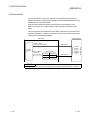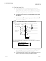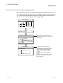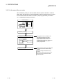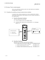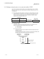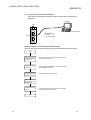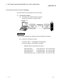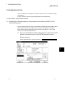
1
MITSUBISHI ELECTRIC MELSEC Q Programmable Logic Controllers User's Manual Communications Modules QD51(-R24) Art. no.: 142092 10 09 2000 SH-080089-B MITSUBISHI ELECTRIC INDUSTRIAL AUTOMATION • SAFETY PRECAUTIONS • (Always read these instructions before using this equipment.) Before using this product, please read this manual and the relevant manuals introduced in this manual carefully and pay full attention to safety to handle the product correctly. The instructions given in this manual are concerned with this product. For the safety instructions of the programmable controller system, please read the CPU module user's manual. In this manual, the safety instructions are ranked as "DANGER" and "CAUTION". DANGER Indicates that incorrect handling may cause hazardous conditions, resulting in death or severe injury. ! CAUTION Indicates that incorrect handling may cause hazardous conditions, resulting in medium or slight personal injury or physical damage. ! Note that the ! CAUTION level may lead to a serious consequence according to the circumstances. Always follow the instructions of both levels because they are important to personal safety. Please save this manual to make it accessible when required and always forward it to the end user. [DESIGN PRECAUTION] ! DANGER • Please refer to the manual for each data link concerning the operating status of each station when communications errors occur in the data link. There is danger of accidents due to wrong outputs or wrong operations. • When connecting a peripheral device to the CPU module or performing control of a PLC which is being run through a BASIC program, configure an interlock circuit in the sequence program so that the system overall is operating on the safe side at all times. Also, when performing other control (program modifications, changing the operating status (status control)) of a PLC that is currently running, read the manual thoroughly and proceed only after taking adequate safety precautions. Particularly in cases where the above control is performed toward PLC in remote locations from the opposite party's device, there may be occasions where it is impossible to respond immediately to trouble on the PLC side resulting from data communications errors. At the same time as you are configuring an interlock circuit in the sequence program, decide methods for the system to use to treat data communications errors between the opposite party's device and the PLC CPU. A-1 A-1 [DESIGN PRECAUTION] ! DANGER • Do not write data to the "System Area" in the intelligent function module's buffer memory. Also, do not turn the output for signals for "Use Prohibited" signals among the output signals from the PLC CPU to the intelligent function module (ON). If data are written to the "System Area" or output in response to "Use Prohibited" signals, there is danger that the PLC system will malfunction. ! CAUTION • Do not bunch the control wires or communication cables with the main circuit or power wires, or install them close to each other. They should be installed 100mm (3.94 in.) or more from each other. Not doing so could result in noise that may cause malfunction. • If a BASIC program is registered in the flash ROM in the module, do not perform a power OFF or PLC CPU reset operation at the station where the module is installed during registration. If a power OFF or PLC CPU reset operation is performed at the station where the module is installed during registration, the data contents in the flash ROM will be indefinite and it will be necessary to reset the setting values, etc. in the buffer memory and register them again in the flash ROM. It could also cause the module to break down or malfunction. [INSTALLATION PRECAUTIONS] ! CAUTION • Use the PLC in an environment that meets the general specifications contained in the user's manual of the CPU moudle to use. Using this PLC in an environment outside the range of the general specifications may cause electric shock, fire, malfunction, and damage to or deterioration of the product. • When installing the module, securely insert the module fixing tabs into the mounting holes of the base unit while pressing the installation lever located at the bottom of the module downward. Improper installation may result in malfunction, breakdown or dropping out of the module. Securely fix the module with screws if it is subject to vibration during use. A-2 A-2 [INSTALLATION PRECAUTIONS] ! CAUTION • Tighten the screws within the range of specified torque. If the screws are loose, it may cause the module to fallout, short circuits, or malfunction. If the screws are tightened too much, it may cause damage to the screw and/or the module, resulting in fall out, short circuits or malfunction. • Switch all phases of the external power supply off when mounting or removing the module. Not doing so may cause failure or malfunction of the module. • Do not directly touch the conductive area or electronic components of the module. Doing so may cause malfunction or failure in the module. [WIRING PRECAUTIONS] ! CAUTION • If the module is turned on and operated after installation or wiring operations, etc., be sure install the terminal cover provided with this product. If the terminal cover is not installed, there is danger of malfunction. • When connecting wires to the connector used for external connections, be sure to crimp, pressure weld or solder the wires correctly using the tool specified by the manufacturer. If connections are not perfect, it could result in short circuits, fire or malfunction. • Securely insatll the connector to the module. • Be sure to fix communication cables leading from the module by placing them in the duct or clamping them. Cables not placed in the duct or without clamping may hang or shift, allowing them to be accidentally pulled, which may cause a module malfunction and cable damage. • When connecting cables, be sure to do so correctly after confirming the type of interface you are connecting to. If connection is made to a different interface or if wiring is faulty, it could cause the module or external device to break down. • Tighten the terminal screws within the range of specified torque. If the terminal screws are loose, it may result in short circuits or malfunction. If the screws are tightened too much, it may cause damage to the screw and/or the module, resulting in the module falling out, short circuits or malfunction. • When disconnecting the communications cable or power cable that is connected to the module, do not disconnect it by grasping the cable with your hand and pulling it. Disconnect cables with connectors attached by taking hold of the connector at the connection with the module and pulling the connector. For cables connected to a terminal block, remove the cable after loosening the terminal block screws. If the cable is pulled while it is connected to the module, it could cause malfunction or damage the module or the cable. A-3 A-3 [WIRING PRECAUTIONS] ! CAUTION • Be careful not to let foreign objects such as swarf or wire chips get inside the module. They may cause fires, failure or malfunction. • In order to prevent the intrusion of foreign matter such as wiring debris inside the module during wiring, affix the label for preventing intrusion of foreign matter on the top of the module. Do not peel off this label during the wiring operation. Be sure to remove this label to allow heat to dissipate during system operation. [STARTING AND MAINTENANCE PRECAUTIONS] ! CAUTION • Do not disassemble or modify the each module. Doing so could cause failure, malfunction injury or fire. • Switch all phases of the external power supply off when mounting or removing the module. Not doing so may cause failure or malfunction of the module. • Do not touch the connector while the power is on. Doing so may cause malfunction. • Switch all phases of the external power supply off when cleaning or retightening terminal screws and module installation screws. Not doing so may cause failure or malfunction of the module. If the screws are loose, it may cause the module to fallout, short circuits, or malfunction. If the screws are tightened too much, it may cause damages to the screws and/or the module, resulting in fall out, short circuits or malfunction. [OPERATING PRECAUTIONS] ! CAUTION • When performing control (in particular, changing data, changing a program or changing the operation status (status control)) of the PLC during operation using a BASIC program, do so only after reading the user's manual thoroughly and taking adequate safety precautions. If there are errors when changing data, changing a program or in status control, it could result in system malfunction, or cause mechanical damage or accidents. [DISPOSAL PRECAUTIONS] ! CAUTION • When disposing of this product, treat it as industrial waste. A-4 A-4 REVISIONS The manual number is given on the bottom left of the back cover. Print Date Apr., 2000 Sep., 2000 Manual Number Revision SH(NA) 080089-A First printing SH(NA) 080089-B Addition Section 1.3, Section 2.3, 2.3.1, 2.3.2, 2.4 Japanese Manual Version SH-080092-B This manual confers no industrial property rights or any rights of any other kind, nor does it confer any patent licenses. Mitsubishi Electric Corporation cannot be held responsible for any problems involving industrial property rights which may occur as a result of using the contents noted in this manual. 2000 MITSUBISHI ELECTRIC CORPORATION A-5 A-5 INTRODUCTION Thank you for purchasing the MELSEC-Q series PLC. Before using the equipment, please read this manual carefully to develop full familiarity with the functions and performance of the Q series PLC you have purchased, so as to ensure correct use. CONTENTS 1 OVERVIEW 1- 1 to 1- 9 1.1 Operation Overview for QD51 (-R24)..................................................................................................... 1- 2 1.2 Features of QD51 (-R24) ........................................................................................................................ 1- 4 1.3 About the Function Added/Changed to the Function Version B ........................................................... 1- 9 2 SYSTEM CONFIGURATION AND USABLE FUNCTIONS 2.1 2.2 2.3 2.4 2.5 2- 1 to 2-11 Application Systems................................................................................................................................ 2- 1 Combining the Opposite Party's Device and the PLC CPU .................................................................. 2- 5 If the QD51 (-R24) is Used with a Remote I/O Station .......................................................................... 2- 7 If the QD51 (-R24) is Used in the QCPU (Function Version B)............................................................. 2-10 Checking the Function Version, Serial No. ............................................................................................ 2-11 3 SPECIFICATIONS 3- 1 to 3-57 3.1 Performance Specifications .................................................................................................................... 3- 1 3.2 RS-232 Interface Specifications ............................................................................................................. 3- 3 3.2.1 RS-232 connector specifications ..................................................................................................... 3- 3 3.2.2 RS-232 cable specifications............................................................................................................. 3- 4 3.3 RS-422/485 Interface Specifications ...................................................................................................... 3- 5 3.3.1 RS-422/485 terminal block specifications ....................................................................................... 3- 5 3.3.2 RS-422/485 cable specifications ..................................................................................................... 3- 6 3.3.3 Cautions during data communications with a RS-422/485 line...................................................... 3- 7 3.4 List of Commands and Functions in AD51H-BASIC.............................................................................. 3-10 3.5 QD51 (-R24) Internal Memory ................................................................................................................ 3-16 3.5.1 Program area.................................................................................................................................... 3-17 3.5.2 Buffer memory.................................................................................................................................. 3-19 3.5.3 Common memory............................................................................................................................. 3-21 3.5.4 Expansion register (ED0 to 1023) ................................................................................................... 3-23 3.5.5 Special register (ED9000 to ED9127) ............................................................................................. 3-26 3.5.6 Expansion relay (EM0 to EM1023).................................................................................................. 3-30 3.5.7 Special relay (EM9000 to EM9127)................................................................................................. 3-33 3.6 Receive Buffer......................................................................................................................................... 3-36 3.7 List of GPPW Setting Items for the QD51 (-R24) .................................................................................. 3-37 3.8 List of Input/Output Signals From/To the PLC CPU .............................................................................. 3-38 3.8.1 Input (X) detailed explanation .......................................................................................................... 3-39 3.8.2 Output (Y) detailed explanation ....................................................................................................... 3-42 A-6 A-6 3.9 Relationship between the QD51 (-R24) Start Condition and the Flash ROM Execution Program Area.......................................................................................................................................... 3-46 3.10 QD51 (-R24) Operation when the Power is Turned On ...................................................................... 3-47 3.10.1 In the case of the programming mode........................................................................................... 3-47 3.10.2 In the case of the multitask debugging mode ............................................................................... 3-48 3.10.3 In the case of the run mode ........................................................................................................... 3-49 3.11 Running a Task (a created program) ................................................................................................... 3-50 3.11.1 Conditions for permitting running of a task and start conditions................................................... 3-50 3.11.2 Starting by turning the power on or by reset (start condition: START) ........................................ 3-51 3.11.3 Starting by an interrupt from the PLC CPU (Start Condition: IT).................................................. 3-53 3.11.4 Starting by a start request from another BASIC program (Start condition: BOOT, ON) ............. 3-54 3.12 Running a BASIC Program by Multitask Processing........................................................................... 3-55 3.12.1 Multitask processing....................................................................................................................... 3-55 3.13 BASIC Program Priority Order (Priority)............................................................................................... 3-56 3.13.1 Synchronizing execution between BASIC programs (Event control) ........................................... 3-56 3.13.2 Sharing equipment (Resources) by multitasking .......................................................................... 3-57 4 ABOUT QD51 (-R24) FUNCTIONS 4- 1 to 4-24 4.1 List of Functions ...................................................................................................................................... 4- 1 4.2 Communications with a Console / Terminal........................................................................................... 4- 2 4.2.1 Connection with a console ............................................................................................................... 4- 3 4.2.2 Communications with a terminal...................................................................................................... 4- 6 4.3 Printing by a Printer................................................................................................................................. 4-10 4.3.1 Printing from a printer connected to an interface that is not set in the console ............................. 4-11 4.3.2 Printing from a printer connected to the console ............................................................................ 4-13 4.4 Communications with the External Device............................................................................................. 4-14 4.4.1 If data are being sent........................................................................................................................ 4-14 4.4.2 If data are received........................................................................................................................... 4-15 4.5 Communications with the PLC CPU ...................................................................................................... 4-16 4.5.1 ON/OFF data communications by general output (X/Y) ................................................................. 4-17 4.5.2 Reading and writing data from/to buffer memory............................................................................ 4-18 4.5.3 Reading and writing data from / to the PLC CPU ........................................................................... 4-19 4.5.4 Reading and writing data from/to the PLC CPU's expansion file register...................................... 4-20 4.6 Reading and Writing Data from/to the Buffer Memory of Another Intelligent Function Module/ Special Function Module ........................................................................................................................ 4-21 4.7 Reading and Writing Clock Data ............................................................................................................ 4-22 4.8 Data Communications Between Tasks .................................................................................................. 4-23 4.8.1 ON/OFF data communications by expansion relay (EM) ............................................................... 4-23 4.8.2 Data communications by expansion register (ED).......................................................................... 4-24 4.8.3 Data communications by common memory.................................................................................... 4-24 5 SETTINGS AND PROCEDURES UP UNTIL OPERATION 5- 1 to 5-18 5.1 Handling Precautions.............................................................................................................................. 5- 1 5.2 Settings and Procedures Up Until Operation ......................................................................................... 5- 2 5.3 Names of Parts and Functions ............................................................................................................... 5- 3 A-7 A-7 5.4 Connection with a Console, Debugger................................................................................................... 5- 4 5.5 Connection with the External Device...................................................................................................... 5- 6 5.5.1 Connecting to the RS-232 interface ................................................................................................ 5- 7 5.5.2 Connecting to the RS-422/485 interface ......................................................................................... 5- 9 5.6 Setting from the GX Developer............................................................................................................... 5-12 5.6.1 I/O assignment settings.................................................................................................................... 5-12 5.6.2 I/O module, intelligent function module switch settings .................................................................. 5-13 5.6.3 Intelligent function module interrupt point settings.......................................................................... 5-17 5.7 Maintenance, Checks ............................................................................................................................. 5-18 6 EXCLUSIVE COMMANDS 6- 1 to 6- 2 6.1 List of Exclusive Commands .................................................................................................................. 6- 1 6.2 YCHECK Command ............................................................................................................................... 6- 2 7 TROUBLESHOOTING 7- 1 to 7- 3 7.1 About QD51 (-R24) Status Checks ........................................................................................................ 7- 1 7.1.1 Checking the LED lighting status, communications error status and QD51 (-R24) switch setting status .................................................................................................................................... 7- 1 7.1.2 Errors that occur in BASIC............................................................................................................... 7- 3 APPENDIX App- 1 to App- 9 Appendix-1 Comparison of Functions with Previous Modules ................................................................AppAppendix-2 About Use of Programs from Previous Modules ..................................................................AppAppendix 2.1 About use of A1SD51S programs..................................................................................AppAppendix 2.2 About use of AD51H-S3 programs ................................................................................AppAppendix-3 External Dimensions .............................................................................................................AppINDEX A-8 1 2 2 5 8 Index- 1 to Index- 2 A-8 About Manuals The following manuals are also related to this product. In necessary, order them by quoting the details in the tables below. Related Manuals Manual No. (Model Name Code) Manual Name QD51/QD51-R2 Q Corresponding Intelligent Communications Module User's Manual (Hardware Manual) Explains the module's special function specifications and how to use them, and explains the settings for using the special functions and data communications methods with the opposite party's device. IB-0800130 (13JT05) (Included) AD51H-BASIC Programming Manual (Command Manual) (Corresponds to the QD51, QD51-R2, A1SD51S, AD51H-S3.) Explains the commands, how to use the functions and the specifications of AD51H-BASIC. SH-080094 (13JC05) (Sold separately) AD51H-BASIC Programming Manual (Program Manual, Compilation Manual) (Corresponds to the QD51, QD51-R2, A1SD51S, AD51H-S3.) Explains concerning debugging of AD51H-BASIC, multitasking settings, and compilation methods. (Sold separately) GPP Function Software Package SW5D5C-GPPW-E Operating Manual, Windows Edition Explains concerning online functions such as how to create programs, in SW6D5C-GPPW-E, printout methods, monitoring methods and debugging methods. SH-080093 (13JC06) SH-080059 (13JN66) (Sold separately) Conformation to the EMC Directive and Low Voltage Instruction For details on making Mitsubishi PLC conform to the EMC directive and low voltage instruction when installing it in your product, please see Chapter 3, "EMC Directive and Low Voltage Instruction" of the User's Manual (Hardware) of the CPU module to use. The CE logo is printed on the rating plate on the main body of the PLC that conforms to the EMC directive and low voltage instruction. A-9 A-9 How to read this manual, and Configuration How to use this manual We will explain concerning the QD51 (-R24) for each purpose of use. Use this manual for reference for the following contents. (1) When desiring to know the features, functions and component parts (a) When desiring to know the features and functions • The features of the QD51 (-R24) are described in Chapter 1. • The common specifications and functions, etc. of the QD51 (-R24) are described in Chapter 3. (b) When desiring to know the package contents and system component parts • The items included in the package when the QD51 (-R24) is purchased are described in "Product Configuration" before Chapter 1. • The user should procure parts and materials not included in the package contents separately. (2) When desiring to know the processing necessary to get the QD51 (-R24) started (a) When desiring to know the startup procedure • An abbreviated sequence of the procedures up to the point when the QD51 (-R24) is operated is described in section 5.2. (b) When desiring to know about connections with the console debugger • The connection method is described in section 5.4. (c) When desiring to know about connection with the opposite party's device • The connection method for each type of interface is described in section 5.5. (d) When desiring to know the processing necessary before the QD51 (-R24) is started up • Setting of the parameters used in the QD51 (-R24) using GPPW is explained in section 5.6. (3) When desiring to know about program application (a) When desiring to know about application of the program from the A1SD51S • Program application is described in section 2.1 of the Appendix. (b) When desiring to know about application of the program from the AD51H-S3 • Program application is described in section 2.2 of the Appendix. A - 10 A - 10 About the Generic Terms and Abbreviations In this manual, unless specially clarified, explanation of the Intelligent Communications Module using the general names and abbreviated names shown below. (1) Generic terms and Abbreviations of Affected Modules In this manual, PLC CPU units, etc. related to the Intelligent Communications Module are displayed with the following generic terms and abbreviations. When it is necessary to clarify the relevant model name, the affected module's model name is included. Generic Term/Abbreviation ACPU AnACPU AnNCPU Content of Generic terms and Abbreviations AnNCPU, AnACPU, AnUCPU A2ACPU, A2ACPU-S1, A2ACPUP21/R21, A2ACPUP21/R21-S1, A3ACPU, A3ACPUP21/R21 A1NCPU, A1NCPUP21/R21, A2NCPU, A2NCPU-S1, A2NCPUP21/R21, A2NCPUP21/R21-S1, A3NCPU, A3NCPUP21/R21 AnUCPU A2UCPU, A2UCPU-S1, A2USCPU-S1, A2USHCPU-S1, A3UCPU, A4UCPU AnA/AnU/QnACPU AnACPU, AnUCPU, QnACPU AnU/QnACPU AnUCPU, QnACPU QD51 Shows only the QD51. QD51-R24 Shows only the QD51-R24. QD51(-R24) Shows both the AD51 and QD51-R24. QCPU Q Mode Q02CPU, Q02HCPU, Q06HCPU, Q12HCPU, Q25HCPU A Mode Q02CPU-A, Q02HCPU-A, Q06HCPU-A QCPU-A QnACPU Q/QnACPU A - 11 Q2ACPU, Q2ACPU-S1, Q2ASCPU, Q2ASCPU-S1, Q2ASHCPU, Q2ASHCPU-S1, Q3ACPU, Q4ACPU, Q4ARCPU QCPU, QnACPU A - 11 (2) Other Generic terms and Abbreviations In this manual, serial communications module data communications devices, etc. are explained using the following generic terms and abbreviations. When it is necessary to indicate clearly what the object of the explanation is, the name / model name of that item is included. Generic Term/Abbreviation Buffer Memory CH GPPW I/F Intelligent Function Module Intelligent Function Module Device MELSECNET/10 MELSECNET/10H MELSECNET/10(H) Opposite device (external device) Programming Manual (Command Manual) or Command Manual Programming Manual (Program Editing, Compilation Manual) or Program Editing, Compilation Manual RS-232 (Interface) RS-422/485 (Interface) Special Function Module User's Manual (Hardware Manual) or Hardware Manual Content of Generic terms and Abbreviations Buffer memory of the intelligent function module for storing data sent to and received from the PLC CPU (setting values, monitor values, etc.). Channel GPP function software package SW6D5C-GPPW-E Windows Edition Interface Q series PLC module which runs according to commands from the PLC CPU. (Equivalent to a special function module of the A series PLC) (Examples) • CC-Link Interface Module • A/D, D/A Conversion Module • Ethernet Interface Module • Serial Communications Module Buffer memory of the intelligent function module for storing data sent to and received from the PLC CPU (setting values, monitor values, etc.). MELSECNET/10 network system. MELSECNET/10H network system. MELSECNET/10, MELSECNET/10H. Computer, display, measuring instrument, ID module, bar code reader, adjuster or other intelligent communications module, UC 24, etc. connected to this intelligent communications module for data communications. AD51H-BASIC Programming Manual (Command Manual) AD51H-BASIC Programming Manual (Program Editing, Compilation Manual) RS-232 compatible interface. RS-422 and RS-485 compatible interface. A/QnA series PLC modules operated by commands from the PLC CPU. (Equivalent to Q series PLC intelligent function modules.) (Examples) • CC-Link Interface Module • A/D, D/A Conversion Module • High Speed Counter Module • Ethernet Interface Module • Computer Link Module, Serial Communications Module Q Corresponding Intelligent Communications Module User's Manual (Hardware Manual) Microsoft Windows, Microsoft Windows NT, Microsoft Visual Basic and Microsoft Excel are registered trademarks of US Microsoft Corporation. PC-9800 and PC98-NX are registered trademarks of Nihon Electric Corporation. Other company names and product names appearing in this text are trademarks or registered trademarks of each respective company. A - 12 A - 12 Meanings of Terms and Their Contents The meanings of terms used in this manual and their contents are shown below. Term Contents This compiles programs created with the interpreter. It registers the compiled files and Compiler executes them. Compared to the interpreter, its execution speed is on the average 2 or 3 times faster. This is a device which connects to the QD51 (-R24) and is used to perform programming and multitasking settings. Console A DOS/V personal computer or a PC-9800 series personal computer with the software package installed becomes a console. Depending on the settings, the console becomes the debugger. This device connects to the QD51 (-R24) and performs debugging. A DOS/V personal Debugger computer or a PC-9800 series personal computer with the software package installed becomes the debugger. The debugger can check variable values and can edit the program while it is being run. Debugging Mode This mode changes the contents of variables and traces them while executing a program, and carries out tracing. This is the mode used when the console is disconnected and the QD51 (-R24) is Execution Mode being operated independently. It is actually used when this device is being run as a system. Interpreter Multitasking Programming Mode This is BASIC in a format which processes while executing commands one by one. This executes multiple programs by time slicing, executing them so that it seems that they are being executed simultaneously. This mode is used to connect to the console and carry out programming. This connects to the QD51 (–R24) and is used to display the screen and input Terminal characters from the keyboard. Product Configuration The QD51 (-R24) product configuration is as shown below. Model Name QD51 QD51-R24 A - 13 Product Name Quantity Model QD51 Intelligent Communications Module 1 Model QD51-R24 Intelligent Communications Module 1 Terminal Resistor 330 Ω, 1/4 W (For RS-422 communications) 2 Terminal Resistor 110 Ω, 1/2 W (For RS-485 communications) 2 A - 13 1 OVERVIEW MELSEC-Q 1 OVERVIEW 1 This manual explains concerning the system configuration, performance specifications and functions of the QD51 / QD51-R24 Intelligent Communications Module. The QD51 (-R24) has the following functions. (1) Functions by BASIC Programs • Sub-CPU Function Complex numerical calculations and function calculations can be made with a BASIC program. • Monitor Display Function It can display production conditions, the operating status the contents of a breakdown, etc. • Key Input Function The production schedule, production count, operation, setting data, etc. can be input. • Printer Function Production plans, results, daily schedules, breakdown contents, planning data, inspection results and test performance, etc. can be printed out. • Data Input Function Data input can be accomplished from a bar code reader or magnetic card reader, etc. • External Device Connection Function A computer, etc. can be connected to the RS-232, RS-422/485 interfaces and data can be sent and received through a BASIC program. • Clock Function Clock data held by the PLC CPU can be read and written. (2) Offline Programming Function BASIC programs can be created, corrected, stored to; user FD and printed out independently by peripheral devices. (3) Online Programming Function BASIC programs can be created, run, and corrected from the console. (4) Multitasking Debugging Function BASIC programs can be debugged while they are being run. 1-1 1-1 1 OVERVIEW MELSEC-Q 1.1 Operation Overview for QD51 (-R24) The QD51 (-R24) is a module which operates by BASIC programs created by the user. The BASIC version that can be used by the QD51 (-R24) is AD51H-BASIC, which is capable of multitasking processing of up to 2 tasks. Besides the various calculations that can be carried out by a BASIC program created by the user, • Data can be sent to and received from an external device. • Data can be sent to and received from the PLC CPU. The operation in the QD51 (-R24) when data are sent to or received from an external device or the PLC CPU is as shown below. Internal Memory Interface BASIC Program 1 RS-232 Expansion Relay Data reading Task No. 1 Area Data Writing Sending RS-232 Expansion Register External Device PLC CPU Common Memory Data Sending /Reception Data reading Data writing Buffer Memory RS-422 RS-485 Reception Task No. 2 Area • Data reading • Task start request • Interrupt request • Data writing 1 In the case of the QD51 RS-232 2 Channels In the case of the QD51-R24 RS-232 1 Channel RS-422/485 1 Channel 1-2 1-2 1 1 OVERVIEW MELSEC-Q (1) Sending Data to and Receiving Data from an External Device The QD51 (-R24) is equipped with the following interfaces. • QD51 : RS-232 2 Channels • QD51-R24 : RS-232 1 Channel, RS-422/485 1 Channel Non-procedure sending and reception of production instructions, production results and other data can be done between a personal computer or other external device connected to the RS-232 or RS-422/485 interface and the console. Production results and other data can also be printed out on a printer connected to the RS-232 interface. (2) Sending Data to and Receiving Data from the PLC CPU Through execution of the PLC Access commands (PCRD/PCWT) for sending data to and receiving data from the PLC CPU, PLC CPU device data can be read and written. With the PLC access commands, not only can reading and writing device data be done, but data can also be written to and read from a special function module, etc. 1-3 1-3 1 OVERVIEW MELSEC-Q 1.2 Features of QD51 (-R24) Systems which use the QD51 (-R24) have the features shown below. (1) It is possible to run up to two BASIC programs (tasks) simultaneously Since multitask processing is possible, it is possible to create BASIC programs where the control contents executed by the QD51 (-R24) are divided into processing modules. The necessary task is started in accordance with the control contents and the system can be controlled while carrying on data communications and synchronizing execution between each task. Control contents executed in the QD51 rding d acco Divide l contents tro to con Task 1 It is possible to create 3 or more BASIC programs. However, a maximum of 2 tasks (BASIC programs) can be run simultaneously. Task 2 (2) Data communications with external devices is possible <Data communications with external devices> Non procedure data communications can be carried out with external devices connected to the RS-232 and RS-422/485 interfaces. <Data communications with a console or terminal> Data can be displayed in a console or terminal connected to the RS-232 and RS422/485 interfaces and data can be input from the console or terminal. <Printout on a Printer> Data can be printed out on a printer connected to the RS-232 interface. Robot, bar code reader, thermostat, etc. QD51-R24 RUN PROG SD RD CH.1 ERR. P.RUN SD CH.2 RD DOS/V Personal Computer, etc. CH. 1 External device (printer) CH. 2 1-4 1-4 1 OVERVIEW MELSEC-Q (3) Data communications with the PLC are possible Data can be sent to and received from a PLC CPU or the MELSECNET/H PLC CPU with the QD51 (-R24) installed in it. The types of data which can be sent to and received from a PLC CPU are shown below. 1) Device writing and reading in the PLC CPU (Max. 960 words/1 time) 2) Writing to and reading from the buffer memory in the special function module (Max. 960 words/ 1 time). 3) Remote RUN/STOP of the PLC CPU. 4) Interrupts to the PLC CPU. (4) File control is possible Using the console's FD or HD (hard disk), sequential files and random files can be handled. However, it is necessary that the console be connected at all times. <Sequential Files> These are files in which data can be read and written sequentially and which enable efficient use of memory. They are used mainly for operating instruction data files and results files, etc. <Random Files> These are files where reading starts from the necessary portion only and only the necessary portion is written. This type of file is appropriate for large volume inventory files, instruction data for operator interfaces, master files, etc. When reading or writing is done one time, the maximum data size is 256 bytes. (5) Offline programming with a text editor is possible A BASIC program can be created offline using a text editor, and the BASIC program can then be registered. In offline programming, the edited program cannot be run. 1-5 1-5 1 OVERVIEW MELSEC-Q (6) Online Programming is possible By connecting the QD51 (-R24) to a DOS/V personal computer or a PC-9800 series personal computer and carrying out settings at a console, a BASIC program can be edited and debugged. In the case of programming with a DOS/V personal computer. RS-232 Cable QD51 QJ71E71 Q25HCPU MELSEC MODE RUN QD51-R24 ERR. RUN POWER COM.ERR INIT. OPEN SD CH1. CH2. RD ERR. CH1. 10BASE-T USER BAT. BOOT RS-232 10BASE FD for the user CH.3 SDA 1 SG PULL SDB (FG) USB RDA 2 3 4 (FG) RS-232 +12V RDB 12G RS-422 /485 MITSUBISHI 5 6 7 (7) Multitask debugging is possible By connecting the QD51 (-R24) to a DOS/V personal computer or a PC-9800 series personal computer and setting a debugger, debugging can be performed while performing multitask processing. In the case of programming with a DOS/V personal computer. RS-232 Cable QD51 QJ71E71 Q25HCPU MELSEC POWER MODE RUN RUN INIT. OPEN SD QD51-R24 ERR. COM.ERR CH1. CH2. RD ERR. CH1. 10BASE-T USER BAT. BOOT RS-232 10BASE CH.3 SDA 1 SG PULL SDB (FG) USB RDA 2 MITSUBISHI +12V RDB 12G RS-422 /485 FD for the user 3 4 (FG) RS-232 5 6 7 Multitask debugging is performed by inputting the Debug command from the debugger. By executing the Debug command, the following can be done. • The BASIC program for the specified task No. area can be run and terminated. • The variable values specified in the BASIC program for the specified task No. area can be read and written. • Data can be read from and written to the QD51 (-R24)'s internal memory. • Common events and message port use status displays, etc. can be shared between BASIC programs. (8) Both interpreter BASIC and compiled BASIC can be used By compiling a BASIC program created in interpreter BASIC with the BASIC compiler, the BASIC processing speed can be markedly increased. Interpreter BASIC : BASIC in an execution format where the QD51 (-R24) converts the program to machine language during execution. Compiled BASIC : BASIC in the format where the program is compiled (the commands are converted to machine language) at the stage when the program is completed and the QD51 (-R24) runs it in machine language directly. 1-6 1-6 1 OVERVIEW MELSEC-Q (9) Multiple PLC System Compatible Functions (a) If access to a QCPU in a multiple PLC system is done by a BASIC program, the access destination QCPU is specified, then reading/writing of device data is executed. If the QD51 (-R24) is used in a multiple PLC system, set the QCPU that controls the QD51 (-R24) (called the control PLC) with the GX Developer (SW6D5C-GPPW-E). It is also possible to install the Function Version A QD51 (-R24) in a multiple PLC system, and only the control PLC (PLC No. 1) can be accessed. Peripheral Device QD51 (-R24)'s Control PLC 1) 2) 3) 4) 1 2 1 QD 51 QD51 (-R24) Non control PLC Set from the SW6D5C-GPPW-E. 1) : PLC No. 1 2) : PLC No. 2 3) : PLC No. 3 4) : PLC No. 4 1 : Module controlled by PLC No. 1. 2 : Module controlled by PLC No. 2. (b) If the Function Version B QD51 (-R24) is used in a multiple PLC system, sending the following types of data to and receiving them from the QD51 (-R24) can be done. 1) It is possible for the control PLC to read data from and write them to the buffer memory. It is possible to use the I/O signals as the output to contact and output signal. 2) It is possible for a non control PLC to read the data from the buffer memory. Input/output signals can be used as contact points. Non control PLC Control PLC QD51(-R24) Buffer Memory FROM/TO Command Exclusive Command FROM Command Input/Output Signal used as a contact point. Input/Output Signal used as a contact point. Output to an output signal. X Y POINT In a multiple PLC system where the QD51 (-R24) is installed, only the QD51 (-R24)'s control PLC can use the QD51 (-R24)'s functions. 1-7 1-7 1 OVERVIEW MELSEC-Q 3) It is possible to access the Control PLC / Non Control PLC from the QD51 (-R24) by a BASIC program. Control PLC Non Control PLC QD51(-R24) BASIC Program (Read/Write) 03E0H to 03E3H 03FFH The access destination QCPU is specified by the requesting module's I/O No. Data Device Memory, etc. Data Device Memory, etc. If accessing another station by a BASIC program, even if the relay station or the access station is a multiple PLC system, the Control PLC and Non Control PLC of the access station can be accessed. (Example) Even if the control PLC of the relay module is the same, or even if it is different, it is possible to access the other station. Peripheral Device Local Station 1) 2) 3) 4) 1 2 1' Set from the SW6D5C-GPPW-E. MELSECNET/H Relay Station 1) 2) 3) 4) 2 2 MELSECNET/H Access Station 1) 2) 3) 4) 2 1) : PLC No. 1 2) : PLC No. 2 3) : PLC No. 3 4) : PLC No. 4 1 : Relay module controlled by PLC No. 1. 1' : QD51 (-R24) controlled by PLC No. 1. 2 : Relay module controlled by PLC No. 2. Relay Module: MELSECNET/H Network Module The relay module's object during other station access is as follows. • MELSECNET/H, MELSECNET/10 Network Module • Q Series C24 • Ethernet Interface Module If a Function Version A module is included in the relay modules, only the control PLC can be accessed. 1-8 1-8 1 OVERVIEW MELSEC-Q 1.3 About the Function Added/Changed to the Function Version B This shows the functions that have been added to or changed in the Function Version B QD51 (-R24). Function Multiple PLC system Compatibility Function overview When reading device data from or writing them to a multiple PLC system, it is possible to access the Control PLC / Non Control PLC specified by the user. Explanatory section AD51H-BASIC Programming Manual, PCRD/PCWT Command POINT (1) For a comparison of functions in the different function versions, see Section 1.1 in the Appendix. (2) See Section 2.4 concerning the method for checking the function version. 1-9 1-9 2 SYSTEM CONFIGURATION AND USABLE FUNCTIONS MELSEC-Q 2 SYSTEM CONFIGURATION AND USABLE FUNCTIONS This shows system configurations and the functions that can be used. 2.1 Application Systems 2 This shows application systems. (1) Applicable modules and the number of boards that can be installed This shows PLC stations in which the QD51 (-R24) can be installed and the number of boards that can be installed. Applicable Module CPU Module Remote I/O Station Number of Boards that can be installed Q02CPU Q02HCPU Q06HCPU Q12HCPU Q25HCPU Remarks Can be installed in the Q mode only. Maximum 64 boards QJ72LP25-25 QJ72BR15 MELSECNET/H Remote I/O Station (2) Base Unit where the QD51 (-R24) can be installed The QD51 (-R24) can be installed in any I/O slot ( 1) in the base unit. 1 This is limited to the permissible number of I/O points of the CPU module and remote I/O station. (3) Applicable Software Package Following shows the software package corresponding to QD51 (-R24) (a) Console/debugger software package (essential) Product Name AD51H-BASIC Software Package 2-1 Model Name Remarks SW1IVD-AD51HP For DOS/V Personal Computers SW1NX-AD51HP For the PC-9800 Series 2-1 2 SYSTEM CONFIGURATION AND USABLE FUNCTIONS (b) PLC software package (Essential) Product Name GX Developer 2 (c) MELSEC-Q Model Name SWnD5C-GPPW-E Remarks MELSEC PLC Programming Software The n in the model name is 4 or a higher number. Commercially available compilation software package (necessary only during compilation) 1) When using a DOS/V Personal Computer Purchase the product Borland C++ Suite. The Turbo Assembler is included in the Borland C++ Suite. Product Name Turbo Assembler Model Name Remarks Turbo Assembler Ver.5.0 IBM PC/AT English Version Inprise Corporation Setatsuka South Bldg. 1-64-8 Setatsuka, Shibuya-Ku, Tokyo 151-0073 Tel. 03-5350-9380 2) When using a PC-9800 Series Personal Computer Product Name Microsoft MASM (for the PC-9801 Series). Model Name Macro Assembler Ver6.0 Remarks For the PC-9800 Series, 1.25 MB format Microsoft Corporation Setatsuka NA Bldg. 1-50-1 Setatsuka, Shibuya-Ku, Tokyo 151-8533 Tel. 03-5454-8000 2-2 2-2 2 SYSTEM CONFIGURATION AND USABLE FUNCTIONS MELSEC-Q (4) Connection Cable for the Compiler/Debugger (a) When using a DOS/V Personal Computer 1) Connection Cables Combine cables to make connections. DOS/V Personal Computer QD51 QD51 CH.1 Conversion Cable FA-CBL25S9S or Conversion + Adapter FA-A25S9S RS-232 Cable AC30R2 Conversion Cable FA-CBL25S9P or Conversion + Adapter FA-A25S9P RUN ERR PROG P. RUN SD SD CH.2 RD RD CH.1 RS-232 CH.2 RS-232 (Introductory Product) (Introductory Product) QD51 CAUTION Two conversion adapters (FA-A25S9P) cannot be installed on the QD51. [Inquiries for Introductory Products] Conversion Cable : FA-CBL25S9S, FA-CBL25S9P Conversion Adapter : FA-A25S9S, FA-A25S9P Mitsubishi Electric Engineering Corporation East Japan Office Central Japan Office West Japan Office Kyushu Business Group 2) Fax Fax Fax Fax 09-3437-2676 052-541-2558 06-6347-2983 092-721-2109 Cable Wiring This shows wires for cables made by users. This Module Side Signal Name Tel. 03-3437-6103 Tel. 052-565-3435 Tel. 06-6347-2969 Tel. 092-721-2202 Pin No. Cable Connection and Signal Direction (Example of Full Duplex Communications Connection) Console Side Signal Name CD 1 CD RD(RXD) 2 RD(RXD) SD(TXD) 3 SD(TXD) DTR(ER) 4 DTR(ER) SG 5 SG DSR(DR) 6 DSR(DR) RS(RTS) 7 RS(RTS) CS(CTS) 8 CS(CTS) 9 CAUTION The pin arrangement on the console side may differ depending on the personal computer used. If the user makes the cables, please do so after confirming the personal computer's interface specifications. 2-3 2-3 2 SYSTEM CONFIGURATION AND USABLE FUNCTIONS (b) MELSEC-Q When a PC-9800 Series Personal Computer is used A connection cable cannot be used. The user should make a cable in accordance with the wiring for a cable made by the user. This Module Side Signal Name Pin No. Cable Connection and Signal Direction (Example of Full Duplex Communications Connection) Console Side Signal Name CD 1 CD RD(RXD) 2 RD(RXD) SD(TXD) 3 SD(TXD) DTR(ER) 4 DTR(ER) SG 5 SG DSR(DR) 6 DSR(DR) RS(RTS) 7 RS(RTS) CS(CTS) 8 CS(CTS) 9 CAUTION The pin arrangement on the console side may differ depending on the personal computer used. If the user makes the cables, please do so after confirming the personal computer's interface specifications. 2-4 2-4 2 SYSTEM CONFIGURATION AND USABLE FUNCTIONS MELSEC-Q 2.2 Combining the Opposite Party's Device and the PLC CPU This shows the system configuration and functions which can be used when the QD51 (-R24) is used. (1) System Configuration This shows the system configuration (combination) for data communications. (a) In the case of a 1:1 system configuration QJ71E71 Q25HCPU MELSEC POWER MODE RUN RUN INIT. OPEN SD ERR. USER QD51-R24 ERR. COM.ERR CH1. CH2. RD CH1. 10BASE-T BAT. BOOT RS-232 10BASE CH.3 SDA 1 SG PULL SDB USB 2 (FG) RDA 3 4 (FG) RS-232 MITSUBISHI +12V RDB 12G RS-422 /485 5 6 7 RS-232/422 (b) In the case of a n:1 system configuration QJ71E71 Q25HCPU MELSEC POWER MODE RUN RUN INIT. OPEN SD QD51-R24 COM.ERR CH1. POWER CH2. QJ71E71 Q25HCPU MELSEC ERR. MODE RUN RD ERR. CH2. CH1. BAT. BOOT RS-232 10BASE RS-232 CH.3 10BASE CH.3 SDA SDA 1 SG PULL SDB (FG) USB RDA +12V RDB 12G RS-422 /485 1 SG PULL 2 SDB USB 3 2 (FG) RDA 4 (FG) MITSUBISHI CH1. RD 10BASE-T USER BAT. BOOT RS-232 QD51-R24 ERR. COM.ERR RUN INIT. OPEN SD ERR. CH1. 10BASE-T USER 3 4 (FG) 5 RS-232 6 7 MITSUBISHI +12V RDB 12G RS-422 /485 5 6 7 RS-485 2-5 2-5 2 SYSTEM CONFIGURATION AND USABLE FUNCTIONS RUN POWER MODE (d) In the case of a m:n system configuration ERR. INIT. OPEN SD RUN In the case of a 1:n system configuration QD51-R24 QJ71E71 Q25HCPU MELSEC (c) MELSEC-Q COM.ERR CH1. CH2. RD ERR. CH1. 10BASE-T USER BAT. BOOT RS-232 CH.3 10BASE SDA 1 SG PULL SDB (FG) USB RDA 2 3 4 (FG) RS-232 MITSUBISHI 5 +12V RDB 12G RS-422 /485 6 7 RS-485 QJ71E71 Q25HCPU MELSEC POWER MODE RUN ERR. RUN INIT. OPEN SD POWER CH1. CH2. QJ71E71 Q25HCPU MELSEC QD51-R24 ERR. COM.ERR MODE RUN RD RUN INIT. OPEN SD ERR. USER CH1. 10BASE-T USER QD51-R24 ERR. COM.ERR CH1. CH2. RD CH1. 10BASE-T BAT. BAT. BOOT BOOT RS-232 RS-232 CH.3 10BASE 10BASE CH.3 SDA SDA SDB USB (FG) RDA MITSUBISHI +12V 12G RDB RS-422 /485 3 RDA 2 3 4 (FG) 4 RS-232 5 6 MITSUBISHI +12V RDB 12G RS-422 /485 5 6 7 7 RS-485 2-6 1 SG SDB (FG) USB 2 (FG) RS-232 PULL 1 SG PULL RS-485 RS-485 2-6 2 SYSTEM CONFIGURATION AND USABLE FUNCTIONS MELSEC-Q 2.3 If the QD51 (-R24) is Used with a Remote I/O Station This shows the case where the QD51 (-R24) is used with the MELSECNET/H Remote I/O station. POINT (1) If the QD51 (-R24) is used with the QCPU station, it is not necessary to read this section. (2) As for the MELSECNET/H (Remote I/O Net), the system can be built using the following QCPU (Q Mode). • Function version A QCPU (Q Mode) • QCPU (Q Mode) with serial No. 020920000000000 or later. (3) If the QD51 (-R24) is used with the MELSECNET/H remote I/O station, see the following manual in addition to this section. Q Corresponding MELSECNET/H Network System Reference Manual (Remote I/O Network Manual) (1) Remote I/O Stations in which the QD51 (-R24) can be installed. See section 2.1 concerning remote I/O stations in which the QD51 (-R24) can be installed. (2) System in the case where the QD51 (-R24) is used in a remote I/O station. (Example) (Remote Master Station) QCPU QJ71 LP21 -25 (Remote I/O Station) QJ72 QD51 LP25 (-R24) -25 MELSECNET/H Remote I/O Net QJ72 LP25 -25 (Remote I/O Station) 2-7 2-7 2 SYSTEM CONFIGURATION AND USABLE FUNCTIONS MELSEC-Q (3) Functions which can be used The functions which can be used when the QD51 (-R24) is installed in a remote I/O station are shown below. Usable Functions when Installed in Remote I/O Station Function Remarks See the AD51H-BASIC Programming Manual Communications by BASIC program ( 1) Multiple PLC System Compatibility For a remote I/O station, it is compatible with a single CPU system Communications via a BASIC program with a non-control PLC Multiple CPU settings through the GX Developer (SW6D5C-GPPW-E) : Can be used. : Cannot be used. 1 Functions which can be used by communications with the MELSECNET/H remote I/O station by BASIC program are as follows. Usable Function Function Reading and writing to device memory. Read, Write Reading and writing to intelligent function module buffer memory. Reading from and writing to the specified intelligent function module's buffer memory. Random read, random write The device range of a remote I/O station which can be accessed by reading from and writing to the device memory is as follows. (The same range as the QCPU when the default settings are set) Concerning the access device range with a remote I/O station device, see the AD51HBASIC Programming Manual. Device Name Device Symbol Device Name Device Symbol Special Relay SM Link Relay B Special Register SD Data Register D Input Relay X Link Register W Output Relay Y Link Special Relay SB Internal Relay M Link Special Register SW REMARK For a QnA/A Series Corresponding MELSECNET/10 Remote I/O: Station, only reading from and writing to the intelligent function module's buffer memory can be done. 2-8 2-8 2 SYSTEM CONFIGURATION AND USABLE FUNCTIONS MELSEC-Q (4) Setting from the GX Developer (SW6D5C-GPPW-E) In order to install the QD51 (-R24) in the remote I/O station, set the parameters from the SW6D5C-GPPW-E as follows. Each setting method is the same as when parameters are set for the QD51 (-R24) installed in the QCPU station. Carry out settings with reference to Section 4.5 and subsequent sections. For the method for displaying each setting screen, see the GX Developer (SW6D5C-GPPW-E) Operating Manual. (Parameter setting sections for the QD51 (-R24) when installed in a remote I/O station) Parameter Setting Item I/O Assignment I/O module, intelligent function module switch settings Setting Contents Remarks Sets the module installation information. See Section 4.5.1. Sets the console, debugger, etc. See Section 4.5.2. POINT (1) Connect the GX Developer (SW6D5C-GPPW-E) to the remote I/O station and set the parameters. (2) After changing the settings, carry out a remote I/O station reset operation. 2-9 2-9 2 SYSTEM CONFIGURATION AND USABLE FUNCTIONS MELSEC-Q 2.4 If the QD51 (-R24) is Used in the QCPU (Function Version B) This shows concerning access to the Non Control PLC in cases where the QD51 (-R24) is used in a multiple PLC system. For cases other than those shown below, see Section 2.1. (1) When accessing a non control PLC from the QD51 (-R24) by the functions shown in (2) below, use the following QD51 (-R24). (2) When accessing a non control PLC of a QD51 (-R24) from the QD51 (-R24) BASIC program by the following function, use a Function Version B QD51 (-R24). • If the BASIC program is accessing a non control PLC. (3) When the other station of the access destination is a multiple PLC system, if you are accessing via a non control PLC of the relay modules of the station you are accessing, use Function Version B modules for the local station, all the relay stations and the relay modules and QCPU of the station you are accessing. (Example) Even if the control PLC of the relay module is the same, or even if it is different, it is possible to access the other station. Peripheral Device Local Station 1) 2) 3) 4) 1 2 1' Set from the SW6D5C-GPPW-E. MELSECNET/H Relay Station 1) 2) 3) 4) 2 2 MELSECNET/H Access Station 1) 2) 3) 4) 2 1) : PLC No. 1 2) : PLC No. 2 3) : PLC No. 3 4) : PLC No. 4 1 : Relay module controlled by PLC No. 1. 1' : QD51 (-R24) controlled by PLC No. 1. 2 : Relay module controlled by PLC No. 2. Relay Module: MELSECNET/H Network Module 1 The relay module's object during other station access is as follows. • MELSECNET/H, MELSECNET/10 Network Module • Q Series C24 • Ethernet Interface Module POINT (1) A multiple PLC system can be built using QCPU (Q Mode) Function Version B. See Section 2.5 concerning the method for checking the function version. (2) If the QD51 (-R24) is used in a multiple PLC system, first see the User's Manual for the QCPU (Q Mode) multiple PLC system. 2 - 10 2 - 10 2 SYSTEM CONFIGURATION AND USABLE FUNCTIONS MELSEC-Q 2.5 Checking the Function Version, Serial No. This shows the method for checking the QD51 (-R24)'s function version and serial No. (1) Checking the Q Series PLC function version and serial No. (a) If you are checking the "Rating Plate" on the side of the module The serial No. and function version of the affected module are shown in the SERIAL column on the rating plate. MODEL Serial No. Function version SERIAL 020510000000000-B LISTED 80M1 IND. CONT. EQ. MADE IN JAPAN (b) If you are checking by GPPW This shows the method for checking the serial No. and function version of the affected unit if you are using SW6D5C-GPPW-E. The serial No. and function version are displayed on the "Product Information List" or the "Module Detailed Information" screen. The method for checking the serial No. and function version in the "Product Information List" screen is shown below. (See Section 10.1.1 concerning the "Unit Detailed Information" screen.) [Start Procedure] "Diagnosis" "System Monitor" "Product Information List" [Serial No., Ver] • The serial No. of the affected unit is displayed in the Serial No. column. • The function version of the affected unit is displayed in the Ver. column. 2 - 11 2 - 11 3 SPECIFICATIONS MELSEC-Q 3 SPECIFICATIONS This shows the performance specifications of the QD51 (-R24). For general specifications, see the ZCPU (Q Mode) User's Manual. 3.1 Performance Specifications The performance specifications of the QD51 (-R24) are shown below. Specification Item 3 QD51 QD51-R24 Programming Language AD51H-BASIC (Interpreter, Compiler) Number of Tasks 2 Task Start conditions • Start when power is turned on. • Start by an interrupt from the sequencer CPU. (Not possible when compiled BASIC is used.) • Start by a start request from another task. Internal Memory Program Max. 64 kBytes (Task 1 capacity + Task 2 capacity ≤ 64 kBytes) Common Memory 8 kBytes Buffer Memory 6 kBytes Expansion Relay (EM) 1024 points Expansion Register (ED) 1024 points General Input/Output Input: 27 points Output 23 points Memory Protection Interfaces None CH.1 RS-232 Compatible (D-sub 9p) CH.2 RS-232 Compatible (D-sub 9p) CH.3 Communications Method RS-232 Compatible (D-sub 9p) RS-422/485 (Two-piece terminal block) Full duplex communications Synchronization Method Start Stop Synchronization Transmission Rate (bps) 300, 600, 1200, 2400, 4800, 14,400, 19,200, 28,800, 38,400 It is possible to use the 2 interfaces with a total transmission rate within 38,400. Start Bit Data Format 7 or 8 Parity Bit Even, Odd, None Stop Bit 1 or 2 DTR/DSR (ER/DR) Control RS/CS Control Transmission Control 1 Data Bits RS-232 only can be used, RS-422/485 cannot be used. CD Signal Control None DC1/DC3 (Xon/Xoff Control) Both RS-232 and RS422/485 can be used. DC2/DC4 Control None Clock Function None Power Failure Maintenance None User Program ROM Storage The program area only can be stored in Flash ROM. Console DOS/V personal computer or PC-9800 series personal computer. Multitask Debugging Possible (when the debugger is used) (Continued from the previous page) 3-1 3-1 3 SPECIFICATIONS MELSEC-Q Specification Item Line Configuration ( 1 ) QD51 QD51-R24 RS-232 1:1 RS-422/485 Transmission Distance (Total Length Distance) 1 : 1, 1 : n, n : 1, m : n RS-232 Max. 15 m Max. 1200 m (Total Length Distance) RS-422/485 Connectable Stations Q series CPU (Q mode) Number of modules that can be installed per CPU. Number of points in an Input/Output Share Max. 64 boards (Can be installed within the number of input/output signals) 32 points (1-slot share) ( 2) 5 V DC Internal Current Consumption (A) 0.26 Flash ROM Writing Times Maximum 100,000 times for the same area. 0.31 3 Noise Tolerance Depends on the power supply unit of the installed station. Voltage Resistance Insulation Resistance External Dimensions (mm) 98 (H) Weight (kg) 27.4 (W) 90.5 (D) 0.20 RS-232 7/0.127 P HRV-SV External Diameter 8.5 mm or greater (Made by Oki Electric Wire (Corp.) Logarithm shown in the part) RS-422/485 SPEV (SB) –MC-0.2 3P External diameter approx. 6.5 mm (Made by Mitsubishi Electric Wire Co. Ltd.) SPEV (SB) -0.2 3P External diameter approx. 7.5 mm (Made by Mitsubishi Electric Wire Co. Ltd.) ( 3) Recommended Cables 1 This shows the combination when the opposite device and PLC CPU are connected. (Opposite Device Side: PLC CPU Side) The total n, m + n becomes a maximum of 32. 2 In order to use the QD51 (-R24), it is necessary to set the switch by GPPW. In order to set this switch, carry out a QD51 (-R24) I/O assignment (intelligent, 32 point) in GPPW. For the model name, set "QD51" or "QD51 (-R24)" corresponding to the module being installed. 3 The electrical characteristics of the recommended cables SPEV (SB) –MC0.2 3P and SPEV (SB) -0.2 3P are equivalent, but they differ somewhat in their external dimensions and internal wire colors. 3-2 3-2 3 SPECIFICATIONS MELSEC-Q 3.2 RS-232 Interface Specifications This shows concerning the RS-232 interface specifications. 3.2.1 RS-232 connector specifications The connector specifications for the RS-232 used to connect with the opposite device are shown below. Signal Abbreviation Pin No. 1 2 7 3 8 4 9 5 (1) 3-3 CD RD(RXD) 1 2 3 4 5 6 7 8 9 6 SD(TXD) DTR(ER) SG DSR(DR) RS(RTS) CS(CTS) Signal Direction Signal Name QD51 (-R24) Opposite Device Receive Carrier Detect Receive Data Transmit Data Date Terminal Ready Signal Ground Data Set Ready Request to Send Clear to Send Each control signal is explained below. (The connector pin No. is shown in parentheses.) 1) CD Signal (1) • Nothing is being controlled in the QD51 (-R24). • The signal status can be read by a BASIC program. 2) RD Signal (2) This is the signal for data reception. 3) SD Signal (3) This is the signal for data sending. 4) DTR Signal (4) • If DTR/DSR control is being exercised, the QD51 (-R24) is being turned On and Off depending on the size of the empty space in the OS area for storing reception data. When the DTR signal is OFF, reception data are being stored in the OS area, so read the reception data from a BASIC program. If DTR/DSR control is not being exercised, it is normally On. 5) DSR Signal (6) • If DTR/DSR control is being exercised, when Off, data are not sent to the opposite device from the QD51 (-R24). When the opposite device is in the ready to receive state, set it so that it is normally On. • If DTR/DSR control is not being exercised, the DSR signal's status is disregarded. 3-3 3 SPECIFICATIONS MELSEC-Q 6) RS Signal (7) • If RS/CS control is being exercised, the QD51 (-R24) is turned On or Off according to the size of the empty space in the OS area for storage of reception data. (It is On when data reception is possible.) When the RS signal is Off, reception data are being stored in the OS area, so read the reception data from a BASIC program. If RS/CS control are not being exercised, it is normally On. 7) CS Signal (8) • When Off, Data are not sent to the opposite device from the QD51 (-R24). • When the opposite device is in the ready to receive state, set it so that it is normally On. REMARK During data communications, the status of each control signal, DTR, DSR, RS and CD, can be checked with the ZCTRL command processing code 33. See the Programming Manual (Command Manual) concerning the ZCTRL command. (2) The On or Off status of each signal is shown when conditions are as follows. (Output Side) (Input Side) ON : 5 V DC to 15 V DC 3 V DC to 15 V DC OFF : 5 V DC to 15 V DC 3 V DC to 15 V DC (3) Connectors for Interface For the RS-232 interface connector on the QD51 (-R24) a product with the following model name is used. 9-pin D-sub (Female) screw fastened type DDK 17L-10090-27-D9AC For the connector shell on the connection cable on the QD51 (-R24) side, use one of the following products. (See Appendix 5 concerning the dimensions of connector shells that can be installed.) • Daiichi Electronics Industrial Co., Ltd. (Inquiries: Tel. 03-3494-8503) Plug, Shell Model Name: 17JE-23090-02 (D8A) • Sumitomo 3M Corporation (Inquiries: Tel. 03-3709-8503) Plug Model Name : 8209-6009 Shell Model Name : 3702-2209 M2.6 • Nihon AMP Corporation (Inquiries: Tel. 044-844-8111) Plug Model Name : 747904-2 Shell Model Name : 747515 or 174469-2 3.2.2 RS-232 cable specifications • For the RS-232 cable, use a cable which complies with the RS-232 standard and which has a length of 15 m or less. (Recommended cable) 7/0.127 P HRV-SV · · · : Specifies a logarithm (In the case of 13 pairs, 7/0.127 13P HRV-SV) (Made by Oki Electric Wire Co. Ltd.) 3-4 3-4 3 SPECIFICATIONS MELSEC-Q 3.3 RS-422/485 Interface Specifications This shows concerning the RS-422/485 interface specifications. 3.3.1 RS-422/485 terminal block specifications This shows the RS-422/485 terminal block specifications for connecting with the opposite device. SDA SG RDA (FG) RDB (1) (2) Signal Name SDA SDB RDA RDB SG FG FG Send Data (+) Send Data (-) Receive Data (+) Receive Data (-) Signal Ground Frame Ground Frame Ground SDB (FG) Signal Direction Signal Abbreviation QD51 (-R24) Opposite Device Each signal is explained below. 1) SDA, SDB Signal Signals for sending data to the opposite device from the QD51 (-R24). 2) RDA, RDB Signal Signals for receiving data from the opposite device by the QD51 (-R24). The function block diagram is shown below. (RS-422/485 Interface) 1 SDA + Send Data SDB - + Receive Data RDA RDB - 1 Connection of a terminal resistor is shown. Make connections in accordance with Section 5.5.2. 3-5 3-5 3 SPECIFICATIONS MELSEC-Q 3.3.2 RS-422/485 cable specifications This shows the RS-422/485 cable specifications. (1) For the RS-422/485 cable (cable which connects to the QD51 (-R24) terminal block), use a cable which satisfies the following specifications, with a length of 1200 m or less. (2) Also, when connecting multiple devices at 1:n, n:1, or m:n, keep the total cable length within 1200 m. (3) The RS-422/485 cable specifications are shown below. Item Content Cable Type Shielded Cable Logarism 3P Conductor Resistance (20°C) 88.0 Ω / km or less Insulation Resistance 10,000 MΩ - km or greater Voltage Resistance 500 V DC 1 minute Electrostatic Capacity (1 KHz) Average 60 nF/km or less Characteristic Impedance (100 KHz) 110 +/- 10Ω (Recommended Cables) SPEV (SB) – MPC –0.2 SPEV (SB) – 0.2 3P 3P : (Made by Mitsubishi Electric Wire Co. Ltd.) : (Made by Mitsubishi Electric Wire Co. Ltd.) The electrical characteristics of the recommended cables SPEV (SB) -MPC0.2 3P and SPEV (SB) -0.2 3P are equivalent, but they differ somewhat in their external dimensions and internal wire colors. 3-6 3-6 3 SPECIFICATIONS MELSEC-Q 3.3.3 Cautions during data communications with a RS-422/485 line Caution is necessary in the following points when carrying out data communications with the opposite device via the QD51 (-R24)'s RS-422/485 interface. As for the opposite device, please send and receive data with consideration of the following points. (1) Countermeasure for data error reception on the opposite device side when connected to the RS-422/485 When data containing errors are received by the opposite device, install a pull-up or pull-down resistor in the opposite device. By installing a pull-up or pull-down resistor (the criterion for the resistance value is approximately 4.7 kΩ, 1/4 W) it is possible to prevent reception of data containing errors. RDA 4.7kΩ1/4W Terminal RDB Resistor 4.7kΩ1/4W + Receiving Data - Opposite Device POINT If there is a pull-up or pull-down resistor in the opposite device, there will be no errors in the data which are received. REMARK Here, we will explain concerning cases where a pull-up or pull-down resistor is not installed in the opposite device. When no station is sending data, the send line switches to the high impedance state and noise, etc. cause the send line to drift, making it possible for the opposite device to receive data with errors in them. At such a time, it is possible that parity errors or framing errors, etc. could occur, so when an error occurs, skip over the data that are sent at such a time. 3-7 3-7 3 SPECIFICATIONS MELSEC-Q (2) RS-422/485 Interface Operation 1) SDR RS-422/485 Interface Configuration In the case of the RS-422-485 interface, the configuration of the QD51 (-R24) driver (Send) and receiver (Receive) are as shown in the following figure. Driver Send Data SDB RDA Output Control Input ( 1) Receiver Receive Data 1 The "Output Control Input" (also called the send gate) of the driver (Send) portion in the figure at left decides whether data from SDA or SDB are output to an external device or not output. RDB 2) RS-422/485 Interface Operation In the above figure, when the "Output Control Input" is in the ON state, it enters the low impedance state (the state in which data can be sent). Also, when the "Output Control Input" is in the OFF state, it enters the high impedance state (the state in which data are not being sent). 3) QD51 (-R24) send start timing and send processing end timing • Send start timing When sending data, after the high impedance state established by the operations shown in 1) and 2) above is canceled and after the mark is output, the actual data are output. • Send processing end timing After sending of data is completed, several µs are necessary for the H/W gate OFF time until the send processing is ended (changed to the high impedance state). (Output Control Input) Data Opposite Device Side QD51 (-R24) Side Data (Output Control Input) Mark output Data sending time range H/W Gate OFF time 3-8 “Output Control Input” ON time range (Low impedance state) “Output Control Input” OFF time range (High impedance state) The QD51 is in the data sending/reception enabled state. The QD51 is in the data reception enabled state. 3-8 3 SPECIFICATIONS MELSEC-Q POINT (1) When the configuration with the opposite device is n:1 or m:n If each respective device's send signal is connected as shown in the following figure, if the "Output Control Input" is in the ON state at 2 or more locations, data are output (sent) from the affected devices simultaneously. In order for data communications from the opposite device can be carried on normally, the following settings are necessary. • Set the "Output Control Input" so that it is in the ON state only when sending data. • Set the "Output Control Input" so that it is in the OFF state when data are not being sent. QD51-R24 SDA Send Data SDB Output Control Input Receive Data RDA RDB SDA Send Data SDB Output Control Input Opposite Device RDA RDB Receive Data SDA Send Data SDB Output Control Input Opposite Device RDA RDB Receive Data In the above wiring, sending and receiving are connected, the data sent by yourself is being received by yourself. Be sure to carry out programming so that such data are discarded by the BASIC program. 3-9 3-9 3 SPECIFICATIONS MELSEC-Q 3.4 List of Commands and Functions in AD51H-BASIC The commands in AD51H-BASIC which can be used by the QD51 (-R24) are shown in Table 4.2. (For details concerning each command and function, see the Programming Manual (Command Manual).) Table 3.1 List of Commands and Functions in AD51H-BASIC Classification Program creation preparations Program creation, correction commands Memory capacity read function Program editing Reading of the memory capacity Command, Function NEW Deletes the program in the program area and initializes all the variables. AUTO Displays the line No. at the head of the line automatically. CLEAR Initializes the variables and sets the memory area. DELETE Deletes the set program area. RENUM Renumbers the program line numbers. LIST Displays all or a portion of a given program in the program area. ZBAS Gives the number of the BASIC task No. area existing in the program that is currently being created or is being executed. FRE Gives the size of the unused area in the program area in number of bytes. RUN Program execution Program branching Format conversion command 3 - 10 Program debugging Reads a program from a memory card, or the FD or HD, and executes it. Restarts execution of a program that was stopped by a CTRL + C or BREAK key input. Restarts execution of a program that was stopped by the STOP or END command. CHAIN Erases or partially deletes the program that is currently being executed and reads out and executes the designated program. FOR to NEXT Repeats execution of a series of commands the designated number of times only. STOP When in the editing mode, it stops program execution temporarily and waits for input of a command. When in the execution mode, it it stops program execution and enters the idle state. END When in the editing mode, it stops program execution and waits for input of a command. When in the execution mode, it stops program execution and enters the idle state. WHILE to WEND Executes the group of commands between the WHILE and WEND commands repeatedly while the designated conditions are established. GOTO Moves the program flow unconditionally to the designated line. GOSUB to RETURN Branches to a subroutine, then returns to the designated line No. ON GOTO Branches to one line of a number of designated line numbers in accordance with the value. ON GOSUB Branches to one line of a number of designated line numbers in accordance with the value. IF GOTO ELSE Program debugging command Starts execution of the program in the program area. CONT Program control Program execution, control commands Operation Contents IF THEN ELSE Selects the branch destination in accordance with the results of a formula calculation. TRON Starts tracing of a program. TROFF Resets tracing of the program set by the TRON command. CDBI Converts double precision real numbers to 2-word (32 bit) integers used by the PLC CPU. CSNI Converts single precision real numbers to 2-word (32 bit) integers used by the PLC CPU. Format conversion 3 - 10 3 SPECIFICATIONS MELSEC-Q Table 3.1 List of Commands and Functions in AD51H-BASIC (Continued) Classification Command, Function Operation Contents Command to write to the designated bit Writing to the designated bit WTSET Writes 0 or 1 to the designated bit of an integer type array variable. Command to read from the designated bit Reading from the designated bit RDSET Reads 1 bit of data from the designated bit of an integer type array variable. Character ASCII ASC conversion CHR$ STR$ Character Number conversion VAL Number Character string conversion Character string functions Recognizes a numerical value as a decimal number and converts it to a character string. Gives a numerical value which shows a character string. Converts a decimal number to a hexadecimal character string. OCT$ Converts a decimal number to an octal character string. BIN$ Converts a decimal number to a binary character string. LEFT$ Fetches and gives a character string with the designated number of characters from the left of a character string. MID$ (Second) Gives a character string which is the starting portion from the designated position in the middle of a character string. RIGHT$ Fetches and gives a character string with the designated number of characters from the right of a character string. STRING$ Gives the designated number only of the designated character. SPACE$ Gives the a blank character string with the designated number of spaces. Character search INSTR Searches for a portion of a character string in the middle of a character string and gives the position where it is first found. Character string length search LEN Gives the number of characters composing a character string. Format control Format control function Screen control Screen control command SPC Gives the designated number of spaces. TAB Advances the current character display position to the designated position. CONSOLE Specifies the number of items displayed on the console screen. CLS Clears the screen display. LOCATE Specifies the display position on the console screen. ZOPEN Opens a communications port and prepares to execute communications with an external device. ZCLOSE Closes the channel of a communications port used in communications with an external device. BEEP Sounds a buzzer from the console's internal speaker. LLIST Outputs all or a portion of a program within the program area or the program in the specified range to a printer. Board assignment Buzzer output 3 - 11 Gives a character as a character code for the value of an integer formula. HEX$ Character sampling Input/Output Control Commands Gives a character code corresponding to the top character in a character string formula. Printer output LPRINT Outputs data to a printer. LPRINT USING Outputs data to a printer in the designated format. LFILES Outputs the name and size of a file to a printer. ZLDV Switches printer ports. WIDTH Sets the output width in the printer. PRINT Displays data on the screen. Output to screen PRINT USING Displays a character string or numbers in the designated format. KEY LIST Displays a character string defined in a function key on the screen. Output to port ZSEND Sends data from the designated port. 3 - 11 3 SPECIFICATIONS MELSEC-Q Table 3.1 List of Commands and Functions in AD51H-BASIC (Continued) Classification Input/Output Control Commands Input Functions Input from keyboard Input from port Changing of port settings Inputs from the keyboard Command, Function Operation Contents INPUT Inputs data from the keyboard. LINE INPUT Stores an entire line input from the keyboard (within 255 characters) in a character string variable without dividing it. ZRECEIVE Receives data from a communication port. ZCNTL Sets the currently open communications port and reads the communications port's status. INKEY$ If there is an input from the keyboard, the input characters are given, and if there is no input, space character strings are given. Character strings with lengths specified from the console keyboard are read and given. INPUT$ Character strings with lengths specified from sequential files are read and given. Character strings with lengths specified from the QD51 (-R24) communications port are read and given. Port Control Functions Port control Error Control Functions Error control Error Information Functions Error Information COM ON/OFF/STOP Controls enabling, prohibiting and stopping of interrupts from the communications line. ON COM GOSUB Defines the starting line of a processing routine for branching when an interrupt is generated from the communications line. ON ERROR GOTO Executes a program from the line number designated when an error occurs. ERROR Generates an error for the designated error code. ERR Gives the number of the error that was detected. ERL Gives the line number of the error that was detected. Recursive Commands to Recursion to the SYSTEM the programming mode Programming Mode Input / Output of BASIC programs File Operation Commands Interrupts control of the BASIC interpreter and returns to the QD51 (-R24)'s system mode. Interrupts offline programming and returns to the main menu. LOAD Reads out a program on a FD or HD into the program area. MERGE Mixes a program in the program area with a program on a FD or HD. SAVE Saves a program to a FD or HD. FILES Displays the file names of files on a FD or HD. Deletes files on a FD or HD. File maintenance KILL NAME Changes the file name of a program or data on a FD or HD. File bugger assignment OPEN Opens a file and enables input/output processing. CLOSE Closes input/output processing of a file. PRINT Writes data to a # sequential file. Deletes a system name on a FD or HD. PRINT # USING Designates the format in a sequential file and writes data. Sequential file input INPUT # / output Input / Output Commands to Files LINE INPUT # Reads an entire line (255 characters) from a sequential file to a character string variable without dividing it. FIFLD Allocates an area for the designated variable in a random file buffer. LSET Sets data left for the purpose of preparing the PUT command in a random file buffer. Random file input / output RSET 3 - 12 Reads data from a sequential file. Sets data right for the purpose of preparing the PUT command in a random file buffer. PUT Writes 1 record of data from a buffer to a random file. GET Reads 1 record of data from a random file to a buffer. 3 - 12 3 SPECIFICATIONS MELSEC-Q Table 3.1 List of Commands and Functions in AD51H-BASIC (Continued) Classification File information File information functions Character string Number File Data Command, Function EOF Gives a –1 if the end of a sequential file's end is detected. LOF Gives the size of a file in number of sectors. LOC Gives information on the current terminal position in a file. CVI Returns a character string converted by the MKI$ function to an integer. CVS Returns a character string converted by the MKS$ function to a single precision real number. CVD Returns a character string converted by the MKD$ function to a double precision real number CVSMBF Converts AD51H-BASIC single precision real numbers converted to character strings by the MKS$ function to internal expressions of floating point real numbers used in Q, QnA, AnA, AnU and AnUS (Single precision internal expressions in the IEEE format). CVDMBF Converts AD51H-BASIC double precision real numbers converted to character strings by the MKS$ function to double precision internal expressions in the IEEE format. MKI$ Converts integer type numbers to character strings. MKS$ Converts single precision type numbers to character strings. MKD$ Number Character string MKSMBF$ Definition, declaration commands Definitions, declarations Data operations Number, character string operation Substituting for commands variables Replacement of character strings 3 - 13 Operation Contents Converts double precision type numbers to character strings. Converts internal expressions of floating point real number data used in Q, QnA, AnA, AnU and AnUS (Single precision internal expressions in the IEEE format) to character strings that can be converted to numbers by the CVS function. MKDMBF$ Converts IEEE format double precision internal expression data to character strings that can be converted to numbers by the CVD function. DEF FN Defines user functions and assigns them names. DEFINT Defines variables starting with characters in the designated range as integer types. DEFSNG Defines variables starting with characters in the designated range as single precision real number types. DEFDBL Defines variables starting with characters in the designated range as double precision real number types. DEFSTR Defines variables starting with characters in the designated range as character types. KEY Defines a character string to be a console function key. DIM Designates the size of an array variable and allocates only the memory area that is necessary for the array. ERASE Deletes an array defined by the DIM command from memory. REM Gives a comment (annotation) in a program. COMMON Sets turnover variables, etc. in a program which executes CHAIN commands. DATA Designates a number or character string read by the READ command. READ Reads a value defined by the DATA command and substitutes it in a variable. RESTOR Reads the value of a DATA command read by the READ command from the first of a DATA command at the designated line No. LET Substitutes the value in a formula in a variable. SWAP Swaps the values of two variables. ZMOVE Transfers values between one variable and another variable. BSWAP Swaps two values in byte units. MID$ (First) Replaces a portion of a given character string with another character string. 3 - 13 3 SPECIFICATIONS MELSEC-Q Table 3.1 List of Commands and Functions in AD51H-BASIC (Continued) Classification Command, Function ABS Gives the absolute value of a mathematical expression. ATN Gives the inverse tangent (tan –1) of a mathematical expression. COS Gives the cosine value of a trigonometric function. EXP Gives the value of an exponential function with e as the base. FIX Rounds off the fraction portion of a number and gives the integer portion only. INT Gives an integer value of a mathematical expression. LOG Gives the value of a natural logarithm. Arithmetic functions RND Number functions Number search Gives a value with the bits rotated. SGN Gives the sign of a mathematical expression. SIN Gives the sine value of a trigonometric function. SQR Gives the value of a square root. TAN Gives the sine value of a trigonometric function. SHA Gives the memory contents of a designated value an arithmetically shifted value. SHT Gives the memory contents of a designated value a logically shifted value. SEARCH Searches for the designated value from the elements of the desired array variables, then gives the position of that element. CDBL Converts integers and single precision real numbers to double precision real numbers. CSNG Converts integers and double precision real numbers to single precision real numbers. Converts single precision real numbers and double precision real numbers to integers. CIDB Converts 2-word integers used in the PLC CPU (32 bit) to double precision real numbers. CISN Converts 2-word integers used in the PLC CPU (32 bit) to single precision real numbers. PCRD PLC access Gives a random number. ROT Format conversion CINT functions PLC access functions Operation Contents PCWT Reads all types of data from the PLC CPU. Writes all types of data to the PLC CPU. Operates the PLC CPU. ZIDV Carries out input through INPUT commands, etc. from the designated console. ZODV Carries out output through PRINT commands, etc. to the designated console. Buffer memory Buffer memory access access functions GETMEM Reads data from the QD51 (-R24)'s buffer memory, from common memory and from the expansion register (ED). PUTMEM Writes data to the QD51 (-R24)'s buffer memory, to common memory and to the expansion register (ED). Clock function Clock functions commands TIME$ Sets the time (Hr., Min., Sec.) in the PLC CPU and reads it out. DATE$ Sets the date (Yr., Mo, Day, Day of Week) in the PLC CPU and reads it out. ZEVENT Sets whether event generation will be enabled or disabled. Port switching commands Port switching DEF ZEVENT Real time control commands 3 - 14 Defines events for synchronization of execution between programs. Defines events according to the QD51 (-R24)'s expansion relay (EM). ZRELEASE Enables the use of resources with resource numbers allocated to them in other programs. ZRESERVE Prohibits the use of resources with resource numbers allocated to them in other programs. ZSIGNAL Generates an event designated from the program. ZSTART Starts the designated program. ZURGENCY Changes the priority of a program. Real time control 3 - 14 3 SPECIFICATIONS MELSEC-Q Table 3.1 List of Commands and Functions in AD51H-BASIC (Continued) Classification Real time control commands Real time control functions Japanese operation functions 3 - 15 Real time control Real time control Japanese character string operations Command, Function Operation Contents ZWAIT DELAY Interrupts execution of a program until the designated period of time passes. ZWAIT EVENT Interrupts execution of a program until the designated event occurs. ZMESSAGE Defines a message port. ZMESSAGE CLOSE Closes a message port. ZMESSAGE GET Reads a message from a message port. ZMESSAGE KILL Deletes a defined message port. ZMESSAGE OPEN Opens a message port. ZMESSAGE PUT Writes a message to a message port. AKCNV$ Converts single byte characters to double byte characters. JIS$ Gives the Kanji code of double byte characters. KACNV$ Converts double byte characters to single byte characters. KEXT$ Extracts double byte characters or single byte characters from a text expression and gives them. KINSTR Searches for the designated character string from character strings which include double byte characters and gives the position of the first character string that is found. KLEN Gives the number of characters of a character string that includes double byte characters. KMID$ Gives a partial character string that starts from the designated position in a character string that includes double byte characters. KNJ$ Gives double byte characters with the designated Kanji code. KTYPE Gives the type of characters at the designated position in a character string that includes double byte characters. 3 - 15 3 SPECIFICATIONS MELSEC-Q 3.5 QD51 (-R24) Internal Memory The following memory can be used by the user in the QD51 (-R24). (1) Memory where programs for execution can be stored • Program Area · · · · · · · · · · · · · · · · · · · · · · · · · · · · · · · · · · · · · See Section 3.5.1 This is memory where BASIC programs which run the QD51 (-R24) are stored. The program area can execute a maximum of two tasks and it has a maximum capacity of 64 k bytes. (2) Memory for communications with the PLC CPU • Buffer memory · · · · · · · · · · · · · · · · · · · · · · · · · · · · · · · · · · · · See Section 3.5.2 (3) Memory for communications with a task • Common memory · · · · · · · · · · · · · · · · · · · · · · · · · · · · · · · · · · See Section 3.5.3 (4) Memory for reading/writing ON/OFF data. • • • • Expansion register (ED) Special register (ED9000) Expansion relay (EM) Special relay (EM9000) : 1024 points(ED0 to ED1023) See Section 3.5.4 : 128 points (ED9000 to ED9127) See Section 3.5.5 : 1024 points(EM0 to EM1023) See Section 3.5.6 : 128 points (EM9000 to EM9127) See Section 3.5.7 CAUTION Internal memory is not backed up by a battery. If the QD51 (-R24)'s power is turned off, the BASIC program written to it and the data in the buffer memory, etc. are erased. Be sure to save the BASIC programs you create in flash ROM before turning the power off. Also, store the contents of buffer memory, etc. in a device that is latched by the PLC or save them to files. 3 - 16 3 - 16 3 SPECIFICATIONS MELSEC-Q 3.5.1 Program area Following programs can be stored in the program area: • BASIC programs created at the console • Programs for execution read from the flash ROM (1) Memory Capacity The program area's maximum capacity is 64 k bytes. This 64 k bytes is divided so it can be used for a maximum of 2 BASIC programs (Task 1 to Task 2). Task No. 1 Area (Max. 64 k bytes) Maximum 64 k bytes (total for 2 tasks) Task No. 2 Area (Max. 64 k bytes) (2) Capacity for 1 BASIC program The capacity for one BASIC program can be selected from 16 k bytes, 32 k bytes, 48 k bytes and 64 k bytes. CAUTION If compiled BASIC is used, approximately 2 times as much capacity is required as with interpreter BASIC. (3) Configuration for each Task No. Area Besides the area for the BASIC program, an OS area, an area for the variables used in that task and a random file buffer area are included in each Task No. Area. OS Area (1 k byte) BASIC Program Area One Task No. Area (16 k bytes, 32 k bytes, 48 k bytes and 64 k bytes) Random File Buffer Area Variable Area 3 - 17 3 - 17 3 SPECIFICATIONS MELSEC-Q POINT A program for running the flash ROM is read to the QD51 (-R24)'s program area in the following cases. (a) Program Mode When the power is turned on or when the QD51 (-R24) is reset. (b) Multitask Debugging Mode (c) Run Mode After the power is turned on or after a reset, when the RUN switch is in the RUN position. However, for an area where the multitask setting is set "ON", reading to the QD51 (-R24) is not done. QD51 (-R24) Program Area Program for running flash ROM 3 - 18 BASIC Task 1 Area START BASIC Task 2 Area ON BASIC Program Task 1 Area Task 2 Area 3 - 18 3 SPECIFICATIONS MELSEC-Q 3.5.2 Buffer memory Buffer memory is memory for carry out sending and receiving of data between the QD51 (-R24) and the PLC CPU. (Data from the PLC CPU that are written to buffer memory can be read from multiple tasks. Data written to buffer memory from multiple tasks can be read from the PLC CPU.) (1) Reading/Writing of Data (a) Data from the PLC CPU are read from or written to the buffer memory by the FROM/TO command. POINT If writing of data from the PLC CPU to buffer memory or reading of them from buffer memory, is performed, use the multitask execution start flag (X0B) as an interlock. Write Command X0B T0 H1 K0 D0 K1 Interlock that enables or disables FROM/TO execution. (b) In the QD51 (-R24), reading of data from, or writing of data to buffer memory is done using the GETMEM/PUTMEM command in the BASIC program. QD51(-R24) TO (Writing of data) PLC CPU FROM (Reading of data) Buffer Memory GETMEM (Reading of data) PUTMEM (Writing of data) BASIC program (2) Buffer Memory Capacity The capacity of the QD51 (-R24)'s buffer memory is 3 k words (6 k bytes). (3) Buffer Memory Configuration One address of the buffer memory is composed by 16 bits. The entire area can be used as desired by the user. REMARK (1) 3 - 19 See the AD51H-BASIC Programming Manual (Command manual) concerning the GETMEM and PUTMEM commands. 3 - 19 3 SPECIFICATIONS MELSEC-Q (4) Buffer Memory Addresses Addresses in buffer memory differ depending on whether they are designated by the PLC CPU or by a BASIC program, and are as follows. (a) If designated from the PLC CPU If designated by the PLC CPU, addresses are in 1-word units. Also, buffer memory addresses are designated from 0H to BFFH in hexadecimal notation. (b) If designated by a BASIC program If designated by a BASIC program, addresses are in 1-byte units. Also, buffer memory addresses are designated from 0H to 17FFH in hexadecimal notation. Designated from the PLC CPU using a FROM/TO command. (1-word units) Buffer Memory 0H 1H BFEH BFFH 3 - 20 Lower order 8 bits 0H Higher order 8 bits 1H Address designated by GETMEM / PUTMEM in a BASIC program. (1-byte units) Lower order 8 bits 2H Higher order 8 bits 3H Lower order 8 bits 17FCH Higher order 8 bits 17FDH Lower order 8 bits 17FEH Higher order 8 bits 17FFH 3 - 20 3 SPECIFICATIONS MELSEC-Q 3.5.3 Common memory Common memory is memory that can be used to send and receive data between the QD51 (-R24) internally and each task. Data from the PLC CPU can also be read and written using this memory. (1) Writing data to and reading data from common memory QD51(-R24) TO (Writing of data) PLC CPU FROM (Reading of data) GETMEM (Reading of data) Common memory PUTMEM (Writing of data) BASIC Program (a) In a BASIS program, data are read from or written to common memory using the GETMEM/PUTMEM command. (b) In a sequence program, data are read from or written to common memory using the FROM/TO command. (2) Common Memory Capacity In the QD51 (-R24), the size of common memory is 8 k bytes (3) Common Memory Configuration One address in common memory has a 1-byte (8 bits) configuration. The entire area can be used as desired by the user. 3 - 21 3 - 21 3 SPECIFICATIONS MELSEC-Q (4) Common Memory Addresses Addresses in common memory differ depending on whether they are designated by the PLC CPU or by a BASIC program, and are as follows. (a) If designated from the PLC CPU If designated by the PLC CPU, addresses are in 1-word units. Also, buffer memory addresses are designated from C00H to 1BFFH in hexadecimal notation. (b) If designated by a BASIC program If designated by a BASIC program, addresses are in 1-byte units. Also, buffer memory addresses are designated from 1800H to 37FEH in hexadecimal notation. Designated from the PLC CPU using a FROM/TO command. (1-word units) C00H C01H Buffer Memory 1800H Lower order 8 bits 1801H Address designated by GETMEM / PUTMEM in a BASIC program. (1-byte units) Higher order 8 bits 1802H Lower order 8 bits 1803H Higher order 8 bits 1BFEH 1BFFH Lower order 8 bits 37FCH Higher order 8 bits 37FDH Lower order 8 bits 37FEH Higher order 8 bits 37FFH REMARK (1) 3 - 22 See the AD51H-BASIC Programming Manual (Command Manual) concerning the GETMEM and PUTMEM commands. 3 - 22 3 SPECIFICATIONS MELSEC-Q 3.5.4 Expansion register (ED0 to 1023) The expansion register is internal memory where 1-word (16-bit) data can be stored. 1 If the expansion register is used, data can be stored internally in the QD51 (-R24) and 1-word data can be sent and received between tasks and between the QD51 (-R24) and the PLC CPU. 2 QD51(-R24) TO (Writing of data) Expansion Register PLC CPU FROM (Reading of data) W@/GETMEM (Reading of data) W@/PUTMEM (Writing of data) BASIC program (1) Writing data to and reading data from the expansion register Writing data to and reading data from the expansion register is accomplished by the special variable W@, or by the GETMEM/PUTMEM in a BASIC program, or by the FROM/TO command in a sequence program. The method of designating the expansion register differs in the W@ variable, the GETMEM/PUTMEM command and the FROM/TO command, as shown below. (a) Writing/Reading of data by the special variable W@ in a BASIC program With the special variable W@, the expansion register is designated by ED0 to ED1023. The designation is in 1-word units. QD51(-R24) Expansion Register b15 ED0 ED1 ED2 ED3 ED4 ED1021 ED1022 ED1023 3 - 23 to b0 W@ (Reading of data) BASIC program W@ (Writing of data) 3 - 23 3 SPECIFICATIONS MELSEC-Q REMARK 1) 1 The data in the expansion register are not backed up by a battery, so if the PLC's power is turned Off or it is reset, the data written to the register are erased. If it is necessary to save the data even when the PLC's power is turned Off or it is reset, save the data to a device that is latched to the PLC CPU's file register, etc. 2) 2 When data are sent and received between devices in 1-word units, the buffer memory (see Section 3.5.2) and common memory (see Section 3.5.3) can also be used. (b) Writing/reading of data by the PUTMEM/GETMEM command in a BASIC program With the GETMEM/PUTMEM command, the expansion register is designated by the address. The designated address is 3800H to 3FFFH in 1-byte units. QD51(-R24) Expansion Register b7 to b0 Lower order ED0 Higher order Lower order ED1 Higher order Lower order ED2 Higher order to ED1022 ED1023 (c) 3800H 3801H 3802H 3803H 3804H 3805H GETMEM (Reading of data) BASIC program to Lower order Higher order Lower order Higher order 3FFCH 3FFDH 3FFEH 3FFFH PUTMEM (Writing of data) Writing/Reading data by the FROM/TO command in a sequence program With the FROM/TO command, designate the expansion register by the address. The designation address is 1C00H to 1FFFH, in 1-byte units. QD51(-R24) TO (Writing of data) Sequence Program 1C00H 1C01H 1C02H 1C03H 1C04H 1C05H Expansion Register b7 to b0 Lower order Higher order Lower order Higher order Lower order Higher order to 1FFCH FROM 1FFDH (Reading of data) 1FFEH 1FFFH 3 - 24 ED0 ED1 ED2 to Lower order Higher order Lower order Higher order ED1022 ED1023 3 - 24 3 SPECIFICATIONS MELSEC-Q (2) During execution of a BASIC program by multitasking, data can be written or read from either task. Expansion Register (ED) ED0 Reading of data Writing of data Task 1 Task 2 (3) Number of Expansion Register Points The expansion register in the QD51 (-R24) is 1024 points, from ED0 to ED1023. (The expansion register No. in ED0 to ED1023 is expressed in decimal notation.) (4) Expansion Register Addresses Expansion register addresses are designated differently depending on whether they are designated by the PLC CPU or by a BASIC program, as shown below. (a) Designation from the PLC CPU If an address is designated by the PLC CPU, it is designated in 1-word units. Also, the buffer memory address is designated in hexadecimal notation, at addresses 1C00H to 1FFFH. (b) Designation from a BASIC program If an address is designated in a BASIC program, it is designated in 1-byte units. Also, the buffer memory address is designated in hexadecimal notation, at addresses 3800H to 3FFFH. Designated from the PLC CPU using a Buffer Memory FROM/TO command. Lower order 8 bits 3800H 1C00H (1-word units) Higher order 8 bits 3801H Lower order 8 bits 3802H 1C01H Higher order 8 bits 3803H 1FFEH 1FFFH 3 - 25 Address designated by GETMEM / PUTMEM in a BASIC program. (1-byte units) Lower order 8 bits 3FFCH Higher order 8 bits 3FFDH Lower order 8 bits 3FFEH Higher order 8 bits 3FFFH 3 - 25 3 SPECIFICATIONS MELSEC-Q 3.5.5 Special register (ED9000 to ED9127) The special register is a register which has its use determined by the QD51 (-R24). Data are stored by the QD51 (-R24)'s OS, so in a BASIC program, use the special variable W@ to read and use the stored data. Buffer Memory Special Address as seen from the Register No. CPU &H2400 &H2401 to &H2408 ED9000 ED9001 to ED9008 Name Content Details of Contents • The number of errors registered in the QD51 (-R24) is stored. Number of Errors 0 to 8 Error Code • Error codes are stored in order in ED9001 to ED9008. 0: Normal • If more than 8 error occur, the error codes Other than 0: are not stored. Error Code • For error codes, see the Programming Manual (Command Manual). Related Special Relay Related Special Register EM9000 ED9001 to ED9008 EM9000 ED9000 EM9000 ED9001 to ED9008 • The line No. of errors detected by BASIC are stored. • Correspondence between the error code and the special register for storing the line numbers is as shown below. &H2409 to &H2410 &H2414 3 - 26 ED9009 to ED9016 ED9020 0: No Line No. Error Line No. 1 to FFFF: Line No. Run Mode 0 to 4 For Error Code Storage For Line Number Storage ED9001 ED9009 ED9002 ED9010 ED9003 ED9011 ED9004 ED9012 ED9005 ED9013 ED9006 ED9014 ED9007 ED9015 ED9008 ED9016 • The setting number of the mode setting switch is stored. • 0, 1 : Run Mode • 2, 3 : Multitask Debugging Mode • 4 : Programming Mode 3 - 26 3 SPECIFICATIONS Buffer Memory Special Address as seen from the Register No. CPU MELSEC-Q Name Content Related Special Relay Details of Contents Related Special Register • The status of BASIC tasks 1 and 2 is stored as shown below. b15 to b8 b7 to 0 b0 0/10/1 BASIC Task 2 BASIC Task 1 0 &H2416 &H2032 3 - 27 ED9022 ED9050 BASIC task status PCRD, PCWT timeout time 0: BASIC task in • 0: BASIC task in the rest state the rest state (The BASIC program is not being run.) 1: • 1: BASIC task in the run state BASIC task in (The BASIC program is being run.) the run, BASIC task in the stopped state stopped or (None of the BASIC programs are being wait state run.) BASIC task in the wait state (Waiting for execution of the PRINT command or other command to be completed or a run interrupt command was executed.) • If a BASIC task is started by a ZSTART command, do so when the designated task is on bit "0". 0 to 32767 • This sets the timeout time of the PCRD and PCWT commands. (The default is 50 (5 sec.).) • Setting units: 100 ms • 0: Unlimited wait • 1 to 32767: 100 ms is the wait time 3 - 27 3 SPECIFICATIONS MELSEC-Q (1) Reading data in the special register Reading data from the special register is accomplished by the special variable W@ in a BASIC program, by the GETMEM command or by the FROM command in a sequence program. The method of designating the expansion register differs in the W@ variable, the GETMEM command and the FROM command, as shown below. (a) Reading of data by the special variable W@ in a BASIC program With the special variable W@, the special register is designated by ED9000 to ED9127. The designation is in 1-word units. QD51(-R24) Special Register b15 to b0 ED9000 ED9001 ED9002 ED9003 ED9004 W@ (Reading of data) BASIC program ED9125 ED9126 ED9127 (b) Reading of data by the GETMEM command in a BASIC program With the GETMEM command, the special register is designated by the address. The designated address is 4800H to 48FEH in 1-byte units. QD51(-R24) Expansion Register b7 to b0 4800H Lower order ED9000 4801H Higher order GETMEM 4802H (Reading of data) Lower order ED9001 4803H Higher order 4804H Lower order ED9002 4805H Higher order to ED9126 ED9127 3 - 28 BASIC program to Lower order Higher order Lower order Higher order 48FBH 48FCH 48FDH 48FEH 3 - 28 3 SPECIFICATIONS MELSEC-Q (c) Reading of data by the FROM command in a sequence program The special register is designated using the FROM command by the address. The designated address is 2400H to 24FEH, in 1-byte units. QD51(-R24) FROM (Reading of data) BASIC program Expansion Register b7 to b0 2400H Lower order ED9000 Higher order 2401H 2402H Lower order ED9001 2403H Higher order Lower order 2404H ED9002 Higher order 2405H to 24FBH 24FCH 24FDH 24FEH to Lower order Higher order Lower order Higher order ED9126 ED9127 (2) Special Register Addresses Special register addresses differ in the address designated depending on whether they are designated by the PLC CPU or by a BASIC program. Address designation is as follows. (a) Designation from a PLC CPU In the case of designation from a PLC CPU, designation is in 1-word units. Also, the special register address is 2400H to 247FH, in hexadecimal notation. (b) Designation by a BASIC program In the case of designation in a BASIC program, designation is in 1-byte units. Also, the special register address is 4800H to 48FFH, in hexadecimal notation. Designated from the PLC CPU using a Buffer Memory FROM/TO command. Lower order 8 bits 4800H 2400H (1-word units) Higher order 8 bits 4801H Lower order 8 bits 4802H 2401H Higher order 8 bits 4803H 247EH 247FH 3 - 29 Address designated by GETMEM / PUTMEM in a BASIC program. (1-byte units) Lower order 8 bits 4FFCH Higher order 8 bits 4FFDH Lower order 8 bits 4FFEH Higher order 8 bits 4FFFH 3 - 29 3 SPECIFICATIONS MELSEC-Q 3.5.6 Expansion relay (EM0 to EM1023) The expansion relay is a relay that can be used to send and receive ON/OFF data between tasks internally in the QD51 (-R24). It cannot be used to output data to external devices. (1) Turning the expansion relay On and OFF, and reading ON/OFF data (a) The special variable B@ can be used in a BASIC program to turn the expansion relay On and OFF and to read ON/OFF data. QD51(-R24) TO (Writing of data) PLC CPU FROM (Reading of data) (b) B@ (Reading ON/OFF data) Expansion Relay B@ (Writing ON/OFF data) BASIC program During BASIC program execution by multitasking, either task can read the ON/OFF data, and this register can be used by either task through a BASIC program. Expansion Relay (EM) EM0 : ON EM0 ON/OFF Task 1 EM0 ON/OFF Reading of data Task 2 (2) Number of Expansion Relay Points The QD51 (-R24) expansion relay has 1024 points. REMARK (1) For details on special variable B@, see the AD51H-BASIC Programming Manual (Command Manual). 3 - 30 3 - 30 3 SPECIFICATIONS MELSEC-Q (3) Writing/ Reading of Expansion Relay On/Off Data Writing On/Off data to and reading them from the expansion relay is accomplished using the special variable B@ or the GETMEM/PUTMEM command in a BASIC program, or using the FROM/TO command in a sequence program. The expansion relay designation method differs as follows in the B@ variable, the GETMEM/PUTMEM command and the FROM/TO command. (a) Writing On/Off data and reading them using special variable B@ in a BASIC program With special variable B@, the expansion relay is designated by EM0 to EM1023. Designation is in 1-bit units. QD51(-R24) Expansion Relay (b) EM0 EM1 EM2 EM3 EM4 1/0 1/0 1/0 1/0 1/0 (Reading of data) EM1021 EM1022 EM1023 1/0 1/0 1/0 (Writing of data) B@ BASIC program B@ Writing and reading data using the PUTMEM/GETMEM command in a BASIC program With the PUTMEM/GETMEM command, the expansion register is designated by the address. The address designated is 4700H to 477FH, in 1-byte units. QD51(-R24) Expansion Register b7 to b0 Lower order 4700H EM0 to EM15 Higher order 4701H 4702H Lower order EM16 to EM31 4703H Higher order 4704H Lower order EM32 to EM47 4705H Higher order to EM992 to EM1007 EM1008 to EM1023 3 - 31 GETMEM (Reading of data) BASIC program to Lower order Higher order Lower order Higher order 477CH 477DH 477EH 477FH PUTMEM (Writing of data) 3 - 31 3 SPECIFICATIONS MELSEC-Q (c) In the FROM/TO command for writing or reading data in accordance with the FROM/TO command of a sequence program, an expansion register is designated in the address. The designated address is in 1-byte units, from 2380H to 23BFH. QD51(-R24) TO (Writing of data) BASIC program 2380H 2381H 2382H 2383H 2384H 2385H Expansion Register b7 to b0 Lower order Higher order Lower order Higher order Lower order Higher order to FROM (Reading of data) 3 - 32 23BCH 23BDH 23BEH 23BFH EM0 to EM15 EM16 to EM31 EM32 to EM47 to Lower order Higher order Lower order Higher order EM992 to EM1007 EM1008 to EM1023 3 - 32 3 SPECIFICATIONS MELSEC-Q 3.5.7 Special relay (EM9000 to EM9127) The special relays are relays whose use is determined internally in the QD51 (-R24). On/Off control is performed by the QD51 (-R24) OS, so in each BASIC program, read the On/Off status using the special variable B@ to use these relays. Table 4.5 Special Relay List Buffer Memory Address as viewed from the CPU &H2500, bit 0 &H2502, bit 4 Special Relay No. Name Content Detailed Contents EM9000 Error ON : An error is registered. Registration OFF: No error is registered. Flag EM9020 Operation Flag Goes On when one of the following occurs. • Warning Error • Error Message • System Down Error Message Related Special Registers ED9000 to ED9016 • Goes On when the QD51 (-R24) is ON: Multitask execution in executing multitasks. progress • Goes OFF when the QD51 (-R24) is OFF: Task other than multitask executing a task other than multitasks. (1) Reading of Special Relay On/Off Data Reading of special relay On/Off data is accomplished by the special variable B@ or the GETMEM command in a BASIC program or by the FROM command in a sequence program. The expansion register designation method differs as shown below for the B@ variable, the GETMEM command and the FROM command. (a) Reading data by the special variable B@ in BASIC program With the special variable B@, the special registers are designated by EM9000 to EM9127. Designation is in 1-bit units. QD51(-R24) Special Relay 3 - 33 EM9000 EM9001 EM9002 EM9003 EM9004 1/0 1/0 1/0 1/0 1/0 EM9125 EM9126 EM9127 1/0 1/0 1/0 B@ (Reading of data) BASIC program 3 - 33 3 SPECIFICATIONS MELSEC-Q (b) Reading data by the GETMEM command in a BASIC program With the GETMEM command, special registers are designated by addresses. Designation addresses are 4A00H to 4A0FH, in 1-byte units. QD51(-R24) Expansion Relay b7 to b0 Lower order EM9000 to EM9015 Higher order Lower order EM9016 to EM9031 Higher order Lower order EM9032 to EM9047 Higher order 4A00H 4A01H GETMEM 4A02H (Reading of data) 4A03H 4A04H 4A05H to EM9096 to EM9111 EM9112 to EM9127 (c) BASIC program to 4A0CH 4A0DH 4A0EH 4A0FH Lower order Higher order Lower order Higher order PUTMEM (Writing of data) Reading data by the FROM command in a sequence program With the FROM command, special registers are designated by addresses. Designation addresses are 2500H to 2507H, in 1-word units. QD51(-R24) TO (Writing of data) BASIC program Expansion Register b7 to b0 Lower order 2500H Higher order Lower order 2501H Higher order Lower order 2502H Higher order to FROM (Reading of data) 2506H 2507H 3 - 34 EM0 to EM15 EM16 to EM31 EM32 to EM47 to Lower order Higher order Lower order Higher order EM992 to EM1007 EM1008 to EM1023 3 - 34 3 SPECIFICATIONS MELSEC-Q (2) Special Relay Addresses Special relay addresses differ in their designation as shown below depending on whether they are designated by the PLC CPU or by a BASIC program. (a) Designation from the PLC CPU If the address is designated from a PLC CPU, it is designated in 1-word units. Also, the address designated for the buffer memory address is 2500H to 2507H, in hexadecimal notation. (b) Designation in a BASIC program If the address is designated in a BASIC program, it is designated in 1-byte units. Also, the address designated for the buffer memory address is 4A00H to 4A0FH, in hexadecimal notation. Designated from the PLC CPU using a FROM/TO command. (1-word units) Buffer Memory 2500H 2501H 2506H 2507H 3 - 35 Lower order 8 bits 4A00H Higher order 8 bits 4A01H Address designated by GETMEM / PUTMEM in a BASIC program. (1-byte units) Lower order 8 bits 4A02H Higher order 8 bits 4A03H Lower order 8 bits 4A0CH Higher order 8 bits 4A0DH Lower order 8 bits 4A0EH Higher order 8 bits 4A0FH 3 - 35 3 SPECIFICATIONS MELSEC-Q 3.6 Receive Buffer The receive buffer is a memory buffer used for sending and receiving data between the QD51 (-R24)'s RS-232 interface and RS-422/485 interface and an external device connected to them. Control of the send/receive buffer is performed for each interface by the QD51 (-R24)'s OS. The receive buffer for each respective interface is 1024 bytes. The receive buffer stores data sent to the QD51 (-R24) from an external device, and when the INPUT or INKEY command is executed, the receive buffer's data are stored in the designated variable. QD51(-R24) External Device User Program PRINT, LPRINT command, etc. executed. BASIC program INPUT, INKEY command, etc. executed. Data reception Receive Buffer For CH1 1024 Bytes For CH2 1024 Bytes For CH3 1024 Bytes Data reception Console, terminal, printer, personal computer, etc. POINT The receive buffer's size can be changed by the AD51H-BASIC ZCNTL command. 3 - 36 3 - 36 3 SPECIFICATIONS MELSEC-Q 3.7 List of GPPW Setting Items for the QD51 (-R24) The following table shows a list of parameter setting items set using GPPW. Parameter Setting Item Parameter Contents Setting Contents Explanation Section Type I/O Allocation Setting Allocates I/O in the QD51 (-R24), and enables the following switch settings. Model name Number of points Section 5.6.1. Header X/Y Detailed settings Switch Settings Switch 1 Setting switch Switch 2 Mode switch Section 5.6.2 Switch 3 Switch 4 Not used (Set 0000H) Switch 5 Interrupt pointer header No. Interrupt Pointer Settings Multiple PLC Settings 3 - 37 Carries out settings in order to execute an interrupt program. Set when using a Multiple PLC system. CPU Side Number of interrupt pointers Intelligent module Side Header I/O No. Section 5.6.3 Header SI No. Number of CPU's , etc. See the QCPU (Q Mode) Multiple PLC corresponding user's manual 3 - 37 3 SPECIFICATIONS MELSEC-Q 3.8 List of Input/Output Signals From/To the PLC CPU The QD51 (-R24)'s input/output signals are explained. Allocation of input/output signals are shown for the case where the QD51 (-R24) is mounted in slot 0 of the basic base unit. Device X is an input signal from the QD51 (-R24) to a PLC CPU and device Y is an output signal from the PLC CPU to an intelligent communications device. The input/output signal list for the PLC CPU is shown in the following table. Device No. Signal Content Reference Section Device No. X0 Y0 X1 Y1 X2 Y2 X3 Y3 X4 Signal Content Reference Section Y4 X5 General input Section 3.8.1 (1) Y5 X6 Y6 X7 Y7 X8 Y8 X9 Y9 XA General Output Section 3.8.2 (1) BASIC Task 1 General output/ Start Task No. Designation BASIC Task 2 Section 3.8.2 (2) General Output Section 3.8.2 (1) YA 1 XB Section 3.8.1 (2) YB Multitask interrupt Section 3.8.1 (3) YC QD51 (-R24) system down Section 3.8.1 (4) YD XE QD51 (-R24) operating status Section 3.8.1 (5) YE XF Use prohibited XC 2 XD Multitask execution start YF X10 Y10 X11 Y11 X12 Y12 X13 Y13 X14 Y14 X15 Y15 X16 Y16 X17 General input X18 Section 3.8.1 (1) Y17 Y18 X19 Y19 Task Start Signal Section 3.8.2 (3) X1A Y1A Reset Request Signal Section 3.8.2 (4) X1B Y1B X1C Y1C X1D Y1D X1E Y1E X1F Y1F Use Prohibited 1 The multitask execution start signal (XB) is a signal that announces whether access to the QD51 (-R24) by the PLC CPU is possible or not. Use it as the system program interlock signal. (It goes ON when a BASIC program is run.) 2 If the QD51 (-R24) system down signal (XD) goes ON, start up the PLC CPU again. (Power supply reset, CPU module, QD51 reset) Important Do not output (turn On) the "Use Prohibited" signal, which is one of the input/output signals related to the PLC CPU. If an output is activated for the "Use Prohibited" signal, there is danger that the PLC system could malfunction. 3 - 38 3 - 38 3 SPECIFICATIONS MELSEC-Q 3.8.1 Input (X) detailed explanation Here, the input (X) for the QD51 (-R24) is explained. The input No. (Xn) used in this section is the No. as viewed from the PLC CPU. (1) General input (X00 to X0A, X10 to X1F: 27 points) The general input can be used freely by the user and can be used to send On/Off data from the QD51 (-R24) to the PLC CPU. Turning the general input On and Off is accomplished by the special variable B@. PLC CPU X00 QD51(-R24) General Input &H00 : ON Y100 Task 1 Task 2 B@ (X,&H00)=1 (2) Multitask execution start flag [X0B] (a) When the QD51 (-R24)'s mode setting switch 1 1 is set in the "Run Mode (0 or 1)", this flag is enabled (it carries out On/Off control). (If the QD51 (-R24) is in a mode other than the Run mode, it remains Off and does not change.) (b) If the QD51 (-R24) is in the Run mode, after the power is turned On or after a Reset, if multitask execution is enabled, this flag goes On. In a sequence program, use it as the interlock for execution or no execution of the FROM/TO command for reading data from/ writing data to the QD51 (-R24)'s buffer memory (see Section 6.6.5). (When the QD51 (-R24) is not in the multitask execution enabled state, if the FROM/TO command is executed for the PLC CPU, it will result in a "SP UNIT DOWN" error and the PLC CPU will stop its calculations.) 2 If data D0 is written from the PLC CPU to the QD51 (-R24)'s buffer memory address 0. Write Instruction X0B T0 H1 K0 D0 K1 FROM/TO command execution enable/disable interlock 3 - 39 3 - 39 3 SPECIFICATIONS MELSEC-Q (c) In the QD51 (-R24)'s Run mode, it is Off in the cases shown below. 1) When Y1A (reset request signal) of the QD51 (-R24) is turned On and reset is performed. (It goes On again if the QD51 (-R24)'s reset processing is completed and the multitask execution enabled state is restored.) 2) When a BASIC error is detected. (Multitask execution interrupt flag: X0C goes On.) BASIC Error detection OFF X0C X0B ON ON OFF 3) When the QD51 (-R24) system is down. (QD51 (-R24) down flag: X0D goes On.) QD51 System down X0D X0B ON OFF ON OFF REMARK (1) 1 See Section 4.1 and 4.2.1 concerning details of mode setting switch 1. (2) 2 If the QD51 (-R24)'s multitask execution start flag is turned Off by a Reset, if it is within the time when the set FROM/TO command access is enabled, it doesn't result in an error if the FROM/TO command is executed. (3) Multitask Execution Interrupt Flag [X0C] (a) When the QD51 (-R24)'s mode setting switch 1 is set in the "Run Mode (0 or 1)", this flag is enabled (it carries out On/Off control). (If the QD51 (-R24) is in a mode other than the Run mode, it remains Off and does not change.) (b) This flag goes On when an error is detected in a BASIC program during multitask execution. (At this time, the error steps and error code 1 are displayed by the LED indicator and the QD51 (-R24) enters the System mode. Correct BASIC programs where there are errors.) (c) If the multitask execution interrupt flag goes On, the multitask execution start flag (X0B) goes Off. BASIC Error detection OFF X0C X0B ON ON OFF 3 - 40 3 - 40 3 SPECIFICATIONS MELSEC-Q (4) QD51 (-R24) System Down Flag [X0D] (a) When the QD51 (-R24)'s mode setting switch is set in the "Run Mode (0 or 1)", this flag is enabled (it carries out On/Off control). (If the QD51 (-R24) is in a mode other than the Run mode, it remains Off and does not change.) (b) This flag goes On when the system goes down during multitask execution and an error is detected. At this time, an error code 1 will be displayed in the LED display. If Y1A (Reset request signal) goes On and the QD51 (-R24) is reset, the QD51 (-R24) down error can be canceled. (c) If the QD51 (-R24)'s system down flag goes On, the multitask execution start flag (X0B) will go Off. ON QD51 Down X0D X0B OFF ON OFF REMARK (1) 1 See Chapter 9 concerning the displayed error codes. (5) QD51 (-R24) Operating State [X0E] 3 - 41 (a) This shows the QD51 (-R24)'s operating state. (b) It goes Off during Power Off or during Reset processing. 3 - 41 3 SPECIFICATIONS MELSEC-Q 3.8.2 Output (Y) detailed explanation Here, QD51 (-R24) outputs (Y) are explained. The output No. (Yn) used in this section is the number as viewed from the PLC CPU. (1) General Output (Y00 to Y10: 17 points) The general outputs can be used to send On/Off data from the PLC CPU to the QD51 (-R24). In the PLC CPU, the general output can be turned On and Off by a sequence program or by the test function of a peripheral device, etc. In the QD51 (-R24), reading of general output On/Off data is accomplished by the special variable B@. QD51(-R24) PLC CPU Y00 Reading by the B@ command &H00 ON Task 1 Task 2 (2) Start Task No. Designation (Y11, Y12: 2 points) (a) These are signals which designate tasks to start by an interrupt from the PLC CPU and there is one point for each task. (b) The multitask setting becomes the start task No. designation signal for only tasks with "IT (start by an interrupt from the PLC CPU)" set. The device No. for a task for which the multitask setting is not set on "IT" is treated the same as a general output. Device No. Y11 Y12 3 - 42 Multitask Setting Start by an interrupt from the PLC CPU Start task No. setting Other than at left Task No. 1 General Output Task No. 2 (Impossible to start each task) (c) Turn the device No. (Y11, Y12) corresponding to the task you are starting On. At the time the task start signal (Y19) rises, the task thus designated to be turned On (Y11, Y12) will be started. However, if a task that is currently being executed is designated, it is disregarded. (d) To turn Off the signal designated by the start task No. that was turned On, do so only after confirming that the designate task has been executed. To check if the designated task has started, use the method of turning the general input (X) allocated to the Reset (Off) instruction by the BASIC program as shown in the example on the next page. 3 - 42 3 SPECIFICATIONS MELSEC-Q Example This example shows the procedure in the case where a task is started, and for turning the start task No. designated signal/task start signal Off. [Conditions] 1) Start Task No. ······ 1 2) Start task No. designation signal / Task start signal reset instruction ······ X11 Task start instruction 0 1 2 Slot No. Power QD51 Supply PLC CPU (-R24) module Task start completed Input/Output No. as seen from the PLC CPU: X/Y00 to X/Y1F Value designated by B@: X/Y&H00 to X/Y&H1F [Procedure] 1) Set the task No. · · · · · Turn Y11 On by a sequence program. 2) Start the task · · · · · · · Turn Y19 On by a sequence program. 3) Turn the Start Task No. designation signal / Task Start Signal Off · · · · · · Turn X&H11 On by a BASIC program. PLC CPU QD51(-R24) Task 1 Start Instruction PLS M0 Output 1) Set Task No. 1 M0 &H11 &H12 SET DY11 &H19 SET DY19 2) Start task. Start task No. 1 SET M1 B@ (X,&H11)=1 DX21 RST DY11 RST DY19 RST M1 3 - 43 3) Turn the Task No. designation signal / Task Start Signal Reset instruction On 3 - 43 3 SPECIFICATIONS MELSEC-Q (3) Task Start Signal (Y19) (a) This is a signal that starts the task designated by the start task No. designation signal (Y11, Y12). The task start signal cannot be used as a general output even in cases where there is no task that is started by an interrupt from the sequencer CPU. Also, if the task is compiled BASIC, it cannot be started by an interrupt from the PLC CPU. (b) The task start signal is enabled only while the multitask execution enable flag (X0B) is On. (c) The designated task 1 is started when the task start signal rises (Off On). (Even if the task No. designation signal goes On while the task start signal is On, it is disregarded.) Example The example shows a program in the case where task 1 is started from the PLC CPU. [Conditions] "IT (started by an interrupt from the PLC CPU)" is set with only task 1 set for multitasking. ON Task start signal Y19 OFF Task 1 start signal Y11 OFF ON ON 2 ON Y12 OFF ON 1 General output treatment Y13 OFF Task 1 starts ON Y18 OFF END Task 1 executed 1) 1 Since it is treated as a general output, starting of the task is not carried out. 2) 2 Since the task start signal is not changing from Off On, starting of task 1 is not carried out. [Sequence Program] Task 1 setting designation Y11 Task start command Y19 3 - 44 (d) In the case of the task designated by the start task No. designation signal (Y11, Y12) being in the process of starting, task start is disregarded. (Operation of the currently executing task is continued.) (e) If the exclusive command YCHECK is used, the task's starting time can be shortened. See Chapter 6 concerning the YCHECK command. 3 - 44 3 SPECIFICATIONS MELSEC-Q REMARK (1) 1 This is a task that corresponds to the device No. of the device designated by Y11, Y12 that is turned On. However, a device No. that does not have "IT (started by an interrupt from the PLC CPU)" set for the multitask setting is disregarded. (4) Reset Request Signal (Y1A) (a) This is a signal that resets the QD51 (-R24) module only. Reset is executed after the access enabled time following the Y reset set by the GPPW software switch. ON Reset request Y1A X0E OFF ON OFF Operating Wait for reset Resetting Operating Reset after access enabled time (200/2000 ms) following the Y reset set by GPPW. POINT During reset, set up an interlock with the QD51 (-R24) operating status signal (XE) so that there will be no access from a sequence program. 3 - 45 3 - 45 3 SPECIFICATIONS MELSEC-Q 3.9 Relationship between the QD51 (-R24) Start Condition and the Flash ROM Execution Program Area The start conditions for each task in multitasking have "BOOT" set when the BASIC program is stored in flash ROM by the system command MSAVE. If the start conditions are other than "BOOT", change it using the system command SET. The BASIC program's storage state in the program area differs as follows depending on the set start conditions. Start Condition Multitask Setting Started by Multitask execution Started by an interrupt from the PLC CPU Started by a start request from another task No multitask setting Symbol Area where the BASIC program to be run is stored START • Flash ROM run program area. (Designated BASIC task No. area) IT • Flash ROM run program area. (Designated BASIC task No. area) BOOT • Flash ROM run program area. (Designated BASIC task No. area) ON • User FD or HD file area for the peripheral device. (Save the BASIC program as a file.) BASIC Program Read Timing Reference Section Section 3.11.2 • In the System mode, when the power is turned on or during a Rest. Section 3.11.3 • In the Run / Multitask debugging mode, during multitask execution. Section 3.11.4 • When run by the ZSTART command. [The BASIC program with the file Section 3.11.4 name designated by the ZSTART command is read.] • Since there is no multitask setting, reading of a BASIC program is not done. OFF POINT The difference between the start condition "BOOT" and "ON" is as follows. • BOOT : The program to be run is stored in the designated BASIC task No. area in the main memory's program area. • ON : Only the memory capacity of the designated BASIC task No. area in flash ROM is set in the program area of the main memory and the program to be run is not stored in the BASIC task No. area. REMARK 1) 3 - 46 See the AD51H-BASIC programming manual (Programming Manual, Compilation Manual) concerning the system commands MSAVE and SET. 3 - 46 3 SPECIFICATIONS MELSEC-Q 3.10 QD51 (-R24) Operation when the Power is Turned On The QD51 (-R24) operates in the mode set by the software switch [Mode Setting] in GPPW when the power is turned On. Operation differs depending on the mode. 1) Programming Mode 2) Multitask Debugging Mode 3) Run Mode Here the operation of the QD51 (-R24) when the power is turned on is explained for each mode. 3.10.1 In the case of the programming mode When the QD51 (-R24) is in the Programming mode, when the power is turned On or when there is a Reset operation, the program to be run is read from the flash ROM and loaded in the QD51 (-R24)'s program area (See Section 3.5.1), then the mode is switched to the System Mode. 100 V AC/ 200 V AC PLC CPU Power turned On Power supply module Power turned On QD51 (-R24) Initialization processing Reading of the program to be run [QD51(-R24)] The program to be run is read from the flash ROM and loaded in the QD51 (-R24)'s program area. Program to be run Program area Flash ROM System mode [Console Display] Console operation is enabled in the system command reception state. S> 3 - 47 3 - 47 3 SPECIFICATIONS MELSEC-Q 3.10.2 In the case of the multitask debugging mode When the QD51 (-R24) is in the Multitask Debugging Mode, after the power is turned On or after a Reset, when the RUN key is in the RUN position, after the program to be run is read from the flash ROM and loaded in the QD51 (-R24)'s program area (see Section 3.5.1), the mode changes to the Debugging Mode. 100 V AC/ 200 V AC PLC CPU Power turned On Power supply module Power turned On QD51 (-R24) Initialization processing Reading of the program to be run [QD51(-R24)] The program to be run is read from the flash ROM and loaded in the QD51 (-R24)'s program area. Program to be run Program area Flash ROM System mode [Console Display] D> 3 - 48 It is possible to carry out multitask debugging by the debugger while in the Debug command reception state. Run the program read from the Flash ROM in accordance with the multitask setting contents. • Start by turning on the power or by a Reset. • Start by an interrupt from the PLC CPU • Start by a start request from another BASIC program. 3 - 48 3 SPECIFICATIONS MELSEC-Q 3.10.3 In the case of the run mode When the QD51 (-R24) is in the Run Mode, after the power is turned On or after a Reset, when the RUN key is in the RUN position, after the program to be run is read from the flash ROM and loaded in the QD51 (-R24)'s program area (see Section 3.5.1), multitask processing is executed. 100 V AC/ 200 V AC PLC CPU Power turned On Power supply module Power turned On QD51 (-R24) Initialization processing Reading of the program to be run [QD51(-R24)] Internal memory Program to be run Multitask processing 3 - 49 Flash ROM The program to be run is read from the flash ROM and loaded in the QD51 (-R24)'s program area. However, for a program with a task which has the multitask setting turned "On", the program is not read and loaded in the QD51 (-R24)'s program area. Run the program read from the Flash ROM in accordance with the multitask setting contents. • Start by turning on the power or by a Reset. • Start by an interrupt from the PLC CPU • Start by a start request from another BASIC program. 3 - 49 3 SPECIFICATIONS MELSEC-Q 3.11 Running a Task (a created program) Here, running a task when the QD51 (-R24) is in the Run Mode and in the Multitask Debugging Mode is explained. 3.11.1 Conditions for permitting running of a task and start conditions In the QD51 (-R24), a task is permitted to be run when it satisfies all the conditions shown below. (Actual starting of a task depends on the start conditions designated in the multitask setting.) (1) Task Run Permission Conditions Task start conditions are shown below. (a) The start conditions are set in the multitask setting. (b) The GPPW switch setting is set on "Online Mode (0, 1)" or "Debugging Mode (2, 3)". QD51 CH.1 RUN PROG SD RD ERR P.RUN CH.2 SD RD [Program] Stored in Flash ROM [GPPW Mode Setting] CH.1 RS-232 0, 1: Online Mode Task start conditions already set. 2, 3: Debugging Mode CH.2 RS-232 QD51 (2) Task Start Conditions Each task is run in accordance with the set start conditions. The start conditions that can be set by the QD51 (-R24) are following three types. 3 - 50 1) Start by turning on the power or by Reset : See Section 3.10.2. 2) Start by interrupt from the PLC CPU : See Section 3.10.3. 3) Start by a control command from another task : See Section 3.10.4. 3 - 50 3 SPECIFICATIONS MELSEC-Q 3.11.2 Starting by turning the power on or by reset (start condition: START) This is the case where the start condition in the multitask setting is set on "START". Starting of a task is done if the "Run Permission Conditions" listed in Section 3.10.1 are established. (1) Processing when the power is turned on or when there is a reset When the power is turned On or there is a Reset, after the program to be run which is stored in the Flash ROM is read and loaded to the QD51 (-R24)'s program area, the designated task is run. Flash ROM QD51 (-R24) BASIC Task No. Area Start Condition 1 START Task No. 1 Area 2 START Task No. 2 Area BASIC Program Program Area (2) Running a Task A task that is started by the power being turned On or by a Reset is run as follows in accordance with the BASIC program that is created. 1) Run once only. 2) Run all the time. (a) If it is run once only A program is run once only if the "END" command is written at the end of the BASIC program. The task starts when the power is turned On or when there is a Reset, and operation stops at the point when the END command is run. Power On Reset BASIC Program END 3 - 51 Task with "START" set in the start condition. BASIC program stops. 3 - 51 3 SPECIFICATIONS MELSEC-Q (b) If the program runs all the time The program runs all the time if an END command is not used at the end of the BASIC program, but instead a "GOTO" command is used to cause it to jump to a specific line. The task starts when the power is turned On or when there is a Reset, then runs until the GOTO command, then since it jumps to the specified line, it runs repeatedly between the specified line and the GOTO command. Power On Reset BASIC Program BASIC Program Task with "START" set in the start condition. GO TO 3 - 52 3 - 52 3 SPECIFICATIONS MELSEC-Q 3.11.3 Starting by an interrupt from the PLC CPU (Start Condition: IT) This is the case where the start condition in the multitask settings is set on "IT". Starting of a task is done if the "Run Permission Conditions" listed in Section 3.11.1 are established and when there is a start request from the PLC CPU. A start request from the PLC CPU is executed by: 1) Start task No. designation flag (Y11, Y12). 2) Task start signal (Y19). (For details concerning the start task designation signal and the task start signal, see Section 3.8.2.) (1) Processing when the power is turned On or when there is a reset When the power is turned On or there is a reset, the program to be run which is stored in Flash ROM is read and loaded into the QD51 (-R24)'s internal memory. The loaded BASIC program is then run when there is a start request from the PLC CPU. (2) Running a task (a) When the power is turned On or there is a reset, the Basic program that is read from the Flash ROM is started by a task start signal from the PLC CPU to the QD51 (-R24). When the task start signal rises, the task with the start task No. designation flag On is started. Start request from PLC CPU BASIC Program Task with IT set in the start condition. END (b) BASIC program stops. For a task that is started by an interrupt from the PLC CPU, write it so that an "END" command is run at the end of the BASIC program. If an "END" command is run, the interrupt from the PLC CPU is reset and it is made possible for the next interrupt to be received. POINT When using compiled BASIC, "IT" cannot be set in the start condition. 3 - 53 3 - 53 3 SPECIFICATIONS MELSEC-Q 3.11.4 Starting by a start request from another BASIC program (Start condition: BOOT, ON) This is the case where the start condition in the multitask settings is set on "BOOT" or "ON". Starting of a task is done if the "Run Permission Conditions" listed in Section 3.11.1 are established and when there is a start request by the ZSTART command from another BASIC program. (For details of the ZSTART command, see the AD51H-BASIC Programming Manual (Command Manual).) (1) Processing when the power is turned On or when there is a reset (a) In the case of the start condition "BOOT", when the power is turned On or there is a reset, the program to be run which is stored in Flash ROM is read and loaded in the QD51 (-R24)'s internal memory. The BASIC program is run when there is a start request from another task. (b) In the case of the start condition "ON", when the power is turned On or there is a reset, the program to be run which is stored in Flash ROM is not read and loaded in the QD51 (-R24)'s internal memory. When there is a start request from another task, the designated BASIC program is read from the file area of the user FD/HD and run. (2) Running a task (a) If the start condition is "BOOT", the task starts when the "ZSTART" command is run from another BASIC program. If the start condition is "ON", the task starts each time the "ZSTART" command is run from another BASIC program and the designated BASIC program has been read from the user FD/HD file area. [If the start condition is "BOOT"] [If the start condition is "ON"] Start request from another BASIC program Start request from another BASIC program BASIC Program BASIC program is read from the user FD/HD. END • BASIC Program stops. • Start request is reset. BASIC Program END (b) 3 - 54 • BASIC Program stops. • Start request is reset. For a task that is started by a start request from another BASIC program, write it so that an "END" command is run at the end of the BASIC program. If an "END" command is run, the start request is reset and it is made possible for the next interrupt to be received. 3 - 54 3 SPECIFICATIONS MELSEC-Q 3.12 Running a BASIC Program by Multitask Processing Here, the method of running a QD51 (-R24) BASIC program, etc. is explained. 3.12.1 Multitask processing The QD51 (-R24) us a unit which operates by BASIC programs created by the user. In the QD51 (-R24), through multitask processing in which running of multiple (a maximum of 2 tasks) BASIC programs is switched sequentially by a single main CPU (Central Processing Unit), BASIC programs are run in parallel. Example [Processing in the case of two tasks] Shows the order of main CPU processing. Task 1 Task 2 1) 2) 3) 4) 5) 6) In QD51 (-R24) multitask processing, switching of BASIC program execution is done when the conditions shown below occur. • When "Task schedule time (50 ms)" has passed. • When a data input/output (data send/receive) command is run with respect to a screen, keyboard, disk, peripheral device or external device. • When a command is run which carries out control of (interrupts, stops, ends) BASIC program execution. • When a command is run which carries out multitask control (synchronizes execution, starts or changes the priority, etc.). • When a program execution interrupt state is canceled (input/output is completed, the specified time has passed, etc.) REMARK 1) 3 - 55 See the AD51H-BASIC Programming Manual (Command Manual) concerning details of multitask processing and commands which switch the execution of programs. 3 - 55 3 SPECIFICATIONS MELSEC-Q 3.13 BASIC Program Priority Order (Priority) In the QD51 (-R24), a priority order (priority) can be assigned to BASIC programs that are created. When BASIC programs are started, all BASIC programs are set at the same priority order. Therefore, the BASIC programs created by the user are run equally. The priority order can be changed by the ZURGENCY (Set urgency) command. If the priority order is changed, as long as a program execution switch command is not run, only the BASIC program with the highest priority is run without any scheduling being done by the OS. (BASIC programs with a low priority are not run.) 3.13.1 Synchronizing execution between BASIC programs (Event control) In multitask processing, each BASIC program is process independently. for this reason, if data are shared between BASIC programs, it is necessary that the receiving side read the data after confirming that the sending side has sent the data. Event control is used to synchronize the execution of the data sending side BASIC program and the data receiving side BASIC program. In event control, the BASIC program that is on the data receiving side is set in the signal wait (WAIT) state then after the sending side finishes sending the data, it gives a signal (event) and the receiving side BASIC program reads the data. For this reason, the data sent by the sending side can be read precisely by the receiving side BASIC program. In event control, the following commands are executed. • DEF ZEVENT : Definition of the event. • ZEVENT ENABLE : Enabling generation of the event. • ZWAIT EVENT : Waiting for the event. • ZSIGNAL : Generating the event. REMARK 1) 3 - 56 See the AD51H-BASIC Programming Manual (Command Manual) concerning details on event control and the commands used. 3 - 56 3 SPECIFICATIONS MELSEC-Q 3.13.2 Sharing equipment (Resources) by multitasking If use of resources is shared by BASIC programs, the same resources cannot be used by multiple BASIC programs at the same time. Exclusive control of resources is a way of making it impossible for another BASIC program to use resources while one BASIC program is using them. This exclusive control of resources must in the end be decided and implemented by fellow programmers. If this problem is not decided by the fellow program creators and therefore not provided for, exclusive control of resources cannot be implemented. Exclusive control of resources is accomplished by the following commands. • ZRESERVE : Requests exclusive control of a resource. • ZRELEASE : Ends exclusive control of a resource. REMARK 1) 3 - 57 Resources are said to be all the hardware and software that can be used by a BASIC program. For example, the screen, printer, files, disks or memory, etc. 3 - 57 4 ABOUT QD51 (-R24) FUNCTIONS MELSEC-Q 4 ABOUT QD51 (-R24) FUNCTIONS Here, the functions possessed by the QD51 (-R24) are explained. 4.1 List of Functions A list of QD51 (-R24) functions is shown below. Item Content 1) Sub-CPU Function Complex numerical calculations and function calculations which would lengthen the PLC CPU' s scan time can be calculated by a BASIC program. • Collection, analysis and correction of measurement data • Function calculations such as Sine, Log and square roots, etc. Monitor Display Function This displays the operating status (production conditions, running status, breakdown contents, etc.) in a console or terminal connected to the QD51 (-R24). Section 4.2 Key Input Function This carries out input of production schedules, production quantity, operations, setting data, etc. from the keyboard of a console or terminal connected to the QD51 (-R24). Section 4.2 This prints out production plans, results, daily reports, breakdown contents, planning data, inspection results, test results charts, etc with a printer connected to the QD51 (-R24). Section 4.3 Functions by BASIC Printer Function programs Data Input Function This enables input of data from a bar code reader or magnetic card reader, etc. that is connected to the QD51 (-R24). (Since sending and receiving can be done in a free format through a BASIC program, it is possible for the QD51 (-R24) to match the protocols of the opposite device.) • Input of production lot No., product name, quantity, etc. • Collection of measured values, test data. This connects with a computer, etc. to the RS-232C or RSExternal Device 422/485 interface of the QD51 (-R24) and sends and receives Connection Function data through a BASIC program. Clock Function Online Programming Function Multitask Debugging Function 4-1 Reference See the AD51H-BASIC Programming Manual (Command Manual) for commands and functions that can be used in the QD51 (-R24). This writes and reads PLC CPU clock data (year, month, day, hour, minute, second, day of week) for PLC CPU's with the clock function. Section 4.4 Section 4.7 This creates executes and corrects BASIC programs through system commands by connecting a console to the QD51 (-R24). See the AD51H-BASIC It also records programs run by system commands in Flash Programming Manual ROM and reads them. (Programming Manual, This carries out debugging while running BASIC programs by Debugging Manual). multitasking, by connecting a console and debugger to the QD51 (-R24). 4-1 4 4 ABOUT QD51 (-R24) FUNCTIONS MELSEC-Q 4.2 Communications with a Console / Terminal Data can be displayed on the screen and can be input from the keyboard of a console/terminal connected to the QD51 (-R24). A console is a device (DOS/V personal computer) connected to a channel that is set as a console by the GPPW software switch in the QD51 (-R24). A terminal is a device connected to a channel which is not set as a console in the QD51 (-R24). In a console and terminal, the procedure for screen display and input from the keyboard differ as shown below. In the case of a console In the case of a terminal Start Start 4 • Opening of the interface and setting of communications parameters, etc. • Setting of the channel No. for the console / terminal. • Output to the screen, screen control. • Key input from the keyboard. End REMARK 1) 2) 4-2 See Section 1.5.2 for a console. See Section 5.6.2 for setting of a console by GPPW software switch settings. 4-2 4 ABOUT QD51 (-R24) FUNCTIONS MELSEC-Q 4.2.1 Connection with a console (1) Display of data on a console screen Here, the way of thinking in the case of display of data on a console screen is explained. Console [In the case of a DOS/V personal computer] QD51 QD51 RUN ERR PRG P.RUN SD SD CH.2 CH.1 RD RD Screen Display CH .1 Data output (Display of data to the screen) RS-232 CH.1 CH .2 RS-232 QD51 [Procedure for displaying data to a console screen] Carry out display of data to a console screen by the following procedure. Start Set the data output destination. Output data to the console. ······ Set the data output destination in the console channel by the ZODV command. ······ Output data to the console by the PRINT command, etc. Display data in the console. End [Commands and functions used] The commands and functions used to display data on a console screen are shown below. 4-3 Command, Function Name Processing Contents ZODV Switches the data output destination. PRINT Displays data in the console screen. PRINT USING Displays data in the console screen. (The format can be specified.) LOCATE Specifies the data display position in a console screen. CLS Clears the console screen. 4-3 4 ABOUT QD51 (-R24) FUNCTIONS MELSEC-Q (2) Inputting data from a console keyboard Here, the way of thinking in the case of inputting of data from a console keyboard is explained. Console [In the case of a DOS/V personal computer] QD51 QD51 RUN ERR PRG P.RUN SD SD CH.2 CH.1 RD RD CH.1 RS-232 CH.1 Keyboard CH.2 RS-232 QD51 [Procedure for inputting data from a console keyboard] Carry out inputting of data from a console keyboard by the following procedure. Start Set the data input destination. ······ The data input destination is set in the console channel by the ZIDV command. Wait for key input from the keyboard. ······ Execution of an INPUT command, etc. Key input from the keyboard. End 4-4 4-4 4 ABOUT QD51 (-R24) FUNCTIONS MELSEC-Q [Commands and functions used] The commands and functions used to input data from the console keyboard are as shown below. Command, Function Name Processing Contents ZIDV Switches the data input destination. INPUT • Carries out key input of data. • Character code control codes (0H to 1FH), commas (2CH) and DEL LINE INPUT (7FH) cannot be handled as data. • Carries out key input of data. • Character code control codes (0H to 1FH) and DEL (7FH) cannot be handled as data. INKEY$ INPUT$ 4-5 • Carries out key input of data. • Character code control codes (0H, 03H, 13H, 80H and FDH to FFH) cannot be handled as data. 4-5 4 ABOUT QD51 (-R24) FUNCTIONS MELSEC-Q 4.2.2 Communications with a terminal (1) Displaying data on a terminal screen Here, the way of thinking in the case of displaying data on the terminal screen is explained. Terminal QD51 Hello!! QD51 RUN ERR PRG P.RUN SD SD CH.2 CH.1 RD RD CH .1 RS-232 Screen display Data output (Display of data to the screen) CH.1 CH .2 RS-232 QD51 [Procedure for displaying data on a terminal screen] The procedure for displaying data on a terminal screen is as shown below. Start Open the channel to the terminal where the data are ······ Open the channel which the terminal is connected to using the ZOPEN command. to be displayed. Set the data output ······ Set the data output destination in the channel the terminal is destination. connected to using the ZODV command. Output data to the terminal. ······ Output data to the terminal by the PRINT command, etc. Display the data in the terminal. Close the terminal channel. End 4-6 4-6 4 ABOUT QD51 (-R24) FUNCTIONS MELSEC-Q [Command and functions used] The commands and functions used to display data on the terminal screen are as shown below. 4-7 Command, Function Name Processing Contents ZOPEN Opens the interface and prepares for communications with an external device. ZCLOSE Closes the interface. ZCNTL Sets the communications parameters in the currently open interface and reads the interface status. KMODE Designates the handling of Kanji character codes during communications with the external device. ZODV Switches the data output destination. PRINT Displays the data on the terminal screen. PRINT USING Displays the data on the terminal screen. (The format can be designated). LOCATE Specifies the data display position on the terminal screen. CLS Clears the terminal screen. 4-7 4 ABOUT QD51 (-R24) FUNCTIONS MELSEC-Q (2) Input from the terminal keyboard Here the way of thinking when data are input from the terminal keyboard is explained. Terminal QD51 QD51 RUN ERR PRG P.RUN SD SD CH.2 CH.1 RD RD Keyboard CH.1 RS-232 Key input from the keyboard CH.1 CH.2 RS-232 QD51 [Input procedure from the terminal keyboard] The input procedure for input of data from the terminal keyboard is shown below. Start Open the channel ······ Open the channel connecting to the terminal using of the terminal used the ZOPEN command. for key input. Set the data input destination. The QD51 (-R24) waits for key input from the keyboard. ······ Set the data input destination in the console channel using the ZIDV command. ······ Execute the INPUT command, etc. Data are input using the keys of the keyboard. Close the terminal channel. ······ Close the channel which the terminal is connected to using the ZOPEN command. End 4-8 4-8 4 ABOUT QD51 (-R24) FUNCTIONS MELSEC-Q [Command, functions used] The commands and functions used to input data from a terminal keyboard are as shown below. Command, Function Name Processing Contents ZOPEN Opens the interface and prepares for communications with an external device. ZCLOSE Closes the interface. ZCNTL Sets the communications parameters in the currently open interface and reads the interface status. ZIDV Switches the data input destination. INPUT • Carries out key input of data. • Character code control codes (0H to 1FH), commas (2CH) and DEL LINE INPUT (7FH) cannot be handled as data. • Carries out key input of data. • Character code control codes (0H to 1FH) and DEL (7FH) cannot be handled as data. INKEY$ INPUT$ 4-9 • Carries out key input of data. • Character code control codes (0H, 03H, 13H, 80H and FDH to FFH) cannot be handled as data. 4-9 4 ABOUT QD51 (-R24) FUNCTIONS MELSEC-Q 4.3 Printing by a Printer Data can be printed out from a printer connected to the QD51 (-R24)'s RS-232 interface. A printer can also be connected to a DOS/V personal computer which is being used as a console, and can be used to print out data. The procedure for printing out data differs in the following two cases. 1) Printer connected to an interface other than a console. 2) Printer connected to a console (DOS/V personal computer) In the case of a printer connected to a console Start In the case of a printer connected to an interface other than a console. Start Open the interface and set the communications parameters, etc. Set the No. of the channel the printer is connected to. Set the No. of the channel the printer is connected to. Output data to the printer. Output data to the printer. Close the interface. End 4 - 10 End 4 - 10 4 ABOUT QD51 (-R24) FUNCTIONS MELSEC-Q 4.3.1 Printing from a printer connected to an interface that is not set in the console Here, the way of thinking in the case of printing from a printer connected to an interface that is not set in the console is explained. QD51 QD51 RUN ERR PRG P.RUN SD CH.1 SD RD RD CH.2 Printer Data output SIN(120°) CH .1 RS-232 CH.1 CH .2 RS-232 QD51 [Printout procedure] The procedure for printing from a printer connected to an interface that is not set in the console is shown below. Start Open the channel to the terminal where the data are ······ Open the channel which the terminal is connected to using the ZOPEN command. to be displayed. Set the data output ······ Set the data output destination in the channel the terminal is destination. connected to using the ZODV command. Output data to the terminal. ······ Output data to the terminal by the PRINT command, etc. Display the data in the terminal. Close the terminal channel. End 4 - 11 4 - 11 4 ABOUT QD51 (-R24) FUNCTIONS MELSEC-Q [Commands and functions used] The commands used for printing from a printer connected to an interface that is not set in the console is as shown below. 4 - 12 Command, Function Name Processing Contents ZOPEN Opens the interface and prepares for communications with an external device. ZCLOSE Closes the interface. ZCNTL Sets the communications parameters in the currently open interface and reads the interface status KMODE Designates the treatment of Kanji character codes during communications with the external device. ZLDV Switches the channel No. of the interface where the printer is connected. LPRINT Outputs data to the designated printer. LPRINT USING Outputs data to the designated printer. (The format can be specified.) LLIST Outputs the program list to the designated printer. 4 - 12 4 ABOUT QD51 (-R24) FUNCTIONS MELSEC-Q 4.3.2 Printing from a printer connected to the console Here, the way of thinking in the case of printing out by a printer that is connected to a DOS/V personal computer which is set as a console and connected to the interface is explained. Console [in the case of a DOS/V personal computer] QD51 QD51 RUN ERR PRG P.RUN SD SD CH.2 CH.1 RD RD CH.1 RS-232 Data output Printer CH.1 CH.2 RS-232 QD51 [Printout procedure] The procedure for printing out from a printer connected to the console is shown below. Start Set the data output ······ Sets the data output destination by the ZLDV command. destination. Output the data to the printer. ······ Outputs data to the printer by the LPRINT command, etc. End [Commands and functions used] The commands and functions used to print out by a printer connected to the console are shown below. 4 - 13 Command, Function Name Processing Contents ZLDV Switches the output destination to the printer connected to the console. LPRINT Outputs data to the designated printer. LPRINT USING Outputs data to the designated printer. (The format can be specified.) LLIST Outputs the program list to the designated printer. 4 - 13 4 ABOUT QD51 (-R24) FUNCTIONS MELSEC-Q 4.4 Communications with the External Device An external device 1 can be connected to the QD51 (-R24)'s RS-232 interface or RS422/485 interface and communications carried out between them. 4.4.1 If data are being sent Here, the way of thinking in the case of sending data from the QD51 (-R24) to a device other than a console, terminal or printer. If data are being sent, the procedure is as follows. 1) Open the interface. 2) Prepare the data to be sent. 3) Specify the sent data byte count and time out time. 4) Send data by a ZSEND command. 5) Close the interface. QD51(-R24) User Program BASIC program Sending of data ZSEND Interface [Commands and functions used] The commands and functions used to send data from the QD51 (-R24) to a device other than a console, terminal or printer are shown below. 2 Command, Function Name Processing Contents ZOPEN Opens the interface and prepares for communications with the external device. ZCNTL Sets the communications parameters in the currently open interface and reads the interface status. ZSEND Sends the data from the designated interface. ZCLOSE Closes the interface. REMARK (1) (2) 4 - 14 1 A console, terminal and printer are excluded. Communications with a console or terminal : See Section 4.2. Printout from a printer : See Section 4.3. 2 See the AD51H-BASIC Programming Manual (Command Manual) for details concerning commands and functions. 4 - 14 4 ABOUT QD51 (-R24) FUNCTIONS MELSEC-Q 4.4.2 If data are received Here, the way of thinking in the case of receiving data sent to the QD51 (-R24) from a device other than a console or terminal is explained. If data are received, the procedure is as follows. 1) Open the interface. 2) Data are received. 3) The received data are saved to variables by the ZRECIEVE Command/INPUT$ function. 4) Close the interface. QD51(-R24) User Program Receive Buffer ZRECIEVE BASIC program Data reception INPUT$ [Commands and functions used] The commands and functions used in receiving data sent to the QD51 (-R24) from a device other than a console or terminal are shown below. Command, Function Name Processing Contents ZOPEN Opens the interface and makes preparations for communications with the external device. ZCLOSE Closes the interface. ZCNTL Sets the communications parameters in the currently open interface and reads the interface status. INPUT$ • Stores the data received from the interface in the designated variable. • Character code control codes (0H, 03H, 13H, 80H and FDH to FFH) cannot be handled as data. ZRECIEVE • Stores the data received from the interface in the designated variable. REMARK (1) 4 - 15 See the AD51H-BASIC Programming Manual (Command Manual) concerning details of commands and functions. 4 - 15 4 ABOUT QD51 (-R24) FUNCTIONS MELSEC-Q 4.5 Communications with the PLC CPU Data can be written to the PLC CPU and read from the PLC CPU by the QD51 (-R24) using a BASIC program. The data which can be written to and read from the PLC CPU are shown below. No. 1 Data Name Write Read Device Memory 2 PLC CPU Model Name 3 PLC CPU remote RUN/STOP 4 Interrupts to the PLC CPU 5 Intelligent function module buffer memory : Can be run/ : Cannot be run Data can also be written to and read from the buffer memory of another special function module using a BASIC program. The way of thinking in the case where data are written to and read from the buffer memory in a device memory or an intelligent function module is explained below. 4 - 16 4 - 16 4 ABOUT QD51 (-R24) FUNCTIONS MELSEC-Q 4.5.1 ON/OFF data communications by general output (X/Y) Using the QD51 (-R24)'s general purpose input / output, ON/OFF data can be communicated between the QD51 (-R24) and the PLC CPU. PLC CPU Sequence Program Yn QD51(-R24) Internal Memory Output (Y) area ON/OFF ON/OFF data BASIC program Reading of ON/OFF data Xn Reading of ON/OFF General data output (Y) Input (X) area ON/OFF data (1) In the case of PLC CPU General output (X) ON/OFF QD51 (-R24) Sending of ON/OFF data from the PLC CPU to the QD51 (-R24) is carried out by general output (Y). The QD51 (-R24) uses the special variable B@ in a BASIC program to read the general output turned ON/OFF by the PLC CPU. (2) In the case of QD51 (-R24) PLC CPU Sending of ON/OFF data from the QD51 (-R24) to the PLC CPU is carried out by general input (X). The PLC CPU uses a sequence program to read the general input turned ON/OFF by a QD51 (-R24) BASIC program. [Special variables used] The special variables used to read ON/OFF data from general input (X) and general output (Y) are shown below. Special Variable 4 - 17 Processing Contents B@ (X, Formula) : Turns the QD51 (-R24)'s general input (X) ON and OFF. B@ (Y, Formula) : Reads ON/OFF data from the QD51 (-R24)'s general output (Y). 4 - 17 4 ABOUT QD51 (-R24) FUNCTIONS MELSEC-Q 4.5.2 Reading and writing data from/to buffer memory 16-bit data communications can be carried out between the QD51 (-R24) and the PLC CPU using the QD51 (-R24)'s buffer memory. QD51(-R24) PLC CPU Sequence Program TO Reading of 16-bit data Writing of data Buffer memory FROM Reading of data (1) In the case of PLC CPU Writing of 16-bit data BASIC program QD51 (-R24) 16-bit data written to the QD51 (-R24)'s buffer memory by the PLC CPU's sequence program (TO command) are read using a BASIC program. (2) In the case of QD51 (-R24) PLC CPU 16-bit data written to the QD51 (-R24)'s buffer memory by a BASIC program are read by the PLC CPU's sequence program (FROM command). [Commands and functions used] Commands and functions used to read/write 16-bit data from/to the QD51 (-R24)'s buffer memory are shown below. Command, Function Name 4 - 18 Processing Contents GETMEM : Reads the contents of the QD51 (-R24)'s buffer memory. PUTMEM : Writes 16-bit data to the QD51 (-R24)'s buffer memory. 4 - 18 4 ABOUT QD51 (-R24) FUNCTIONS MELSEC-Q 4.5.3 Reading and writing data from / to the PLC CPU Data can be written to and read from the PLC CPU's device memory directly by a QD51 (-R24) BASIC program. QD51(-R24) PLC CPU Sequence Program Device Memory • Bit device X, Y, M, L, S, B, F, T, C • Word device (T, C, D, W, R) Reading of data BASIC program Writing of data The devices which data can be written to and read from by a BASIC program are shown below. (a) Bit Device : X, Y, M, L, S, B, F, T, C (b) Word Device : T (Current value), C (Current value), D, W, R [Commands and functions used] The commands and functions used to write data to and read data from the PLC CPU's device memory are shown below. Command, Function Name 4 - 19 Processing Contents PCRD : Reads data from the PLC CPU. PCWT : Writes data to the PLC CPU. 4 - 19 4 ABOUT QD51 (-R24) FUNCTIONS MELSEC-Q 4.5.4 Reading and writing data from/to the PLC CPU's expansion file register Data can be written to and read from the PLC CPU's expansion file register (file registers after block No. 1) directly by a QD51 (-R24) BASIC program. See Section 4.5.3 concerning writing of data to and reading data from a file register (block No. 0). QD51(-R24) PLC CPU Memory Cassette Sequence program File register (Block No. 0) Reading of data Expansion file register BASIC program Writing of data [Commands and functions used] Commands and functions used to write data to and read data from the PLC CPU's expansion file register are shown below. Command, Function Name Processing Contents PCRD : Reads data from the PLC CPU. PCWT : Writes data to the PLC CPU. POINT The expansion file register can be accessed only in the A Series PLCs. 4 - 20 4 - 20 4 ABOUT QD51 (-R24) FUNCTIONS MELSEC-Q 4.6 Reading and Writing Data from/to the Buffer Memory of Another Intelligent Function Module/Special Function Module Data can be written to and read from the buffer memory of another intelligent function module or special function module by a QD51 (-R24) BASIC program. QD51(-R24) PLC CPU Reading of data Sequence program Writing of data BASIC program Buffer memory Intelligent Function Module Special Function Module [Commands and functions used] Commands and functions used to write data to and read data from the buffer memory of another intelligent function module or special function module are shown below. Command, Function Name Processing Contents PCRD : Reads data from the PLC CPU. PCWT : Writes data to the PLC CPU. REMARK See the AD51H-BASIC Programming Manual (Command Manual) concerning details of the above commands and functions. 4 - 21 4 - 21 4 ABOUT QD51 (-R24) FUNCTIONS MELSEC-Q 4.7 Reading and Writing Clock Data The QD51 (-R24) does not include a clock function. If a clock function is used with the QD51 (-R24), read the calendar (Year, Month, Day, Day of Week) or time (Hour, Minute, Second) from a PLC CPU with a clock function using a BASIC program. See the User's Manual for each CPU module to confirm which PLC CPU has a clock function. If you are using a PLC CPU with a clock function, it is necessary to write the calendar date and time to the clock element. QD51(-R24) PLC CPU Reading the calendar/time Sequence program Writing the calendar/time BASIC program Clock element [Commands and functions used] Commands and functions used to write the calendar and time to, and read them from the PLC CPU are shown below. Command, Function Name Processing Contents DATE$ : Writes the calendar to and reads the calendar from the PLC CPU's clock element. TIME$ : Writes the time to and reads the time from the PLC CPU's clock element. POINT The Q Series PLCs set the year in the clock data with 4 digits. Effective years are 1990 to 2079. 4 - 22 4 - 22 4 ABOUT QD51 (-R24) FUNCTIONS MELSEC-Q 4.8 Data Communications Between Tasks During multitask processing, the content of variables or arrays in each task, etc. can only be referred to in each respective BASIC program. For exchange of data between BASIC programs during multitask processing, use the following. 1) Expansion Relay (EM) : ON/OFF Data 2) Expansion Register (ED) : Data 3) Common Memory : Data 4.8.1 ON/OFF data communications by expansion relay (EM) The QD51 (-R24)'s expansion relay (EM) is a device which can perform ON/OFF control and read the ON/OFF status from all tasks. (For details of the expansion relay, see Section 3.5.6.) ON/OFF control Reading of the ON/OFF state Expansion relay (EM0 to EM1023) Reading of the ON/OFF state Program 1 ON/OFF control Program 2 The expansion relays that can be used by the QD51 (-R24) are EM0 to EM1023, 1024 points. [Commands and functions used] Commands and functions that perform ON/OFF data communications by the expansion relay are shown below. Command, Function Name B@ 4 - 23 Processing Contents : Performs expansion relay ON/OFF control and reading of the ON/OFF status. 4 - 23 4 ABOUT QD51 (-R24) FUNCTIONS MELSEC-Q 4.8.2 Data communications by expansion register (ED) The QD51 (-R24)'s expansion register (ED) is a device which can store data from all tasks and perform reading of data. (For details of the expansion relay, see Section 3.5.4.) Data storage Expansion register (ED0 to ED1023) Reading of data Reading of data Storing of data Program 1 Program 2 The expansion registers that can be used by the QD51 (-R24) are ED0 to ED1023, 1024 points. [Commands and functions used] The commands and functions used to carry out data communications by the expansion registers are shown below. Command, Function Name Processing Contents W@ : Performs storage of data in the expansion register and reading of data. GETMEM : Performs reading of expansion register data. PUTMEM : Performs storage of data in the expansion registers. 4.8.3 Data communications by common memory Buffer memory in the QD51 (-R24) is common memory which can be used to carry out storage and reading of data from all tasks. (For details of the common memory, see Section 3.5.3.) Data storage Common memory Reading of data Reading of data Storing of data Program 1 Program 2 The common memory that can be used in the QD51 (-R24) consists of 4 k words (8 k bytes) of memory space. [Commands and functions used] The commands and functions used to carry out data communications by the common memory are shown below. Command, Function Name 4 - 24 Processing Contents GETMEM : Performs reading of data in common memory. PUTMEM : Performs storage of data in common memory. 4 - 24 5 SETTINGS AND PROCEDURES UP UNTIL OPERATION MELSEC-Q 5 SETTINGS AND PROCEDURES UP UNTIL OPERATION Here, the procedures and setting methods up to the point where operation can begin in a system where the QD51 (-R24) is used are explained. POINT (1) When the QD51 (-R24) is used, be sure to read the "Safety Precautions" provided in the front of this Manual. Packaging and the installation environment for the QD51 (-R24) are the same as for the CPU module. See the User's Manual for the PLC CPU module you are using concerning the module's packaging and installation. (2) (3) 5.1 Handling Precautions Here the precautions to be observed when handling the QD51 (-R24) module are explained. (1) The QD51 (-R24)'s case is made of plastic, so be sure not to drop it or subject it to strong impacts. (2) The tightening torques for the module's terminal screws and fastening screws should be within the following ranges. Screw Location Tightening Torque Range RS-422/485 terminal block terminal screws (M3) 42 to 58N•cm Module fastening screws (normally, not required) (M3) ( 1) 36 to 48N•cm ( 1) This module can be fastened to the base unit simply using the hooks on its top. However, in places where there are strong vibrations and impacts, it is recommended that the module be fastened with installation screws. 5-1 5-1 5 5 SETTINGS AND PROCEDURES UP UNTIL OPERATION MELSEC-Q 5.2 Settings and Procedures Up Until Operation A brief list of procedures up until operation of this module is shown below. Start Check the functions used and the specifications. Connect the console and the module with cables. Connect the external device and the module with a cable. • Connect the console/debugger. • See Section 5.4 of this manual. • Connect the QD51 (-R24) and the external device. • See Section 5.5 of this manual. Connect the GPPW and QCPU with a cable. 5 Perform all the settings with GPPW. Carry out programming. • Set the QD51 (-R24)s Input / Output assignment. • Carry out QD51 (-R24) mode setting (programming mode) and set operation. • See Section 5.6 of this manual. • Commands and functions • See the programming manual (Command Manual). Carry out debugging. Set the run mode by the GX Developer. • Carry out QD51 (-R24)s mode setting (Run mode/Debugging mode) and set operation. • See Section 5.6 of this manual. End 5-2 5-2 5 SETTINGS AND PROCEDURES UP UNTIL OPERATION MELSEC-Q 5.3 Names of Parts and Functions QD51-R24 RUN PRG SD CH.1 RD QD51 RUN PRG CH.1 SD RD ERR P.RUN SD CH.2 RD 1) ERR P.RUN SD RD CH.3 1) CH.1 CH.1 QD51 2) RS-232 RUN PRG SD CH.1 RD 2) QD51-R24 CH.3 RUN PRG CH.1 SD RD SDA 1 SG 2 SDB 3) ERR. P.RUN SD RD CH.3 3 (F6) CH.2 ERR. P.RUN SD RD CH.2 RDA (F6) RDB 4 4) 5 6 7 RS-422 /485 QD51 Name Contents 1) Indicator LED Indicator LED (See (1) concerning the indication contents.) 2) CH1 Side RS-232 Interface CH1 side RS-232 interface (D-Sub 9-pin) for serial communications with external devices and for connection of a console / debugger. 3) CH2 Side RS-232 Interface CH2 side RS-232 interface (D-Sub 9-pin) for serial communications with external devices and for connection of a console / debugger. 4) CH3 Side RS-422/485 Interface CH3 side RS-422/485 interface (two-piece terminal block) for serial communications with external devices and for connection of a console / debugger. (1) List of indicator LED's LED Name Indication Content RUN Indicates normal operation. : Lights up/ Blinks 1 : Off Normal Abnormal, Reset Occurrence of an error. Normal ERR Indicates whether or not there is an error ( PRG Indicates the Mode. Programming mode Run / Debugging mode P.RUN Indicates that a BASIC program is running. BASIC program is running. Basic program is stopped. SD Indicates the send state of each channel. Data are being sent. Not sending. Indicates the receive state of each channel. Data are being received. Not receiving. RD ). ( 1) Lights up when a QD51 (-R24) hardware error occurs, or when a program's execution is abnormal. 5-3 5-3 5 SETTINGS AND PROCEDURES UP UNTIL OPERATION MELSEC-Q 5.4 Connection with a Console, Debugger Here the method of connecting with a console is shown. (1) Connection method (a) Connection with a DOS/V personal computer Connection is made by combining cables. DOS/V Personal Computer QD51 QD51 CH.1 Conversion Cable FA-CBL25S9S or Conversion + Adapter FA-A25S9S RS-232 Cable AC30R2 Conversion Cable FA-CBL25S9P or Conversion + Adapter FA-A25S9P RUN ERR PROG P. RUN SD SD CH.2 RD RD CH.1 RS-232 CH.2 RS-232 (Introductory Product) (Introductory Product) QD51 CAUTION Two conversion adapters (FA-A25S9P) cannot be installed on the QD51. (b) Inquiries for introductory products Conversion cable : FA-CBL25S9S, FA-CBL25S9P Conversion adapter : FA-A25S9S, FA-A25S9P Mitsubishi Electric Engineering Corporation East Japan Office Central Japan Office West Japan Office Kyushu Business Group 5-4 Tel. 03-3437-6103 Tel. 052-565-3435 Tel. 06-6347-2969 Tel. 092-721-2202 Fax Fax Fax Fax 09-3437-2676 052-541-2558 06-6347-2983 092-721-2109 5-4 5 SETTINGS AND PROCEDURES UP UNTIL OPERATION MELSEC-Q (2) Cable wiring Here, the wiring of cables made by the user is shown. Main Module Side Signal Name Pin No. Cable connection and signal direction (example of full duplex communications connection) Console Side Signal Name CD 1 CD RD(RXD) 2 RD(RXD) SD(TXD) 3 SD(TXD) DTR(ER) 4 DTR(ER) SG 5 SG DSR(DR) 6 DSR(DR) RS(RTS) 7 RS(RTS) CS(CTS) 8 CS(CTS) 9 CAUTION The pin arrangement on the console side differs depending on the personal computer. If the cable is made by the user, be sure to make the cables only after confirming the interface specifications for the personal computer you are using. 5-5 5-5 5 SETTINGS AND PROCEDURES UP UNTIL OPERATION MELSEC-Q 5.5 Connection with the External Device Here the wiring between the QD51 (-R24) and the external device is explained. As a precaution when connecting cables, and as a condition for achieving a highly reliable system in which the full potential of the QD51 (-R24)'s functions is realized, it is necessary to carry out wiring so that the influence of noise will be minimized. 5-6 (1) Ground the shield at one point. (2) When connecting to the external device by a RS-232 line, use the connector shell shown in Section 3.2.1 for the connector on the QD51 (-R24) side. (3) M3 screws are used for the terminal screws on the RS-422/485 interface terminal block. Use compression terminals which are appropriate for these terminals. (4) For connections to the external device side, make connections after confirming the specifications for the external device. (5) See Appendix 5 concerning the bending radius of connection cables. 5-6 5 SETTINGS AND PROCEDURES UP UNTIL OPERATION MELSEC-Q 5.5.1 Connecting to the RS-232 interface Here connection precautions and an example of connection when carrying out full duplex communications using the QD51 (-R24)'s RS-232 interface are shown. (1) Precautions when connecting (a) See the relevant explanation item in the User's Manual (Applications Manual) concerning the following contents. • Full duplex communications by the external device side's specifications. (A connection example is shown in this section.) (b) Connect the FG signal and shield of the connection cable as shown below. QD51 (-R24) Side Connections Connection cable FG signal Connection cable shield (c) If data communications cannot be done normally due to external noise, make connections as shown below. 1) Connect the external device side's FG terminal with the QD51 (-R24) side by the connection cable's shield. 2) Connect each of the signals other than SG with the SG signal in twisted pairs. To the connector body. QD51 (-R24) Side Shield (External Device Side) FG SD RD RD SD DSR DTR DTR DSR SG 5-7 Remarks Connect to the connector body on the QD51 (-R24) Do not short circuit the connection cable FG signal and the SG signal. side. When the FG signal in the external device side Connect to the FG terminal of the external device is connected to the SG signal, do not connect side or the connector body of the QD51 (-R24). the FG signal on the QD51 (-R24) side. SG 5-7 5 SETTINGS AND PROCEDURES UP UNTIL OPERATION MELSEC-Q (2) Connection example (a) Example of connection to an external device with a CD signal (pin 1) that can be turned ON and OFF. QD51 (-R24) Side Signal Name Pin No. CD 1 RD(RXD) 2 SD(TXD) 3 DTR(ER) 4 SG 5 DSR(DR) 6 RS(RTS) 7 CS(CTS) 8 External Device Side Signal Name CD RD(RXD) SD(TXD) DTR(ER) SG DSR(DR) RS(RTS) CS(CTS) Set the CD terminal check setting in accordance with the specifications of the external device. With the above wiring, it is possible to carry out DTR/DSR control and DC code control. (b) Example of connection to an external device with a CD signal that cannot be turned ON and OFF. 1) Connection example 1 QD51 (-R24) Side Signal Name Pin No. CD 1 RD(RXD) 2 SD(TXD) 3 DTR(ER) 4 SG 5 DSR(DR) 6 RS(RTS) 7 CS(CTS) 8 External Device Side Signal Name CD RD(RXD) SD(TXD) DTR(ER) SG DSR(DR) RS(RTS) CS(CTS) With the above wiring, it is possible to carry out DTR/DSR control and DC code control. 2) Connection example 2 QD51 (-R24) Side Signal Name Pin No. 1 CD RD(RXD) 2 SD(TXD) 3 DTR(ER) 4 SG 5 DSR(DR) 6 RS(RTS) 7 CS(CTS) 8 External Device Side Signal Name CD RD(RXD) SD(TXD) DTR(ER) SG DSR(DR) RS(RTS) CS(CTS) With the above wiring it is possible to carry out DC code control. POINT When it is absolutely impossible to transmit data between the PLC CPU and an external device, together with a connection test, try data communications with the wiring connections shown in the above connection example 2. When data communications are possible with the wiring connections shown in connection example 2, correct the wiring connections after confirming the external device's interface specifications. 5-8 5-8 5 SETTINGS AND PROCEDURES UP UNTIL OPERATION MELSEC-Q 5.5.2 Connecting to the RS-422/485 interface Here connection precautions and an example of connection when using the QD51 (-R24)'s RS-422/485 interface are shown. (1) Precautions when connecting (a) When the QD51 (-R24)'s SG signal and FG signal are connected to the external device, make connections in accordance with the external device's specifications. (b) Connect the shield of the connection cable to the FG terminal of either one of the devices being connected. If data communications cannot be done normally due to external noise, even when wiring connections are done as shown above, make wiring connections as shown below. 1) Connect the FG terminals of both sides with the connection cable's shield. However, make the connection on the external device side in accordance with the external device's instruction manual. 2) Connect the QD51 (-R24)'s (FG) to the FG terminal of the power supply module in the station where the QD51 (-R24) is installed, or connect it to the FG terminal on the control panel where the QD51 (R24) station's PLC is installed. 3) Connect the nnA and nnB of each signal in the connection cable in pairs. External Device Side QD51 (-R24) Side SDA SG SDB FG RDA FG SDA SDB RDA RDB SG SDA SDB RDA RDB SG (FG) RDB (FG) FG Shield Correspondence between the RS-422/485 terminal block and signal positions 5-9 5-9 5 SETTINGS AND PROCEDURES UP UNTIL OPERATION (c) MELSEC-Q It is necessary to set (or connect) a terminal resistor in both terminals when wiring. On the QD51 (-R24) side, connect a terminal resistor (packed together with the QD51 (-R24))in accordance with this section to match the external device's specifications. As for the external device side, connect or set a terminal resistor in accordance with the external device's user's manual. (Terminal resistors connected to the QD51(-R24) side.) • Connect a "330Ω, 1/4 W" terminal resistor when communicating using the RS-422 interface. • Connect a "110Ω, 1/2 W" terminal resistor when communicating using the RS-485 interface. Distinguishing terminal resistors 330Ω Orange Orange Brown 110Ω Brown Brown Brown POINT Including 1:n and m:n connections, it is necessary that the device connecting to the QD51 (-R24)'s RS-422/485 interface have a matching RS-422 or RS-485 interface. (2) Connection examples (a) If connecting 1:1. Terminal Resistor R QD51 (-R24) Side External Device Side Signal Name SDA SDB RDA RDB SG FG FG Signal Name RDA RDB SDA SDB RSA RSB CSA CSB Terminal Resistor R SG FG 5 - 10 5 - 10 5 SETTINGS AND PROCEDURES UP UNTIL OPERATION (b) MELSEC-Q If connecting 1:n (multiple drop) QD51-R24 External Device 1) External Device 2) SDA SDB RDA RDB SG SDA SDB RDA RDB SG SDA SDB RDA RDB SG R R RS-422/485 Cable FG FG External Device n SDA SDB RDA RDB SG FG RS-422/485 Cable R Terminal Resistor If connecting n:1 (multiple drop) QD51-R24 1) QD51-R24 2) QD51-R24 n External Device 1) SDA SDB RDA RDB SG SDA SDB RDA RDB SG SDA SDB RDA RDB SG SDA SDB RDA RDB SG R FG FG RS-422/485 Cable R FG RS-422/485 Cable FG RS-422/485 Cable R (d) Terminal Resistor If connecting m:n (multiple drop) (External Device: QD51 (-R24)) QD51-R24 1) External Device 1) QD51-R24 2) External Device n SDA SDB RDA RDB SG SDA SDB RDA RDB SG SDA SDB RDA RDB SG SDA SDB RDA RDB SG FG FG FG R RS-422/485 Cable RS-422/485 Cable R FG RS-422/485 Cable R 5 - 11 R FG RS-422/485 Cable (c) R Terminal Resistor 5 - 11 5 SETTINGS AND PROCEDURES UP UNTIL OPERATION MELSEC-Q 5.6 Setting from the GX Developer Here, the various settings from the GX Developer which are necessary in order to carry out data communications with an external device from the QD51 (-R24) are explained. 5.6.1 I/O assignment settings [Setting purpose] I/O assignment settings are used to set the type of each module installed in the base module, to set the input/output signal ranges and to set the QD51 (-R24) switches. [Start procedure] [GPPW] [PC Parameters] I/O Assignment Setting See the Operating Manual for the GX Developer concerning screen display methods. [Setting screen] [Display contents] Item Name Sets "Intelligent" Model name Sets the model name of the installed module (QD51 or QD51 (-R24)). Number of points I/O assignment Header XY Switch settings Detailed settings Multiple PLC setting 5 - 12 Item Setting Contents Type Remarks Sets 32 points. Sets the header input / output (hexadecimal) of the relevant module. Sets the console, debugger and mode, etc. See Section 5.6.2. When a multiple PLC system is being used, this sets the control PLC for the See the User's Manual corresponding QD51 (-R24). to the QCPU (Q Mode) multiple PLC system. Carries out settings when a multiple PLC system is used. 5 - 12 5 SETTINGS AND PROCEDURES UP UNTIL OPERATION MELSEC-Q 5.6.2 I/O module, intelligent function module switch settings [Setting purpose] The I/O module and intelligent function module switch settings set the specifications for data transfers with external devices, communications protocols, etc. [Start procedure] [GPPW] [PC Parameters] [I/O Assignment Settings] Switch Settings See the Operating Manual for the GX Developer concerning screen display methods. [Setting screen] [Display contents] Set each switch setting value in combination with 16-bit binary data, setting the mode, console, etc. Switch No. Content Remarks Console setting Terminal kanji code setting Switch 1 Setting switch Terminal type setting Access possible time setting after Y reset. Refer to (1). Write protect setting Debugger setting Switch 2 Mode switch Refer to (2). Switch 3 Switch 4 Not used (Set 0000H.) Switch 5 5 - 13 5 - 13 5 SETTINGS AND PROCEDURES UP UNTIL OPERATION MELSEC-Q (1) Setting switches b7 b6 b5 b4 b3 b2 b1 b0 Bit Contents Position b0 Channel setting Console b1 b2 (a) Software b3 Console, debugger kanji code b4 Console, debugger type b5 Ctrl + C setting b6 Not used b7 Access possible time setting after Y reset OFF(0) ON(1) (a) Reference Not used Used Shift JIS JIS VT VG Disabled Enabled Fixed on OFF 200 mS 2000 mS Console (Channel setting) Bit Position Contents b1 b0 OFF OFF Without console OFF ON With console CH1 ON OFF With console CH2 ON ON Setting impossible bF bE bD bC bB bA b9 b8 Bit Contents Position b8 Not used b9 Flash ROM write protection setting bA bB Not used (b) Channel fixed Debugger Software Not used With (b) Reference Not used Used Fixed on OFF Debugger (Channel setting) Bit Position 5 - 14 Without Fixed on OFF bE bF ON(1) Fixed on OFF bC bD OFF(0) bD bC OFF OFF Contents Without a debugger OFF ON With debugger CH1 ON OFF With debugger CH2 ON ON Setting impossible 5 - 14 5 SETTINGS AND PROCEDURES UP UNTIL OPERATION 5 - 15 MELSEC-Q 1) Console Sets whether a console will be used or not, which channel will be used, and whether software is to be used or not. • Channel : Sets which channel the console will be connected to. • Software Used : DOS/V personal computer that uses SW1IVD-AD51HP. Not used : VT-382, VG-620 (However, these have already gone out of production.) 2) Console, debugger kanji code setting Sets the Kanji code type for the connected console or debugger. • Shift JIS : Sets SHIFT JIS Kanji code. DOS/V personal computer that uses SW1IVD-AD51HP. • JIS : Designates the JIS Kanji Code. 3) Console, debugger type This sets the type of console and debugger. • VT : DOS/V personal computer that uses SW1IVD-AD51HP. VT-382 (However, this model is already out of production.) • VG : VG-620 (However, this model is already out or production.) 4) Ctrl + C setting This sets whether the Ctrl + C key input from the console during multitask execution in the run mode is enabled or disabled. • Enabled : At the point when the Ctrl + C keys are input, multitask operation is stopped and the system switches to the System mode. • Disabled : Multitask execution continues even if the Ctrl + C key input occurs from the console. 5) Access possible time setting after Y reset This sets the length of time from the point when the Reset request signal (Y1A) goes ON until the QD51 (-R24) enters the reset operation. During the set time interval (from the point when the Reset request signal (Y1A) goes On until the QD51 (-R24) enters the Reset operation), the FROM/TO command can be executed. 6) Flash ROM write protect setting Sets whether write protection of the Flash ROM is enabled or disabled. • Yes : Sets write protection. • No : Cancels write protection. 5 - 15 5 SETTINGS AND PROCEDURES UP UNTIL OPERATION 7) MELSEC-Q Debugger This sets whether the debugger will be used or not used, which channel will be used, and whether software will be used or not used. • Channel : Sets which channel the console is connected to • Software Used : DOS/V personal computer that uses SW1IVD-AD51HP Not used : VT-382, VG-620 (However, these have already gone out of production.) (2) Mode switch Setting No. 0000H 0001H 0002H Run mode Remarks Intelligent Communications Module operated independently. Multitask debugger mode Debugging with the debugger connected. 0004H Programming mode Programming with the console connected. 0005H to 000FH Setting prohibited 0003H 5 - 16 Content 5 - 16 5 SETTINGS AND PROCEDURES UP UNTIL OPERATION MELSEC-Q 5.6.3 Intelligent function module interrupt point settings Here, the interrupt pointer settings in GPPW for sending and receiving data with a BASIC program by an interrupt program are explained. [Purpose of settings] Intelligent function module interrupt pointer settings set information for starting a PLC CPU interrupt program from a BASIC program. By carrying out these settings, it becomes possible to start an interrupt program from a BASIC program and transfer data to the PLC CPU. [Start procedure] [PC Parameter] [PC System Settings] Interrupt Pointer Settings For the screen display method, see the GPPW Operating Manual. [Setting screen] [Display contents] 5 - 17 (1) CPU Side Interrupt Pointer Header No. This sets the header No. (50 to 255) of the interrupt pointer (Ixx) used by the sequence program. (2) CPU Side Interrupt Pointer Count This sets the number (1) of interrupt pointers (I) used in the sequence program. (3) Intelligent Function Module Side Header I/O No. Sets the QD51 (-R24)'s header I/O No.. (4) Intelligent Function Module Side Header SI No. 1) Creates a correspondence between the QD51 (-R24)'s control No. (SI) and the interrupt pointer (Ixx) used in the sequence program. 2) Sets the header SI No. (0) of the interrupt control No.. 5 - 17 5 SETTINGS AND PROCEDURES UP UNTIL OPERATION MELSEC-Q 5.7 Maintenance, Checks Except for the following confirmation items, there are no check items in particular for the QD51 (-R24). Other than the following points, in order to be able to use the system in its optimum state at all times, please carry out maintenance in accordance with the check items listed in the PLC CPU Module's User's Manual. (QD51 (-R24) Check Items) 1) Make sure there are no faulty contacts in the terminal resistors and connection cables. 2) Make sure that the module's installation screws and the terminal block installation screws are fully tightened and that none of the screws is loose. POINT When maintaining and checking the QD51 (-R24), see the "Safety Precautions" included in the front of this manual. 5 - 18 5 - 18 6 EXCLUSIVE COMMANDS MELSEC-Q 6 EXCLUSIVE COMMANDS Exclusive commands are commands which make programming easier when using the functions of the intelligent function module. In this chapter, the QD51 (-R24) commands which are exclusive QCPU (Q Mode) commands described in this manual are explained. 6.1 List of Exclusive Commands The exclusive commands explained in this chapter are listed below. Use For checking the rise of the Start Signal (Y19) Exclusive Command Function Outline Explanation Section Checks the rise of the start signal (Y19) YCHECK and shortens the start time of a BASIC Section 6.2 program. 6 6-1 6-1 6 EXCLUSIVE COMMANDS MELSEC-Q 6.2 YCHECK Command This checks the rise of the start signal (Y19) and shortens the BASIC program start time. Usable Device Setting Data Internal Device (System, User) Bit File Register Word MELSECNET/10 (H) Direct J \ Bit Word Special Module Index Register Zn U \G Constant Other (S1) [Command Symbol] [Execution Condition] Command YCHECK Z.YCHECK Un (S1) ZP.YCHECK Un (S1) Command YCHECK Setting data Setting Data Content Un Module Header Input / Output Signal (S1) Dummy Set Side Data format User BIN16 bit Device name The file register for each local device and program cannot be used as setting data. 6 Function: (1) After the QD51 (-R24) program start signal (Y19) designated by Un goes ON, the BASIC program starts up immediately by running the exclusive command (YCHECK). (2) If the YCHECK command is run when it is ON, when the command is ON, it scans each cycle and if it run during rise, it runs one scan only when the command rises during OFF ON. Error: (1) When a calculation error occurs, the error flag (SM0) goes ON and the error code is stored in SD0. See the QCPU User’s Manual, check the error content and take the appropriate corrective measures. Program Example: Program to start the Task 1 BASIC program. If the QD51 (-R24)’s input/output signal is X/Y00 to X/Y1F Task 1 designated. Program start signal turned ON. YCHECK executed. 6-2 6-2 7 TROUBLESHOOTING MELSEC-Q 7 TROUBLESHOOTING Here, the methods for checking the contents of errors that occur in the QD51 (-R24) are explained. For error contents, see the Programming Manual (Command Manual). 7.1 About QD51 (-R24) Status Checks 7.1.1 Checking the LED lighting status, communications error status and QD51 (-R24) switch setting status Here the method used to check the communications status between the QD51 (-R24) and an external device and the QD51 (-R24)'s switch setting status is explained. When checking an error state due to the occurrence of trouble, etc., carry out the check by one of the following methods. (1) If you are checking the module status and error code in the module detailed information screen of the GPPW diagnostic function [Start procedure] GPPW [Diagnostics] [System Monitor] Module Detailed Information 7 7-1 7-1 7 TROUBLESHOOTING MELSEC-Q [Display contents] • Module The following information is displayed. Model name : Installed module model name Header I/O No. : Relevant module's header Input / Output signal No. Installation position : The slot position where the module is installed. Product information : Product information • Module access If the QD51 (-R24) System Down signal (XD) is OFF and the QD51 (R24) operating status signal (XE) is ON, then Accessible is displayed. • I/O address verification status This displays whether the module the user has set the parameters for matches the module that is installed or not. • Latest error code Displays the error code for the most recent error that has occurred. • Error display Displays the error codes for the error that have occurred with all the used functions as the object. (2) If you are checking by the hardware information screen in the GPPW diagnostic function [Start Procedure] GPPW [Diagnostics] [System Monitor] Module Detailed Information Hardware Information 7 7-2 7-2 7 TROUBLESHOOTING MELSEC-Q [Display contents] 1) H/W LED information package Displays the display status of the QD51 (-R24)'s ERR LED, PRG LED and RUN LED. b15 b8 to b7 b6 b5 b4 b3 b2 b1 b0 1/ 0 1/ 0 1/ 0 1/ 0 1/ 0 1/ 0 1/ 0 1/ 0 For System ERR. PRG RUN 2) H/W LED information parameters Displays the QD51 (-R24)'s A1SD51S compatible LED status. b15 b14 b13 to 1/ 0 1/ 0 b7 b6 b5 b4 b3 b2 b1 b0 1/ 0 1/ 0 1/ 0 1/ 0 1/ 0 1/ 0 1/ 0 For System PRG MTSE P1.RUN P1.ERR P2.RUN P2.ERR S.ERR 3) H/W SW information parameters The QD51 (-R24)'s switch information is displayed. No. 1 to 5 correspond to switches 1 to 5 shown in Section 5.6.2. 7.1.2 Errors that occur in BASIC See the Programming Manual (Command Manual), Appendix 4.4 concerning errors that occur during BASIC program execution. 7-3 7-3 APPENDIX MELSEC-Q APPENDIX Appendix-1 Comparison of Functions with Previous Modules A comparison of the QD51 (-R24)'s functions with the functions of previous modules is shown. Item Cpu element QD51 QD51-R24 None AD51H-BASIC (Interpreter, compiler) Programming language Number of tasks Program Internal memory 2 8 k bytes Buffer memory 6 k bytes Expansion relay (EM) 1024 points Expansion register (ED) 1024 points RS-232 384 k bytes (16/32/48/64 k bytes selectable for one task.) Max. 64 k bytes (16/32/48/64 k bytes selectable for one task.) Input: 27 points Output: 26 points (9 points: For start from the PLC CPU) Input: 27 points Output: 19 points (2 points: For task start from the PLC CPU.) Memory protection Interfaces 8 • Start at power on • Start by interrupt from the PLC CPU (Impossible when compiled programs are run.) • Start by start request from another task. Common memory General input/output AD51H-S3 80C186 (15 MHz) Arithmetic element Task start conditions A1SD51S V53A (20 MHz) Yes (EEP-ROM write protectable) None 2 channels RS-422/485 1 channel 2 channels 1 channel 1 channel Parallel 1 channel 2 slots Memory card Clock function App Power failure protection User program in ROM Console Multitask debugging I/o point share Slot share App - 1 Yes (Memory card write protectable) None None Yes Yes Impossible However, Flash ROM is internal. Impossible However EEP-ROM is internal. Possible • A7PHP • A7HGP • A7LMS • VG-620 • VT-382 • DOS/V personal computer • DOS/V personal computer Possible (when a debugger is used.) 32 points 48 points (The first 16 points are open and the last 32 points are special.) 1 slot 2 slots App - 1 APPENDIX MELSEC-Q Appendix-2 About Use of Programs from Previous Modules Here, use of programs created for A1SE51S or AD51H-S3 is explained. POINT When the QD51 (-R24) is used, be sure to set the mode settings and console and other settings in the GPPW parameter setting screen shown below. • “Intelligent Function Module Switch Setting” Screen In the QD51 (-R24), there are no switches for mode settings or console and other settings as in the previous modules (A1SD51S, etc.). Appendix 2.1 About use of A1SD51S programs Here, use of programs created for the A1SD51S and incorporation of the QD51 (-R24) in existing systems is explained. Programs created in A1SD51S can be read as is. However, the points shown below differ slightly, so exercise caution. (1) Usable channels Usable channels are as shown below. A1SD51S QD51 QD51-R24 CH. 1 (RS-232) Channel CH. 2 (RS-232) CH. 3 (RS-422/RS-485) CH. 4 (Parallel) : Can be used (a) (b) App - 2 : Cannot be used. Use in the QD51 If used in the QD51, there is no CH. 3 (RS-422/485) interface in the QD51, so it cannot be used. Correct the BASIC program to the other channels or use the QD51 (-R24). Use in the QD51 (-R24) If used in the QC51, there is no CH. 2 (RS-232) interface in the QD51, so it cannot be used. Correct the BASIC program to the other channels or use the QD51. App - 2 App APPENDIX MELSEC-Q (2) Communications specifications Data bit and stop bit settings differ. Correct the BASIC program. A1SD51S QD51(-R24) Data bit 5, 6, 7, 8 7, 8 Stop bit 1, 1.5, 2 1, 2 (3) Common memory backup Common memory backup is as shown below. Common Memory A1SD51S QD51(-R24) Backed up Not backed up In the QD51 (-R24), common memory is not backed up by a battery. If backup is necessary, use the PLC CPU's file register (R). (4) Task start signal (Y19) If a task is started by the task start signal (Y19), add the exclusive command YCHECK. (5) PCRD/PCWT command The processing codes shown below cannot be executed with respect to the Q/QnA CPU. Replace those codes which can be replaced. (a) PCRD commands Processing codes used in the A1SD51S/AD51H-S3 Contents Monitoring of the device monitor register by the PCWT command 2(&H2) Reading of expansion file register data 4(&H4) Monitoring the expansion file register monitor registered by the PCWT command 5(&H5) Reading of continuous address designation data in the expansion file register 7(&H7) Reading of sequence programs 8(&H8) Reading of microcomputer programs App - 3 Processing Code Treatment Reading of Q/QnA series device memory Processing code 515 (&H203) 9(&H9) Reading of comment data 10(&HA) Reading of expansion comment data 11(&HB) Reading of parameter data (Reading of MELSECNET/10 parameters) 14(&HE) Reading of network information 21(&H15) Reading of routing parameters 22(&H16) Cannot be used in the Q/QnA Series Cannot be replaced App - 3 APPENDIX MELSEC-Q (b) PCWT command Processing codes used in the A1SD51S/AD51H-S3 Contents Device memory monitor registration Treatment 2(&H2) Random writing to device memory 4(&H4) Writing to the expansion file register 5(&H5) Random writing to expansion file register 6(&H6) Continuous address designation data writing to expansion file register 7(&H7) Writing of sequence program 8(&H8) Writing of microcomputer program App - 4 Processing Code Writing to Q/QnA series device memory Processing Code 515 (&H203) 9(&H9) Writing of comment data 10(&HA) Writing of expansion comment data 11(&HB) Writing of parameter data (Writing of MELSECNET/10 parameters) 14(&HE) Analysis of parameter data 15(&HF) Cannot be used in the Q/QnA Series Cannot be replaced App - 4 APPENDIX MELSEC-Q Appendix 2.2 About use of AD51H-S3 programs Here, use of programs created for the AD51H-S3 and incorporation of the QD51 (-R24) in an existing system is explained. Programs created for the AD51H-S3 can be read as is. However, the points shown below differ slightly, so exercise caution. (1) Usable channels Usable channels are as shown below. AD51H-S3 QD51 QD51-R24 CH. 1 (RS-232) Channel CH. 2 (RS-232) CH. 3 (RS-422/RS-485) CH. 4 (Parallel) : Can be used : Cannot be used. (a) Use in the QD51 If used in the QD51, there is no CH. 3 (RS-422/485) or CH. 4 interface in the QD51, so they cannot be used. As for CH. 3 (RS-422/485), correct the BASIC program to another channel or use the QD51 (-R24). CH. 4 (Parallel) cannot be used. (b) Use in the QD51 (-R24) If used in the QD51, there is no CH. 2 (RS-232) or CH. 4 interface in the QD51, so they cannot be used. As for CH. 2 (RS-232), correct the BASIC program to another channel or use the QD51. CH. 4 (Parallel) cannot be used. (2) Communications specifications Data bit and stop bit settings differ. Correct the BASIC program. AD51H-S3 QD51(-R24) Data bit 5, 6, 7, 8 7, 8 Stop bit 1, 1.5, 2 1, 2 (3) Common memory backup Common memory backup is as shown below. Common Memory AD51H-S3 QD51(-R24) Backed up Not backed up In the QD51 (-R24), common memory is not backed up by a battery. If backup is necessary, use the PLC CPU's file register (R). App - 5 App - 5 APPENDIX MELSEC-Q (4) Maximum number of tasks The maximum number of tasks that can be run simultaneously is as shown below. AD51H-S3 QD51(-R24) 8 2 Maximum number of tasks In the QD51 (-R24), a maximum of only 2 BASIC programs can be run at a time. (5) PCRD/PCWT command The processing codes shown below cannot be executed with respect to the Q/QnA CPU. Replace those codes which can be replaced. (a) PCRD commands Processing codes used in the A1SD51S/AD51H-S3 Contents Monitoring of the device monitor register by the PCWT command 2(&H2) Reading of expansion file register data 4(&H4) Monitoring the expansion file register monitor registered by the PCWT command 5(&H5) Reading of continuous address designation data in the expansion file register 7(&H7) Reading of sequence programs 8(&H8) Reading of microcomputer programs App - 6 Processing Code Treatment Reading of Q/QnA series device memory Processing code 515 (&H203) 9(&H9) Reading of comment data 10(&HA) Reading of expansion comment data 11(&HB) Reading of parameter data. (Reading of MELSECNET/10 parameters) 14(&HE) Reading of network information 21(&H15) Reading of routing parameters 22(&H16) Cannot be used in the Q/QnA Series Cannot be replaced App - 6 APPENDIX MELSEC-Q (b) PCWT commands Processing codes used in the A1SD51S/AD51H-S3 Contents Device memory monitor registration Treatment 2(&H2) Random writing to device memory 4(&H4) Writing to the expansion file register 5(&H5) Random writing to expansion file register 6(&H6) Continuous address designation data writing to expansion file register 7(&H7) Writing of sequence program 8(&H8) Writing of microcomputer program App - 7 Processing Code Writing to Q/QnA series device memory Processing Code 515 (&H203) 9(&H9) Writing of comment data 10(&HA) Writing of expansion comment data 11(&HB) Writing of parameter data (Writing of MELSECNET/10 parameters) 14(&HE) Analysis of parameter data 15(&HF) Cannot be used in the Q/QnA Series Cannot be replaced App - 7 APPENDIX MELSEC-Q Appendix-3 External Dimensions QD51 4 10. ERR P.RUN SD CH.2 RD 34.2 Cable diameter RUN PRG SD RD CH.1 RS-232 98 CH.1 34.2 R2 CH.2 RS-232 QD51 90.5 4.29 27.4 QD51-R24 RUN PRG SD CH.1 RD ERR P.RUN SD RD CH.3 37.1 CH.1 98 RS-232 CH.3 SDA 1 R1 SDB 3 RDA (F6) RDB r1 90.5 4.29 5 6 7 RS-422 /485 27.4 R1 (Bending radius near the terminal block) : Cable diameter 4. R2 (Bending radius near the connector) : Cable diameter 4. r1 (Bending radius near the compression terminals): Can be connected within a range where there is no extreme bending. App - 8 App - 8 APPENDIX MELSEC-Q MEMO App - 9 App - 9 INDEX Ind [A] [H] Application System........................................ 2 - 1 [B] BOOT........................................................... 3 - 56 Buffer Memory............................................. 3 - 19 [C] Commercially Available Compiler Software......................................................... 2 - 2 Common Memory........................................ 3 - 21 Communications with a Console ......... 4 - 2, 4 - 3 Communications with a Terminal ........ 4 - 2, 4 - 6 Communications with External Device ....... 4 - 14 Communications with the PLC CPU........... 4 - 16 Comparison of Functions with the Previous Modules................................App - 1 Compiler ......................................................A - 14 Connecting to a Console.............................. 5 - 4 Connecting to a Debugger ........................... 5 - 4 Connection to an External Device ............... 5 - 6 Console........................................................A - 14 Console Connection Cable .......................... 2 - 2 Continuous Line .......................................... 5 - 13 Handling Precautions....................................5 - 1 [I] I/O Assignment Settings .............................5 - 12 Input / Output Signal ....................................3 - 38 Internal Memory ...........................................3 - 16 Interpreter.................................................... A - 14 IT ..................................................................3 - 53 [L] Level Display Function.................................6 - 31 List Box.........................................................4 - 10 Commands and List of Functions................3 - 10 List of Functions.............................................4 - 1 [M] Maintenance, Checks ..................................5 - 19 Multitask ...................................................... A - 14 Multitask Execution Interrupt Flag...............3 - 40 Multitask Execution Start Flag.....................3 - 39 Multitask Processing....................................3 - 55 [N] Names of Parts and their Functions.............5 - 3 [D] Data Communications Between Tasks ...... 4 - 23 Data Communications with Buffer Memory 4 - 21 Debugger .....................................................A - 14 Debugger Connection Cable ....................... 2 - 2 Debugging Mode.........................................A - 14 [O] ON ................................................................3 - 54 Operating State............................................3 - 41 Operation at Power On................................3 - 47 [P] [E] ED .....................................................3 - 23, 3 - 26 Event Control............................................... 3 - 56 Exclusive Commands .................................. 6 - 1 Expansion Register ..................................... 3 - 23 Expansion Relay ......................................... 3 - 30 External Dimensions ................................... App 8 [G] General Input............................................... 3 - 39 General Output............................................ 3 - 42 Index - 1 Performance Specifications..........................3 - 1 Priority ..........................................................3 - 56 Priority Order................................................3 - 56 Program Area...............................................3 - 17 Programming Mode .................................... A - 14 [R] Reading and Writing Clock Data .................4 - 22 Receive Buffer .............................................3 - 36 Receiving of Data ........................................4 - 15 Recipe Function ...........................................6 - 51 Reset Request Signal ..................................3 - 45 Index - 1 Ind RS-232 Cable Specifications ........................ 3 - 4 RS-232 Connector Specifications................. 3 - 3 RS-232 Interface Specifications ................... 3 - 3 RS-422/485 Cable Specifications................. 3 - 6 RS-422/485 Connector Specifications ......... 3 - 5 RS-422/485 Interface Specifications ............ 3 - 5 Run Mode ....................................................A - 14 Running a Task ........................................... 3 - 50 [S] Sending of Data........................................... 4 - 14 Setting from GPPW..................................... 5 - 12 Setting the I/O Module, Intelligent Function Module ......................................... 5 - 13 Setting the Intelligent Function Module Interrupt Pointer.............................. 5 - 17 Settings and Procedures Up Until Operation .............................................. 5 - 1, 5 - 2 Sharing of Resources.................................. 3 - 57 Special Register .......................................... 3 - 26 Special Relay............................................... 3 - 33 START ......................................................... 3 - 51 Start Conditions........................................... 3 - 50 Start Task No. Designation ......................... 3 - 42 System Down Flag ...................................... 3 - 41 [T] Task Start Signal ......................................... 3 - 44 Terminal.......................................................A - 14 Troubleshooting............................................. 7 - 1 [U] Use of Programs from Previous Modules .. App 2 [Y] YCHECK Command ..................................... 6 - 2 Index - 2 Index - 2 MEMO WARRANTY Please confirm the following product warranty details before starting use. 1. Gratis Warranty Term and Gratis Warranty Range If any faults or defects (hereinafter "Failure") found to be the responsibility of Mitsubishi occurs during use of the product within the gratis warranty term, the product shall be repaired at no cost via the dealer or Mitsubishi Service Company. Note that if repairs are required at a site overseas, on a detached island or remote place, expenses to dispatch an engineer shall be charged for. [Gratis Warranty Term] The gratis warranty term of the product shall be for one year after the date of purchase or delivery to a designated place. Note that after manufacture and shipment from Mitsubishi, the maximum distribution period shall be six (6) months, and the longest gratis warranty term after manufacturing shall be eighteen (18) months. The gratis warranty term of repair parts shall not exceed the gratis warranty term before repairs. [Gratis Warranty Range] (1) The range shall be limited to normal use within the usage state, usage methods and usage environment, etc., which follow the conditions and precautions, etc., given in the instruction manual, user's manual and caution labels on the product. (2) Even within the gratis warranty term, repairs shall be charged for in the following cases. 1. Failure occurring from inappropriate storage or handling, carelessness or negligence by the user. Failure caused by the user's hardware or software design. 2. Failure caused by unapproved modifications, etc., to the product by the user. 3. When the Mitsubishi product is assembled into a user's device, Failure that could have been avoided if functions or structures, judged as necessary in the legal safety measures the user's device is subject to or as necessary by industry standards, had been provided. 4. Failure that could have been avoided if consumable parts (battery, backlight, fuse, etc.) designated in the instruction manual had been correctly serviced or replaced. 5. Failure caused by external irresistible forces such as fires or abnormal voltages, and Failure caused by force majeure such as earthquakes, lightning, wind and water damage. 6. Failure caused by reasons unpredictable by scientific technology standards at time of shipment from Mitsubishi. 7. Any other failure found not to be the responsibility of Mitsubishi or the user. 2. Onerous repair term after discontinuation of production (1) Mitsubishi shall accept onerous product repairs for seven (7) years after production of the product is discontinued. Discontinuation of production shall be notified with Mitsubishi Technical Bulletins, etc. (2) Product supply (including repair parts) is not possible after production is discontinued. 3. Overseas service Overseas, repairs shall be accepted by Mitsubishi's local overseas FA Center. Note that the repair conditions at each FA Center may differ. 4. Exclusion of chance loss and secondary loss from warranty liability Regardless of the gratis warranty term, Mitsubishi shall not be liable for compensation to damages caused by any cause found not to be the responsibility of Mitsubishi, chance losses, lost profits incurred to the user by Failures of Mitsubishi products, damages and secondary damages caused from special reasons regardless of Mitsubishi's expectations, compensation for accidents, and compensation for damages to products other than Mitsubishi products and other duties. 5. Changes in product specifications The specifications given in the catalogs, manuals or technical documents are subject to change without prior notice. 6. Product application (1) In using the Mitsubishi MELSEC programmable logic controller, the usage conditions shall be that the application will not lead to a major accident even if any problem or fault should occur in the programmable logic controller device, and that backup and fail-safe functions are systematically provided outside of the device for any problem or fault. (2) The Mitsubishi general-purpose programmable logic controller has been designed and manufactured for applications in general industries, etc. Thus, applications in which the public could be affected such as in nuclear power plants and other power plants operated by respective power companies, and applications in which a special quality assurance system is required, such as for Railway companies or National Defense purposes shall be excluded from the programmable logic controller applications. Note that even with these applications, if the user approves that the application is to be limited and a special quality is not required, application shall be possible. When considering use in aircraft, medical applications, railways, incineration and fuel devices, manned transport devices, equipment for recreation and amusement, and safety devices, in which human life or assets could be greatly affected and for which a particularly high reliability is required in terms of safety and control system, please consult with Mitsubishi and discuss the required specifications. MITSUBISHI ELECTRIC EUROPEAN REPRESENTATIVES EUROPEAN REPRESENTATIVES MITSUBISHI ELECTRIC EUROPE EUROPE B.V. German Branch Gothaer Straße 8 D-40880 Ratingen Phone: +49 (0) 21 02 / 486-0 Fax: +49 (0) 21 02 / 4 86-1 12 e mail: [email protected] MITSUBISHI ELECTRIC FRANCE EUROPE B.V. French Branch 25, Boulevard des Bouvets F-92741 Nanterre Cedex Phone: +33 1 55 68 55 68 Fax: +33 1 49 01 07 25 e mail: [email protected] MITSUBISHI ELECTRIC ITALY EUROPE B.V. Italian Branch Via Paracelso 12 I-20041 Agrate Brianza (MI) Phone: +39 039 6053 1 Fax: +39 039 6053 312 e mail: [email protected] MITSUBISHI ELECTRIC SPAIN EUROPE B.V. Spanish Branch Carretera de Rubí 76-80 E-08190 Sant Cugat del Vallés Phone: +34 9 3 / 565 3131 Fax: +34 9 3 / 589 2948 e mail: [email protected] MITSUBISHI ELECTRIC UK EUROPE B.V. UK Branch Travellers Lane GB-Hatfield Herts. AL10 8 XB Phone: +44 (0) 1707 / 27 61 00 Fax: +44 (0) 1707 / 27 86 95 MITSUBISHI ELECTRIC JAPAN CORPORATION Office Tower “Z” 14 F 8-12,1 chome, Harumi Chuo-Ku Tokyo 104-6212 Phone: +81 3 / 622 160 60 Fax: +81 3 / 622 160 75 MITSUBISHI ELECTRIC USA AUTOMATION 500 Corporate Woods Parkway Vernon Hills, IL 60061 Phone: +1 847 / 478 21 00 Fax: +1 847 / 478 22 83 GEVA GmbH AUSTRIA Wiener Straße 89 A-2500 Baden Phone: +43 (0) 2252 / 85 55 20 Fax: +43 (0) 2252 / 488 60 e mail: [email protected] Getronics bv BELGIEN Control Systems Pontbeeklaan 43 B-1731 Asse-Zellik Telefon: +32 (0) 2 / 467 17 51 Telefax: +32 (0) 2 / 467 17 45 E-Mail: [email protected] TELECON CO. BULGARIA 4, A. Ljapchev Blvd. BG-1756 Sofia Phone: +359 92 / 97 44 05 8 Fax: +359 92 / 97 44 06 1 e mail: — INEA CR d.o.o. CROATIA Drvinje bb HR-10000 Zagreb Phone: +385 (0) 1 / 366 71 40 Fax: +385 (0) 1 / 366 71 40 e mail: [email protected] AutoCont Control CZECHIA Systems s.r.o. Nemocnicni 12 CZ-702 00 Ostrava 2 Phone: +420 (0) 69 / 615 21 11 Fax: +420 (0) 69 / 615 21 12 e mail: [email protected] louis poulsen DENMARK Geminivej 32 DK-2670 Greve Phone: +45 (0) 43 / 95 95 95 Fax: +45 (0) 43 / 95 95 91 e mail: [email protected] UTU Elektrotehnika AS ESTONIA Pärnu mnt.160i EE-11317 Tallinn Phone: +372 6 / 51 72 80 Fax: +372 6 / 51 72 88 e mail: [email protected] Beijer Electronics OY FINLAND Elannontie 5 FIN-01510 Vantaa Phone: +358 (0) 9 / 615 20 11 Fax: +358 (0) 9 / 615 20 500 e mail: [email protected] MITSUBISHI ELECTRIC IRELAND EUROPE B.V. – Irish Branch Westgate Business Park IRL-Dublin 24 Phone: +353 (0) 1 / 419 88 00 Fax: +353 (0) 1 / 419 88 90 e mail: [email protected] Getronics bv NETHERLANDS Control Systems Donauweg 2B NL-1043 AJ Amsterdam Phone: +31 (0) 20 / 587 68 30 Fax: +31 (0) 20 / 587 68 39 e mail: [email protected] Beijer Electronics A/S NORWAY Teglverksveien 1 N-3002 Drammen Phone: +47 (0) 32 / 24 30 00 Fax: +47 (0) 32 / 84 85 77 e mail: [email protected] MPL Technology SP. z.o.o POLAND ul. Wroclawska 53 PL-30011 Kraków Phone: +48 (0) 12 / 632 28 85 Fax: +48 (0) 12 / 632 47 82 e mail: [email protected] Sirius Trading & Services srl ROMANIA Bd. Ghica nr. 112, Bl. 41, Sc.2, ap. 98 RO-72235 Bucaresti 2 Phone: +40 (0) 1 / 210 55 11 Fax: +40 (0) 1 / 210 55 11 e mail: [email protected] ACP AUTOCOMP a.s. SLOVAKIA Chalupkova 7 SK-81109 Bratislava Phone: +421 (0) 7 592 22 48 Fax: +421 (0) 7 592 22 54 e mail: [email protected] INEA d.o.o. SLOVENIA Ljubljanska 80 SI-1230 Domžale Phone: +386 (0) 1 / 721 80 00 Fax: +386 (0) 1 / 724 16 72 e mail: [email protected] Beijer Electronics AB SWEDEN Box 325 S-20123 Malmö Phone: +46 (0) 40 / 35 86 00 Fax: +46 (0) 40 / 93 23 01 e mail: [email protected] ECONOTEC AG SWITZERLAND Postfach 282 CH-8309 Nürensdorf Phone: +41 (0) 1 / 838 48 11 Fax: +41 (0) 1 / 838 48 12 e mail: [email protected] GTS TURKEY Darülaceze Cad. No. 43A KAT: 2 TR-80270 Okmeydani-Istanbul Phone: +90 (0) 212 / 320 1640 Fax: +90 (0) 212 / 320 1649 e mail: [email protected] MIDDLE EAST REPRESENTATIVE TEXEL Electronics LTD. ISRAEL Rehov Hamerkava 19 IL-42160 Netanya Phone: +972 (0) 9 / 863 08 91 Fax: +972 (0) 9 / 885 24 30 e mail: [email protected] EURASIAN REPRESENTATIVES MITSUBISHI ELECTRIC RUSSIA EUROPE B.V. Moscow Representative Office 52 Kosmodamianskaya Nab., bld. 5 RUS-113054 Moskow Phone: +7 (0) 95 / 721 2070 Fax: +7 (0) 95 / 721 2071 e mail: [email protected] NPP Uralelektra RUSSIA Sverdlova 11A RUS-620027 Ekaterinburg Phone: +7 34 32 / 53 27 45 Fax: +7 34 32 / 53 24 61 e mail: [email protected] JV-CSC Automation UKRAINE 15, Marina Raskovoyi St. U-02002 Kiev Phone: +380 (44) / 238 83 16 Fax: +380 (44) / 238 83 17 e mail: [email protected] AFRICAN REPRESENTATIVE Circuit Breaker SOUTH AFRICA Industries Ltd. Private Bag 2016 ZAF-1600 Isando Phone: +2711 928 2000 Fax: +2711 392 2354 PLC12/01 - Printed in Germany HEADQUARTERS MITSUBISHI ELECTRIC INDUSTRIAL AUTOMATION Gothaer Strasse 8 Phone: +49 2102 486-0 Fax: +49 2102 486-7170 www.mitsubishi-automation.de D-40880 Ratingen Hotline: +49 1805 000-7650 [email protected] www.mitsubishi-automation.com