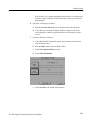
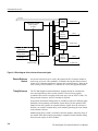
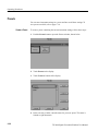
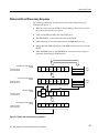
1
User Manual
TG 2000
Signal Generation Platform
070-9108-01
This document supports software version 2.0 and
above.
Copyright Tektronix, Inc. All rights reserved.
Tektronix products are covered by U.S. and foreign patents, issued and pending. Information in this publication supercedes
that in all previously published material. Specifications and price change privileges reserved.
Printed in the U.S.A.
Tektronix, Inc., P.O. Box 1000, Wilsonville, OR 97070–1000
TEKTRONIX and TEK are registered trademarks of Tektronix, Inc.
WARRANTY
Tektronix warrants that the products that it manufactures and sells will be free from defects in materials and workmanship
for a period of one (1) year from the date of shipment. If a product proves defective during this warranty period, Tektronix,
at its option, either will repair the defective product without charge for parts and labor, or will provide a replacement in
exchange for the defective product.
In order to obtain service under this warranty, Customer must notify Tektronix of the defect before the expiration of the
warranty period and make suitable arrangements for the performance of service. Customer shall be responsible for
packaging and shipping the defective product to the service center designated by Tektronix, with shipping charges prepaid.
Tektronix shall pay for the return of the product to Customer if the shipment is to a location within the country in which the
Tektronix service center is located. Customer shall be responsible for paying all shipping charges, duties, taxes, and any
other charges for products returned to any other locations.
This warranty shall not apply to any defect, failure or damage caused by improper use or improper or inadequate
maintenance and care. Tektronix shall not be obligated to furnish service under this warranty a) to repair damage resulting
from attempts by personnel other than Tektronix representatives to install, repair or service the product; b) to repair
damage resulting from improper use or connection to incompatible equipment; c) to repair any damage or malfunction
caused by the use of non-Tektronix supplies; or d) to service a product that has been modified or integrated with other
products when the effect of such modification or integration increases the time or difficulty of servicing the product.
THIS WARRANTY IS GIVEN BY TEKTRONIX IN LIEU OF ANY OTHER WARRANTIES, EXPRESS OR
IMPLIED. TEKTRONIX AND ITS VENDORS DISCLAIM ANY IMPLIED WARRANTIES OF
MERCHANTABILITY OR FITNESS FOR A PARTICULAR PURPOSE. TEKTRONIX’ RESPONSIBILITY TO
REPAIR OR REPLACE DEFECTIVE PRODUCTS IS THE SOLE AND EXCLUSIVE REMEDY PROVIDED TO
THE CUSTOMER FOR BREACH OF THIS WARRANTY. TEKTRONIX AND ITS VENDORS WILL NOT BE
LIABLE FOR ANY INDIRECT, SPECIAL, INCIDENTAL, OR CONSEQUENTIAL DAMAGES IRRESPECTIVE
OF WHETHER TEKTRONIX OR THE VENDOR HAS ADVANCE NOTICE OF THE POSSIBILITY OF SUCH
DAMAGES.
Service Assurance
If you have not already purchased Service Assurance for this product, you may do so at any time during the product’s
warranty period. Service Assurance provides Repair Protection and Calibration Services to meet your needs.
Repair Protection extends priority repair services beyond the product’s warranty period; you may purchase up to three
years of Repair Protection.
Calibration Services provide annual calibration of your product, standards compliance and required audit documentation,
recall assurance, and reminder notification of scheduled calibration. Coverage begins upon registration; you may purchase
up to five years of Calibration Services.
Service Assurance Advantages
Priced well below the cost of a single repair or calibration
Avoid delays for service by eliminating the need for separate purchase authorizations from your company
Eliminates unexpected service expenses
For Information and Ordering
For more information or to order Service Assurance, contact your Tektronix representative and provide the information
below. Service Assurance may not be available in locations outside the United States of America.
Name
Company
Address
City, State, Postal code
Country
Phone
VISA or Master Card number and expiration
date or purchase order number
Repair Protection (1,2, or 3 years)
Calibration Services (1,2,3,4, or 5 years)
Instrument model and serial number
Instrument purchase date
Table of Contents
General Safety Summary . . . . . . . . . . . . . . . . . . . . . . . . . . . . . . . . . . . .
Service Safety Summary . . . . . . . . . . . . . . . . . . . . . . . . . . . . . . . . . . . . .
Preface . . . . . . . . . . . . . . . . . . . . . . . . . . . . . . . . . . . . . . . . . . . . . . . . . . .
xi
xiii
xv
Getting Started . . . . . . . . . . . . . . . . . . . . . . . . . . . . . . . . . . . . . . . . . . . .
1–1
Product Description . . . . . . . . . . . . . . . . . . . . . . . . . . . . . . . . . . . . . . . . . . . . . . .
Accessories . . . . . . . . . . . . . . . . . . . . . . . . . . . . . . . . . . . . . . . . . . . . . . . . . . . . . .
BG1 Black Burst Generator Module . . . . . . . . . . . . . . . . . . . . . . . . . . . . . . .
SDP2000 Signal Development Program . . . . . . . . . . . . . . . . . . . . . . . . . . .
GPIB Card for SDP2000 Communications . . . . . . . . . . . . . . . . . . . . . . . . .
Accessory Kit . . . . . . . . . . . . . . . . . . . . . . . . . . . . . . . . . . . . . . . . . . . . . . . .
Configuration . . . . . . . . . . . . . . . . . . . . . . . . . . . . . . . . . . . . . . . . . . . . . . . . . . . .
Line Voltage Setting and Fuse Selection . . . . . . . . . . . . . . . . . . . . . . . . . . .
CPU Configuration Switch . . . . . . . . . . . . . . . . . . . . . . . . . . . . . . . . . . . . . .
Installation . . . . . . . . . . . . . . . . . . . . . . . . . . . . . . . . . . . . . . . . . . . . . . . . . . . . . .
Hardware Installation . . . . . . . . . . . . . . . . . . . . . . . . . . . . . . . . . . . . . . . . . .
Rackmount Installation . . . . . . . . . . . . . . . . . . . . . . . . . . . . . . . . . . . . . . . . .
Software Installation . . . . . . . . . . . . . . . . . . . . . . . . . . . . . . . . . . . . . . . . . . .
Power-On Procedure . . . . . . . . . . . . . . . . . . . . . . . . . . . . . . . . . . . . . . . . . . .
Incoming Inspection . . . . . . . . . . . . . . . . . . . . . . . . . . . . . . . . . . . . . . . . . . . . . . .
Equipment Needed . . . . . . . . . . . . . . . . . . . . . . . . . . . . . . . . . . . . . . . . . . . .
Incoming Inspection Procedure . . . . . . . . . . . . . . . . . . . . . . . . . . . . . . . . . .
1–1
1–2
1–2
1–2
1–3
1–3
1–3
1–3
1–5
1–6
1–6
1–6
1–8
1–9
1–10
1–10
1–10
Functional Overview . . . . . . . . . . . . . . . . . . . . . . . . . . . . . . . . . . . . . . . .
2–1
System Control . . . . . . . . . . . . . . . . . . . . . . . . . . . . . . . . . . . . . . . . . . . . . . .
Disk Drive . . . . . . . . . . . . . . . . . . . . . . . . . . . . . . . . . . . . . . . . . . . . . . . . . . .
Remote Control . . . . . . . . . . . . . . . . . . . . . . . . . . . . . . . . . . . . . . . . . . . . . . .
Generator Modules . . . . . . . . . . . . . . . . . . . . . . . . . . . . . . . . . . . . . . . . . . . .
Signal Memory . . . . . . . . . . . . . . . . . . . . . . . . . . . . . . . . . . . . . . . . . . . . . . .
Black Burst Module . . . . . . . . . . . . . . . . . . . . . . . . . . . . . . . . . . . . . . . . . . .
Battery Backup for NVRAM . . . . . . . . . . . . . . . . . . . . . . . . . . . . . . . . . . . .
Clocks and Frame Reset Signals . . . . . . . . . . . . . . . . . . . . . . . . . . . . . . . . . .
External Reference Genlock . . . . . . . . . . . . . . . . . . . . . . . . . . . . . . . . . . . . .
Timing References . . . . . . . . . . . . . . . . . . . . . . . . . . . . . . . . . . . . . . . . . . . .
Module Timing Delay . . . . . . . . . . . . . . . . . . . . . . . . . . . . . . . . . . . . . . . . . .
System Reference Delay with the AGL1 Module . . . . . . . . . . . . . . . . . . . .
Test Signals . . . . . . . . . . . . . . . . . . . . . . . . . . . . . . . . . . . . . . . . . . . . . . . . . .
Shared Module Memory . . . . . . . . . . . . . . . . . . . . . . . . . . . . . . . . . . . . . . . .
Front Panel Overview . . . . . . . . . . . . . . . . . . . . . . . . . . . . . . . . . . . . . . . . . . . . .
Brief Description of the Front Panel Controls . . . . . . . . . . . . . . . . . . . . . . .
Touch Screen and Front-Panel Controls . . . . . . . . . . . . . . . . . . . . . . . . . . . . . . .
2–1
2–1
2–1
2–2
2–2
2–3
2–3
2–3
2–4
2–4
2–5
2–6
2–7
2–8
2–9
2–9
2–10
Getting Started
Operating Basics
TG 2000 Signal Generation Platform User Manual
i
Table of Contents
Touch Screen Display . . . . . . . . . . . . . . . . . . . . . . . . . . . . . . . . . . . . . . . . . .
System Function Windows . . . . . . . . . . . . . . . . . . . . . . . . . . . . . . . . . . . . . .
Cursor Buttons and Knob . . . . . . . . . . . . . . . . . . . . . . . . . . . . . . . . . . . . . . .
Keypad . . . . . . . . . . . . . . . . . . . . . . . . . . . . . . . . . . . . . . . . . . . . . . . . . . . . .
2–10
2–12
2–16
2–18
Operating Procedures . . . . . . . . . . . . . . . . . . . . . . . . . . . . . . . . . . . . . . .
2–21
Allocating System Resources . . . . . . . . . . . . . . . . . . . . . . . . . . . . . . . . . . . . . . . .
Clock Allocation . . . . . . . . . . . . . . . . . . . . . . . . . . . . . . . . . . . . . . . . . . . . . .
Frame Reset Allocation . . . . . . . . . . . . . . . . . . . . . . . . . . . . . . . . . . . . . . . . .
Calibration . . . . . . . . . . . . . . . . . . . . . . . . . . . . . . . . . . . . . . . . . . . . . . . . . . . . . .
Date/Time Set . . . . . . . . . . . . . . . . . . . . . . . . . . . . . . . . . . . . . . . . . . . . . . . . . . . .
Front Panel Enable and Timeout . . . . . . . . . . . . . . . . . . . . . . . . . . . . . . . . . . . . .
Help . . . . . . . . . . . . . . . . . . . . . . . . . . . . . . . . . . . . . . . . . . . . . . . . . . . . . . . . . . .
Locked LED . . . . . . . . . . . . . . . . . . . . . . . . . . . . . . . . . . . . . . . . . . . . . . . . . . . . .
Module Status . . . . . . . . . . . . . . . . . . . . . . . . . . . . . . . . . . . . . . . . . . . . . . . . . . . .
Presets . . . . . . . . . . . . . . . . . . . . . . . . . . . . . . . . . . . . . . . . . . . . . . . . . . . . . . . . .
Create a Preset . . . . . . . . . . . . . . . . . . . . . . . . . . . . . . . . . . . . . . . . . . . . . . . .
Save Current Settings to an Existing Preset . . . . . . . . . . . . . . . . . . . . . . . . .
Recall, Rename, or Delete a Preset . . . . . . . . . . . . . . . . . . . . . . . . . . . . . . . .
References . . . . . . . . . . . . . . . . . . . . . . . . . . . . . . . . . . . . . . . . . . . . . . . . . . . . . .
Module Timing . . . . . . . . . . . . . . . . . . . . . . . . . . . . . . . . . . . . . . . . . . . . . . .
Select Reference . . . . . . . . . . . . . . . . . . . . . . . . . . . . . . . . . . . . . . . . . . . . . .
Reference Timing . . . . . . . . . . . . . . . . . . . . . . . . . . . . . . . . . . . . . . . . . . . . .
Selecting Internal or External Reference . . . . . . . . . . . . . . . . . . . . . . . . . . .
Renaming a Module . . . . . . . . . . . . . . . . . . . . . . . . . . . . . . . . . . . . . . . . . . . . . . .
Self Calibration . . . . . . . . . . . . . . . . . . . . . . . . . . . . . . . . . . . . . . . . . . . . . . . . . .
Sequences . . . . . . . . . . . . . . . . . . . . . . . . . . . . . . . . . . . . . . . . . . . . . . . . . . . . . . .
Add Sequence from Disk . . . . . . . . . . . . . . . . . . . . . . . . . . . . . . . . . . . . . . .
Run a Sequence . . . . . . . . . . . . . . . . . . . . . . . . . . . . . . . . . . . . . . . . . . . . . . .
Stop a Sequence . . . . . . . . . . . . . . . . . . . . . . . . . . . . . . . . . . . . . . . . . . . . . .
Screen Contrast . . . . . . . . . . . . . . . . . . . . . . . . . . . . . . . . . . . . . . . . . . . . . . . . . .
Selecting Test Signals . . . . . . . . . . . . . . . . . . . . . . . . . . . . . . . . . . . . . . . . . . . . .
Versions . . . . . . . . . . . . . . . . . . . . . . . . . . . . . . . . . . . . . . . . . . . . . . . . . . . . . . . .
2–21
2–21
2–22
2–23
2–23
2–24
2–25
2–26
2–27
2–28
2–28
2–29
2–29
2–30
2–30
2–32
2–33
2–33
2–34
2–35
2–36
2–36
2–37
2–37
2–38
2–38
2–39
Syntax . . . . . . . . . . . . . . . . . . . . . . . . . . . . . . . . . . . . . . . . . . . . . . . . . . . .
3–1
Programming Model . . . . . . . . . . . . . . . . . . . . . . . . . . . . . . . . . . . . . . . . . . . . . .
Addressing Module Test Signals . . . . . . . . . . . . . . . . . . . . . . . . . . . . . . . . .
Command Arguments . . . . . . . . . . . . . . . . . . . . . . . . . . . . . . . . . . . . . . . . . .
Argument Example . . . . . . . . . . . . . . . . . . . . . . . . . . . . . . . . . . . . . . . . . . . .
SCPI Commands and Queries . . . . . . . . . . . . . . . . . . . . . . . . . . . . . . . . . . . . . . .
Creating Commands . . . . . . . . . . . . . . . . . . . . . . . . . . . . . . . . . . . . . . . . . . .
Creating Queries . . . . . . . . . . . . . . . . . . . . . . . . . . . . . . . . . . . . . . . . . . . . . .
Parameter Types . . . . . . . . . . . . . . . . . . . . . . . . . . . . . . . . . . . . . . . . . . . . . .
Abbreviating Commands, Queries, and Parameters . . . . . . . . . . . . . . . . . . .
Chaining Commands and Queries . . . . . . . . . . . . . . . . . . . . . . . . . . . . . . . .
General Rules . . . . . . . . . . . . . . . . . . . . . . . . . . . . . . . . . . . . . . . . . . . . . . . .
IEEE 488.2 Common Commands . . . . . . . . . . . . . . . . . . . . . . . . . . . . . . . . . . . .
Command and Query Structure . . . . . . . . . . . . . . . . . . . . . . . . . . . . . . . . . .
Backus-Naur Form Definition . . . . . . . . . . . . . . . . . . . . . . . . . . . . . . . . . . .
Message Terminators . . . . . . . . . . . . . . . . . . . . . . . . . . . . . . . . . . . . . . . . . .
Constructed Mnemonics . . . . . . . . . . . . . . . . . . . . . . . . . . . . . . . . . . . . . . . . . . . .
Block Arguments . . . . . . . . . . . . . . . . . . . . . . . . . . . . . . . . . . . . . . . . . . . . . . . . .
3–1
3–1
3–1
3–2
3–4
3–4
3–4
3–5
3–6
3–6
3–7
3–9
3–9
3–9
3–9
3–10
3–10
Syntax
ii
TG 2000 Signal Generation Platform User Manual
Table of Contents
Special Characters . . . . . . . . . . . . . . . . . . . . . . . . . . . . . . . . . . . . . . . . . . . . . . . .
3–11
Sequence Programming . . . . . . . . . . . . . . . . . . . . . . . . . . . . . . . . . . . . .
3–13
Writing a Sequence Program . . . . . . . . . . . . . . . . . . . . . . . . . . . . . . . . . . . . . . . .
Sample Program 1 . . . . . . . . . . . . . . . . . . . . . . . . . . . . . . . . . . . . . . . . . . . . . . . .
Sample Program 2 . . . . . . . . . . . . . . . . . . . . . . . . . . . . . . . . . . . . . . . . . . . . . . . .
Sample Program 3 . . . . . . . . . . . . . . . . . . . . . . . . . . . . . . . . . . . . . . . . . . . . . . . .
Next Module . . . . . . . . . . . . . . . . . . . . . . . . . . . . . . . . . . . . . . . . . . . . . . . . .
Next Signal Set . . . . . . . . . . . . . . . . . . . . . . . . . . . . . . . . . . . . . . . . . . . . . . .
Next Signal . . . . . . . . . . . . . . . . . . . . . . . . . . . . . . . . . . . . . . . . . . . . . . . . . .
Previous Signal . . . . . . . . . . . . . . . . . . . . . . . . . . . . . . . . . . . . . . . . . . . . . . .
Internal Sync . . . . . . . . . . . . . . . . . . . . . . . . . . . . . . . . . . . . . . . . . . . . . . . . .
External Sync . . . . . . . . . . . . . . . . . . . . . . . . . . . . . . . . . . . . . . . . . . . . . . . .
Stop Sequence . . . . . . . . . . . . . . . . . . . . . . . . . . . . . . . . . . . . . . . . . . . . . . . .
Reset Sequence . . . . . . . . . . . . . . . . . . . . . . . . . . . . . . . . . . . . . . . . . . . . . . .
Running a Sequence . . . . . . . . . . . . . . . . . . . . . . . . . . . . . . . . . . . . . . . . . . . . . . .
Autostart Files . . . . . . . . . . . . . . . . . . . . . . . . . . . . . . . . . . . . . . . . . . . . . . . . . . .
Tcl Programming Changes . . . . . . . . . . . . . . . . . . . . . . . . . . . . . . . . . . . . . . . . . .
3–13
3–14
3–16
3–18
3–18
3–18
3–18
3–18
3–18
3–18
3–18
3–18
3–25
3–25
3–26
Functional Command Groups . . . . . . . . . . . . . . . . . . . . . . . . . . . . . . . .
3–27
* Common . . . . . . . . . . . . . . . . . . . . . . . . . . . . . . . . . . . . . . . . . . . . . . . . . . . . . .
Calibration . . . . . . . . . . . . . . . . . . . . . . . . . . . . . . . . . . . . . . . . . . . . . . . . . . . . . .
Display . . . . . . . . . . . . . . . . . . . . . . . . . . . . . . . . . . . . . . . . . . . . . . . . . . . . . . . . .
Instrument . . . . . . . . . . . . . . . . . . . . . . . . . . . . . . . . . . . . . . . . . . . . . . . . . . . . . .
MMemory . . . . . . . . . . . . . . . . . . . . . . . . . . . . . . . . . . . . . . . . . . . . . . . . . . . . . .
Program . . . . . . . . . . . . . . . . . . . . . . . . . . . . . . . . . . . . . . . . . . . . . . . . . . . . . . . .
Sense . . . . . . . . . . . . . . . . . . . . . . . . . . . . . . . . . . . . . . . . . . . . . . . . . . . . . . . . . .
Status . . . . . . . . . . . . . . . . . . . . . . . . . . . . . . . . . . . . . . . . . . . . . . . . . . . . . . . . . .
System . . . . . . . . . . . . . . . . . . . . . . . . . . . . . . . . . . . . . . . . . . . . . . . . . . . . . . . . .
3–28
3–28
3–29
3–29
3–30
3–31
3–31
3–32
3–33
Common Commands . . . . . . . . . . . . . . . . . . . . . . . . . . . . . . . . . . . . . . . .
3–35
Command Tree . . . . . . . . . . . . . . . . . . . . . . . . . . . . . . . . . . . . . . . . . . . . . . . . . . .
*CLS . . . . . . . . . . . . . . . . . . . . . . . . . . . . . . . . . . . . . . . . . . . . . . . . . . . . . . . . . .
*ESE(?) . . . . . . . . . . . . . . . . . . . . . . . . . . . . . . . . . . . . . . . . . . . . . . . . . . . . . . . .
*ESR? . . . . . . . . . . . . . . . . . . . . . . . . . . . . . . . . . . . . . . . . . . . . . . . . . . . . . . . . . .
*IDN? . . . . . . . . . . . . . . . . . . . . . . . . . . . . . . . . . . . . . . . . . . . . . . . . . . . . . . . . . .
*OPC(?) . . . . . . . . . . . . . . . . . . . . . . . . . . . . . . . . . . . . . . . . . . . . . . . . . . . . . . . .
*OPT? . . . . . . . . . . . . . . . . . . . . . . . . . . . . . . . . . . . . . . . . . . . . . . . . . . . . . . . . .
*RST . . . . . . . . . . . . . . . . . . . . . . . . . . . . . . . . . . . . . . . . . . . . . . . . . . . . . . . . . .
*SRE(?) . . . . . . . . . . . . . . . . . . . . . . . . . . . . . . . . . . . . . . . . . . . . . . . . . . . . . . . .
*STB? . . . . . . . . . . . . . . . . . . . . . . . . . . . . . . . . . . . . . . . . . . . . . . . . . . . . . . . . . .
*TST? . . . . . . . . . . . . . . . . . . . . . . . . . . . . . . . . . . . . . . . . . . . . . . . . . . . . . . . . . .
*WAI . . . . . . . . . . . . . . . . . . . . . . . . . . . . . . . . . . . . . . . . . . . . . . . . . . . . . . . . . .
3–35
3–36
3–37
3–38
3–39
3–40
3–41
3–42
3–43
3–44
3–45
3–46
:CALibration Commands . . . . . . . . . . . . . . . . . . . . . . . . . . . . . . . . . . . .
3–47
Command Tree . . . . . . . . . . . . . . . . . . . . . . . . . . . . . . . . . . . . . . . . . . . . . . . . . . .
:CALibration:ALL . . . . . . . . . . . . . . . . . . . . . . . . . . . . . . . . . . . . . . . . . . . . . . . .
:CALibration:MODules . . . . . . . . . . . . . . . . . . . . . . . . . . . . . . . . . . . . . . . . . . . .
3–47
3–48
3–49
:DISPlay Commands . . . . . . . . . . . . . . . . . . . . . . . . . . . . . . . . . . . . . . . .
3–51
Command Tree . . . . . . . . . . . . . . . . . . . . . . . . . . . . . . . . . . . . . . . . . . . . . . . . . . .
:DISPlay:CONTrast(?) . . . . . . . . . . . . . . . . . . . . . . . . . . . . . . . . . . . . . . . . . . . . .
:DISPlay:ERRor[:STATe](?) . . . . . . . . . . . . . . . . . . . . . . . . . . . . . . . . . . . . . . . .
:DISPlay[:WINDow]:TEXT[:DATA](?) . . . . . . . . . . . . . . . . . . . . . . . . . . . . . . .
:DISPlay[:WINDow][:STATe](?) . . . . . . . . . . . . . . . . . . . . . . . . . . . . . . . . . . . .
3–51
3–52
3–53
3–54
3–55
:INSTrument Commands . . . . . . . . . . . . . . . . . . . . . . . . . . . . . . . . . . . .
3–57
TG 2000 Signal Generation Platform User Manual
iii
Table of Contents
iv
Command Tree . . . . . . . . . . . . . . . . . . . . . . . . . . . . . . . . . . . . . . . . . . . . . . . . . . .
:INSTrument:CATalog? . . . . . . . . . . . . . . . . . . . . . . . . . . . . . . . . . . . . . . . . . . . .
:INSTrument:CATalog:FULL? . . . . . . . . . . . . . . . . . . . . . . . . . . . . . . . . . . . . . .
:INSTrument:DEFine(?) . . . . . . . . . . . . . . . . . . . . . . . . . . . . . . . . . . . . . . . . . . .
:INSTrument:DELete[:NAME] . . . . . . . . . . . . . . . . . . . . . . . . . . . . . . . . . . . . . .
:INSTrument:DELete:ALL . . . . . . . . . . . . . . . . . . . . . . . . . . . . . . . . . . . . . . . . .
:INSTrument[:SELect](?) . . . . . . . . . . . . . . . . . . . . . . . . . . . . . . . . . . . . . . . . . .
:INSTrument:NSELect(?) . . . . . . . . . . . . . . . . . . . . . . . . . . . . . . . . . . . . . . . . . .
3–57
3–58
3–59
3–60
3–61
3–62
3–63
3–64
:MMEMory Commands . . . . . . . . . . . . . . . . . . . . . . . . . . . . . . . . . . . . .
3–65
Drive Nomenclature . . . . . . . . . . . . . . . . . . . . . . . . . . . . . . . . . . . . . . . . . . . . . . .
MMEMory Command Arguments . . . . . . . . . . . . . . . . . . . . . . . . . . . . . . . . . . . .
Command Tree . . . . . . . . . . . . . . . . . . . . . . . . . . . . . . . . . . . . . . . . . . . . . . . . . . .
:MMEMory:CATalog? . . . . . . . . . . . . . . . . . . . . . . . . . . . . . . . . . . . . . . . . . . . . .
:MMEMory:CDIRectory(?) . . . . . . . . . . . . . . . . . . . . . . . . . . . . . . . . . . . . . . . . .
:MMEMory:COPY . . . . . . . . . . . . . . . . . . . . . . . . . . . . . . . . . . . . . . . . . . . . . . .
:MMEMory:DELete . . . . . . . . . . . . . . . . . . . . . . . . . . . . . . . . . . . . . . . . . . . . . . .
:MMEMory:INITialize . . . . . . . . . . . . . . . . . . . . . . . . . . . . . . . . . . . . . . . . . . . . .
:MMEMory:LOAD:DOWNload . . . . . . . . . . . . . . . . . . . . . . . . . . . . . . . . . . . . .
:MMEMory:LOAD:PRESet . . . . . . . . . . . . . . . . . . . . . . . . . . . . . . . . . . . . . . . .
:MMEMory:LOAD:SIGNal . . . . . . . . . . . . . . . . . . . . . . . . . . . . . . . . . . . . . . . . .
:MMEMory:MDIRectory . . . . . . . . . . . . . . . . . . . . . . . . . . . . . . . . . . . . . . . . . . .
:MMEMory:RDIRectory . . . . . . . . . . . . . . . . . . . . . . . . . . . . . . . . . . . . . . . . . . .
:MMEMory:SIGNal:ACTive? . . . . . . . . . . . . . . . . . . . . . . . . . . . . . . . . . . . . . . .
:MMEMory:SIGNal:ACTive:Catalog? . . . . . . . . . . . . . . . . . . . . . . . . . . . . . . . .
:MMEMory:SIGNal:ACTive:RESet . . . . . . . . . . . . . . . . . . . . . . . . . . . . . . . . . .
:MMEMory:SIGNal:ACTive:STATus? . . . . . . . . . . . . . . . . . . . . . . . . . . . . . . . .
:MMEMory:SIGNal:CATalog? . . . . . . . . . . . . . . . . . . . . . . . . . . . . . . . . . . . . . .
:MMEMory:SIGNal:CATalog:ALL? . . . . . . . . . . . . . . . . . . . . . . . . . . . . . . . . . .
:MMEMory:SIGNal:DELete . . . . . . . . . . . . . . . . . . . . . . . . . . . . . . . . . . . . . . . .
:MMEMory:SIGNal:DELete:ALL . . . . . . . . . . . . . . . . . . . . . . . . . . . . . . . . . . .
:MMEMory:SIGNal:STATus? . . . . . . . . . . . . . . . . . . . . . . . . . . . . . . . . . . . . . . .
:MMEMory:STORe:DOWNload . . . . . . . . . . . . . . . . . . . . . . . . . . . . . . . . . . . . .
:MMEMory:STORe:PRESet . . . . . . . . . . . . . . . . . . . . . . . . . . . . . . . . . . . . . . . .
:MMEMory:STORe:SIGNal . . . . . . . . . . . . . . . . . . . . . . . . . . . . . . . . . . . . . . . .
3–65
3–66
3–66
3–67
3–68
3–69
3–70
3–71
3–72
3–73
3–74
3–75
3–76
3–77
3–78
3–79
3–80
3–81
3–82
3–83
3–84
3–85
3–86
3–87
3–88
:PROGram Commands . . . . . . . . . . . . . . . . . . . . . . . . . . . . . . . . . . . . .
3–89
Command Tree . . . . . . . . . . . . . . . . . . . . . . . . . . . . . . . . . . . . . . . . . . . . . . . . . . .
:PROGram:CATalog? . . . . . . . . . . . . . . . . . . . . . . . . . . . . . . . . . . . . . . . . . . . . . .
:PROGram[:SELected]:DEFine(?) . . . . . . . . . . . . . . . . . . . . . . . . . . . . . . . . . . .
:PROGram[:SELected]:DELete[:SELEcted] . . . . . . . . . . . . . . . . . . . . . . . . . . . .
:PROGram[:SELected]:DELete:ALL . . . . . . . . . . . . . . . . . . . . . . . . . . . . . . . . .
:PROGram[:SELected]:NAME(?) . . . . . . . . . . . . . . . . . . . . . . . . . . . . . . . . . . . .
:PROGram[:SELected]:STATe(?) . . . . . . . . . . . . . . . . . . . . . . . . . . . . . . . . . . . .
:PROGram[:SELected]:WAIT(?) . . . . . . . . . . . . . . . . . . . . . . . . . . . . . . . . . . . . .
:PROGram:EXPLicit:DEFine(?) . . . . . . . . . . . . . . . . . . . . . . . . . . . . . . . . . . . . .
:PROGram:EXPLicit:DELete . . . . . . . . . . . . . . . . . . . . . . . . . . . . . . . . . . . . . . .
:PROGram:EXPLicit:STATe(?) . . . . . . . . . . . . . . . . . . . . . . . . . . . . . . . . . . . . . .
:PROGram:EXPLicit:WAIT(?) . . . . . . . . . . . . . . . . . . . . . . . . . . . . . . . . . . . . . .
3–89
3–90
3–91
3–92
3–93
3–94
3–95
3–96
3–97
3–98
3–99
3–100
:SENSe Queries . . . . . . . . . . . . . . . . . . . . . . . . . . . . . . . . . . . . . . . . . . . .
3–101
Command Tree . . . . . . . . . . . . . . . . . . . . . . . . . . . . . . . . . . . . . . . . . . . . . . . . . . .
:SENSe:ROSCillator:CLOCk3:CATalog? . . . . . . . . . . . . . . . . . . . . . . . . . . . . . .
:SENSe:ROSCillator:CLOCk:FREQuency? . . . . . . . . . . . . . . . . . . . . . . . . . . . .
:SENSe:ROSCillator:FRAMe2:CATalog? . . . . . . . . . . . . . . . . . . . . . . . . . . . . . .
3–101
3–102
3–103
3–104
TG 2000 Signal Generation Platform User Manual
Table of Contents
:SENSe:ROSCillator:FRAMe2:FREQuency? . . . . . . . . . . . . . . . . . . . . . . . . . . .
3–105
:STATus Commands . . . . . . . . . . . . . . . . . . . . . . . . . . . . . . . . . . . . . . . .
3–107
Command Tree . . . . . . . . . . . . . . . . . . . . . . . . . . . . . . . . . . . . . . . . . . . . . . . . . . .
[:EVENt]? . . . . . . . . . . . . . . . . . . . . . . . . . . . . . . . . . . . . . . . . . . . . . . . . . . . . . .
:CONDition? . . . . . . . . . . . . . . . . . . . . . . . . . . . . . . . . . . . . . . . . . . . . . . . . . . . .
:ENABle(?) . . . . . . . . . . . . . . . . . . . . . . . . . . . . . . . . . . . . . . . . . . . . . . . . . . . . .
:PTRansition(?) . . . . . . . . . . . . . . . . . . . . . . . . . . . . . . . . . . . . . . . . . . . . . . . . . .
:NTRansition(?) . . . . . . . . . . . . . . . . . . . . . . . . . . . . . . . . . . . . . . . . . . . . . . . . . .
:MAP(?) . . . . . . . . . . . . . . . . . . . . . . . . . . . . . . . . . . . . . . . . . . . . . . . . . . . . . . . .
:INSTrument(?) . . . . . . . . . . . . . . . . . . . . . . . . . . . . . . . . . . . . . . . . . . . . . . . . . .
:GCLOsure? . . . . . . . . . . . . . . . . . . . . . . . . . . . . . . . . . . . . . . . . . . . . . . . . . . . . .
3–108
3–110
3–111
3–112
3–113
3–114
3–115
3–116
3–117
:SYSTem Commands . . . . . . . . . . . . . . . . . . . . . . . . . . . . . . . . . . . . . . .
3–119
SYSTem Command Tree . . . . . . . . . . . . . . . . . . . . . . . . . . . . . . . . . . . . . . . . . . .
:SYSTem:DATE(?) . . . . . . . . . . . . . . . . . . . . . . . . . . . . . . . . . . . . . . . . . . . . . . .
:SYSTem:ERRor? . . . . . . . . . . . . . . . . . . . . . . . . . . . . . . . . . . . . . . . . . . . . . . . .
:SYSTem:HELP:SYNTax? . . . . . . . . . . . . . . . . . . . . . . . . . . . . . . . . . . . . . . . . .
:SYSTem:KLOCk:STATe(?) . . . . . . . . . . . . . . . . . . . . . . . . . . . . . . . . . . . . . . . .
:SYSTem:TIME(?) . . . . . . . . . . . . . . . . . . . . . . . . . . . . . . . . . . . . . . . . . . . . . . . .
:SYSTem:VERSion? . . . . . . . . . . . . . . . . . . . . . . . . . . . . . . . . . . . . . . . . . . . . . .
3–119
3–120
3–121
3–122
3–123
3–124
3–125
Status and Events
Status and Events . . . . . . . . . . . . . . . . . . . . . . . . . . . . . . . . . . . . . . . . . .
4–1
Registers . . . . . . . . . . . . . . . . . . . . . . . . . . . . . . . . . . . . . . . . . . . . . . . . . . . . . . . .
Status Registers . . . . . . . . . . . . . . . . . . . . . . . . . . . . . . . . . . . . . . . . . . . . . . . . . .
Enable Registers . . . . . . . . . . . . . . . . . . . . . . . . . . . . . . . . . . . . . . . . . . . . . . . . . .
Queues . . . . . . . . . . . . . . . . . . . . . . . . . . . . . . . . . . . . . . . . . . . . . . . . . . . . . . . . .
Status and Event Processing Sequence . . . . . . . . . . . . . . . . . . . . . . . . . . . . . . . .
Messages . . . . . . . . . . . . . . . . . . . . . . . . . . . . . . . . . . . . . . . . . . . . . . . . . . . . . . .
Synchronizing Execution . . . . . . . . . . . . . . . . . . . . . . . . . . . . . . . . . . . . . . . . . . .
4–1
4–1
4–4
4–6
4–7
4–8
4–8
Error Messages and Codes . . . . . . . . . . . . . . . . . . . . . . . . . . . . . . . . . . .
4–11
Command Errors . . . . . . . . . . . . . . . . . . . . . . . . . . . . . . . . . . . . . . . . . . . . . . . . .
Execution Errors . . . . . . . . . . . . . . . . . . . . . . . . . . . . . . . . . . . . . . . . . . . . . . . . .
Device Specific Errors . . . . . . . . . . . . . . . . . . . . . . . . . . . . . . . . . . . . . . . . . . . . .
Query Errors . . . . . . . . . . . . . . . . . . . . . . . . . . . . . . . . . . . . . . . . . . . . . . . . . . . . .
Device Errors . . . . . . . . . . . . . . . . . . . . . . . . . . . . . . . . . . . . . . . . . . . . . . . . . . . .
4–11
4–12
4–14
4–15
4–15
Appendix A: Specifications . . . . . . . . . . . . . . . . . . . . . . . . . . . . . . . . . . .
A–1
Appendix B: SCPI Conformance Information . . . . . . . . . . . . . . . . . . .
B–1
Appendix C: Disk Drive . . . . . . . . . . . . . . . . . . . . . . . . . . . . . . . . . . . . .
C–1
Specifications
TG 2000 Signal Generation Platform User Manual
v
Table of Contents
Supported File Types . . . . . . . . . . . . . . . . . . . . . . . . . . . . . . . . . . . . . . . . . .
Disk Drive Functions . . . . . . . . . . . . . . . . . . . . . . . . . . . . . . . . . . . . . . . . . .
Save Signals to Disk . . . . . . . . . . . . . . . . . . . . . . . . . . . . . . . . . . . . . . . . . . .
Replace Signals from Disk . . . . . . . . . . . . . . . . . . . . . . . . . . . . . . . . . . . . . .
Add Signals . . . . . . . . . . . . . . . . . . . . . . . . . . . . . . . . . . . . . . . . . . . . . . . . . .
Delete Signals . . . . . . . . . . . . . . . . . . . . . . . . . . . . . . . . . . . . . . . . . . . . . . . .
Preset File Utilities . . . . . . . . . . . . . . . . . . . . . . . . . . . . . . . . . . . . . . . . . . . .
Add Sequence from Disk . . . . . . . . . . . . . . . . . . . . . . . . . . . . . . . . . . . . . . .
C–1
C–2
C–2
C–4
C–6
C–9
C–10
C–13
Appendix D: Remote Interface . . . . . . . . . . . . . . . . . . . . . . . . . . . . . . .
D–1
Remote Control using the RS-232, Parallel, or GPIB Interface . . . . . . . . . . . . .
Remote Control using the Ground Closure Interface . . . . . . . . . . . . . . . . . . . . . .
Remote Downloading of Signal Files . . . . . . . . . . . . . . . . . . . . . . . . . . . . . . . . .
Remote Connectors . . . . . . . . . . . . . . . . . . . . . . . . . . . . . . . . . . . . . . . . . . . . . . .
GPIB Interface . . . . . . . . . . . . . . . . . . . . . . . . . . . . . . . . . . . . . . . . . . . . . . .
Parallel Interface . . . . . . . . . . . . . . . . . . . . . . . . . . . . . . . . . . . . . . . . . . . . . .
RS-232 Interface . . . . . . . . . . . . . . . . . . . . . . . . . . . . . . . . . . . . . . . . . . . . . .
Ground Closure Interface . . . . . . . . . . . . . . . . . . . . . . . . . . . . . . . . . . . . . . .
Remote Interface Setup . . . . . . . . . . . . . . . . . . . . . . . . . . . . . . . . . . . . . . . . . . . .
RS-232 Setup . . . . . . . . . . . . . . . . . . . . . . . . . . . . . . . . . . . . . . . . . . . . . . . .
Parallel Setup . . . . . . . . . . . . . . . . . . . . . . . . . . . . . . . . . . . . . . . . . . . . . . . .
GPIB Setup . . . . . . . . . . . . . . . . . . . . . . . . . . . . . . . . . . . . . . . . . . . . . . . . . .
Remote Port . . . . . . . . . . . . . . . . . . . . . . . . . . . . . . . . . . . . . . . . . . . . . . . . .
Gnd Closure . . . . . . . . . . . . . . . . . . . . . . . . . . . . . . . . . . . . . . . . . . . . . . . . .
Locking out Front-Panel Controls . . . . . . . . . . . . . . . . . . . . . . . . . . . . . . . .
D–1
D–2
D–3
D–4
D–4
D–4
D–5
D–5
D–7
D–7
D–8
D–9
D–9
D–10
D–10
Appendix E: Installation . . . . . . . . . . . . . . . . . . . . . . . . . . . . . . . . . . . . .
E–1
Preventing Component Damage . . . . . . . . . . . . . . . . . . . . . . . . . . . . . . . . . . . . .
Module Installation . . . . . . . . . . . . . . . . . . . . . . . . . . . . . . . . . . . . . . . . . . . . . . .
Hardware Installation . . . . . . . . . . . . . . . . . . . . . . . . . . . . . . . . . . . . . . . . . .
Signal Set Installation . . . . . . . . . . . . . . . . . . . . . . . . . . . . . . . . . . . . . . . . . .
Instrument Backup and Restore . . . . . . . . . . . . . . . . . . . . . . . . . . . . . . . . . . . . . .
Required Equipment . . . . . . . . . . . . . . . . . . . . . . . . . . . . . . . . . . . . . . . . . . .
Instrument Backup . . . . . . . . . . . . . . . . . . . . . . . . . . . . . . . . . . . . . . . . . . . .
Instrument Restore from Backup . . . . . . . . . . . . . . . . . . . . . . . . . . . . . . . . .
Module Removal . . . . . . . . . . . . . . . . . . . . . . . . . . . . . . . . . . . . . . . . . . . . . . . . .
E–1
E–2
E–2
E–6
E–8
E–8
E–8
E–9
E–9
Glossary and Index
vi
TG 2000 Signal Generation Platform User Manual
Table of Contents
List of Figures
Figure 1–1: Location of power connections and configuration . . . . . .
Figure 1–2: Location of the service diagnostics switch . . . . . . . . . . . .
Figure 1–3: Installing the rackmount hardware . . . . . . . . . . . . . . . . .
Figure 1–4: Placing the TG 2000 Signal Generation Platform
in the rack . . . . . . . . . . . . . . . . . . . . . . . . . . . . . . . . . . . . . . . . . . . . .
Figure 1–5: Hooking up the clock output to the frequency counter . .
Figure 2–1: TG 2000 Signal Generation Platform simplified
block diagram . . . . . . . . . . . . . . . . . . . . . . . . . . . . . . . . . . . . . . . . . .
Figure 2–2: Block diagram of the clocks and frame reset signals . . . .
Figure 2–3: Comparison of module delay and system delay
from a reference . . . . . . . . . . . . . . . . . . . . . . . . . . . . . . . . . . . . . . . .
Figure 2–4: Block diagram of module timing delay . . . . . . . . . . . . . . .
Figure 2–5: Block diagram of the AGL1 Generator module
reference timing delay . . . . . . . . . . . . . . . . . . . . . . . . . . . . . . . . . . .
Figure 2–6: Module and test signal hierarchy . . . . . . . . . . . . . . . . . . .
Figure 2–7: TG 2000 Signal Generation Platform front panel . . . . . .
Figure 2–8: Main display features . . . . . . . . . . . . . . . . . . . . . . . . . . . . .
Figure 2–9: Browsed and selected icons . . . . . . . . . . . . . . . . . . . . . . . .
Figure 2–10: Using the knob to open a list of signals . . . . . . . . . . . . . .
1–4
1–5
1–7
1–8
1–13
2–2
2–4
2–5
2–6
2–7
2–7
2–9
2–10
2–16
2–17
Figure 3–1: Example of SCPI subsystem hierarchy . . . . . . . . . . . . . . .
Figure 3–2: Example of abbreviating a command . . . . . . . . . . . . . . . .
Figure 3–3: Example of chaining commands and queries . . . . . . . . . .
Figure 3–4: Example of omitting root and lower-level nodes
in a chained message . . . . . . . . . . . . . . . . . . . . . . . . . . . . . . . . . . . . .
3–4
3–6
3–7
Figure 4–1: The status byte register (SBR) . . . . . . . . . . . . . . . . . . . . . .
Figure 4–2: The standard event status register (SESR) . . . . . . . . . . . .
Figure 4–3: The event status enable register (ESER) . . . . . . . . . . . . .
Figure 4–4: The service request enable register (SRER) . . . . . . . . . . .
Figure 4–5: Status and event processing sequence . . . . . . . . . . . . . . . .
4–2
4–3
4–5
4–5
4–7
Figure D–1: Rear panel remote connectors . . . . . . . . . . . . . . . . . . . . .
Figure D–2: RS-232 connector pin assignments . . . . . . . . . . . . . . . . . .
Figure D–3: Serial port ground closure functions . . . . . . . . . . . . . . . .
Figure D–4: Sample ground closure control panel . . . . . . . . . . . . . . . .
D–4
D–5
D–5
D–6
TG 2000 Signal Generation Platform User Manual
3–7
vii
Table of Contents
Figure E–1: Rear panel, showing slot numbering . . . . . . . . . . . . . . . .
Figure E–2: Top cover removal . . . . . . . . . . . . . . . . . . . . . . . . . . . . . . .
Figure E–3: Rear panel removal . . . . . . . . . . . . . . . . . . . . . . . . . . . . . .
Figure E–4: Module flange . . . . . . . . . . . . . . . . . . . . . . . . . . . . . . . . . . .
Figure E–5: Installing the module . . . . . . . . . . . . . . . . . . . . . . . . . . . . .
Figure E–6: Top screw . . . . . . . . . . . . . . . . . . . . . . . . . . . . . . . . . . . . . . .
viii
E–2
E–3
E–4
E–4
E–5
E–6
TG 2000 Signal Generation Platform User Manual
Table of Contents
List of Tables
Table 1–1: AC power fuse requirements . . . . . . . . . . . . . . . . . . . . . . .
1–4
Table 2–1: Keypad definitions . . . . . . . . . . . . . . . . . . . . . . . . . . . . . . . .
2–18
Table 3–1: Parameter types used in syntax descriptions . . . . . . . . . .
Table 3–2: * Common commands . . . . . . . . . . . . . . . . . . . . . . . . . . . .
Table 3–3: :CALibration commands . . . . . . . . . . . . . . . . . . . . . . . . . .
Table 3–4: :DISPlay commands . . . . . . . . . . . . . . . . . . . . . . . . . . . . . .
Table 3–5: :INSTrument commands . . . . . . . . . . . . . . . . . . . . . . . . . .
Table 3–6: :MMEMory commands . . . . . . . . . . . . . . . . . . . . . . . . . . .
Table 3–7: :PROGram commands . . . . . . . . . . . . . . . . . . . . . . . . . . . .
Table 3–8: :SENSe commands . . . . . . . . . . . . . . . . . . . . . . . . . . . . . . . .
Table 3–9: :STATus commands . . . . . . . . . . . . . . . . . . . . . . . . . . . . . .
Table 3–10: :SYSTem commands . . . . . . . . . . . . . . . . . . . . . . . . . . . . .
3–5
3–28
3–28
3–29
3–29
3–30
3–31
3–31
3–32
3–33
Table 4–1: SRB bit functions . . . . . . . . . . . . . . . . . . . . . . . . . . . . . . . . .
Table 4–2: SESR bit functions . . . . . . . . . . . . . . . . . . . . . . . . . . . . . . . .
Table 4–3: Command errors . . . . . . . . . . . . . . . . . . . . . . . . . . . . . . . . .
Table 4–4: Execution errors . . . . . . . . . . . . . . . . . . . . . . . . . . . . . . . . .
Table 4–5: Device specific errors . . . . . . . . . . . . . . . . . . . . . . . . . . . . .
Table 4–6: Query errors . . . . . . . . . . . . . . . . . . . . . . . . . . . . . . . . . . . .
Table 4–7: Device errors . . . . . . . . . . . . . . . . . . . . . . . . . . . . . . . . . . . .
4–2
4–3
4–11
4–12
4–14
4–15
4–15
Table A–1: AC power source . . . . . . . . . . . . . . . . . . . . . . . . . . . . . . . . .
Table A–2: Physical dimensions . . . . . . . . . . . . . . . . . . . . . . . . . . . . . .
Table A–3: Environmental characteristics . . . . . . . . . . . . . . . . . . . . . .
Table A–4: System clock and frame reset . . . . . . . . . . . . . . . . . . . . . .
Table A–5: Certifications and compliances . . . . . . . . . . . . . . . . . . . . .
A–1
A–1
A–2
A–2
A–3
Table B–1: SCPI conformance information
....................
B–1
Table E–1: Module slot assignments . . . . . . . . . . . . . . . . . . . . . . . . . . .
E–2
TG 2000 Signal Generation Platform User Manual
ix
Table of Contents
x
TG 2000 Signal Generation Platform User Manual
General Safety Summary
Review the following safety precautions to avoid injury and prevent damage to
this product or any products connected to it.
Only qualified personnel should perform service procedures.
To avoid potential hazards, use this product only as specified.
Injury Precautions
Use Proper Power Cord. To avoid fire hazard, use only the power cord specified
for this product.
Avoid Electric Overload. To avoid electric shock or fire hazard, do not apply a
voltage to a terminal that is outside the range specified for that terminal.
Ground the Product. This product is grounded through the grounding conductor
of the power cord. To avoid electric shock, the grounding conductor must be
connected to earth ground. Before making connections to the input or output
terminals of the product, ensure that the product is properly grounded.
Do Not Operate Without Covers. To avoid electric shock or fire hazard, do not
operate this product with covers or panels removed.
Use Proper Fuse. To avoid fire hazard, use only the fuse type and rating specified
for this product.
Do Not Operate in Wet/Damp Conditions. To avoid electric shock, do not operate
this product in wet or damp conditions.
Do Not Operate in an Explosive Atmosphere. To avoid injury or fire hazard, do not
operate this product in an explosive atmosphere.
Product Damage
Precautions
Use Proper Power Source. Do not operate this product from a power source that
applies more than the voltage specified.
Use Proper Voltage Setting. Before applying power, ensure that the line selector is
in the proper position for the power source being used.
Provide Proper Ventilation. To prevent product overheating, provide proper
ventilation.
Do Not Operate With Suspected Failures. If you suspect there is damage to this
product, have it inspected by qualified service personnel.
TG 2000 Television Generation Platform User Manual
xi
General Safety Summary
Symbols and Terms
Terms in this Manual. These terms may appear in this manual:
WARNING. Warning statements identify conditions or practices that could result
in injury or loss of life.
CAUTION. Caution statements identify conditions or practices that could result in
damage to this product or other property.
Terms on the Product. These terms may appear on the product:
DANGER indicates an injury hazard immediately accessible as you read the
marking.
WARNING indicates an injury hazard not immediately accessible as you read the
marking.
CAUTION indicates a hazard to property including the product.
Symbols on the Product. The following symbols may appear on the product:
DANGER
High Voltage
Certifications and
Compliances
xii
Protective Ground
(Earth) Terminal
ATTENTION
Refer to Manual
Double
Insulated
Refer to the specifications section for a listing of certifications and compliances
that apply to this product.
TG 2000 Television Generation Platform User Manual
Service Safety Summary
Only qualified personnel should perform service procedures. Read this Service
Safety Summary and the General Safety Summary before performing any service
procedures.
Do Not Service Alone. Do not perform internal service or adjustments of this
product unless another person capable of rendering first aid and resuscitation is
present.
Disconnect Power. To avoid electric shock, disconnect the main power by means
of the power cord or, if provided, the power switch.
Use Care When Servicing With Power On. Dangerous voltages or currents may
exist in this product. Disconnect power and disconnect test leads before
removing protective panels, soldering, or replacing components.
To avoid electric shock, do not touch exposed connections.
TG 2000 Television Generation Platform User Manual
xiii
Service Safety Summary
xiv
TG 2000 Television Generation Platform User Manual
Preface
This manual describes features and specifications that apply to the platform.
These include system configuration and the common control interface. Features
that are specific to a module are described in the user manual for that module.
This manual is designed with space at the rear for the user manuals that
accompany your generator and special function modules. In addition, this
manual includes a disk holder to store the signal set disks packaged with many
of the generator module user manuals.
About This Manual
This manual is composed of the following sections:
Getting Started shows you how to configure and install your platform,
provides an incoming inspection procedure, and describes the mainframe
options.
Operating Basics describes front panel operation of the mainframe and
modules and shows how to use the front panel and touch screen controls.
Syntax and Commands defines the syntax used in command descriptions,
presents a list of all command subsystems, as well as detailed descriptions of
all programming commands.
Status and Events describes how the status and Events Reporting system
operates and presents a list of all system errors.
Appendices provide specifications and information about the remote
interface, the disk drive, and the mainframe installation.
Related Manuals
The following documents are also available for the platform:
The TG 2000 Signal Generation Platform User Manual describes how to use
the TG 2000 Platform. It also contains information about SCPI commands,
programming structure, and status and events for the platform. Some of this
information applies to all generator modules, including the DVG1 Generator
module. This manual is a standard accessary to the TG 2000 Platform
mainframe.
TG 2000 Signal Generation Platform User Manual
xv
Preface
The TG 2000 Signal Generation Platform Service Manual describes how to
service the mainframe to the module level and provides general information
about servicing generator modules. This optional manual must be ordered
separately.
A module user manual is included with each optional module. Contact your
Tektronix representative for a list of generator and special function modules.
Contacting Tektronix
Product
Support
For application-oriented questions about a Tektronix measurement product, call toll free in North America:
1-800-TEK-WIDE (1-800-835-9433 ext. 2400)
6:00 a.m. – 5:00 p.m. Pacific time
Or, contact us by e-mail:
[email protected]
For product support outside of North America, contact your
local Tektronix distributor or sales office.
Service
Support
Contact your local Tektronix distributor or sales office. Or, visit
our web site for a listing of worldwide service locations.
http://www.tek.com
xvi
For other
information
In North America:
1-800-TEK-WIDE (1-800-835-9433)
An operator will direct your call.
To write us
Tektronix, Inc.
P.O. Box 1000
Wilsonville, OR 97070-1000
TG 2000 Signal Generation Platform User Manual
Getting Started
This section contains the following:
Product description
Accessories list
Configuration instructions
Installation instructions
Incoming inspection
Product Description
The TG 2000 Signal Generation Platform provides multiformat, precision
television test signals for both analog and digital video standards. The physical
configuration is a mainframe with up to nine plug-in modules. Modules either
generate signals or provide special functions, such as genlock capability.
You can use included software (SDP2000 Signal Development Program) to
generate custom test signals, which you can store on a disk or transfer directly
into the memory of a generator module.
The TG 2000 Signal Generation Platform addresses the needs of research and
development, engineering, manufacturing test, and most operational environments.
These are some of the key features of the platform:
Modular architecture with up to nine generator or special function modules
Support of analog and digital environments for most component and
composite video signal formats
Reference generator performance level
Modules genlocked to external reference with the optional AGL1 Genlock
module
Included Microsoft Windows-based SDP2000 software to create new signals
Remote control, using the RS-232, ground closure, parallel, or optional
GPIB interface with the SCPI command set
Full support of VM700A video measurement routines
TG 2000 Signal Generation Platform User Manual
1–1
Getting Started
Variable transmission parameters, such as jitter amplitude and frequency, for
serial digital formats using the DVG1 Generator module with option S1
Variable signal parameters for some analog and digital format modules
Circle and text overlays on test signals for some modules
Simultaneous 525/60 and 625/50 signal generation
Moving signals for compression system testing
Programmable system clocks to support standard and custom formats
Flash EPROM allows easy upgrades to system software
Accessories
This section describes the key accessories for the TG 2000 Signal Generation
Platform. For a complete list of accessories and their Tektronix part numbers,
refer to the Replaceable Mechanical Parts list at the back of this manual.
In addition to the options described in this manual, Tektronix offers maintenance
options that cover adjustment and repair services. Contact your Tektronix
representative for details.
BG1 Black Burst
Generator Module
The BG1 Generator module is supplied as a standard accessory. There are six
black burst signals to select from; the module provides the selected black burst
signal on the three rear-panel connectors. Additionally, the module can provide
one of the system clocks from its rear-panel clock output.
More than one BG1 Generator module can be added to the mainframe to provide
enough flexibility to meet virtually any system timing requirement. The BG1
Generator module can be removed without affecting system operation.
SDP2000 Signal
Development Program
The SDP2000 Signal Development Program is supplied as a standard accessory.
This program runs under Microsoft Windows 3.1 or higher. All features except
the parallel port are compatible with Windows NT. All features are compatible
with Windows 95. For general information about the SDP2000 program, refer to
either the SDP2000 program online help or the SDP2000 Signal Development
Program User Manual.
Using this program, you can create custom signals for the platform, and
download the signals through disk or remote interface. Refer to the SDP2000
program online help for instructions on remote downloading of signals.
1–2
TG 2000 Signal Generation Platform User Manual
Getting Started
GPIB Card for SDP2000
Communications
The Tektronix S3FG210 is a GPIB-PCII/IIA interface card that you can purchase
from Tektronix. It provides the type of interface needed to operate the TG 2000
Signal Generation Platform when performing GPIB communications with the
SDP2000/TGCOMM software.
Accessory Kit
This kit is shipped as a standard accessory. It includes a Torx T-10 bit (needed to
secure the modules), two fuses, and a blank panel (to fill the gap when a module
is removed). The fuses support the two line voltage settings; see Line Voltage
Setting and Fuse Selection for instructions.
Configuration
The TG 2000 Signal Generation Platform mainframe requires configuration for
the installation of new modules and for the AC line voltage. The TG 2000 Signal
Generation Platform mainframe is configured at the factory to support the
optional module generators that you order. Modules ordered separately should be
installed by a qualified service technician. Refer to Installation in this section
and to the Installation discussion in your module user manual for instructions on
adding a generator module.
Line Voltage Setting and
Fuse Selection
The TG 2000 Signal Generation Platform mainframe must be configured to
operate on your local AC power system. Always unplug the TG 2000 Signal
Generation Platform before changing the line voltage setting or the fuse.
WARNING. To avoid electrical shock, be sure that the power cord is disconnected
before checking the fuse or changing the line voltage selector.
CAUTION. To avoid damaging the TG 2000 Signal Generation Platform, always
use the correct fuse for the line voltage. The 230 V setting requires a 3 AT fuse
for proper protection. See the fuse chart located on the rear panel near the line
voltage selector for the proper fuse for each line voltage setting.
Figure 1–1 shows the location on the rear panel of line power connector, line
selector, fuse and power switch, as well as how to change the line voltage
setting. Table 1–1 lists the proper fuse for each line voltage setting.
TG 2000 Signal Generation Platform User Manual
1–3
Getting Started
Table 1–1: AC power fuse requirements
Line Voltage Setting
Fuse Rating
115 V
Slow blow, 6 AT
230 V
Slow blow, 3 AT
Line
selector
Fuse
Power
switch
AC Line
connecter
Figure 1–1: Location of power connections and configuration
1–4
TG 2000 Signal Generation Platform User Manual
Getting Started
CPU Configuration Switch
The rotary switch shown in Figure 1–2 is for use by service technicians only.
The switch must be in position “0” for normal operation.
Figure 1–2: Location of the service diagnostics switch
TG 2000 Signal Generation Platform User Manual
1–5
Getting Started
Installation
This section describes the hardware and software installation requirements for
the TG 2000 Signal Generation Platform mainframe. General instructions for
installing modules begin on page E–2 of this manual. For installation information that is unique to a particular module, refer to the module user manual.
Hardware Installation
The TG 2000 Signal Generation Platform is shipped with the optional generator
modules that you ordered configured and installed. Only qualified service
technicians should install modules in the TG 2000 Signal Generation Platform
mainframe. Technicians can refer to Appendix E of this manual for general
instructions. Each type of module has specific installation requirements, which
are discussed in the module user manual. Refer to Rackmount Installation on
page 1–6 for rackmounting instructions.
To properly install and power on the TG 2000 Signal Generation Platform,
follow these steps:
1. Check that you have the appropriate operating environment. Check
Appendix A for temperature, humidity, altitude, and other environmental
requirements.
2. Leave space for cooling by ensuring standard side clearance for rack
mounting or 2 inches (5.1 cm) of side clearance for counter top use. Also,
ensure sufficient rear clearance (approximately 2 inches) so that cables are
not damaged by sharp bends.
3. Check that the power connection is properly configured. Refer to Configuration on page 1–3 for instructions.
4. Connect the power cord from the rear panel power connector to the power
system.
Rackmount Installation
The TG 2000 Signal Generation Platform mainframe is configured at shipment
for use in an equipment rack.
To install the mainframe into the rack, follow these steps:
1. Use the information in Figure 1–3 to connect the rackmount hardware to the
rack.
2. Referring to Figure 1–4, support the mainframe while inserting its attached
rack pieces into the pieces attached to the rack.
3. Slide the mainframe completely into the rack, continuing to support the
mainframe until the stop latches click into place on both sides. The
installation is not secure until this latching occurs.
1–6
TG 2000 Signal Generation Platform User Manual
Getting Started
Automatic latches
Rear mounting
bracket
Chassis section
Automatic latches
Flat bar nut
Stationary section
Intermediate
section
Stop latch
hole
Rear rack
10–32 Phs screws
Flat bar nut
Front rack
Flat bar nut
(Use if front rail
is not tapped)
10–32 Phs screws
Figure 1–3: Installing the rackmount hardware
TG 2000 Signal Generation Platform User Manual
1–7
Getting Started
Side-out track
Stop latch
Figure 1–4: Placing the TG 2000 Signal Generation Platform in the rack
To remove the TG 2000 Signal Generation Platform mainframe from the rack,
follow these steps:
1. Slide the mainframe out until it stops at the catches.
2. Support the mainframe while you press in on the stop latch buttons on each
side. This action will free the TG 2000 Signal Generation Platform to slide
completely out of the rack.
3. Provide support while you slide the mainframe out of the rack.
Software Installation
1–8
There are three types of software you can install:
The SDP2000 Signal Development Program (use the disks and instructions
included in the SDP2000 User manual, standard accessory).
Signal sets for each module type (use disks and instructions included in the
module user manual). If you purchased your modules installed in a mainframe, signal sets are already installed for you.
Module or mainframe firmware. In certain instances, a firmware upgrade kit
may be issued, including disks and instructions. You will not usually install
instrument firmware; it is already installed in your mainframe and modules.
TG 2000 Signal Generation Platform User Manual
Getting Started
Power-On Procedure
This section describes how to check that your TG 2000 Signal Generation
Platform powers on properly. Be certain that the platform is properly configured
and installed before applying power. Refer to Configuration on page 1–3 and
Installation on page 1–6.
1. Make sure that the top and rear-panel covers are on the mainframe.
2. Connect the mainframe to the appropriate mains power and turn on the
rear-panel power switch.
3. Set the rear-panel power switch on.
4. Push the front-panel On/Standby switch to apply power to your platform.
The mainframe and each of its modules perform a self test to verify
functionality. The self test requires a minute or less to complete, depending
on the number of modules installed.
5. After the self-tests are successfully completed, check that the front panel
display is working, and that there are no displayed errors.
The platform recalls the settings that were active when powered off.
Power-on settings are stored in nonvolatile memory.
NOTE. If your TG 2000 Signal Generation Platform powers on, but a module
fails to appear in the Modules window, the module may require service. Refer to
the appropriate service manual for assistance (service manuals for the mainframe and modules are optional accessories).
6. If this is the first time you have powered on the platform after shipment or
long storage, leave the front-panel On/Standby power switch on for eight
hours to fully charge the system batteries. The batteries maintain system data
when mains power is disconnected.
NOTE. If backup power is lost, the NVRAM is erased. You must reload the
generator test signals from the supplied disks, from backup disks you previously
created, or through a remote port (from the SDP2000 Signal Development
Program). You should also run self cal on all modules to reestablish peak
performance.
TG 2000 Signal Generation Platform User Manual
1–9
Getting Started
Incoming Inspection
The incoming inspection procedure verifies that the TG 2000 Signal Generation
Platform mainframe is operating correctly after shipment. After using this
procedure to check the mainframe, use the incoming inspection procedures in
you module user manuals to verify the operation of your modules. To verify the
performance specifications, refer to the Performance Verification Procedure in
the TG 2000 Signal Generation Platform Service Manual.
Equipment Needed
Incoming Inspection
Procedure
You will need the following equipment to perform this procedure.
BG1 Black Burst Generator module to verify the internal clock.
Frequency counter to verify the clock output from the BG1 Generator
module. The frequency counter input should be capable of 75 W impedance,
AC coupling and 0.4 V p-p amplitude.
BNC cable to connect the BG1 Generator module to the frequency counter.
3 1/2 inch, high-density, DOS formatted disk to check the disk drive.
Perform the following steps to check for correct instrument operation:
1. Install the mainframe as described under Installation on page 1–6.
2. Power on the mainframe as described in the Power On Procedure on
page 1–9.
3. If the display is working and no errors appear on the display, then the
mainframe passed its self tests. To determine if the modules passed their
tests, press the Status key and check that no module has a “Failed power up”
status. Refer to the module User manual for further checks on each module.
4. Wait 20 minutes for the TG 2000 Signal Generation Platform and its
generator modules to warm up.
5. Run the module self calibration as follows:
a. Press the Utilities key.
b. Touch Module Self Cal on screen.
c. Touch CLOCK:1 Self Cal on screen. You might want to select any new
modules at this time. Refer to the Incoming Inspection Procedure in the
module user manuals to see if they require self cal.
d. Touch Start Self Cal on screen.
1–10
TG 2000 Signal Generation Platform User Manual
Getting Started
Self cal takes 2 to 5 minutes depending on the module. An error message
indicates a failed calibration. If the self cal fails, contact your Tektronix
Representative.
6. Check the LCD display as follows:
a. Push the Screen Contrast button on the right side of the front panel.
b. Check that you can adjust the display contrast using the knob. If you
cannot adjust the contrast, the front panel has an error and may require
service.
7. Check the disk drive as follows:
a. Check that the disk is formatted and not write protected, and insert the
disk into the disk drive.
b. Push the Disk button to enter the Disk window.
c. Touch Save Signals to Disk on screen.
d. Touch Select Destination.
e. Touch New Dir at the bottom of the window.
TG 2000 Signal Generation Platform User Manual
1–11
Getting Started
f.
Create a directory named “TEST” (as shown below) by pressing the keys
t e s t.
g. Press OK to make the directory and return to the Save Signals to Disk
window.
h. Check that the new directory “TEST” appears in the second column
under Directories. If the directory does not appear, check the disk or try
a new formatted disk and try again to create the directory. A continued
failure may indicate a defective disk drive.
8. Connect the Clock output from the BG1 Generator module to the frequency
counter as shown in Figure 1–5.
1–12
TG 2000 Signal Generation Platform User Manual
Getting Started
TG 2000 platform
(rear panel)
BG1
Frequency
counter
Clock output
Figure 1–5: Hooking up the clock output to the frequency counter
9. Set the frequency counter for AC coupling, 400 mV amplitude, and the
100 MHz range.
10. Set the clock frequency to 27 MHz as follows:
a. Push the Modules button.
b. Touch BG1 on screen.
c. Touch NTSC on screen.
d. Touch Black Burst on screen.
e. Touch Module Parameters on screen.
f.
Touch Clock Out on screen. Note the current frequency setting.
g. Using the keypad, press the keys “2 7 M/u Enter” to set Out Freq: to
27.0 MHz. If the selector Output at the bottom of the window indicates
Disabled, touch it once to enable the Clock output on the BG1 module.
11. Check that the frequency counter measures 27 MHz within 1 ppm or the
accuracy of your counter. A continued failure indicates a problem with the
clock circuit; contact your Tektronix Representative.
12. Restore the clock frequency noted in step 10f.
You have completed the incoming inspection procedure for the mainframe.
Proceed to the Incoming Inspection procedures in your module user manuals.
TG 2000 Signal Generation Platform User Manual
1–13
Getting Started
1–14
TG 2000 Signal Generation Platform User Manual
Functional Overview
This discussion provides an overview of the main components of the platform.
For information about a specific module, refer to the user manual for that
module. Rear-panel remote connectors are described on page D–1 of this manual.
Important information on the power connector, line selector and fuse appears
under Configuration on page 1–3. Module rear-panel outputs are described in
the module user manuals.
This section contains the following topics:
Functional Overview
Front Panel Overview
Touch Screen and Front-Panel Controls
Rear Panel Connectors and Controls
Figure 2–1 shows a simplified block diagram of the TG 2000 Signal Generation
Platform.
System Control
As shown in Figure 2–1, the mainframe CPU coordinates front panel and remote
interface commands and uses that input to set up the modules, the clock, and the
optional AGL1 Genlock module. The CPU sends data and control messages over
the CPU bus to set up the generator modules to perform a function, such as load
a test signal into module memory or change the output configuration.
Disk Drive
The disk drive can be used to load or export signal sets, presets, sequences and
other data. The drive supports 1.44 Mbyte, MS-DOS format disks. Complete
signal sets for each module type are shipped with the module on 3.5 inch disks.
Refer to Appendix C for more information about the disk drive.
Remote Control
Most TG 2000 Signal Generation Platform front-panel control functions can be
remotely controlled using the RS-232, Parallel, or optional GPIB port. Ground
closure remote control can be accomplished using the Serial port. Refer to
Appendix D for more information about using the various remote interfaces.
A computer or other controller sends SCPI compatible commands to set up the
mainframe or a specific module. Each module must be individually set up using
its own set of commands. The mainframe and modules use some of the same
commands, but each also has unique commands. The SCPI command set for
each module is described in Section 3 of the module user manuals.
TG 2000 Signal Generation Platform User Manual
2–1
Functional Overview
Generator
module
Front
panel
Signal
memory
Disk
drive
Mainframe
CPU
Generator
module
Remote
control
Signal
memory
RS-232/Gnd
Closure
CPU
bus
Parallel
GPIB
(optional)
External
reference
Genlock
Signals
out
Signals
out
Clock
bus
Nine
module
slots
Memory
Black
Burst
module
Clock
Signals
out
With AGL1 module installed
Figure 2–1: TG 2000 Signal Generation Platform simplified block diagram
Generator Modules
Signal Memory
2–2
There are eleven module slots in the TG 2000 Signal Generation Platform. The
Clock and CPU modules are required for system operation and permanently
occupy two special slots (they must be installed in these slots). The black burst
module (BG1 Generator module) is also a standard component of the TG 2000
Signal Generation Platform, but you can remove it or replace it with another
module if desired. Without the black burst module, optional genlock or GPIB
modules, there is room for nine generator modules. You can use any combination
of different generator modules and/or multiples of the same generator module.
Generator modules, except the black burst module, contain NVRAM for storing
test signals. The test signals are initially loaded from the supplied disks or
through the parallel, GPIB, or RS-232 port into NVRAM. The signal that is
selected for output is loaded into fast memory on the module. The loaded signal
configures the module to immediately output the selected signal. The flexible
memory architecture allows one generator module to output signals stored on
another module of the same type. For example, installing four AVG1 Generator
modules provides four times the signal storage space, and all four modules have
equal access to this expanded memory space.
TG 2000 Signal Generation Platform User Manual
Functional Overview
Black Burst Module
The BG1 Black Burst Generator module is supplied as a standard accessory with
the platform. The module can generate one of these six black burst signals at a
time: NTSC with and without setup and color frame reference, and PAL with or
without color frame reference.
The module supplies the selected black burst signal on three rear-panel connectors. Additionally, the module can supply one of the system clocks on its
rear-panel Clock output. The module can be removed without affecting system
operation.
Battery Backup for
NVRAM
The platform uses a central rechargeable battery to maintain NVRAM data in the
mainframe and modules when AC power is not connected. The power supply
quick-charges the battery while the instrument power is on. When the instrument
is turned off using the front-panel On/Standby switch, the battery is tricklecharged. The battery is not recharged while the rear-panel power switch is off.
The battery power drain, with the rear-panel switch turned off, varies with the
type and number of modules installed. The power drain on the battery is low
enough to allow module memory to remain intact for many months. The length
of time that the memory remains intact is directly related to the type and number
of modules that are loaded. In the event of memory failure from power loss, the
test signals must be reloaded from the supplied disks or through a remote port
(and you should run self cal on all modules).
Clocks and Frame Reset
Signals
The CPU configures the Clock to generate the necessary clock frequencies and
frame reset pulses needed to support the video formats supplied by the active
modules. The TG 2000 Signal Generation Platform can supply different standard
formats (such as PAL and NTSC) at the same time, using the 27 MHz clock or
the two adjustable clocks and the two frame reset pulses. The internal reference
clock and frame synchronizes all modules driving compatible video formats.
Figure 2–2 shows how the clocks and frame reset pulses are generated.
The 27 MHz master clock synchronizes the clocks and frame reset pulses that
control module timing. The clock provides three high-speed clock signals; one at
27 MHz and two at rates from 10 MHz to 100 MHz. In addition, there are two
frame resets that allow different modules to operate in separate television
standards, such as PAL and NTSC. The clocks and frame reset pulses ensure that
all modules driving the same format remain synchronized.
TG 2000 Signal Generation Platform User Manual
2–3
Functional Overview
CPU bus
Frame
counter
Temperature controlled
master oscillator
(27 MHz)
Frame reset 1
Reset
Digital
frequency
synthesizer
Frame
counter
Black burst In
Clock 1
Frame reset 2
Reset
AGL1
genlock
Black burst In
Preset
Sine wave
(optional module)
Digital
frequency
synthesizer
Clock 2
27 MHz clock
Figure 2–2: Block diagram of the clocks and frame reset signals
External Reference
Genlock
An external reference may be used by the optional AGL1 Generator module to
lock on one of several video standards. All modules driving the format selected
for the AGL1 Generator module are locked to the external reference. Refer to the
AGL1 Analog Genlock Module User Manual for a list of the supported formats.
Timing References
The TG 2000 Signal Generation Platform supports internal or external references and signal delay relative to this reference. Video reference signals
synchronize the start of test signals of the same type, such as NTSC or PAL. For
using external references, the AGL1 module is required.
System delay and module timing delay are available to adjust for different signal
path delays in an operating environment. System delay uses the optional AGL1
module to lock the system to an external reference signal. Once the reference is
defined, you can add a common delay to all modules generating the same format
as the external reference.
Module timing delay, which is available with some modules, allows the delay of
one module from other modules generating a compatible format. Module timing
delay does not require an AGL1 module.
2–4
TG 2000 Signal Generation Platform User Manual
Functional Overview
Figure 2–3 shows the effects of the system delay and the individual module
delay. Note that the BG1 module is at time zero for intermodule timing because
it does not support module delay. In Figure 2–3, the BG1 and AVG1 output
signals are delayed 5 ms by the AGL1 module. The AVG1 is delayed an
additional 15 ms by the AVG1 system delay timer.
Refer to the AGL1 Analog Genlock Module User Manual for more information
on using reference timing.
External
reference black
burst signal
BG1 Module
AVG1 Module
5 s Genlock
delay
15 s
module
delay
20 s total
AVG1 delay
Figure 2–3: Comparison of module delay and system delay from a reference
Module Timing Delay
Figure 2–4 shows how the module delay is implemented for the generator
modules that support it. They have the ability to delay the clock and frame reset
pulse for half a color frame. The delay is by a number of vertical lines plus a
horizontal delay up to the duration of one scan line. The delay is set in the
Module Timing window. Note that the variable system clocks also support
module delay.
TG 2000 Signal Generation Platform User Manual
2–5
Functional Overview
Most generator modules can be separately timed with respect to the system. This
is accomplished by applying a precise, variable delay to the system clocks and
frame resets as they enter the module. For conventional television, the adjustment range is effectively infinite, providing adjustment over a complete color
frame.
An adjustable trigger output is available on some modules to synchronize
external test equipment to any location in the test pattern. For a detailed
discussion of the system and module timing delay capabilities, refer to References on page 2–30.
BG1
Module
AVG1
Module
AVG1
Module
DVG1
Module
Delay
Delay
Delay
27 MHz Clock
Clock
Frame Reset 1
Frame Reset 2
Figure 2–4: Block diagram of module timing delay
System Reference Delay
with the AGL1 Module
Figure 2–5 shows how the AGL1 Genlock module can delay its lock signal to
effectively delay the TG 2000 Signal Generation Platform clock and frame
pulses to all modules. Delaying the clock and frame pulses results in a corresponding delay in the module output. All generator modules using the same
frame reference are affected equally by this delay.
External
Video IN
Frame reference
AGL1
Genlock
Module
Delay
Clock
Clock
VCO control
Figure 2–5: Block diagram of the AGL1 Reference timing delay
For a quick tutorial on setting an external reference, refer to Reference Select
Window on page 2–32.
2–6
TG 2000 Signal Generation Platform User Manual
Functional Overview
Test Signals
The Module, Signal Sets and Test Signals buttons provide access to the output
signals. These buttons allow you to select a module, a signal set within the
module and a particular test signal. Figure 2–6 shows this test signal hierarchy.
The hierarchy provides for grouping signals of the same standard, such as NTSC,
under a descriptive name. Under the Signal Set name NTSC, for example, are
various test signals with descriptive names, such as “100% Color Bars.” When
you add or save signals, you should assign appropriate names for Signal Sets and
Test Signals to ensure that their format and function are clear.
Each module has a Module Parameters window to set parameters that apply to all
appropriate test signals from that module.
Each test signal has unique parameters controlled through the Active Signal
Parameters window. These include amplitude control for many parts of the video
signal. More information is supplied in the module user manuals.
Modules window
Touch desired module.
Push Modules
button.
Push Edit
button.
Edit Module window
Signal Sets window
Touch Rename Touch Module
Module.
Parameters.
Touch desired signal set
(usually represents format).
Rename Module window
Test Signals window
Enter new name for
module.
Touch desired Test Signal icon
until correct signal is selected.
Push Signal
Sets button.
Push Test
Signals button.
Touch Module
Touch Active
Parameters. Signal Parameters.
Module Parameters window
Selections depend on which module is
selected. Refer to module user manuals.
Active Signal Parameters window
Selections depend on which module is
selected. Refer to module user manuals.
Figure 2–6: Module and test signal hierarchy
TG 2000 Signal Generation Platform User Manual
2–7
Functional Overview
For instructions on loading signals into a module, refer to Disk Drive Procedures
on page C–1. For instructions on selecting test signals, refer to Selecting Test
Signals on page 2–38.
Shared Module Memory
A generator module can use the test signals stored in the memory of other
modules of the same type. For example, a newly installed AVG1 Generator
module can load and output signals stored in another AVG1 Generator module
already in the mainframe. The memory space in the two modules is combined to
provide twice the signal storage. The BG1 Generator module does not use this
shared memory structure; each BG1 Generator module contains the same set of
test signals.
When you remove a module, the signals stored in that module are no longer
available to the remaining modules. Before removing a module, copy all signals
for the module type to a disk (refer to Save Signals to Disk on page C–2). After
removing the module, you can load the desired signals from the disk into the
remaining modules, as space permits.
2–8
TG 2000 Signal Generation Platform User Manual
Functional Overview
Front Panel Overview
Figure 2–7 shows the major features of the TG 2000 Signal Generation Platform
front panel. Control is through the touch-screen display, the System Function
buttons, and the Navigation controls. In most cases, function buttons display a
window of selections related to the button name. For example, the Modules
button displays a window with icons that represent the installed generator
modules. The top part of Figure 2–8 shows the Modules window with three
modules installed.
Figure 2–7: TG 2000 Signal Generation Platform front panel
Brief Description of the
Front Panel Controls
The Navigation controls provide an alternative to touching display icons to select
them. Touching a display icon immediately activates the item, which often
means a delay while a signal loads. As an alternative, use the knob and cursor
buttons to move from item to item on the display without activating them. This
technique is known as browsing. Browsing lets you look through sets of test
signals, or other selections, without waiting for each to load. To activate a
browsed item, push the Select button.
The keypad provides a quick way to enter an exact quantity for a parameter.
Scale buttons, such as k (kilo) and M (mega), makes it easy to enter values.
The four function buttons at the right edge of the front panel provide a variety of
functions. The Front Panel Enable button enables and disables the front panel
controls and display. After the screen saver turns off the display and front panel,
use the Front Panel Enable button to enable them again. The Remote button lets
you set remote port parameters (refer to Appendix D). The Screen Contrast
button sets the knob to adjust the display contrast. The On/Standby button
powers up the TG 2000 Signal Generation Platform when the rear-panel power
switch is on.
You can use 3.5 inch disks to store signal sets, instrument settings or other files.
Refer to Using the Disk Drive on page C–1 for more information.
All of these controls are discussed in further detail in the following topics.
TG 2000 Signal Generation Platform User Manual
2–9
Functional Overview
Touch Screen and Front-Panel Controls
This section describes the following controls:
Touch Screen Display
Touch Screen Display
System Function Windows
Cursor Buttons and Knob
Keypad
Additional Controls
The LCD display is a touch screen that lets you touch a displayed icon to make it
active. Touching an icon either selects the item, displays a subwindow of
selections, or scrolls to the next selection. After you select an icon, it may
require a few seconds to implement, such as when selecting an output test signal.
Figure 2–8 shows the main features of the display.
Status bar
Window title
Location of the selected
module within the mainframe
Signal set and name
of active signal
Selected item
Icons for
selectable modules
List box
Figure 2–8: Main display features
2–10
TG 2000 Signal Generation Platform User Manual
Functional Overview
The following list describes the window features shown in Figure 2–8 and others
you may encounter:
List box shows additional selections within an icon, such as a list of test
signals. Rotate the knob or touch the arrow icon beside the list box to display
the list. See Figure 2–8. Touch a list item to select it or use the cursor keys
or the knob to browse the list. Use the Select button to make a browsed
signal active.
Page << or Page >> provides access to a previous page or following page of
selections.
Quit returns from a window to a previous window.
Quit/Save returns from a window to a previous window. If you have made
changes, you are asked if you want to save them. If you changed the
parameters of a test signal, selecting Save opens the Save Signal window, in
which you enter a signal name. This name always starts with an underscore
character to indicate a user-created signal.
Reset returns settings to the values they had when you entered the window.
Status bar shows the active signal set and test signal for the selected module.
In Figure 2–8, this is BG1:2. The status bar also gives the status of other
functions, such as signal transfers.
Slot # identifies the physical location of the selected module to remind you
which module outputs are being controlled. Note that the slot number
matches the “2” in the active module name, BG1:2. You can rename the
module through the Edit menu. However, the slot numbers will still be
displayed when you select Versions in the Utilities window.
Icon represents and shows the status of test signals, subwindows or other
selectable items. In the top part of Figure 2–8, three installed modules are
available and the BG1:2 module is selected. Touching some icons repeatedly
cycles through the available selections, such as those in the list shown in
Figure 2–8.
Window title shows the window name which indicates the selected function.
NOTE. Several icons appear in more than one location. For your convenience,
these icons appear in windows where appropriate.
TG 2000 Signal Generation Platform User Manual
2–11
Functional Overview
System Function
Windows
This section provides overviews of the windows accessed by pushing System
Function buttons. The descriptions are in order as the buttons appear on the front
panel, proceeding from up to down and from left to right.
Operating procedures that use these windows appear in Operating Procedures,
beginning on page 2–21.
Modules Window. The Modules window displays all of the installed modules as
screen icons. The icons are in order according to their slot location in the
mainframe (from left to right as viewed from the front). In the following
example, the BG1 Generator module is in slot 2, the AVG1 Generator module is
in slot 7 and the DVG1 Generator module is in slot 8. The currently selected
module is AVG1:7.
The status bar displays the signal set and the name of the active test signal, as
well as the slot position of the selected module. If no signal is being generated
(the module output is disabled), the status bar displays “Disabled.”
The default module names are based on module type and slot number. To
customize these names, refer to page 2–34 of this manual. Touching a module
icon opens the Signal Sets window for that module.
If an installed generator module does not appear in the Modules window, it may
require service. (The AGL1 Genlock module is not a generator and does not
appear in the Modules window.) If a generator module does not appear, push the
Status button and check for an error message associated with the module.
Signal Sets Window. The Signal Sets window displays all of the signal sets
available for the selected module. The following example is a signal set window
2–12
TG 2000 Signal Generation Platform User Manual
Functional Overview
for an AVG1 module, with the current output signal highlighted. Touching an
icon selects the set and opens the Test Signals window.
Test Signals Window. The Test Signals window allows access to the test signals
contained in the selected signal set. The example below is a test signal window
for the AVG1 module. The currently active test signal is highlighted. Refer to
Selecting Test Signals on page 2–38 for the procedure on how to select test
signals.
Each type of generator module has special capabilities that make it unique. Many
of these capabilities are controlled through selections in the Module Parameters
and Active Signal Parameters windows which are accessed through the Test
Signals window. For information on these module-specific capabilities, refer to
the module user manuals.
TG 2000 Signal Generation Platform User Manual
2–13
Functional Overview
List Window. The List window displays a hierarchical listing of all modules
installed in the platform, and the installed test signals for each module. The
example below shows the List window with the 100% Color Bars test signal
selected. This signal is in the NTSC/Flat Field signal set. You can use the
Navigation arrows or knob to browse through the list of signals for any generator
module. You can also select the output signal.
Edit Window. You can edit the name of an installed generator module or set
module parameters. Refer to page 2–34 for the procedure.
Presets Window. You can use this window to create/recall presets, or to copy
presets to and from a disk.
Status Window. The Status window shows information for all installed modules.
Disk Window. You use the Disk window to operate the disk drive, for loading
signals, presets, and sequences to and from a disk. Refer to Appendix C.
Sequences Window. A sequence file (*.seq) is a series of generator settings
defined using Tcl language and SCPI commands. You use the Sequences window
to install sequences from the disk drive or remote interface, and to run sequences. When you run a sequence, the instrument performs the commands and
settings in the order dictated by the sequences file.
You can create a sequence that will run at power on. The sequence must be
named AUTOSTRT. You can load the start-up sequence into memory or leave a
disk in the disk drive at power on.
Refer to Sequence Programming on page 3–13 for information on creating
sequence files.
2–14
TG 2000 Signal Generation Platform User Manual
Functional Overview
Help Window. The Help windows provide context sensitive help for items in the
current window.
Utilities Window. The Utilities window provides access to housekeeping
functions, such as setting the date, setting the display timeout, and running self
calibration. The Diagnostic selection is for use by Tektronix only. A switch,
shown in Figure 1–2, is designed for use with the diagnostics. This switch
should be left in position 0 for normal operation
References Window. The References window, shown below, controls reference
operation. The external reference timing delay requires the optional AGL1
Genlock module.
TG 2000 Signal Generation Platform User Manual
2–15
Functional Overview
Cursor Buttons and Knob
Use the NAVIGATION controls to select icons from the various windows and to
set values for signal parameters.
When you use the cursor buttons or knob to move from item to item in a
window, you automatically enter the browse mode. Figure 2–9 shows the
difference between browsed and selected items.
To browse items and select one, use these steps:
1. Push a System Function button such as Test Signals.
2. Push the right-most cursor button to move right through the items. Use the
up or down cursor buttons for vertical browsing. The currently browsed item
has a ring around it. Figure 2–9 shows the difference between browsed and
selected items.
3. Try rotating the knob to move through the displayed items. When an icon
has several selections available, the list box will drop down. Rotating the
knob scrolls through the list selections.
4. To select a browsed item (the one with a ring) push the Select button or
touch the item on screen. To close the list, push the Escape button.
Browsed icon
Selected icon
Figure 2–9: Browsed and selected icons
You can browse test signals for a module, but the output does not change until
you push the Select button or the signal icon. Figure 2–10 shows how to access a
test signal list by selecting the test signal icon and turning the knob.
2–16
TG 2000 Signal Generation Platform User Manual
Functional Overview
Test Signal window
before turning knob
List drops down
after turning knob
Figure 2–10: Using the knob to open a list of signals
Cursor Buttons. Use these buttons to navigate through lists and objects on the
display. Use the cursor buttons to move through the characters when entering
text.
Knob. Use the knob to scroll through a list or to change a parameter setting. The
knob is also useful for browsing items in a window and as an easy way to select
characters in a text entry window. When a you have a numeric item selected, the
knob will change the value for the selected parameter. Changing a parameter
immediately affects the module output.
Icon. Use this button to confirm an entry or to make a browsed selection active.
When you find a test signal using the browse mode, push the Select button to
output the signal. You can use the Select button to sequence through items
within an icon when it contains several selections.
TG 2000 Signal Generation Platform User Manual
2–17
Functional Overview
Keypad
Use the keypad to enter exact values for parameters instead of using the knob to
increment the value. Table 2–1 shows the purpose of each key.
Table 2–1: Keypad definitions
Key(s)
Explanation
0–9
Enters numeric values
.
Enters a decimal point
+/–
Toggles the numeric value between positive and negative
p/T
Enters the pico or Tera unit of measure1
n/G
Enters the nano or Giga unit of measure1
m/M
Enters the micro or Mega unit of measure1
m/k
Enters the milli or kilo unit of measure1
Escape
Exits data entry mode without changing the existing data
Back Sp
Erases one character
EE
Exponent Entry. When entering a parameter value, enter a number,
push the EE key then enter the exponent value. For example, pushing
4.2 EE 6 enters the value 4.2x10⁶.
Enter
Changes the parameter value to the new value
1
2–18
The TG 2000 Signal Generation Platform determines which of the two units
is appropriate based on the parameter being set.
TG 2000 Signal Generation Platform User Manual
Functional Overview
Additional Controls
The following four controls are located along the right side of the front panel.
Front Panel Enable Button. The front-panel controls are automatically disabled
after a designated period of no activity. Pushing the Front-Panel Enable button
enables (or disables) the other front-panel controls. Refer to page 2–24 for
information on the front-panel enable and timeout.
Remote Button. Pushing the Remote button provides control of the remote
interfaces through the Remote window. Refer to page 0–7 for information about
the Remote window.
Screen Contrast Button. Pushing this button assigns the knob to adjust the screen
contrast.
On/Standby Switch. Pressing the On/Standby switch turns the instrument off
after all critical processes have been completed, leaving the TG 2000 Signal
Generation Platform in a known state. This switch is different from the rear-panel on/off switch, which immediately shuts off power to the instrument regardless
of any functions in process.
When the On/Standby switch is on, the battery system is charged at the highest
rate. When on standby power, and the rear panel power switch is on, the battery
system charges at a low or trickle rate.
The Power On procedure is on page 1–9.
TG 2000 Signal Generation Platform User Manual
2–19
Functional Overview
2–20
TG 2000 Signal Generation Platform User Manual
Operating Procedures
This section provides instructions for using the TG 2000 Signal Generation
Platform menus. The topics are in alphabetical order. For module-specific
functions, refer to the appropriate module user manual.
Allocating System Resources
You can disable clock clients and frame reset clients to free up system resources.
Clock Allocation
Use this function to free clients of a clock so the clock is available for use by
another module. To disable clock clients, perform the following steps:
1. Push the Utilities button.
2. Touch Clock Clients.
3. Note the status and use of each clock signal. The modules sharing a clock
signal are listed below the client button.
4. To free a clock signal, touch the corresponding Disable Clients icon on the
display (see the following illustration). All modules currently using that
clock signal will be disabled. To recover the clock clients, enable the module
outputs through the Module Parameters window.
If you have two formats currently active, such as NTSC and PAL, and load a
signal using another format, such as 525–143, the Clock Allocation window will
appear. In this window, you can either disable one of the clock clients to free it
for use by the new format or touch Cancel to stop loading the new format.
TG 2000 Signal Generation Platform User Manual
2–21
Operating Procedures
Frame Reset Allocation
Use this function to disable the clients of either of the system frame reset pulses
to free it for use by another module. To disable frame reset clients, perform the
following steps:
1. Push the Utilities button.
2. Touch Frame Reset Clients.
3. Note the status and use of each frame reset signal. The modules sharing a
frame reset are listed below the client button, as shown in the following
illustration.
4. To free a frame reset pulse, touch the corresponding Disable Clients icon on
the display (see the following illustration). All modules currently using that
frame reset will be disabled. To recover the frame reset clients, enable the
module outputs through the Module Parameters window.
Modules
sharing frame
reset signal
If you have two formats active, such as NTSC from an AVG1 and an AGL1 set
to lock on PAL burst, and you try to load a signal using a third format, such as
SECAM, the Frame Reset Allocation window opens. In this window, you can
either disable one of the clients of a frame reset to free it for use by the new
format, or touch Cancel to stop loading the new format.
2–22
TG 2000 Signal Generation Platform User Manual
Operating Procedures
Calibration
Refer to Self Calibration on page 2–35.
Date/Time Set
Use this window to set the date and time of the TG 2000 Signal Generation
Platform.
1. Push the Utilities button.
2. Touch Set Date/Time to open the following window.
3. Touch a parameter such as Minute:.
4. Change the value by rotating the knob or keying in the value followed by the
Enter key.
5. Touch another parameter and change its value until all date/time parameters
are set.
6. Touch Load to make the new setting current in the TG 2000 Signal
Generation Platform.
TG 2000 Signal Generation Platform User Manual
2–23
Operating Procedures
Front Panel Enable and Timeout
The Front Panel Enable button acts like a toggle switch to enable or disable the
other front panel buttons, the knob, and the touch screen. The front panel is
enabled when the LED in the center of the button is on. When the front panel is
disabled, the LED is off.
Timeout is the time from the last front-panel action until the front panel is
disabled and the screen saver blanks the screen.
To reactivate the front panel after it has timed out, push the Front Panel Enable
button.
To change the timeout period, perform the following steps:
1. Push the Utilities button.
2. Touch Front Panel Settings.
3. Touch the arrow in the top right corner of the list box, or rotate the front-panel Navigation control, to display the Screen Timeout settings.
4. Use the Navigation arrows to browse through the list of timeout settings.
5. Push the Select button to select a new timeout value or OFF.
6. Touch Quit to exit.
2–24
TG 2000 Signal Generation Platform User Manual
Operating Procedures
Help
The Help windows provide context sensitive help for items in the current
window. Use the Navigation arrows to scroll up or down in the Help window.
Touch Quit to leave the current Help window and return to the previous window.
Push the Help button twice for general help information.
TG 2000 Signal Generation Platform User Manual
2–25
Operating Procedures
Locked LED
The Locked LED (located below the References button) has three states to
indicate the status of the genlock function.
2–26
Illuminated: the TG 2000 Signal Generation Platform is locked to the
external reference.
Blinking: the TG 2000 Signal Generation Platform is attempting to lock or
unable to lock to the external reference. Check that the incoming signal
matches the type chosen in the Reference Select window. Also, ensure that
the signal line is properly terminated at the AGL1 loop through connector or
at distant equipment connection. The status bar gives the current status.
Off: The TG 2000 Signal Generation Platform reference selector Int/Ext is
set to Internal and the AGL1 module is not active.
TG 2000 Signal Generation Platform User Manual
Operating Procedures
Module Status
The Status window shows the following information about the installed
modules:
Module type
Slot location (physical location in the mainframe)
Module name (default or user-defined)
Signal format (if power-up was successful) or system problems, such as a
module failing the power-up test
Current output signal
The Status window also lists configuration information for an installed AGL1
module. AGL1 information appears at the bottom of the display.
The following example shows a Status window with AGL1 module information.
TG 2000 Signal Generation Platform User Manual
2–27
Operating Procedures
Presets
You can store instrument settings in a preset and later recall these settings. To
save presets on a disk, refer to page C–10.
Create a Preset
To create a preset containing the current instrument settings, follow these steps:
1. Push the Presets button to open the Presets window, shown below.
2. Touch Presets on the display.
3. Touch Create at bottom of the display.
4. In the text entry window, enter the name for your new preset. The name is
limited to eight characters.
2–28
TG 2000 Signal Generation Platform User Manual
Operating Procedures
5. Touch OK. The new preset is created and appears in the list of available
Presets.
Save Current Settings to
an Existing Preset
To save current instrument settings to an existing preset, follow these steps:
1. Push the Presets button.
2. Touch Presets on the display.
3. Select the desired preset from the list at the left side of the window.
4. Touch Save To to save the current settings to the selected preset. The
previous contents of the preset are lost.
Recall, Rename, or Delete
a Preset
To recall, rename, or delete a preset, follow these steps:
1. Push the Presets button.
2. Touch Presets on the display.
3. Touch the desired function.
4. Select the desired preset from the list at the left side of the window:
Recall restores the instrument settings stored in the selected preset.
Current settings are not saved. Recalling the Factory preset restores the
TG 2000 Signal Generation Platform and all installed modules to factory
default settings.
Rename lets you give an existing preset a new name. In the text entry
window, enter the new name for your preset. The name is limited to
eight characters.
Delete removes selected preset from memory.
TG 2000 Signal Generation Platform User Manual
2–29
Operating Procedures
References
Module Timing
Use the Module Timing window to advance or delay the outputs for capable
modules relative to a TG 2000 Signal Generation Platform frame reset signal or
to an external video reference (when using the AGL1 Genlock module). Module
timing is specified only between modules using the same basic format, such as
NTSC or PAL.
1. Push the References button.
2. Touch the Module Timing icon to open the window shown below.
3. Touch a module icon to open a window for adjusting that module’s relative
timing as a combined horizontal (in msec) and vertical (in lines) duration.
2–30
TG 2000 Signal Generation Platform User Manual
Operating Procedures
4. Touch a module timing icon to open a module timing window shown below.
5. To set the relative timing of the module, follow these steps:
a. Touch H Feel to select either Fine or Coarse resolution for the
Horizontal adjustment. Fine selects subclock-cycle adjustment, and
Coarse selects increments of one cycle of the clock frequency.
b. Touch Horizontal and rotate the knob or use the numeric keypad to
enter a timing value along the one scan line. Use a positive value to
delay the module outputs or a negative value to advance them. The
output immediately shifts to the timing setting.
c. To add a delay of one or more vertical lines, touch Vertical. Enter a
value up to the number of lines in all fields in the frame. The delay limit
is plus or minus half a frame.
TG 2000 Signal Generation Platform User Manual
2–31
Operating Procedures
Select Reference
Use the Reference Select window to choose the type and source of the external
reference to lock on with the AGL1 module. The Int./Ext and Reference Timing
icons are the same ones that appear in the References window. Only modules
using compatible formats are affected.
To set up a TG 2000 Signal Generation Platform to lock on or synchronize to an
external reference, follow these steps:
1. Ensure that an AGL1 Generator module is installed in the platform.
2. Connect the external reference video signal to Ref1 or one of the other Ref
inputs on the AGL1 Generator module.
3. Ensure that the reference signal is terminated properly at the loop through or
remotely. (The CW input is terminated internally.)
4. Touch Reference Select and choose the format that matches the input signal.
(Rotate the knob to view the list of available formats.) Only the signal types
shown for the selected format can be selected for external reference.
5. Touch Int/Ext to enable the external signal. If the AGL1 module is able to
lock to the external signal, the Locked LED under the References button will
be on constantly.
6. Touch Reference Timing to set an advance or delay relative to the external
reference. To continue, refer to the procedure under Reference Timing
Window.
2–32
TG 2000 Signal Generation Platform User Manual
Operating Procedures
Reference Timing
Use the Reference Timing window to set the delay of the TG 2000 Signal
Generation Platform and all its generator modules relative to an external video
reference signal. Frame delay is not possible from a CW or sine wave input.
Provides control of the timing offset relative to the Ref ports of the AGL1
module.
To set an advance or delay of the TG 2000 Signal Generation Platform relative to
an external reference, follow these steps:
1. Push the References button.
2. Touch the Reference Timing icon to open the window shown below.
3. Touch H Feel to select either Fine or Coarse resolution for the Horizontal
adjustment. Fine selects nanosecond adjustment, and Coarse selects
increments of one cycle of the clock frequency.
4. Touch Horizontal and rotate the knob or use the numeric keypad to enter a
timing value along the one scan line. Use a positive value to delay the
outputs or a negative value to advance them. The current outputs immediately shifts to the timing setting.
5. To add a delay of one or more vertical line, touch Vertical. Enter a value up
to the number of lines in all fields in the frame. The delay limit is plus or
minus half a frame.
Selecting Internal or
External Reference
Touch the INT/EXT icon to toggle between internal and external reference
(select either internal reference or enable the AGL1 Genlock module). The
AGL1 module requires an external signal to operate. The current reference is
displayed within the key. In the References window on page 2–30, the reference
is Internal.
TG 2000 Signal Generation Platform User Manual
2–33
Operating Procedures
Renaming a Module
Modules are assigned default names based on the module type and slot number.
You can edit these names. The name you specify will appear in windows such as
the Modules window. However, the original name and slot number appears in the
Versions window (accessed from the Utilities window).
To edit the name of an installed module, follow these steps:
1. Push the Modules button.
2. On the display, touch the icon that represents the desired module (for
example, AVG1). To distinguish between two modules of the same type,
refer to the slot number.
3. Push Edit.
4. Touch Rename Module.
5. In the Rename Module window, you can change the module name as
follows:
a. You can use the back space (BS) key to erase the existing module and
slot name or add on to the end of the existing name.
b. Touch the desired characters to create the new name for the module. You
can enter up to 20 characters. The first 10 characters will show in the
module icon.
c. When you have completed the new name, touch OK to save the name,
and then touch Quit to exit.
d. You can reset the module name to the original name by touching Reset
to Default. (If you have already saved a new name and exited the
window, push Modules and then push Edit to get back to the Rename
Module window. Then touch Rename Module and Reset to Default.)
2–34
TG 2000 Signal Generation Platform User Manual
Operating Procedures
Self Calibration
To perform self calibration, the instrument must be warmed up for 20 minutes.
No external equipment is required.
To ensure proper performance, perform self calibration on any replaced module.
Refer to the module user manual to see if there is any special set up necessary
when performing self calibration on that module.
NOTE. All module outputs are disabled during calibration of any module. All
system modules are affected, not just the module selected for calibration.
To calibrate one or more modules, follow these steps:
1. Allow a 20 minute warm-up period before proceeding.
2. Push the Utilities button.
3. Touch Module Self Cal on the display.
4. Touch the icon corresponding to each module that you want to calibrate. You
may select any or all modules. In the following example, the AVG1 and the
DVG1 are selected for self calibration.
5. Ensure that all signal outputs for the selected modules are properly terminated in 75 Ω. Do not terminate the Trigger outputs or the BG1 module
outputs.
6. Touch Start Cal to begin calibration of the selected modules. The number of
modules selected determines the time required for calibration.
7. Check that no errors are displayed during calibration.
TG 2000 Signal Generation Platform User Manual
2–35
Operating Procedures
Sequences
General information about sequences can be found on page 2–14. Information
about programming a sequence is on page 3–13.
Add Sequence from Disk
To load a sequence from the disk drive into system memory, perform the
following steps:
1. Insert the disk containing the sequence file into the TG 2000 Signal
Generation Platform drive.
2. Push the Sequences button.
3. Touch Add Sequences from Disk.
4. Select the sequence file you wish to load. In the following figure, SEQ1 is
selected to load.
5. Touch Start Load to load the sequence into the TG 2000 Signal Generation
Platform.
6. Choose another sequence to load or touch Quit.
7. Touch Quit again to return to the Sequences window.
2–36
TG 2000 Signal Generation Platform User Manual
Operating Procedures
Run a Sequence
To run a sequence that is already loaded into memory, follow these steps:
1. Push the Sequences button.
2. Touch Sequences on the display to open the following window.
3. Rotate the knob to view the list of sequences. Only available sequences are
displayed.
4. Select the sequence that you want to run.
5. Touch Run to start the sequence. If you want to interrupt the sequence, touch
Stop. Any output generated by the sequence is displayed in the area below
the Sequence window list box.
6. To remove output generated by a sequence, touch Clear.
7. To exit the Sequences window, touch Quit. The sequence will continue to
run even after you exit the window. Note that front panel response is slower
when a sequence is running.
Stop a Sequence
To stop a sequence that is running, follow these steps:
1. Touch Stop in the Sequence window.
2. A dialog box appears. Choose one of the options; Yes, Yes to All, no or
cancel.
3. If you don’t want to stop the sequence, touch No or Cancel.
4. To exit the Sequences window, touch Quit.
TG 2000 Signal Generation Platform User Manual
2–37
Operating Procedures
Screen Contrast
When active (LED illuminated), rotating the knob adjusts the screen contrast
over the available levels. Adjust the contrast for the best viewing in your
environment.
Selecting Test Signals
This procedure selects a module output signal in two different ways.
To select the test signal to be generated by a module, follow these steps:
1. Push the Modules button, and then touch the icon for the desired module
(for example, AVG1). If you are selecting a signal set for a module that is
already selected, you can skip this and just push the Signal Sets button.
2. Touch the icon for the desired signal set (for example, NTSC). If the desired
signal set is already selected, you can skip this and just push the Test
Signals button.
3. Touch the icon for the desired test signals (for example, Color Bars).
4. Touch the icon to toggle through the available test signals until the desired
signal is selected (for example, 100% Color Bars). When you select a test
signal, it will automatically enable the output of a disabled module.
You can also touch the list box area at the top of the screen or turn the knob
to display the list of available signals within the selected group of test
signals. Move the browse ring to the desired signal and then push the Select
button.
2–38
TG 2000 Signal Generation Platform User Manual
Operating Procedures
To use a different method to select the test signal to be generated by a module,
follow these steps:
1. Push the List button.
2. Select the desired module on the left portion of the display, using the
Navigation arrow and the Select button. All signal sets available to the
selected module and all test signals in each signal set are listed on the right
side of the display.
3. Use the Navigation arrows or knob to browse to the desired signal
4. If you want to select this signal as the output signal, push the Select button.
5. To exit this window, push another System Function button.
Versions
The Versions window displays software and hardware versions of the TG 2000
Signal Generation Platform and all installed modules. Be sure to include this
information when reporting any problems with your TG 2000 Signal Generation
Platform or an installed module.
To access the Versions window, push the Utilities button and then touch
Versions on the display.
TG 2000 Signal Generation Platform User Manual
2–39
Operating Procedures
2–40
TG 2000 Signal Generation Platform User Manual
Syntax
This section contains information on the Standard Commands for Programmable
Instruments (SCPI) and IEEE 488.2 Common Commands you can use to
program your TG 2000 Signal Generation Platform.
The information is organized in the following subsections:
Programming Model
SCPI Commands and Queries
IEEE 488.2 Common Commands
Constructed Mnemonics
Block Arguments
Special Characters
Programming Model
Specific conditions must exist before programming commands will affect the test
signal generated by a module.
Addressing Module Test
Signals
The following two steps must be performed before the test module will respond
to signal parameter commands.
1. Select the module to be addressed before executing any commands. Many of
the commands used by the TG 2000 Signal Generation Platform are shared
by several modules and will be accepted without a reported error.
2. Enable the module using the command. The output state
of the module must be enabled before test signal parameters can be changed.
Command Arguments
Many commands accept either string or numeric arguments. For example: a
boolean argument can either be “1” or “ON”.
Select signal parameter commands accept either a numeric value or one of the
following strings:
MINimum. Use this argument to query the minimum value or set the parameter
value to the minimum acceptable value.
TG 2000 Signal Generation Platform User Manual
3–1
Syntax
MAXimum. Use this argument to query the maximum value or set the parameter
value to the maximum acceptable value.
DEFault. Use this argument to query the default value or set the parameter value
to the default value.
UP. Use this argument to increase the parameter value one increment as defined
by the :STEP value.
DOWN. Use this argument to decrease the parameter value one increment as
defined by the :STEP value.
NOTE. If the TG 2000 Signal Generation Platform does not return a value in
response to a MIN or MAX query, then the values are undefined and an error
message is generated.
Argument Example
The following example demonstrates the effect of each of the arguments when
used with a step value.
1. :INSTrument:SELect AVG1:#" selects the analog video generator module
located in the slot number indicated by the “#” symbol.
2. :OUTPut:STATe ON enables the module and displays the loaded test signal.
NOTE. The :OUTPut must be “ON” before the following commands will have
any affect.
NOTE. :SOURce:MVIDeo:AMPLitude uses an argument that is the percent of
modulation.
3. :SOURce:MVIDeo:AMPLitude? DEF returns the default value of 100.0000.
4. :SOURce:MVIDeo:AMPLitude? MAX returns the maximum value of 127.0000
percent.
5. :SOURce:MVIDeo:AMPLitude DEFault sets the master video amplitude to
the default value.
6. :SOURce:MVIDeo:AMPLitude:STEP 2 sets the step increment to 2 percent.
7. :SOURce:MVIDeo:AMPLitude DOWN changes the amplitude to 98 percent.
8. :SOURce:MVIDeo:AMPLitude 50 changes the amplitude to 50 percent.
3–2
TG 2000 Signal Generation Platform User Manual
Syntax
9. :SOURce:MVIDeo:AMPLitude MAXimum changes the amplitude to
127 percent.
10. :SOURce:MVIDeo:AMPLitude MINimum changes the amplitude to 0 percent.
11. :SOURce:MVIDeo:AMPLitude UP changes the circle diameter to 2 percent.
12. :OUTPut:STATe OFF disables the module and removes the displayed test
signal.
TG 2000 Signal Generation Platform User Manual
3–3
Syntax
SCPI Commands and Queries
SCPI is a standard created by a consortium that provides guidelines for remote
programming of instruments. These guidelines provide a consistent programming environment for instrument control and data transfer. This environment
uses defined programming messages, instrument responses, and data format
across all SCPI instruments, regardless of manufacturer. The TG 2000 Signal
Generation Platform uses a command language based on the SCPI standard.
The SCPI language is based on a hierarchical or tree structure (see Figure 3–1)
that represents a subsystem. The top level of the tree is the root node; it is
followed by one or more lower-level nodes.
STATe
OUTPut
Root node
CIRCle
Lower-level
nodes
DIAMeter POSition
Figure 3–1: Example of SCPI subsystem hierarchy
You can create commands and queries from these subsystem hierarchy trees.
Commands specify actions for the instrument to perform. Queries return
measurement data and information about parameter settings.
Creating Commands
SCPI commands are created by stringing together the nodes of a subsystem
hierarchy and separating each node by a colon.
In Figure 3–1, OUTPut is the root node and CIRCle, STATe, DIAMeter, and
POSition are lower-level nodes. To create a SCPI command, start with the root
node OUTPut and move down the tree structure adding nodes until you reach the
end of a branch. Most commands and some queries have parameters; you must
include a value for these parameters. If you specify a parameter value that is out
of range, the parameter will be set to a default value. The command descriptions,
which start on page 3–35, list the valid values for all parameters.
For example, OUTPut:CIRCle:STATe ON is a valid SCPI command created
from the hierarchy tree in Figure 3–1.
Creating Queries
3–4
To create a query, start at the root node of a tree structure, move down to the end
of a branch, and add a question mark. OUTPut:CIRCle:STATe? is an example of
a valid SCPI query using the hierarchy tree in Figure 3–1.
TG 2000 Signal Generation Platform User Manual
Syntax
Parameter Types
Every parameter in the command and query descriptions is of a specified type.
The parameters are enclosed in brackets, such as <pattern>. The parameter type
is listed after the parameter and is enclosed in parentheses, for example,
(discrete). Some parameter types are defined specifically for the TG 2000 Signal
Generation Platform command set and some are defined by ANSI/IEEE
488.2-1987 (see Table 3–1).
Table 3–1: Parameter types used in syntax descriptions
Parameter Type
Description
Example
binary
Binary numbers
#B0110
arbitrary block1
A specified length of arbitrary
data
#512234xxxxx . . . where 5
indicates that the following 5
digits (12234) specify the length
of the data in bytes; xxxxx ...
indicates the data
boolean
Boolean numbers or values
ON or 1
OFF or 0
discrete
A list of specific values
MIN, MAX, UP, DOWN
hexadecimal2
Hexadecimal numbers
(0–9, A, B, C, D, E, F)
#HAA, #H1
NR12,3 numeric
Integers
0, 1, 15, –1
NR22 numeric
Decimal numbers
1.2, 3.141516, –6.5
NR32 numeric
Floating point numbers
3.1415E–9, –16.1E5
NRf2 numeric
Flexible decimal number that
may be type NR1, NR2 or NR3
See NR1, NR2, NR3 examples
string4
Alphanumeric characters (must
be within quotation marks)
“Testing 1, 2, 3”
1
Defined in ANSI/IEEE 488.2 as “Definite Length Arbitrary Block Response Data.”
2
An ANSI/IEEE 488.2–1992-defined parameter type.
3
Some commands and queries will accept a hexadecimal value even though the
parameter type is defined as NR1.
4
Defined in ANSI/IEEE 488.2 as “String Response Data.”
TG 2000 Signal Generation Platform User Manual
3–5
Syntax
Abbreviating Commands,
Queries, and Parameters
You can abbreviate most SCPI commands, queries, and parameters to an
accepted short form. This manual shows these short forms as a combination of
upper and lower case letters. The upper case letters indicate the accepted short
form of a command. As shown in Figure 3–2, you can create a short form by
using only the upper case letters. The accepted short form and the long form are
equivalent and request the same action of the instrument.
Long form of a
command
SOURce:VIDeo3:BURSt 100
Minimum information needed
for accepted short form
Accepted short form
of a command and
parameter
SOUR:VID3:BURS 100
Figure 3–2: Example of abbreviating a command
NOTE. The numeric suffix of a command or query may be included in either the
long form or short form; the TG 2000 Signal Generation Platform will default to
“1” if no suffix is used. In Figure 3–2, the “3” of “VID3” indicates that the
command is directed to the third channel..
Chaining Commands and
Queries
You can chain several commands or queries together into a single message. To
create a chained message, first create a command or query, add a semicolon (;),
and then add more commands or queries and semicolons until you are done. If
the command following a semicolon is a root node, precede it with a colon (:).
Figure 3–3 illustrates a chained message consisting of several commands and
queries. The single chained message should end in a command or query, not a
semicolon. Responses to any queries in your message are separated by semicolons.
If a command fails, all following commands on the line are ignored. However, if
a valid command is followed by an invalid command, the valid command will be
executed.
3–6
TG 2000 Signal Generation Platform User Manual
Syntax
:SOUR:MVID:CHRĂ100;:OUTP:STATĂON;:SOUR:VID3:AMPL?;:SENS:CORR:MDEL:HOR?
First command
Second command
First query
Second query
100;23
The response from this chained
message might be
Response from first query
Response from second query
Figure 3–3: Example of chaining commands and queries
If a command or query has the same root and lower-level nodes as the previous
command or query, you can omit these nodes. In Figure 3–4, the second
command has the same root node (CIRC) as the first command, so these nodes
can be omitted.
:OUTP:CIRC:DIAĂ25;:OUTP:CIRC:POSĂ25;:OUTP:CIRC:STATĂON
Identical root and lower-level nodes
:OUTP:CIRC:DIAĂ25;:POSĂ25;STATĂON
First command
Additional commands
(omitted the root nodes)
Figure 3–4: Example of omitting root and lower-level nodes in a chained message
If a command fails, all following commands on the line are ignored. However, if
a valid command is followed by an invalid command, the valid command will be
executed.
General Rules
Here are three general rules for using SCPI commands, queries, and parameters:
1. You can use single (‘ ’) or double (“ ”) quotation marks for quoted strings,
but you cannot use both types of quotation marks for the same string.
correct:
“This string uses quotation marks correctly.”
correct:
‘This string also uses quotation marks correctly.’
incorrect:
“This string does not use quotation marks correctly.’
TG 2000 Signal Generation Platform User Manual
3–7
Syntax
2. You can use upper case, lower case, or a mixture of both cases for all
commands, queries, and parameters except for literal (quoted) strings.
The following three commands are the same.
OUTPUT:TEXT:POSITION:HORIZONTALĂ25
output:text:position:horizontalĂ25
OUTPUT:text:position:HORIZONTALĂ25
NOTE. Literal strings (quoted) are case sensitive (example: file names).
3. No embedded spaces are allowed between or within nodes.
3–8
correct:
OUTPUT:TEXT:POSITION:HORIZONTALĂ25
incorrect:
OUTPUT: TEXT: POSITION: HOR IZONTALĂ25
TG 2000 Signal Generation Platform User Manual
Syntax
IEEE 488.2 Common Commands
The TG 2000 Signal Generation Platform complies with ANSI/IEEE Standard
488.2, which defines the codes, formats, protocols and usage of common
commands and queries that interface between the controller and the instrument.
Command and Query
Structure
The syntax for an IEEE 488.2 common command is an asterisk (*) followed by a
command and, optionally, a space and parameter value. The syntax for an
IEEE 488.2 common query is an asterisk (*) followed by a query and a question
mark. All of the common commands and queries are listed in the last part of the
Syntax and Commands section.
Examples of common commands:
Backus-Naur Form
Definition
Message Terminators
Examples of common queries:
*ESE 16
*ESR?
*CLS
*IDN?
This manual describes commands and queries using the Backus-Naur Form
(BNF) notation. The following table defines the standard BNF symbols:
Symbol
Meaning
<ą>
Defined element
::=
Is defined as
|
Exclusive OR
{ą}
Group; one element is required
[ą]
Optional; can be omitted
.ă.Ă.
Previous element(s) may be repeated
(ą)
Comment
This manual uses <EOM> (End of message) to represent a message terminator.
Symbol
Meaning
<EOM>
Message terminator
GPIB. The end-of-message terminator can be the END message (EOI asserted
with the last data byte), ASCII code for line feed (LF) sent as the last data byte,
or both. The TG 2000 Signal Generation Platform always terminates messages
with LF and EOI, allowing white space before the terminator.
RS-232 and Parallel. The end-of-message terminator is a single line feed.
TG 2000 Signal Generation Platform User Manual
3–9
Syntax
Constructed Mnemonics
Some header mnemonics specify one of a range of mnemonics. For example, a
channel mnemonic can be either CLOCk1, CLOCk2, or CLOCk3. You use these
mnemonics in the command just as you do any other mnemonic. For example,
there is a :SENS:ROSC:CLOC2:CAT? query, and there is also an
:SENS:ROSC:CLOC3:CAT? query. In the command descriptions, this list of
choices is abbreviated as CLOCk<n>. The value of <n> is the upper range of valid
suffixes. If the numeric suffix is omitted, the platform uses the default value of
“1”.
Block Arguments
Several of the platform’s commands use a block argument form:
Symbol
Meaning
<NZDig>
A non-zero digit character, in the range 1–9
<Dig>
A digit character, in the range 0–9
<DChar>
A character with the hex equivalent of 00 through FF
hexadecimal (0 through 255 decimal)
<Block>
A block of data bytes, defined as:
<Block> ::=
{ #<NZDig><Dig>[<Dig>...][<DChar>...]
| #0[<DChar>...]<terminator> }
<NZDig> specifies the number of <Dig> elements that follow. Taken together, the
<Dig> elements form a decimal integer that specifies how many <DChar>
elements follow.
3–10
TG 2000 Signal Generation Platform User Manual
Syntax
Special Characters
The remote control interface handles characters differently than the front panel or
SDP2000 software.
Standard symbol (ASCII)
Remote control sequence
/
(47)
‘s
\
(92)
‘b
–
(45)
‘h
‘
(96)
‘‘
Line return
^
(94)
Signal names created from the front panel or SDP2000 program will be
displayed as created. Signals created or displayed using the SCPI interface use
the remote control sequence.
For example: “SinX/X” is displayed as “SinX/X” via the front panel or SDP2000
program; however, “SinX/X” is displayed as “SinX‘sX” via when using SCPI.
Use the caret symbol “^” as a line return when naming buttons and signals.
TG 2000 Signal Generation Platform User Manual
3–11
Syntax
3–12
TG 2000 Signal Generation Platform User Manual
Sequence Programming
Sequence programs enable the TG 2000 Signal Generation Platform to execute
routines using SCPI commands. The platform accepts sequences written using
the Tcl programming language.
Writing a Sequence Program
You can create sequence programs using Tcl programming language, and then
use the disk drive to load the sequences into the platform’s file system. Push the
Sequences button to access the downloading menus.You can also load sequences
through SCPI commands using the Program subsystem commands.
A sequence program can be very simple or it can contain many steps. When you
run a sequence, the program is interpreted by the platform’s Tcl parser; some Tcl
formatting information is required. A few points are mentioned here to show
how they are used in the samples. For more information on Tcl programming,
refer to Part 1 of Tcl and the Tk Toolkit: Addison-Wesley Publishing Company,
1994.
Comments in Tcl sequences are preceded by the # symbol as the first
nonblank character in the line. The # symbol appearing in the line at other
locations is treated as any other character.
SCPI commands that use double quote marks require an escape backslash
(\“string\”) in order to pass to SCPI using the Tcl scpi command.
SCPI commands should all be preceded with the string “scpi ”.
The Tcl parser checks the sequence statement to see if it is a supported Tcl
command. If the parser recognizes the command, it runs it as a Tcl command. If not, the parser looks for an *, a ?, or a : in the command lines to see
if it is a SCPI command. Putting the letters “scpi” in front of the SCPI
commands immediately tells the Tcl parser that it is a SCPI command.
TG 2000 Signal Generation Platform User Manual
3–13
Sequence Programming
Sample Program 1
This sample sequence program uses commands that change signals and displays.
Some control changes in the program are not required because the default setting
is correct for the sequence. Use the *RST command to set everything to its
default state or explicitly set them to avoid the possibility that the control is not
in the default setting.
The program loads and sequentially displays all of the signals available to an
AVG1 module installed in slot 8. The sequence consists of five sections:
chkCmd Subroutine
Set Parameters
Initialize the Instrument
Initialize the Module
Read the Signals
Display Each Signal
3–14
chkCmd subroutine
set parameters
initialize the instrument
read the signals
display each signal
The chkCmd subroutine loads each signal and checks for any system errors. The
subroutine tests for any failure errors and echoes them to the display.
The slot number and display time are set using the avgSlot and sleepTime
variables.
The SCPI command *CLS is used to initialize the instrument and clear any
pending errors.
Two module parameters not affected by the *CLS command are explicitly set to
ensure proper operation. The module is turned on first (so that it will accept
following commands) and then the circle overlay is turned off.
This routine uses the SCPI query :MMEMory:SIGNal:CATalog:ALL? to list all of
the signals that are available for the target module. The list of available signals is
loaded into siglist.
The signal display routine calls each of the signals identified in the previous
routine. The chkCmd subroutine is called to load and check each command. The
sleepTime parameter is used to control the period of time each signal is loaded.
The routine loops ten times and finishes by displaying “Test complete.”
TG 2000 Signal Generation Platform User Manual
Sequence Programming
# Sample program 1.
# chkCmd subroutine accepts a SCPI command as an
# argument to execute and then checks the command for errors.
proc chkCmd x {
puts $x
scpi $x
# If the error response doesn't start with 0, print it out
set err [scpi ":syst:err?"]
if {[string match 0* $err] == 0} {
puts $err
}
}
puts "Testing all signals loaded in the AVG1"
# Set the parameters for the slot and display time.
set avgSlot 8
set sleepTime 15
# Initialize the instrument and clear any pending errors
scpi "*cls"
# Initialize the module by turning it on and turning off the
# circle overlay.
scpi [format ":inst:nsel %d" $avgSlot ]
scpi ":outp:stat 1;:outp:circ:stat 0"
# Read the signals that are available.
set sig [scpi [format ":mmem:sign:cat:all? %d" $avgSlot ]]
set siglist [split $sig ,]
# Display each signal set ten times.
set i 1
while {$i < 10} {
# Load each signal
foreach s $siglist {
chkCmd [format ":mmem:load:sign %d,%s" $avgSlot $s]
sleep $sleepTime
}
incr i 1
}
puts "Test complete."
TG 2000 Signal Generation Platform User Manual
3–15
Sequence Programming
Sample Program 2
This sample sequence program uses commands that change signals and displays.
Some control changes in the program are not required because the default setting
is correct for the sequence. Use the *RST command to set everything to its
default state or explicitly set them to avoid the possibility that the control is not
in the default setting.
The program loads and displays on command all of the signals available to an
AVG1 module installed in slot 8. The sequence consists of six sections:
Set Parameters
Select and Initialize
Read and List
set parameters
select and initialize the instrument
read and list the signals
user prompt
user feedback
display each signal
The slot number to be addressed is set.
The AVG1 is selected, enabled, and the circle overlay is disabled.
This routine uses the SCPI query :MMEMory:SIGNal:CATalog:ALL? to list all of
the signals that are available for the target module. The list of available signals is
loaded into siglist.
User Prompt
This routine reads the next signal name and formats it into an onscreen user
prompt.
User Feedback
When the user presses the QUIT button in the window the TG 2000 Signal
Generation Platform loads the signal.
Display the Signal
3–16
The signal display routine calls each of the signals identified in the previous
routine and checks for errors. The system then waits five seconds before
prompting the user to load the next signal. The routine finishes by displaying
“SequenceĂcompleted.”
TG 2000 Signal Generation Platform User Manual
Sequence Programming
# Sample program 2.
# This is a demonstration of the signal selection for the AVG1.
# It displays a message to the user to proceed to
# the next signal
#
# Define the AVG1 slot number parameter.
set slot 8
# Select and initialize the AVG1.
scpi [format ":inst:nsel %d" $slot ]
# Turn on the AVG1 and turn off the circle overlay.
scpi ":outp:stat on;:outp:circ:stat 0"
# Read in the signals that are present for the AVG1.
set sig [scpi [format ":mmem:sign:cat:all? %d" $slot ]]
# Separate the signals into a list.
set siglist [split $sig ,]
# Prompt user, wait for feedback, and display signal.
foreach s $siglist {
# User prompt.
set t [format "Press Quit to load the %s" $s]
scpi [format "disp:text 'Next signal','%s'" $t]
scpi "disp:stat on"
# User feedback.
set done 1
while {$done} {
set stat [scpi "disp:stat?"]
if {$stat == 0} {
set done 0
} else {
sleep 5
}
}
# Display the signal.
scpi [format ":mmem:load:sign %d,%s" $slot $s]
scpi ":syst:err?"
}
puts "Sequence completed."
TG 2000 Signal Generation Platform User Manual
3–17
Sequence Programming
Sample Program 3
You can use this sequence, together with the ground closure remote interface, to
remotely control the TG 2000 Signal Generation Platform.Information on using
the ground closure remote control is provided on page D–2.
This sample sequence file, named “gc.seq”, is provided on the TG2000 Utilities
disk that is included with this manual. The sequence can be modified to handle
any situation.
The diagram to create a ground closure control panel is shown in Figure D–4, on
page D–6 of this manual. Listed below are actions that are performed when each
of the eight functions is selected through the ground closure control panel.
Next Module
Sends the value 0 plus clock to the sequence, causing it to step to the next video
generator in the TG 2000 Signal Generation Platform. A four-tone audio
sequence tells you which module is active. The softer tone is low, and the louder
tone is high. For example, when the tones soft, soft, loud, loud are heard, it
corresponds to 0011 (a decimal value of three), indicating that the generator is in
slot three.
Next Signal Set
Sends the value 1 plus clock to the sequence, causing it to step to the next set of
video signals in the active generator module.
Next Signal
Sends the value 2 plus clock to the sequence, causing it to step to the next video
signal in the active generator module.
Previous Signal
Sends the value 0 plus clock to the sequence, causing it to step to the previous
video signal in the active generator module.
Internal Sync
Sets the AGL1 Generator module in slot 2 to use internal sync.
External Sync
Sets the AGL1 Generator module in slot 2 to use external sync.
Stop Sequence
Reset Sequence
Stops the sequence from monitoring the ground closure port. To restart the
sequence, use the Sequences window.
Sets the starting point for modules and signals to the following state:
Active module = first generator in the lowest slot.
Active signal set for each generator = first signal set in its list.
Active signal for each generator = first signal in the active signal set.
3–18
TG 2000 Signal Generation Platform User Manual
Sequence Programming
############################################################
#TG2000 Ground Closure Monitor
# This sequence loops on reading the ground closure port
# and takes action based on the value returned.
#
# This is an example sequence to control the TG2000
#
# A panel of 8 push button switches are wired with
#
diodes to decode value into four data lines. Line
#
8 of the port is used to clock the value into the
#
TG2000. Therefore, up to 128 values can be included
#
in the main switch statement.
#
#
Button
Function
#
0
Select next generator (audio feedback included)
#
1
Select next Signal Set. No other action is taken
#
2
Load next signal in list.
#
3
Load previous signal in list
#
4
Switch AGL1 to INTernal SYNC
#
5
Switch AGL1 to EXTernal SYNC
#
6
Stop the sequence
#
7
Reset all generators to first signal in list
#
#
# TCL procedures are defined before use
#
##########################################################
# Routine to change setting of AGL1 sync source
proc intExt {s} {
set cur [scpi "inst:nsel?"]
scpi "inst:nsel 2"
if {$s == 1} {
scpi "inp:sour int"
} else {
scpi "inp:sour ext"
}
scpi "inst:nsel $cur"
}
##########################################################
# audio feedback of slot number
# A four tone sequence is heard. Loud is 1.
# Soft is 0. MSB is first.
# Soft, soft, loud, soft would be slot 2.
proc audioSlot {} {
set s [scpi "inst:nsel?"]
set i 8
while {$i >= 1} {
TG 2000 Signal Generation Platform User Manual
3–19
Sequence Programming
#
if {$s >= $i} {
scpi "diag:exec \"fpBell 2,4\""
set s [expr $s - $i]
} else {
scpi "diag:exec \"fpBell 1,4\""
}
set i [expr $i / 2]
scpi "diag:exec \"fpBell 0,1\""
}
}
##########################################################
# check for errors and give audio feedback
# A loud five tone sequence indicates an error has
# occurred with last signal load. Type of error is not
# conveyed to user
proc checkError {} {
set resp [scpi "syst:err?"]
set errno [split $resp ,]
if {[lindex $errno 0] != 0} {
set cnt 5
while {$cnt > 0} {
scpi "diag:exec \"fpBell 2,6\""
incr cnt -1
}
}
scpi "*cls"
}
##########################################################
# Get the current signal sets. Query for the available
# Signal Sets in the current module. Results are stored
# in sigsets.
proc getSigsets {} {
global sigsets
global curMod
set temp [scpi "mmem:sign:cat? $curMod"]
set sigsets [split $temp ,]
}
##########################################################
# Get the current signal set. Find current entry in list
# and step to the next one. If at end, then go back to first.
# Results are stored in cursigset.
proc getSigset {} {
global cursigset
global curMod
# Figure out from active signal
set curSig [scpi "mmem:sign:act? $curMod"]
set sigpath [split $curSig /]
3–20
TG 2000 Signal Generation Platform User Manual
Sequence Programming
set cursigset [format "\"%s\"" [lindex $sigpath 1]]
}
##########################################################
# Get the current set of signals. This is based on what
# the current module and signal set are.
# Results are in list siglist.
proc getSignals {} {
global curMod
global cursigset
global siglist
# start from scratch
set siglist {}
set temp [scpi "mmem:sign:cat? $curMod,$cursigset"]
set testsigs [split $temp ,]
# check out each button
foreach testsig $testsigs {
set temp [scpi "mmem:sign:cat? $curMod,$cursigset,$testsig"]
set signals [split $temp ,]
set siglist [concat $siglist $signals]
}
}
##########################################################
# Routine to switch to next module. Find current entry in
# list, and go up or down from there. Wrap around will
# occur. If not found, use first in list.
proc setMod {} {
global slotlist
global curIndex
global curMod
global siglist
global cursigset
incr curIndex 1
if {$curIndex >= [llength $slotlist]} {
set curIndex 0
}
set curMod [lindex $slotlist $curIndex]
scpi "inst:sel $curMod"
audioSlot
getSigsets
getSigset
getSignals
}
##########################################################
# Go through all modules and set signal to first in the list
# and leave the current module as the first one.
proc resetMods {} {
global slotlist
TG 2000 Signal Generation Platform User Manual
3–21
Sequence Programming
global curIndex
global curMod
global siglist
global cursigset
global sigsets
foreach curMod $slotlist {
getSigsets
set cursigset [lindex $sigsets 0]
getSignals
scpi "mmem:load:sign $curMod,[lindex $siglist 0]"
}
set curIndex 0
set curMod [lindex $slotlist 0]
scpi "inst:sel $curMod"
audioSlot
getSigsets
getSigset
getSignals
checkError
}
##########################################################
# Routine to select the next signal
# The signal list is obtained when the module is switched.
proc nextSignal {upDown} {
global siglist
global curMod
set curSig [scpi "mmem:sign:act? $curMod"]
set loc [lsearch -exact $siglist $curSig]
if {$upDown == 1} {
incr loc 1
} else {
incr loc -1
}
if {$loc < 0} {
set loc [expr [llength $siglist] -1]
}
if {$loc >= [llength $siglist]} {
set loc 0
}
scpi "mmem:load:sign $curMod,[lindex $siglist $loc]"
checkError
}
##########################################################
# Routine to select the next signal set.
# It has no affect until nextSig is called.
proc nextSet {} {
global sigsets
3–22
TG 2000 Signal Generation Platform User Manual
Sequence Programming
global cursigset
# look for current entry
set loc [lsearch -exact $sigsets $cursigset]
incr loc 1
if {$loc >= [llength $sigsets]} {
set loc 0
}
set cursigset [lindex $sigsets $loc]
# update list of signals, based on new Signal Set
getSignals
}
##########################################################
#
#
Main code starts here
#
##########################################################
puts "TG2000 Ground Closure Monitor"
# Test to see if in ground closure mode
set resp [scpi ":stat:oper:gclo:cond?"]
if {$resp < 256} {
puts "Port not in Ground Closure mode"
} else {
# Initialize the instrument and clear any pending errors
scpi "*cls"
# get list of modules
set resp [scpi "inst:cat?"]
set slots [split $resp ,]
# filter out non-generators, relies on default module names.
set slotlist {}
foreach slot $slots {
if {[string first G1 $slot] > -1} {
lappend slotlist $slot
}
}
# set program defaults
set curIndex 0
set curMod [lindex $slotlist $curIndex]
scpi "inst:sel $curMod"
getSigsets
getSigset
getSignals
puts "Ready"
scpi "stat:oper:gclo:ntr 127"
scpi "stat:oper:gclo:ptr 255"
scpi "stat:oper:gclo:enab 255"
##########################################################
# NOTE: values in switch table are based on remote panel
TG 2000 Signal Generation Platform User Manual
3–23
Sequence Programming
# wiring.
##########################################################
set done 0
while {$done != 1} {
set gc [scpi "stat:oper:gclo?"]
if {$gc >= 128} {
incr gc -128
scpi "diag:exec \"fpBell 1,2\""
switch $gc {
0 {setMod}
1 {nextSet}
2 {nextSignal 1}
3 {nextSignal 0}
4 {intExt 1}
5 {intExt 0}
6 { set done 1}
7 {resetMods}
default {scpi "diag:exec \"fpBell 2,2\""}
}
} else {
sleep .5
}
}
}
scpi "diag:exec \"fpBell 2,50\""
# all done
3–24
TG 2000 Signal Generation Platform User Manual
Sequence Programming
Running a Sequence
Sequences are stored in the N0:/sequence/" directory in the TG 2000 Signal
Generation Platform. The N0:" refers to slot number 0, which is the CPU
module.
NOTE. Although the CPU module is located in slot number 11 as labeled on the
rear panel, it is logically slot number 0.
Stored sequences can be called and started from the front panel, using the
Sequences button. To run a sequence from remote control using SCPI
commands, follow these steps:
1. Send PROG:CAT? to get a comma separated list of the available sequences.
2. Use the PROG:SEL:NAME <progname> command to select the sequence
program to run.
You can also use the PROG:EXPL:STAT <progname>,RUN command to start
the sequence that you specify. You can enter the sequence name without
quotes, unless a period is used in the name to separate the base from the
extension. If a file extension is used, then you must enter quotes to convey
the name to the platform, as shown in the following examples:
prog:expl:stat test1,run
prog:name "t_0044.tcl"
3. Use the PROG:SEL:STAT RUN command to start the named sequence.
4. Send PROG:SEL:STAT STOP to stop the running sequence if is is not self
terminating.
Autostart Files
The TG 2000 Signal Generation Platform automatically loads and runs a file
named autostrt" if it is in one of the following locations:
the N0:/sequence/" directory, or
the root directory of the A: drive
The platform checks for the autostrt" file, first on its disk drive, and then in
the N0:/sequence/" directory. The platform loads and runs the file when it is
found. If no autostrt" file is found, the platform waits for instructions from
the the front panel or remote control interface.
To stop the autostrt" sequence, touch Stop, and then choose Yes to All. You
can also stop the autostrt" sequence through remote control.
TG 2000 Signal Generation Platform User Manual
3–25
Sequence Programming
Tcl Programming Changes
The TG 2000 Signal Generation Platform uses the following extended Tcl
commands:
Command:
Usage:
Command:
Usage:
sleep <seconds> [<tenths> [<hundredths>]]
Delay for the specified seconds and optional tenths and hundredths of seconds
scpi
Specifies that the command following is a SCPI command. The Tcl parser passes
it immediately to the SCPI command interpreter.
If the SCPI command is a query, then Tcl will return the response to the
sequence. For example, the command, set slot [SCPI inst?"] will set the
variable slot to the response of the “inst?” query.
3–26
TG 2000 Signal Generation Platform User Manual
Functional Command Groups
This section describes the commands in general categories. Commands to the
basic instrument are divided into the following groups:
* Common
CALibration
DISPlay
INSTrument
MMEMory
PROGram
SENSe
STATus
SYSTem
Items followed by question marks are queries; items without question marks are
commands. Some items in this section have a question mark in parentheses (?) in
the command header section; this indicates that the item can be both a command
and a query.
Each of the instrument modules supports a larger set of commands and queries.
Refer to the module documentation for command groups and summaries.
TG 2000 Signal Generation Platform User Manual
3–27
Functional Command Groups
* Common
Common commands have a “*” prefix and address all of the installed modules.
Table 3–2: * Common commands
Command
Description
*CLS
Clear status command
*ESE(?)
Standard event status enable command (query)
*ESR?
Standard event status register query
*IDN?
Identification query
*OPC(?)
Operation complete command (query)
*OPT?
List installed options
*RST
Reset command
*SRE(?)
Service request enable command (query)
*STB?
Read status byte query
*TST?
Self-test query
*WAI
Wait to continue
Calibration
Use these commands to calibrate the modules.
Table 3–3: :CALibration commands
Command
Description
:CALibration[:ALL]
Initiate system calibration
:CALibration:MODules
Reboot platform and calibrate selected modules
3–28
TG 2000 Signal Generation Platform User Manual
Functional Command Groups
Display
Use these commands to control the front panel display or signal the operator.
Table 3–4: :DISPlay commands
Command
Description
:DISPlay:CONTrast(?)
Set or query display contrast
:DISPlay[:WINDow][:STATe](?)
Set or query message box state
:DISPlay[:WINDow]:TEXT[:DATA](?)
Set or query message box contents
:DISPlay:ERRor[:STATe](?)
Set or query error message box state
Instrument
Use these commands and queries to list, identify, and query modules.
Table 3–5: :INSTrument commands
Command
Description
:INSTrument:CATalog?
List occupied slots
:INSTrument:CATalog:FULL?
List occupied slots and installed modules
:INSTrument:DEFine
Add user name to module description
:INSTrument:DELete[:NAME]
Delete user name from a specific module
:INSTrument:DELete:ALL
Delete user name from all modules
:INSTrument[:SELect](?)
Select or query module by name
:INSTrument:NSELect(?)
Select or query module by number
TG 2000 Signal Generation Platform User Manual
3–29
Functional Command Groups
MMemory
Use these commands to organize, read, write, and execute mass memory files.
Table 3–6: :MMEMory commands
Command
Description
:MMEMory:CATAlog?
List entries at current directory level
:MMEMory:CDIRectory(?)
Change directories
:MMEMory:COPY
Copy signals into other branches of the signal structure
:MMEMory:DELete
Deletes signals from signal structure
:MMEMory:INITialize
Formats magnetic media
:MMEMory:LOAD:DOWNload
Loads .DNL files into instrument
:MMEMory:LOAD:PRESet
Restores state of modules based on file
:MMEMory:LOAD:SIGNal
Loads a signal into a module
:MMEMory:MDIRectory
Makes a directory
:MMEMory:RDIRectory
Removes a directory
:MMEMory:SIGNal:ACTive?
Lists active signal for a module
:MMEMory:SIGNal:ACTive:CATalog?
Returns full catalog of information about the active signal
:MMEMory:SIGNal:ACTive:RESet
Resets signal parameters to default values
:MMEMory:SIGNal:ACTive:STATus?
Lists information regarding the named signal
:MMEMory:SIGNal:CATalog?
Lists signals for a given module
:MMEMory:SIGNal:CATalog:ALL?
Lists signals for all modules
:MMEMory:SIGNal:DELete
Removes a signal file from the module file structure or directory
:MMEMory:SIGNal:DELete:ALL
Removes a signal from a module
:MMEMory:SIGNal:STATus?
Returns information about a specified signal
:MMEMory:STORe:DOWNload
Copies module signals to a file
:MMEMory:STORe:MACRo
Create disk file of named sequence
:MMEMory:STORe:PRESet
Copies module settings to a file
:MMEMory:STORe:SIGNal
Copy specific signal to storage device
3–30
TG 2000 Signal Generation Platform User Manual
Functional Command Groups
Program
Use these commands to access and run programs called “sequences”.
Table 3–7: :PROGram commands
Command
Description
:PROGram:CATalog?
Lists all defined programs
:PROGram[:SELected]:DEFine(?)
Create or query the contents of a sequence file
:PROGram[:SELected]:DELete[:SELEcted]
Delete a sequence
:PROGram[:SELected]:DELete:ALL
Delete all sequences
:PROGram[:SELected]:NAME(?)
Set or query the active sequence
:PROGram[:SELected]:STATe(?)
Control or query the active sequence
:PROGram[:SELected]:WAIT(?)
Disable commands until sequence completion
:PROGram:EXPLicit:DEFine(?)
Create or query the contents of a sequence file
:PROGram:EXPLicit:DELete
Delete the sequence named in the first argument
:PROGram:EXPLicit:STATe(?)
Control or query the sequence named in the first argument
:PROGram:EXPLicit:WAIT(?)
Disable commands until sequence completion
Sense
Use these queries to obtain information about clock resource management and to
determine which modules are using which clock resources.
Table 3–8: :SENSe commands
Command
Description
:SENSe:ROSCillator:CLOCk[3]:CATalog?
List the modules that use the specified clock resource
:SENSe:ROSCillator:CLOCk[3]:FREQuency?
Query the frequency of the specified clock
:SENSe:ROSCillator:FRAMe[3]:CATalog?
List the modules that use the frame resource
:SENSe:ROSCillator:FRAMe[3]:FREQuency?
Query the frequency of the specified frame
TG 2000 Signal Generation Platform User Manual
3–31
Functional Command Groups
Status
Use these commands to address the instrument status and event queue.
Table 3–9: :STATus commands
Command
Description
:STATus:PRESet
Resets all status enable registers
:STATus:QUEue[:NEXT]?
List current system error
:STATus:QUEue:ENABle
Enables which errors can be queued
:STATus:OPERation[:EVENt]?
Destructive query of status register
:STATus:OPERation:CONDition?
Nondestructive query of status register
:STATus:OPERation:ENABle(?)
Set or query register to record event transitions
:STATus:OPERation:MAP(?)
Set or query event bits in the OPERation register
:STATus:OPERation:NTRansition(?)
Set or query register to be true on negative transitions
:STATus:OPERation:PTRansition(?)
Set or query register to be true on positive transitions
:STATus:OPERation:INSTrument[:EVENt]?
Destructive query of status register
:STATus:OPERation:INSTrument:CONDition?
Nondestructive query of status register
:STATus:OPERation:INSTrument:ENABle(?)
Set or query register to record event transitions
:STATus:OPERation:INSTrument:NTRanstition(?)
Set or query register to be true on negative transitions
:STATus:OPERation:INSTrument:PTRansition(?)
Set or query register to be true on positive transitions
:STATus:OPERation:GCLOsure:[EVENt]?
Destructive query of status register
:STATus:OPERation:GCLOsure:CONDition?
Nondestructive query of status register
:STATus:OPERation:GCLOsure:ENABle(?)
Set or query register to record event transitions
:STATus:OPERation:GCLOsure:NTRanstition(?)
Set or query register to be true on negative transitions
:STATus:OPERation:GCLOsure:PTRansition(?)
Set or query register to be true on positive transitions
:STATus:QUEStionable[:EVENt]?
Destructive query of status register
:STATus:QUEStionable:CONDition?
Nondestructive query of status register
:STATus:QUEStionable:ENABle(?)
Set or query register to record event transitions
:STATus:QUEStionable:MAP(?)
Set or query event bits in the QUEStionable register
:STATus:QUEStionable:NTRansition(?)
Set or query register to be true on negative transitions
:STATus:QUEStionable:PTRansition(?)
Set or query register to be true on positive transitions
:STATus:QUEStionable:INSTrument[:EVENt]?
Destructive query of status register
:STATus:QUEStionable:INSTrument:CONDition?
Nondestructive query of status register
:STATus:QUEStionable:INSTrument:ENABle(?)
Set or query register to record event transitions
:STATus:QUEStionable:INSTrument:NTRanstition(?)
Set or query register to be true on negative transitions
:STATus:QUEStionable:INSTrument:PTRansition(?)
Set or query register to be true on positive transitions
3–32
TG 2000 Signal Generation Platform User Manual
Functional Command Groups
System
Use these commands to set system parameters for operation and communication.
Table 3–10: :SYSTem commands
Command
Description
:SYSTem:DATE(?)
Set or query system date <year, month, day>
:SYSTem:TIME(?)
Set or query system time <hour, minute, second>
:SYSTem:HELP:SYNTax?
List correct command syntax
:SYSTem:ERRor?
List current system error
:SYSTem:VERSion?
List SCPI compliance version
:SYSTem:KLOCk:STATe(?)
Query, enable, or disable front panel controls
TG 2000 Signal Generation Platform User Manual
3–33
Functional Command Groups
3–34
TG 2000 Signal Generation Platform User Manual
Common Commands
The common commands are preceded by an asterisk (*). This section covers the
mandatory SCPI commands and those that are unique to the TG 2000 Signal
Generation Platform.
Command Tree
*CLS
*ESE(?)
*ESR?
*IDN?
*OPC(?)
*OPT?
*RST
*SRE(?)
*STB?
*TST?
*WAI
TG 2000 Signal Generation Platform User Manual
3–35
Common Commands
*CLS
Clear status command.
Syntax
Parameters
Default Value
Command
Query response
None
Not applicable
Not applicable
Errors and Events
None
Dependencies
None
Examples
Related Commands
3–36
*CLS
Command:
None
TG 2000 Signal Generation Platform User Manual
Common Commands
*ESE(?)
Standard Event Status Enable command or query. Refer to the Status and Events
section for Event Status Register information.
Syntax
Parameters
*ESE <NR1>
*ESE?
Command
Query response
<NR1> = 0–255
<NR1>
Default Value
None
Errors and Events
None
Dependencies
None
Examples
Related Commands
Command:
Query:
Response:
None
TG 2000 Signal Generation Platform User Manual
3–37
Common Commands
*ESR?
Standard Event Status Register query. Refer to the Status and Events section for
Event Status Register information.
Syntax
Parameters
Default Value
Command
Query response
Not applicable
<NR1> = (0–255)
Not applicable
Errors and Events
None
Dependencies
None
Examples
Related Commands
3–38
*ESR?
Query:
Response:
None
TG 2000 Signal Generation Platform User Manual
Common Commands
*IDN?
Identification query.
Syntax
Parameters
Default Value
*IDN?
Command
Query response
Not applicable
<string>
Not applicable
Errors and Events
None
Dependencies
None
Examples
Related Commands
Query:
*IDN?
Response:
TEKTRONIX,TG2000,0,0
None
TG 2000 Signal Generation Platform User Manual
3–39
Common Commands
*OPC(?)
Operation complete command or query. Use this command between two other
commands to ensure completion of the first command before processing the
second command.
The command form generates an operation complete message in the Standard
Event Status Register when the command preceding it is complete. Use this form
for generating an SRQ interrupt on the GPIB interface.
The query form holds off processing of the command line until the preceding
command is complete.
Syntax
Parameters
Command
Query response
<command> = <string>
<NR1>
Default Value
Not applicable
Errors and Events
Not applicable
Dependencies
Examples
Related Commands
3–40
<command>; *OPC; <command>
None
Command:
Query:
Response:
*WAI
TG 2000 Signal Generation Platform User Manual
Common Commands
*OPT?
Use this query to list all of the occupied slots in the TG 2000 Signal Generation
Platform and the nomenclature, slot, hardware version, and software version of
the installed modules.
Each field is a slot. Each field is separated by commas. The information within a
field is colon delimited, as in “<nomenclature>:<slot>:<hw>:<sw>”.
Syntax
Parameters
Default Value
*OPT?
Command
Query response
None
“<string>:<NR1>:<NR2>:<NR2>”
Not applicable
Errors and Events
None
Dependencies
None
Examples
Related Commands
Query:
*OPT?
Response:
"CPU:0:1.3:1.0","CLOCK:1:0.5:0.4","AGL1:2:0.3:0.4",
"BG1:3:0.2:0.4","AVG1:7:0.5:0.4","DVG1:8:0.5:0.4"
None
TG 2000 Signal Generation Platform User Manual
3–41
Common Commands
*RST
Use this command to restore factory settings (default values) to all modules. This
command also selects the output signal for each generator module, using the first
signal that is loaded in that module (or module type if you have more than one of
a given module). The CPU module is not affected by the *RST command. There
are no arguments.
If you use the *RST command, and then try to change the remote port, it may
lock up. To prevent this, either don’t use the *RST command or cycle power
before changing the remote port.
Syntax
Parameters
Default Value
Command
Query response
None
Not applicable
Not applicable
Errors and Events
None
Dependencies
None
Examples
Related Commands
3–42
*RST
Command:
None
TG 2000 Signal Generation Platform User Manual
Common Commands
*SRE(?)
Service Request Enable command or query. Refer to the Status and Events
section for more information.
Syntax
Parameters
*SRE <NR1>
*SRE?
Command
Query response
<NR1> = 0–63, 128–191
<NR1>
Default Value
None
Errors and Events
None
Dependencies
None
Examples
Related Commands
Command:
Query:
Response:
None
TG 2000 Signal Generation Platform User Manual
3–43
Common Commands
*STB?
Read status byte query. Refer to the Status and Events section for more
information.
Syntax
Parameters
Command
Query response
None
<NR1>
Default Value
None
Errors and Events
None
Dependencies
None
Examples
Related Commands
3–44
*STB?
Query:
Response:
None
TG 2000 Signal Generation Platform User Manual
Common Commands
*TST?
Self-test query. This query does not perform any tests; however, this query is
accepted as a valid command to comply with IEEE 488.2 requirements.
Syntax
Parameters
*TST?
Command
Query response
None
0
Default Value
None
Errors and Events
None
Dependencies
None
Examples
Related Commands
Query:
Response:
None
TG 2000 Signal Generation Platform User Manual
3–45
Common Commands
*WAI
Wait to continue command. This command is not necessary since the TG 2000
Signal Generation Platform handles commands sequentially; however, this query
is accepted as a valid command to comply with IEEE 488.2 requirements.
3–46
TG 2000 Signal Generation Platform User Manual
:CALibration Commands
This subsystem is used to calibrate the module.
Command Tree
:CALibration
[:ALL]
:MODules <slot_number>[,slot_number]
TG 2000 Signal Generation Platform User Manual
3–47
:CALibration Commands
:CALibration:ALL
Use this command to initiate system calibration. The command completes the
calibration by rebooting the TG 2000 Signal Generation Platform.
Syntax
Parameters
Default Value
3–48
Command
Query response
None
Not applicable
Not applicable
Errors and Events
None
Dependencies
None
Examples
Command:
Related Commands
CAL:MOD
TG 2000 Signal Generation Platform User Manual
:CALibration Commands
:CALibration:MODules
Use this command to reboot the TG 2000 Signal Generation Platform and
execute the calibration routines on the selected modules.
Syntax
Parameters
CALibration:MODules <slot_number>[,<slot_number>]
Command
Query response
<slot> = <NR1>
None
Default Value
None
Errors and Events
None
Dependencies
None
Examples
Command:
Related Commands
CAL:ALL
:CAL:MOD 2,5,7
TG 2000 Signal Generation Platform User Manual
3–49
:CALibration Commands
3–50
TG 2000 Signal Generation Platform User Manual
:DISPlay Commands
Command Tree
The following tree represents the command set for controlling the instrument
display:
:DISPlay
:CONTrast(?) <numeric>
:ERRor(?)
[:STATe](?) <Boolean>
[:WINDow]
:STATe(?) <Boolean>
:TEXT(?)
[:DATA](?) <string> [,<string>]
TG 2000 Signal Generation Platform User Manual
3–51
:DISPlay Commands
:DISPlay:CONTrast(?)
Use this command to set or query the display contrast.
The minimum contrast is 0, and the maximum contrast is 255.
Syntax
Parameters
Default Value
Command
Query response
<numeric> = 0 <= <NRf> <= 255
<NR2>
128
Errors and Events
None
Dependencies
None
Examples
3–52
:DISPlay:CONTrast <numeric>
Command:
:DISP:CONT 142
Query:
:DISP:CONT?
Response:
142
TG 2000 Signal Generation Platform User Manual
:DISPlay Commands
:DISPlay:ERRor[:STATe](?)
Use this command to set or query the display of error message boxes. Although
“ON” is a valid argument, this command is intended to turn off any message box
that results from front panel activity.
Syntax
Parameters
Default Value
:DISPlay:ERRor[:STATe] <Boolean>
:DISPlay:ERRor[STATe]?
Command
Query response
<Boolean> = ON or 1, OFF or 0
1, 0
ON
Errors and Events
None
Dependencies
None
Examples
Command:
:DISP:ERR ON
Query:
:DISP:ERR?
Response:
1
TG 2000 Signal Generation Platform User Manual
3–53
:DISPlay Commands
:DISPlay[:WINDow]:TEXT[:DATA](?)
Use this command to set or query the contents of a message box. A single string
is displayed as the window text. The first of two strings are displayed as the
window title with the second string displayed as window text.
Syntax
Parameters
Default Value
Command
Query response
<string>
<string>, <string>
ON
Errors and Events
None
Dependencies
None
Examples
3–54
:DISPlay[:WINDow]:TEXT[:DATA] <string>[, <string>]
:DISPlay[:WINDow]:TEXT[:DATA]?
Command:
:DISP:TEXT "Operator Prompt","This is a test."
Query:
:DISP:TEXT?
Response:
"Operator Prompt","This is a test."
TG 2000 Signal Generation Platform User Manual
:DISPlay Commands
:DISPlay[:WINDow][:STATe](?)
Use this command to set or query the state of the front panel message box.
Syntax
Parameters
Default Value
:DISPlay[:WINDow][:STATe] <Boolean>
:DISPlay[:WINDow][:STATe]?
Command
Query response
<Boolean> = ON or 1, OFF or 0
1, 0
ON
Errors and Events
None
Dependencies
None
Examples
Command:
:DISP ON
Query:
:DISP:STAT?
Response:
1
TG 2000 Signal Generation Platform User Manual
3–55
:DISPlay Commands
3–56
TG 2000 Signal Generation Platform User Manual
:INSTrument Commands
The INSTrument subsystem is implemented at the CPU level and is common to
the instrument regardless of which modules are installed. Use these commands to
control which module responds to consecutive module-specific commands. Once
set, the module will continue to respond to commands until another INST
command is sent.
Command Tree
The following tree represents the command set for controlling module selection:
:INSTrument
:CATalog?
:FULL?
:DEFine <module_name>, <slot_number>
:DELete
[:NAME] <module _name>
:ALL
[:SELect](?) <module_name>
:NSELect(?) <numeric_value>
The following section gives detailed information regarding each command.
TG 2000 Signal Generation Platform User Manual
3–57
:INSTrument Commands
:INSTrument:CATalog?
Use this query to return a comma delimited list of all backplane slots that are
occupied by modules. This information is determined at power up time and not
part of the stored settings.
Syntax
Parameters
Default Value
Command
Query response
None
<module_name>:<NR1>
[,<module_name>:<NR1>]
Not applicable
Errors and Events
None
Dependencies
None
Examples
Related Commands
3–58
:INSTrument:CATalog?
Query:
:INST:CAT?
Response:
"CPU:0","CLOCK:1","AGL1:2","BG1:3","AVG1:7":"DVG1:8"
:INSTrument:CATalog:FULL?
TG 2000 Signal Generation Platform User Manual
:INSTrument Commands
:INSTrument:CATalog:FULL?
Use this query to return a comma delimited list of module names and slot
numbers, in pairs. The string type of module and the numeric suffix indicates the
slot. For example, “AVG1:3”, 3, “DVG1:4”, 4, “AVG1:6”, 6 indicates two
AVG1 Generator modules (one in in slot 3 and one in slot 6), and one DVG1
Generator module (in slot 4).
The default module names are fixed by the operating system. You can use
:INSTrument:DEFine to create new names and assign them to occupied slots.
The user names replace the default names in a query response.
Syntax
Parameters
Default Value
:INSTrument:CATalog:FULL?
Command
Query response
None
<module_name>,<NR1>
[<module_name>,<NR1>]
Not applicable
Errors and Events
None
Dependencies
None
Examples
Related Commands
Query:
:INST:CAT:FULL?
Response:
"CPU:0",0,"CLOCK:1",1,"AGL1:2",2,"BG1:3",3,
"AVG1:7",7,"DVG1:8",8
:INSTrument:CATalog?
:INSTrument:DEFine
TG 2000 Signal Generation Platform User Manual
3–59
:INSTrument Commands
:INSTrument:DEFine(?)
Use this command to create or query custom tags for modules in the instrument.
These tags are in addition to the default names in place.
Modules are redefined by slot number, but the default indentifiers can not be
changed to different slot numbers. These are saved in NVRAM, as part of the
CPU configuration.
Syntax
Parameters
Default Value
Command
Query response
<module_name>= <string>
<slot_number> = <NRf>
<NR1>
Not applicable
Errors and Events
–242
Dependencies
None
Examples
Related Commands
3–60
:INSTrument:DEFine <module_name>,[<slot_number>|<default_modĆ
ule_name>]
:INSTrument:DEFine? <module_name>
Module not found
Command:
:INST:DEF "STUDIO1",3 or
:INST:DEF "STUDIO1","AVG1:3"
Query:
:INST:DEF? "STUDIO1"
Response:
3
:INSTrument:CATalog:FULL?,
:INSTrument:DELete[:NAME],
:INSTrument:DELete:ALL
TG 2000 Signal Generation Platform User Manual
:INSTrument Commands
:INSTrument:DELete[:NAME]
Use this command to remove a user-defined name.
Syntax
Parameters
Default Value
Errors and Events
Dependencies
Examples
Related Commands
:INSTrument:DELete[:NAME] <module_name>
Command
Query response
<module_name> = <string>
None
Not applicable
–242
Module not found
If a user-defined indentifier is deleted, :INST:SEL? resorts to default indentifier.
Command:
:INST:DEL "STUDIO1"
None
TG 2000 Signal Generation Platform User Manual
3–61
:INSTrument Commands
:INSTrument:DELete:ALL
Removes all user defined names. Default names are left as is.
Syntax
Parameters
Default Value
Errors and Events
Dependencies
Examples
Related Commands
3–62
:INSTrument:DELete:ALL
Command
Query response
None
Not applicable
Not applicable
None
If a user-defined indentifier is deleted, then :INST:SEL? resorts to default
indentifier.
Command:
:INST:DEL:ALL
:INSTrument:DELete[:NAME]
:INSTrument:DEFine
TG 2000 Signal Generation Platform User Manual
:INSTrument Commands
:INSTrument[:SELect](?)
Use this command to select or query a module by name. Use either the predefined names supplied by the operating system or the user defined names created
with the :INST:DEF command.
Syntax
Parameters
Default Value
:INSTrument[:SELect] <module_name>
:INSTrument[:SELect]?
Command
Query response
<module_name> = <string>
<module_name> = <string>
“CPU:0”
Errors and Events
–242
Dependencies
None
Examples
Related Commands
Module not found
Command:
:INST:SEL "AVG1:7"
Query:
:INST:SEL?
Response:
"AVG1:7"
:INSTrument:NSELect, :INSTrument:DEFine
TG 2000 Signal Generation Platform User Manual
3–63
:INSTrument Commands
:INSTrument:NSELect(?)
Use this command to select or query a module by slot number. The logical name
at that slot is of no importance.
The default slot is based on configuration at power up time.
Syntax
Parameters
Default Value
Command
Query response
<slot_number> = <NR1>
<NR1>
0
Errors and Events
–242
Dependencies
None
Examples
Related Commands
3–64
:INSTrument:NSELect <slot_number>
:INSTrument:NSELect?
Module not found
Command:
:INST:NSEL 3
Query:
:INST:NSEL?
Response:
3
:INSTrument:SELect
TG 2000 Signal Generation Platform User Manual
:MMEMory Commands
All signal movement or relocation within the generator modules or magnetic
drive is accomplished by copying all appropriate files (.dat and .sig) of the
named signal(s) to the new location. A *.dnl file is created when going outside
the normal environment; for example, when transferring a file from NVRAM to
3.5 inch disk. The signal tree is traversable and the use of wild cards permits
copying or storing individual signals or the entire module signal list.
Drive Nomenclature
The platform’s internal drives are named for the physical slot numbers of the
modules. For the CPU, use the physical slot number 11, and logical drive
number 0 (numeric zero). For slot number 10, use the letter A. Capitalize the
drive letter. For example, MMEM:CAT? “A:”.
The correct drive nomenclature is shown in the following table:
Slot number
Drive Nomenclature
1
N1:
2
N2:
3
N3:
4
N4:
5
N5:
6
N6:
7
N7:
8
N8:
9
N9:
10
NA: (Hex notation)
11 (CPU)
N0: (numeric zero)
TG 2000 Signal Generation Platform User Manual
3–65
:MMEMory Commands
MMEMory Command Arguments
The argument <signal_name> is the full or partial path name to a signal found in
a module. The argument <file_name> is the MS-DOS compatible naming
convention. The syntax for a complete path is:
module_type/signal_set/button/test_signal
module_type is the directory level for a given module type
signal_set is the directory level for different sets of signals
button is the directory level for different buttons
test_signal is the directory level for different test signals
Command Tree
:MMEMory
:CATalog?[<directory_path>]
:CDIRectory(?) <directory_path>
:COPY <signal_name>,<signal_name>
:DELete <signal_name>
:INITialize <msus>
:LOAD
:DOWNload <arb block data>|<file_name>
:PRESet <arb block data>|<file_name>
:SIGNal <module_name>|<slot_number>,<signal_name>
:MDIRectory <directory_name>
:RDIRectory <directory_name>
:SIGNal
:ACTive? <slot_number>|<module_name>
:CATalog? <slot_number>
:RESet <slot_number>
:STATus? <slot_number>
:CATalog <slot_number>[,<signal_name>[,<button_name>]]
:ALL?[<slot_number>]
:DELete <signal_name>
:ALL <slot_number>|<module_name>
:STATus>? <signal_name>
:STORe
:DOWNload <slot_number>,<file_name>[,flag]
:PRESet <dir_name>
:SIGNal <slot_name>, <signal_name>
3–66
TG 2000 Signal Generation Platform User Manual
:MMEMory Commands
:MMEMory:CATalog?
Use this query to list the current directory level. If at the top level, it returns a list
of signal sets and the other files and directories for the module partition you are
currently in. If in a Signal Set directory, it returns a list of buttons. If in a button
directory, it returns a list of test signals.
Query response – <used_bytes>, <available_bytes>, <file_name>,,<file_size>
An empty string of commas indicates file types that are not provided but are
allowed for under the SCPI standard.
Syntax
Parameters
Default Value
:MMEMory:CATalog? [<directory_path>]
Command
Query response
[<directory_path>]
<used_bytes> = <NR1>
<available_bytes> = <NR1>
<file_name> = <string>
<file_size> = <NR1>
“N0:”
Errors and Events
–250
Dependencies
None
Examples
Related Commands
Mass storage error
Query:
:MMEM:CAT?
Response:
3958,520330,"RAMP",,3902
:MMEMory:CDIRectory
TG 2000 Signal Generation Platform User Manual
3–67
:MMEMory Commands
:MMEMory:CDIRectory(?)
Use this command to change position in the file structure in the mounted drive.
If an argument is not supplied, the RST value is used. Arguments and responses
are in double quotes.
This command allows you to examine the file structures and to move about and
display their contents. This is a general purpose file manager and the
:MMEM:SIGN:CAT mode is better suited for examining which signals are
available.
Syntax
Parameters
Default Value
Command
Query response
<directory_path> = <string>
<string>
“N0:”
Errors and Events
–250
Dependencies
None
Examples
Related Commands
3–68
:MMEMory:CDIRectory [<directory_path>]
:MMEMory:CDIRectory?
Mass storage error
Command:
:MMEM:CDIR "BARS"
Query:
:MMEM:CDIR?
Response:
"N4:/NTSC/BARS"
:MMEMory:MDIRectory,
:MMEMory:CATalog,
:MMEMory:RDIRectory
TG 2000 Signal Generation Platform User Manual
:MMEMory Commands
:MMEMory:COPY
Use this command to copy files within the TG 2000 Signal Generation Platform
file system. Wild cards are not supported and file names must include the
complete path name. Appropriate naming conventions for the <file_name>
depends on the current path as defined by :MMEM:CDIR.
NOTE. This command is provided to support sequence files and is not recommend for use with signal files.
Syntax
Parameters
:MMEMory:COPY <source>,<destination>
Command
Query response
<source> = <string>
None
<destination> = <string>
Default Value
Not applicable
Errors and Events
–256
Dependencies
None
Examples
Related Commands
Command:
FileName not found
:MMEM:COPY "N0:/sequence/test1.seq", "A:test2.seq"
None
TG 2000 Signal Generation Platform User Manual
3–69
:MMEMory Commands
:MMEMory:DELete
Use this command to remove files from system memory.
Appropriate naming conventions for the <file_name> depends on the current
path as defined by :MMEM:CDIR.
Syntax
Parameters
Default Value
Command
Query response
<file_name> = <string>
None
Not applicable
Errors and Events
–256
Dependencies
None
Examples
Related Commands
3–70
:MMEMory:DELete <file_name>
Command:
FileName not found
:MMEM:DEL "FULLRAMP1"
:MMEMory:CDIRectory,
:MMEMory:CATalog
:MMEMory:SIGNal:DELete
TG 2000 Signal Generation Platform User Manual
:MMEMory Commands
:MMEMory:INITialize
Use this command to format the magnetic media. This command is not
appropriate for NVRAM.
Syntax
Parameters
Default Value
:MMEMory:INITialize <msus>
Command
Query response
<nsus> = <string>
None
Not applicable
Errors and Events
–250
–251
Dependencies
None
Examples
Related Commands
Command:
Mass storage error
Missing mass storage
:MMEM:INIT "A:"
None
TG 2000 Signal Generation Platform User Manual
3–71
:MMEMory Commands
:MMEMory:LOAD:DOWNload
Use this command to add DNL files created by SDP2000 or the TG 2000 Signal
Generation Platform disk utility to the instrument. The data can be a part of the
command as arbitrary block data or as a file name on a floppy disk.
Syntax
Parameters
Default Value
Command
Query response
<arb block data> = <#mnnndddddd.....>
<file_name> = <string>
None
Not applicable
Errors and Events
–225
–256
–265
–266
Dependencies
None
Examples
Related Commands
3–72
:MMEMory:LOAD:DOWNload <arb block data>|<string>
Command:
Out of memory
FileName not found
Signal file failed to load
Signal file invalid
:MMEM:LOAD:DOWN "A:/FILE1.DNL"
:PROGram:CATalog,
:PROGram:DELete,
:PROGram:DEFine,
:MMEMory:COPY
TG 2000 Signal Generation Platform User Manual
:MMEMory Commands
:MMEMory:LOAD:PRESet
Use this command to load each module with settings from a saved preset. The
command accepts the name of a previously saved preset. Current module settings
are overwritten by this command.
Syntax
Parameters
Default Value
:MMEMory:LOAD:PRESet <preset_name>
Command
Query response
<preset_name> = <string>
None
Not applicable
Errors and Events
–200
Dependencies
None
Examples
Related Commands
Command:
Execution error
:MMEM:LOAD:PRES "studio"
:MMEMory:STORe:PRESet
TG 2000 Signal Generation Platform User Manual
3–73
:MMEMory Commands
:MMEMory:LOAD:SIGNal
Use this command to load the named signal into the named module. The current
signal in the module is overwritten.
If the current signal is modified, it should be saved before using this command if
so desired.
Syntax
Parameters
Default Value
Command
Query response
<signal_name> = <string>
<module_name> = <string>
<slot_number> = <NR1>
None
Not applicable
Errors and Events
–263
–265
Dependencies
None
Examples
Related Commands
3–74
:MMEMory:LOAD:SIGNal <slot_number>|<module_name>, <signal_name>
Command:
Signal file not found
Signal file failed to load
:MMEM:LOAD:SIGN "AVG1:5", "AVG1/NTSC/COLORBAR/COLĆ
OR75"
:MMEM:LOAD:SIGN 8, "AVG1/NTSC/COLORBAR/COLOR75"
:MMEMory:STORe:SIGNal
TG 2000 Signal Generation Platform User Manual
:MMEMory Commands
:MMEMory:MDIRectory
Use this command to create a directory by the given name.
Syntax
Parameters
Default Value
:MMEMory:MDIRectory <directory_name>
Command
Query response
<directory_name> = <string>
None
Not applicable
Errors and Events
–250
Dependencies
None
Examples
Related Commands
Command:
Mass storage error
:MMEM:MDIR "BOB1"
:MMEMory:RDIRectory
:MMEMory:DELete
:MMEMory:CDIRectory
TG 2000 Signal Generation Platform User Manual
3–75
:MMEMory Commands
:MMEMory:RDIRectory
Use this command to remove directories from the file system. The directory
must be empty prior to removal.
Module type directories may not be removed.
Syntax
Parameters
Default Value
Command
Query response
<directory_name> = <string>
None
Not applicable
Errors and Events
–250
Dependencies
None
Examples
Related Commands
3–76
:MMEMory:RDIRectory <directory_name>
Command:
Mass storage error
:MMEM:RDIR "BARS2"
:MMEMory:MDIRectory
TG 2000 Signal Generation Platform User Manual
:MMEMory Commands
:MMEMory:SIGNal:ACTive?
Use this query to list the active signal in a particular module.
Syntax
Parameters
Default Value
:MMEMory:SIGNal:ACTive? <slot_number>|<module_name>
Command
Query response
<slot_number> = <NR1>
<module_name> = <string>
<string>
Not applicable
Errors and Events
–242
–243
Dependencies
None
Examples
Related Commands
Module not found
Module not a generator
Query:
:MMEM:SIGN:ACT? 6
Response:
"DVG1/525-d1/colorbar/bar100"
:MMEMory:SIGNal:CATalog
TG 2000 Signal Generation Platform User Manual
3–77
:MMEMory Commands
:MMEMory:SIGNal:ACTive:Catalog?
Use this query to list the catalog of active signal information. There are no units.
This command corresponds to the Signal Information window that you can
access from the front panel of the instrument.
Syntax
Parameters
Default Value
Errors and Events
Dependencies
Examples
Related Commands
3–78
:MMEMory:SIGNal:ACTive:CATalog? <slot_number>|<module_name>
Command
Query response
<slot_number> = <NR1>
<module_name> = <string>
<NR1>, <string>
Not applicable
–200
Execution error
Module must be enabled
Query:
:MMEM:SIGN:ACT:CAT? 6
Response:
Comments: ,Signal Path: N6:/525Ć270/COLORĆ
BAR/75%^Full Field|1.1.cmp
,Origin:Tek Generated,Create Date:NovĆ01Ć1995
12:39:44
,Format Name:525/59.94/2:1 D1
,Aspect Ratio:4/3
,Sample Frequency:27000000.000 MHz
,Time Base Shift:0.000 PPM
,Line Length:1716 samples
,Active Video Length:720 samples
,Number of Frames:1
:MMEMory:SIGNal:STATus?
TG 2000 Signal Generation Platform User Manual
:MMEMory Commands
:MMEMory:SIGNal:ACTive:RESet
Use this command to restore the active signal to the file based parameters.
Syntax
Parameters
Default Value
:MMEMory:SIGNal:ACTive:RESet <slot_number>|<module_name>
Command
Query response
<slot_number> = <NR1>
<module_name> = <string>
None
Not applicable
Errors and Events
–200
Dependencies
None
Examples
Related Commands
Command:
Execution error
:MMEM:SIGN:ACT:RES 6
None
TG 2000 Signal Generation Platform User Manual
3–79
:MMEMory Commands
:MMEMory:SIGNal:ACTive:STATus?
Use this query to list the state of the active signal. The query returns NORM or
UNCal. UNCAL indicates that the signal has been modified from the original
file.
Syntax
Parameters
Default Value
Command
Query response
<slot_number> = <NR1>
<module_name> = <string>
<string> = NORMal, UNCal
Not applicable
Errors and Events
–200
Dependencies
None
Examples
Related Commands
3–80
:MMEMory:SIGNal:ACTive:STATus? <slot_number>|<module_name>
Execution error
Query:
:MMEM:SIGN:ACT:STAT? 7
Response:
NORM
:MMEMory:SIGNal:CATalog?
TG 2000 Signal Generation Platform User Manual
:MMEMory Commands
:MMEMory:SIGNal:CATalog?
Use this query to list all of the signals for a given module.
If only the identifier is supplied, then all signal sets that are compatible with the
module in that slot are returned. If an additional signal set name is included, then
all buttons under that signal set are listed. If an additional argument of a button
name is included, then all signals under that button are returned.
Syntax
Parameters
Default Value
:MMEMory:SIGNal:CATalog? <slot_number>|<module_name>[, <sig_name>
[,<button_name>]]
Command
Query response
<slot_number> = <NR1>
<module_name> = <string>
<sig_name> = <string>
<button_name> = <string>
Comma delimited list of signal names
Not applicable
Errors and Events
–242
–243
Dependencies
None
Examples
Related Commands
Module not found
Module not a generator
Query:
:MMEM:SIGN:CAT? 6
Response:
"625m","525-d1","525-d2"
:MMEMory:SIGNal:CATalog:ALL?
TG 2000 Signal Generation Platform User Manual
3–81
:MMEMory Commands
:MMEMory:SIGNal:CATalog:ALL?
Use this query to list all of the signals found in the instrument or all of the
signals applicable to a module type.
Syntax
Parameters
Default Value
Command
Query response
<slot_number> = <NR1>
<module_name> = <string>
<string>
Not applicable
Errors and Events
–242
–243
Dependencies
None
Examples
Related Commands
3–82
:MMEMory:SIGNal:CATalaog:ALL? [<slot_number>|<module_name>]
Module not found
Module not a generator
Query:
:MMEM:SIGN:CAT:ALL? 6
Response:
"AVG1/625m/colorbar/bar100", AVG1/...
:MMEMory:SIGNal:CATalog
TG 2000 Signal Generation Platform User Manual
:MMEMory Commands
:MMEMory:SIGNal:DELete
Use this command to delete a specific signal from a module.
Syntax
Parameters
Default Value
:MMEMory:SIGNal:DELete <signal_name>
Command
Query response
<signal_name> = <string>
None
Not applicable
Errors and Events
–200
–263
Dependencies
None
Examples
Related Commands
Command:
Execution error
Signal file not found
:MMEM:SIGN:DEL "AVG1/NTSC/COLORBARS/100%"
:MMEMory:SIGNal:DELete:ALL
TG 2000 Signal Generation Platform User Manual
3–83
:MMEMory Commands
:MMEMory:SIGNal:DELete:ALL
Use this command to delete all signals from a given module. An error message is
generated if a signal is locked by the module; otherwise, all of the signals are
deleted.
Syntax
Parameters
Default Value
Command
Query response
<slot_number> = <NR1>
<module_name> = <string>
None
Not applicable
Errors and Events
–242
–243
Dependencies
None
Examples
Related Commands
3–84
:MMEMory:SIGNal:DELete:ALL <slot_number>|<module_name>
Command:
Module not found
Module not a generator
:MMEM:SIGN:DEL:ALL 5
:MMEMory:SIGNal:CATalog
TG 2000 Signal Generation Platform User Manual
:MMEMory Commands
:MMEMory:SIGNal:STATus?
Use this query to find the file particulars of a given signal. The signal can be
active or inactive. There are no units.
Syntax
Parameters
Default
Value
Errors and Events
Dependencies
Examples
Related Commands
:MMEMory:SIGNal:STATus? <signal_name>
Command
Query response
<signal_name> = <string>
<actual file name, <year of creation>,
<month>, <day>, <hour>, <minute>,
<second>, <file size in Kbytes>.
Not applicable
–200
Execution error
Signal file must exist
Query:
:MMEM:SIGN:STAT:? AVG1/NTSC‘h1/Color Bar/100%^Color
Bars"
Response:
"N8:/NTSC‘h1/Color Bar/100%^Color Bars|1.1.cmp",
1996,4,8,15,25,32,5709
:MMEMory:SIGNal:ACTive?
TG 2000 Signal Generation Platform User Manual
3–85
:MMEMory Commands
:MMEMory:STORe:DOWNload
Use this command to collect the signals for a slot and place them into a file.
Specify the exact file name, including any extension (typically .dnl).
Syntax
Parameters
Default Value
Command
Query response
<slot_number> = <NR1>
<module_name> = <string>
<file_name> = <string>
None
Not applicable
Errors and Events
None
Dependencies
None
Examples
Related Commands
3–86
:MMEMory:STORe:DOWNload <slot_number>|<module_name>,<file_name>
Command:
:MMEM:STOR:DOWN 5, "A:AVGSIGN.DNL"
:MMEMory:LOAD:DOWNload,
:MMEMory:COPY
TG 2000 Signal Generation Platform User Manual
:MMEMory Commands
:MMEMory:STORe:PRESet
Use this command to store all module states into the named directory. The
named directory is placed in N0:/presets/". The N0:" refers to slot
number 0, which is the CPU module.
NOTE. Although the CPU module is located in slot number 11 as labeled on the
rear panel, it is logically slot number 0.
Syntax
Parameters
Default Value
:MMEMory:STORe:PRESet <dir_name>
Command
Query response
<dir_name> = <string>
None
Not applicable
Errors and Events
–200
Dependencies
None
Examples
Related Commands
Command:
Execution error
:MMEM:STOR:PRES dir1"
:MMEMory:LOAD:PRESet
:MMEMory:COPY
TG 2000 Signal Generation Platform User Manual
3–87
:MMEMory Commands
:MMEMory:STORe:SIGNal
Use this command to copy the active signal to the named signal file under its
current button. This command enables you to store modified signal with the
original signals that they are built from. The signal name must include the full
signal path as reported by :MMEM:SIGN:CAT?.
Syntax
Parameters
Default Value
Command
Query response
<slot_number> = <NR1>
<module_name> = <string>
<signal_name> = <string>
None
Not applicable
Errors and Events
–200
–264
Dependencies
None
Examples
Related Commands
3–88
:MMEMory:STORe:SIGNal <slot_number>|<module_name>,<signal_name>
Command:
Execution error
Current signal not saved to file
:MMEM:STOR:SIGN "avg2","AVG1/NTSC/COLORBARS/MYCOLORS
:MMEMory:LOAD:SIGNal
TG 2000 Signal Generation Platform User Manual
:PROGram Commands
This section describes the process of managing sequences.
Command Tree
:PROGram
:CATalog?
[:SELected]
:DEFine(?) <program>
:DELete
[:SELEcted]
:ALL
:NAME(?) <progname>
:STATe(?) <char_data>
:WAIT(?)
:EXPLicit
:DEFine(?) <progname>,<program>
:DELete <progname>
:STATe(?) <progname>,<state>
:WAIT(?) <progname>
This is a detailed description of the command set for handling sequences. The
sequence language is based on TCL.
TG 2000 Signal Generation Platform User Manual
3–89
:PROGram Commands
:PROGram:CATalog?
Use this query to list the sequences that can be executed. The directory is
N0:/sequence".
Syntax
Parameters
Default Value
Command
Query response
None
<string>[,<string>]
Not applicable
Errors and Events
None
Dependencies
None
Examples
Related Commands
3–90
:PROGram:CATalog?
Query:
:PROG:CAT?
Response:
"test1","vcr","studio_qc"
None
TG 2000 Signal Generation Platform User Manual
:PROGram Commands
:PROGram[:SELected]:DEFine(?)
Use this command to create or query the contents of a sequence file. The
program to be defined is entered as an arbitrary block argument to the command.
The file must be named, prior to defining it. The query form will permit transfer
of the file contents over the control interface. The sequence cannot be redefined
without first deleting it.
A sequence can also be created by copying a file from the A: drive using the
MMEMory:COPY command.
Syntax
Parameters
Default Value
:PROGram[:SELected]:DEFine <program>
:PROGram[:SELected]:DEFine?
Command
Query response
<program> = <arbitrary_block>
<arbitrary_block>
Not applicable
Errors and Events
–250
–254
–280
–281
–284
Dependencies
None
Examples
Related Commands
Mass storage error
Media Full
Program error
Cannot create program
Program currently running
Command:
:PROG:DEF #15ABCDE
Query:
:PROG:DEF?
Response:
#3005ABCDE
:PROGram[:SELected]:NAME
:PROGram[:SELected]:DELete
TG 2000 Signal Generation Platform User Manual
3–91
:PROGram Commands
:PROGram[:SELected]:DELete[:SELEcted]
Use this command to remove the sequence identified in the NAME command.
The deletion of a sequence file does not change the value in the :PROG:NAME
command.
Syntax
Parameters
Default Value
Command
Query response
None
Not applicable
Not applicable
Errors and Events
–250
–256
–280
Dependencies
None
Examples
Related Commands
3–92
:PROGram[:SELected]:DELete[:SELEcted]
Command:
Mass storage error
FileName not found
Program error
:PROG:DEL
:PROGram[:SELected]:NAME
TG 2000 Signal Generation Platform User Manual
:PROGram Commands
:PROGram[:SELected]:DELete:ALL
Use this command to remove all sequences. No action will occur if any
sequences are running.
Syntax
Parameters
Default Value
:PROGram[:SELected]:DELete:ALL
Command
Query response
None
Not applicable
Not applicable
Errors and Events
–250
–284
Dependencies
None
Examples
Related Commands
Command:
Mass storage error
Program currently running
:PROG:DEL:ALL
None
TG 2000 Signal Generation Platform User Manual
3–93
:PROGram Commands
:PROGram[:SELected]:NAME(?)
Use this command to set or query the name of the active sequence file. This
command is used to select a sequence prior to using implicit PROG commands.
Syntax
Parameters
Default Value
Command
Query response
<progname> = <string>
<string>
“PROG”
Errors and Events
None
Dependencies
None
Examples
Related Commands
3–94
:PROGram[:SELected]:NAME <progname>
:PROGram[:SELected]:NAME?
Command:
:PROG:NAME "test1"
Query:
:PROG:NAME?
Response:
"test1"
:PROGram:[:SELected]:DEFine,
:PROGram[:SELected]:DELete,
:PROGram[:SELected]:STATe,
:PROGram[:SELected]:WAIT
TG 2000 Signal Generation Platform User Manual
:PROGram Commands
:PROGram[:SELected]:STATe(?)
Use this command to control execution of the sequence named in PROG:NAME.
The argument ASTop stops all sequences.
Syntax
Parameters
:PROGram[:SELected]:STATe <char data>
:PROGram[:SELected]:STATe?
Command1
Query response
<char data> = RUN, PAUSe, STOP, ASTop
or CONTinue
RUN
PAUS
STOP
CONT
1
Default Value
RUN and CONT are interchangeable, as are PAUSe and STOP.
Not applicable
Errors and Events
–256
–286
Dependencies
None
Examples
Related Commands
FileName not found
Program runtime error
Command:
:PROG:STAT RUN
Query:
:PROG:STAT?
Response:
RUN
:PROGram[:SELected]:NAME
TG 2000 Signal Generation Platform User Manual
3–95
:PROGram Commands
:PROGram[:SELected]:WAIT(?)
Command form will hold off further commands until the active sequence
completes. The query form returns 1, if sequence has terminated, or paused.
Query returns 0, if sequence is running, and 1 if stopped.
Syntax
Parameters
Default Value
Command
Query response
None
0, 1
Not applicable
Errors and Events
None
Dependencies
None
Examples
Related Commands
3–96
:PROGram[:SELected]:WAIT
:PROGram[:SELected]:WAIT?
Command:
:PROGram[:SELected]:WAIT
Query:
:PROGram[:SELected]:WAIT
:PROGram[:SELected]:NAME
TG 2000 Signal Generation Platform User Manual
:PROGram Commands
:PROGram:EXPLicit:DEFine(?)
Use this command to create or query the contents of a sequence file. The
program to be defined is entered as an arbitrary block argument to the command.
The query form will permit transfer of the file contents over the control interface.
The sequence cannot be redefined without first deleting it.
Syntax
Parameters
Default Value
:PROGram:EXPLicit:DEFine <progname>,<program>
:PROGram:EXPLicit:DEFine? <progname>
Command
Query response
<progname> = <string>
<program> = <arb blk prog data>
<arb blk prog data>
Not applicable
Errors and Events
–250
–254
–280
–281
–284
Dependencies
None
Examples
Related Commands
Mass storage error
Media full
Program error
Cannot create program
Program currently running
Command:
:PROG:EXPL:DEF "test1", #13ABC
Query:
:PROG:EXPL:DEF? "test1"
Response:
#3003ABC
:PROGram:EXPLicit:DELete
TG 2000 Signal Generation Platform User Manual
3–97
:PROGram Commands
:PROGram:EXPLicit:DELete
Use this command to remove the sequence identified in the first argument by
:PROGram:EXPLicit:DEFine.
If any sequences are running at this time, an error will be generated and no
sequences will be removed.
Syntax
Parameters
Default Value
Command
Query response
<progname> = <string>
None
Not applicable
Errors and Events
–250
–256
–284
Dependencies
None
Examples
Related Commands
3–98
:PROGram:EXPLicit:DELete <progname>
Command:
Mass storage error
FileName not found
Program currently running
:PROG:EXPL:DEL "test1"
None
TG 2000 Signal Generation Platform User Manual
:PROGram Commands
:PROGram:EXPLicit:STATe(?)
Use this command to control execution of the sequence named in the first
argument by :PROGram:EXPLicit:DEFine. The argument ASTop stops all
sequences.
Syntax
Parameters
:PROGram:EXPLicit:STATe <progname>,<state>
:PROGram:EXPLicit:STATe? <progname>
Command2
Query response
<progname> = <string>
<state> = RUN, PAUSe, STOP, ASTop,
CONTinue
RUN, PAUS, STOP, CONT
2
Default Value
RUN and CONT are interchangeable, as are PAUSe and STOP.
Not applicable
Errors and Events
–256
–286
Dependencies
None
Examples
Related Commands
FileName not found
Program runtime error
Command:
:PROG:EXPL:STAT "test2",RUN
Query:
:PROG:EXPL:STAT? "test2"
Response:
RUN
None
TG 2000 Signal Generation Platform User Manual
3–99
:PROGram Commands
:PROGram:EXPLicit:WAIT(?)
Use this command to halt command parsing until the sequence is complete.
The command form will not parse the next command until the sequence is
complete. The query form will wait until the sequence is completed and then
return “1”.
Syntax
Parameters
Default Value
Command
Query response
<progname> = <string>
<NR1>
Not applicable
Errors and Events
None
Dependencies
None
Examples
Related Commands
3–100
:PROGram:EXPLicit:WAIT <progname>
:PROGram:EXPLicit:WAIT? <progname>
Command:
:PROG:EXPL:WAIT "test2"
Query:
:PROG:EXPL:WAIT? "test2"
Response:
1
None
TG 2000 Signal Generation Platform User Manual
:SENSe Queries
Use these queries to query the clock for resource management and to determine
which generator modules are using which clock resources. The query responses
help you resolve resource conflicts by identifying which modules are using what
resources; you can then disable those modules that are not needed for the current
operation.
NOTE. The clock module must be selected with the INSTrument subsystem prior
to using these queries.
Command Tree
:SENSe
:ROSCillator
:CLOCk3
:CATalog?
:FREQuency?
:FRAMe2
:CATalog?
:FREQuency?
TG 2000 Signal Generation Platform User Manual
3–101
:SENSe Queries
:SENSe:ROSCillator:CLOCk3:CATalog?
Use this query to list the modules using the CLOCk3 resource. The clock suffix
identifies which of the three clocks to query. Clock 1 is the default and is fixed at
27 MHz. Clock 2 and Clock 3 are programmable clocks with frequencies based
on the loaded signals; you cannot change the frequencies of Clock 2 and Clock 3
directly.
Syntax
Parameters
Default Value
Command
Query response
None
Modules by slot number
Not applicable
Errors and Events
None
Dependencies
None
Examples
Related Commands
3–102
:SENSe:ROSCillator:CLOCk3:CATalog?
Query:
:SENS:ROSC:CLOC:CAT?
Response:
2,3,7,8
None
TG 2000 Signal Generation Platform User Manual
:SENSe Queries
:SENSe:ROSCillator:CLOCk3:FREQuency?
Use this command to query the specific clock frequency. The clock suffix
identifies which of the three clocks to query. Clock 1 is the default and is fixed at
27 MHz. Clock 2 and Clock 3 are programmable clocks with frequencies based
on the loaded signals; you cannot change the frequencies of Clock 2 and Clock 3
directly.
Syntax
Parameters
Default Value
:SENSe:ROSCillator:CLOCk3:FREQuency?
Command
Query response
None
<NR2>
Not applicable
Errors and Events
None
Dependencies
None
Examples
Related Commands
Query:
:SENS:ROSC:CLOC:FREQ?
Response:
27000000.0000
None
TG 2000 Signal Generation Platform User Manual
3–103
:SENSe Queries
:SENSe:ROSCillator:FRAMe2:CATalog?
Use this query to list the modules using the FRAMe resource. The frame suffix
identifies which frame to query, Frame 1 or Frame 2.
Frame 1 is the default.
Syntax
Parameters
Default Value
Command
Query response
None
Modules by slot number
Not applicable
Errors and Events
None
Dependencies
None
Examples
Related Commands
3–104
:SENSe:ROSCillator:FRAMe2:CATalog?
Query:
:SENS:ROSC:FRAM:CAT?
Response:
7
None
TG 2000 Signal Generation Platform User Manual
:SENSe Queries
:SENSe:ROSCillator:FRAMe2:FREQuency?
Use this query to list the specific FRAMe frequency. The frame suffix identifies
which frame to query, Frame 1 or Frame 2.
Frame 1 is the default.
Syntax
Parameters
Default Value
:SENSe:ROSCillator:FRAMe2:FREQuency
Command
Query response
None
<NR2>
Not applicable
Errors and Events
None
Dependencies
None
Examples
Related Commands
Query:
:SENS:ROSC:FRAM:FREQ?
Response:
14.9850
None
TG 2000 Signal Generation Platform User Manual
3–105
:SENSe Queries
3–106
TG 2000 Signal Generation Platform User Manual
:STATus Commands
The STATus subsystem maintains the operating status of the instrument. There is
a bitmapped status tree that reflects the condition of the instrument. This allows
masking conditions and reading status nondestructively or destructively.
Each module is responsible for the contents of two registers:
OPERation:INSTrument:ISUMmary
QUEStionable:INSTrument:ISUMmary
These registers are fed into the appropriate OPERation:INSTrument and
QUEStionable:INSTrument summary bit.
TG 2000 Signal Generation Platform User Manual
3–107
:STATus Commands
Command Tree
:STATus
:OPERation
[:EVENt]?
:CONDition?
:ENABle(?) <numeric_value>
:PTRansition(?) <numeric_value>
:NTRansition(?) <numeric_value>
:MAP(?) <bit>, <event>
:INSTrument
[:EVENt]?
:CONDition?
:ENABle(?) <numeric_value>
:PTRansition(?) <numeric_value>
:NTRansition(?) <numeric_value>
:GCLOsure
[:EVENt]?
:CONDition?
:ENABle(?) <numeric_value>
:PTRansition(?) <numeric_value>
:NTRansition(?) <numeric_value>
:PRESet
:QUEue
[:NEXT]
:ENABle(?) <numeric_value>
:QUEStionable
[:EVENt]?
:CONDition?
:ENABle(?) <numeric_value>
:PTRansition(?) <numeric_value>
:NTRansition(?) <numeric_value>
:MAP(?) <bit>, <event>
:INSTrument
[:EVENt]?
:CONDition?
:ENABle(?) <numeric_value>
:PTRansition(?) <numeric_value>
:NTRansition(?) <numeric_value>
3–108
TG 2000 Signal Generation Platform User Manual
:STATus Commands
OPERation
QUEStionable
Subnodes
The OPERation node covers areas of instrument operational events. This node
reports such items as signal settling, calibration, or running a sequence
The QUEStionable node covers areas of questionable conditions that exist within
the instrument. Questionable conditions might cause you to be unsure of the
quality of the generated signals.
Each node has a set of subnodes that query the contents, or control the involvement, of each bit.
ENABle selects which bits are active in reporting the status.
EVENt is a destructive query only of the status.
CONDition is a nondesctructive query only of the status.
PTRansition allows a status to become true on a positive transition of the
event.
NTRansition allows a status to become true on a negative transition of the
event.
MAP reassigns event reporting at the top level of the status hierarchy.
INSTrument. Both main nodes have this subnode that summarizes the
operational and questionable condition of the instrument. Each bit in these
two registers represents a slot in the platform. The summation of each
register will feed into bit 13 of its respective parent register.
GLCOsure determines the state of the lines of the ground closure port.
PRESet
All of the enable registers are set to TRUE so that they return to power-up
conditions.
QUEue
QUEue:ENABle enables certain events or error conditions to be reported. Values
that are not explicitly specified are not reported. STATus:QUEue[:NEXT?] is the
same as SYSTem:ERRor?.
Due to the repetitiveness of this subsystem, details are provided only for the
EVENt, CONDition, ENABle, PTRansition, NTRanstion, MAP, INSTrument,
and GCLOsure nodes. The syntax and examples do not include the full
command; refer to the Command Tree to derive that information. The following
text describes each major branch within the STATus subsystem.
TG 2000 Signal Generation Platform User Manual
3–109
:STATus Commands
[:EVENt]?
Use this query to perform a destructive reading of the specific event status
register.
The contents are cleared by reading or by *CLS.
Syntax
Parameters
Default Value
Command
Query response
None
<NR1>
Not applicable
Errors and Events
None
Dependencies
None
Examples
Related Commands
3–110
Query:
Response:
None
TG 2000 Signal Generation Platform User Manual
:STATus Commands
:CONDition?
Use this query to perform a nondestructive reading of the specified condition
register.
Contents are cleared as a result of *CLS.
Syntax
Parameters
Default Value
:CONDition?
Command
Query response
None
<NR1>
Not applicable
Errors and Events
None
Dependencies
None
Examples
Related Commands
Query:
:COND?
Response:
81
:EVENt?, :ENABle, :PTRansition, NTRansition
TG 2000 Signal Generation Platform User Manual
3–111
:STATus Commands
:ENABle(?)
Use this command to set or query the register that enables individual bits within
the event register for recording event transitions.
Bit 15 is not used, so maximum value is 32767, which is the default.
Upon power on, all bits are set to 1.
Syntax
Parameters
Default Value
Command
Query response
<numeric_value> = <NRf>
<NR1>
32767
Errors and Events
None
Dependencies
None
Examples
Related Commands
3–112
:ENABle <numeric_value>
:ENABle?
Command:
..:ENABle 2400
Query:
..:ENABle?
Response:
2400
:PTRansition
NTRansition
TG 2000 Signal Generation Platform User Manual
:STATus Commands
:PTRansition(?)
Use this command to set or query the transition register for enabling events to set
bits true during a positive transition.
Upon power on, all bits are set to 1, for all but the INSTrument register, which is
determined by device design.
Syntax
Parameters
Default Value
:PTRansition <numeric_value>
:PTRansition?
Command
Query response
<numeric_value> = <NRf>
<NR1>
32767
Errors and Events
None
Dependencies
None
Examples
Related Commands
Command:
..:PTR 32767
Query:
.:PTR?
Response:
32767
:ENABle
:NTRansition
TG 2000 Signal Generation Platform User Manual
3–113
:STATus Commands
:NTRansition(?)
Use this command to set or query the transition register for enabling events to set
bits true during a negative transition.
Upon power on, all bits are set to 0, for all but the INSTrument register, which is
determined by device design.
Syntax
Parameters
Default Value
Command
Query response
<numeric_value> = <NRf>
<NR1>
32767
Errors and Events
None
Dependencies
None
Examples
Related Commands
3–114
:NTRansition <numeric_value>
:NTRansition?
Command:
..:NTR 342
Query:
:NTR?
Response:
342
:ENABle, :PTRansition
TG 2000 Signal Generation Platform User Manual
:STATus Commands
:MAP(?)
Reassign events to bits in the OPERation or QUEStionable registers.
This is only available at the top level of the status tree.
Syntax
Parameters
Default Value
:STATus:OPERation:MAP <bit>,<event>
:STATus:OPERation:MAP? <bit>
:STATus:QUEStionable:MAP <bit>,<event>
:STATus:QUEStionable:MAP? <bit>
Command
Query response
<bit> = <NRf>
<event> = <NRf>
<NR1>
Not applicable
Errors and Events
None
Dependencies
None
Examples
Related Commands
Command:
:STAT:OPER:MAP 4096,223
Query:
:STAT:OPER:MAP? 4096
Response:
223
None
TG 2000 Signal Generation Platform User Manual
3–115
:STATus Commands
:INSTrument(?)
OPERation:INSTrument shows all slots that are occupied. Information about
interpreting the query responses is provided on page 4–4.
QUEStionable:INSTrument shows the occupied slots that failed confidence tests
at startup.
As part of the :STATus subsystem, all of the subcommands apply.
Syntax
Parameters
Default Value
Errors and Events
Dependencies
Examples
Related Commands
3–116
:STATus:OPERation:INSTrument?
:STATus:QUEStionable:INSTrument?
Command
Query response
None
<NR1>
Not applicable
–200
Execution error
Response depends on which slots are occupied.
Query:
:STAT:OPER:INST?
Response:
399
Query:
:STAT:QUES:INST?
Response:
0
None
TG 2000 Signal Generation Platform User Manual
:STATus Commands
:GCLOsure?
Use this query to determine the state of the lines of the ground closure port,
which is shared with the serial port. As part of the :STATus subsystem, all of the
subcommands apply.
Appendix D contains additional information on using the ground closure remote
function.
Syntax
Parameters
Default Value
Errors and Events
Dependencies
:STATus:OPERation:GCLOsure?
Command
Query response
<NRf>
<NR1>
32767
–200 Execution error
Ground closure must be enabled to obtain a valid reading of the first 8 bits.
The ninth bit (bit 8) indicates the status of the ground closure enable. It is high if
enabled and low if disabled.
Examples
Related Commands
Command:
:STAT:OPER:GCLO:ENAB 127
Query:
:STAT:OPER:GLCO?
Response:
3
:STATus
TG 2000 Signal Generation Platform User Manual
3–117
:STATus Commands
3–118
TG 2000 Signal Generation Platform User Manual
:SYSTem Commands
This subsystem permits setting and querying communication parameters for
GPIB and RS-232 operation. It also obtains data pertaining to the condition of
the instrument.
SYSTem Command Tree
:SYSTem
:DATE(?) <year>,<month>,<day>
:ERRor[:NEXT]?
:HELP:SYNTax?
:KLOCk:STATe(?) <Boolean>
:TIME(?) <hour>,<minute>,<second>
:VERSion?
TG 2000 Signal Generation Platform User Manual
3–119
:SYSTem Commands
:SYSTem:DATE(?)
Use this command to set or query the system date.
Syntax
Parameters
Default Value
Command
Query response
<year> = <NRf>
<month> = <NRf>
<day> = <NRf>
<year> = <NR1>
<month> = <NR1>
<day> = <NR1>
Not applicable
Errors and Events
None
Dependencies
None
Examples
Related Commands
3–120
:SYSTem:DATE <year>,<month>,<day>
:SYSTem:DATE?
Command:
:SYST:DATE 1996,5,5
Query:
:SYST:DATE?
Response:
1996,5,5
:SYSTem:TIME
TG 2000 Signal Generation Platform User Manual
:SYSTem Commands
:SYSTem:ERRor?
Use this query to list the next event in the Error/Event queue.
Queue is cleared at power up, upon *CLS, and upon reading the last item.
Syntax
Parameters
Default Value
:SYSTem:ERRor[:NEXT]?
Command
Query response
None
<NR1>,<string>
Not applicable
Errors and Events
None
Dependencies
None
Examples
Related Commands
Query:
:SYST:ERR?
Response:
0,"No error"
None
TG 2000 Signal Generation Platform User Manual
3–121
:SYSTem Commands
:SYSTem:HELP:SYNTax?
Use this query to obtain full syntax for a SCPI command.
Syntax
Parameters
Default Value
Errors and Events
Dependencies
Examples
Related Commands
3–122
:SYSTem:HELP:SYNTax? <command>
Command
Query response
<command> = <string>
<NR1>,<string>
Not applicable
None
Command argument based on selected module.
Query:
:SYST:HELP:SYNT? OUTP:STAT"
Response:
:OUTPut:STATe <boolean>"
None
TG 2000 Signal Generation Platform User Manual
:SYSTem Commands
:SYSTem:KLOCk:STATe(?)
Use this command to lock, unlock, or query the front panel.
Syntax
Parameters
Default Value
:SYSTem:KLOCk:STATe <Boolean>
:SYSTem:KLOCk:STATe?
Command
Query response
<Boolean> = ON or 1, OFF or 0
1, 0
OFF (unlocked)
Errors and Events
None
Dependencies
None
Examples
Related Commands
Command:
:SYST:KLOC:STAT on
Query:
:SYST:KLOC:STAT?
Response:
1
None
TG 2000 Signal Generation Platform User Manual
3–123
:SYSTem Commands
:SYSTem:TIME(?)
Use this command to set or query the system time.
Syntax
Parameters
Default Value
Command
Query response
<hour> = <NRf>
<minute> = <NRf>
<second> = <NRf>
<hour> = <NR1>
<minute> = <NR1>
<second> = <NR1>
Not applicable
Errors and Events
None
Dependencies
None
Examples
Related Commands
3–124
:SYSTem:TIME <hour>,<minute>,<second>
:SYSTem:TIME?
Command:
:SYST:TIME 10,0,0
Query:
:SYST:TIME?
Response:
10,0,0
None
TG 2000 Signal Generation Platform User Manual
:SYSTem Commands
:SYSTem:VERSion?
Use this query to list the SCPI compliance version. Query only.
Syntax
Parameters
Default Value
:SYSTem:VERSion?
Command
Query response
None
<NR2>
Not applicable
Errors and Events
None
Dependencies
None
Examples
Related Commands
Query:
:SYST:VERS?
Response:
1994
*IDN?
TG 2000 Signal Generation Platform User Manual
3–125
:SYSTem Commands
3–126
TG 2000 Signal Generation Platform User Manual
Status and Events
The SCPI interface in the TG 2000 Signal Generation Platform includes a status
and event reporting system that enables the user to monitor crucial events that
occur in the platform. The platform is equipped with four registers and one
queue that conform to IEEE Std 488.2-1987. This section discusses these
registers and queues, along with status and event processing.
Registers
There are two main types of registers:
Status Registers, which store data relating to instrument status. This type of
register is set by the platform.
Enable Registers, which determine whether to set events that occur in the
platform to the appropriate bit in the status registers and event queues. You
can set this type of register.
Status Registers
There are five types of status registers:
Status Byte Register (SBR)
Standard Event Status Register (SESR)
Operational Register
Questionable Register
Instrument Summary Registers (ISR)
Read the contents of these registers to determine errors and conditions.
TG 2000 Signal Generation Platform User Manual
4–1
Status and Events
Status Byte Register
(SBR)
The SBR is made up of 8 bits. Bits 4, 5 and 6 are defined in accordance with
IEEE Std 488.2-1987 (see Figure 4–1 and Table 4–1). These bits are used to
monitor the output queue, SESR and service requests, respectively. The contents
of this register are returned when the *STB? query is used.
6
RQS 5
4
3
2
1
6
ESB MAV —
MSS
7
0
—
Figure 4–1: The status byte register (SBR)
Table 4–1: SRB bit functions
Bit
Function
7
Summary of the operation status register.
6
RQS (Request Service)/MSS (Master Status Summary). When the platform is
accessed using the GPIB serial poll command, this bit is called the Request
Service (RQS) bit and indicates to the controller that a service request has
occurred (the GPIB bus SRQ line is LOW). The RQS bit is cleared when the
serial poll ends.
When the platform is accessed using the *STB? query, this bit is called the
Master Status Summary (MSS) bit and indicates that the platform has issued a
service request for one or more reasons. The MSS bit is never cleared to 0 by
the *STB? query.
4–2
5
Event Status Bit (ESB). This bit indicates whether or not a new event has
occurred after the previous Standard Event Status Register (SESR) was
cleared or after an event readout was performed.
4
Message Available Bit (MAV). This bit indicates that a message was placed in
the output queue and can be retrieved.
3
Summary of the Questionable Status Byte register.
2
Summary of the Error Event Queue.
1–0
Not used.
TG 2000 Signal Generation Platform User Manual
Status and Events
Standard Event Status
Register (SESR)
The SESR is made up of 8 bits. Each bit records the occurrence of a different
type of event, as shown in Figure 4–2 and Table 4–2. The contents of this
register are returned when the *ESR? query is used.
7
6
PON —
5
4
3
2
1
—
CME EXE DDE QYE
0
OPC
Figure 4–2: The standard event status register (SESR)
Table 4–2: SESR bit functions
Bit
Function
7
Power On (PON). Indicates that the power to the platform is on.
6
Not used.
5
Command Error (CME). Indicates that a command error has occurred while
parsing by the command parser was in progress.
4
Execution Error (EXE). Indicates that an error occurred during the execution of
a command. Execution errors occur for one of the following reasons:
A value designated in the argument is outside the allowable range of the
platform, or is in conflict with the capabilities of the platform.
The command could not be executed properly because the conditions for
execution differed from those essentially required.
3
Device-Specific Error (DDE). An instrument error has been detected.
2
Query Error (QYE). Indicates that a query error has been detected by the
output queue controller. Query errors occur for one of the following reasons:
An attempt was made to retrieve messages from the output queue,
despite the fact that the output queue is empty or in pending status.
The output queue messages have been cleared despite the fact that they
have not been retrieved.
1
Not used.
0
Operation Complete (OPC). This bit is set with the results of the execution of
the *OPC command. It indicates that all pending operations have been
completed.
TG 2000 Signal Generation Platform User Manual
4–3
Status and Events
Operational Status
Register (OSB)
Questionable Status
Register (QSB)
Instrument Summary
Registers (OISR and
QISR)
Only bit 13 (OSB) of the Operational Status Register is used by the platform.
This bit indicates the status of the Operational Instrument Summary Register
(OISR). Use :STAT:OPER:COND? to perform a non-destructive query of this
register.
Only bit 13 (QSB) of the Questionable Status Register is used by the platform.
This bit indicates the status of the Questionable Instrument Summary Register
(QISR). Use :STAT:QUEST:COND? to perform a non-destructive query of this
register.
Both the Operational Register and Questionable Register receive status from
their Instrument Summary Registers (OISR and QISR). The OISR indicates
which slots are occupied in the platform. The QISR indicates which modules
have reported malfunctions during their power on diagnostics.
Use :STAT:QUES:INST:COND? or :STAT:OPER:INST:COND? to perform a
non-destructive query of these registers. The query will return an integer value
whose bits represent the status of each slot.
NOTE. The most significant bit (MSB) of each ISR is always set to “0”.
For example: given the following response to the :CAT:FULL? query:
"CPU:0","CLOCK:1","BG1:2","AGL1:3","AVG1:7","DVG1:8"
The response from the STAT:OPER:INST:COND? query will be 399. Converting
the decimal integer 399 to binary gives 110001111. Starting at the least
significant digit, this value indicates that slots 0, 1, 2, 3, 7, and 8 are occupied.
Enable Registers
There are two types of enable registers: the Event Status Enable Register
(ESER) and the Service Request Enable Register (SRER).
Each bit in these enable registers corresponds to a bit in the controlling status
register. By setting and resetting the bits in the enable register, the user can
determine whether or not events will be registered to the status register and
queue.
Event Status Enable
Register (ESER)
4–4
The ESER is made up of bits defined exactly the same as bits 0 through 7 in the
SESR (see Figure 4–3). Use this register to designate whether the SBR ESB bit
should be set when an event has occurred and whether the corresponding SESR
bit has been set.
TG 2000 Signal Generation Platform User Manual
Status and Events
To set the SBR ESB bit (when the SESR bit has been set), set the ESER bit
corresponding to that event. To prevent the ESB bit from being set, reset the
ESER bit corresponding to that event.
Use the *ESE command to set the bits of the ESER. Use the *ESE? query to
read the contents of the ESER.
7
6
PON
—
5
4
3
2
1
CME EXE DDE QYE —
0
OPC
Figure 4–3: The event status enable register (ESER)
Service Request Enable
Register (SRER)
The SRER is made up of bits defined exactly the same as bits 0 through 7 in the
SBR (see Figure 4–4). Use this register to determine which events will generate
service requests.
The SRER bit 6 cannot be set. Also, the RQS is not maskable.
The generation of a service request with the GPIB interface involves changing
the SRQ line to LOW and making a service request to the controller. The result
is that a status byte for which an RQS has been set is returned in response to
serial polling by the controller.
Use the *SRE command to set the bits of the SRER. Use the *SRE? query to
read the contents of the SRER. Bit 6 must normally be set to 0.
7
6
—
5
4
3
2
ESB MAV —
1
0
—
—
Figure 4–4: The service request enable register (SRER)
TG 2000 Signal Generation Platform User Manual
4–5
Status and Events
Queues
There are two types of queues in the status reporting system used in the
platform’s: output queues and event queues.
Output Queue
The output queue is a FIFO (first in, first out) queue and holds response
messages to queries, where they await retrieval. When there are messages in the
queue, the SBR MAV bit is set.
The output queue will be emptied each time a command or query is received, so
the controller must read the output queue before the next command or query is
issued. If this is not done, an error will occur and the output queue will be
emptied; however, the operation will proceed even if an error occurs.
Event Queue
4–6
The event queue is a FIFO queue and stores events as they occur in the platform.
If more than 32 events occur, event 32 will be replaced with event code –350
(“Queue Overflow”). You can retrieve the oldest error code and text using one of
the following queries:
:SYSTem:ERRor?
:STATus:QUEue[:NEXT]?
TG 2000 Signal Generation Platform User Manual
Status and Events
Status and Event Processing Sequence
The following outline lists the sequence for status and event processing, as
illustrated in Figure 4–5.
1. When an event occurs, the SESR bit corresponding to that event is set and
the event is placed in the event queue.
2. A bit corresponding to that event in the ESER is set.
3. The SBR ESB bit is set to reflect the status of the ESER.
4. When a message is sent to the output queue, the SBR MAV bit is set.
5. Setting either the ESB or MAV bits in the SBR sets the respective bit in the
SRER.
6. When the SRER bit is set, the SBR MSS bit is set and a service request is
generated when using the GPIB interface.
1
Standard Event Status Register
(SESR)
Read using *ESR?
Cannot be written
7
6
PON —
5
4
3
2
1
CME EXE DDE QYE —
0
OPC
2
Event Status Enable Register
(ESER)
Read using *ESE?
Write using *ESE
7
6
PON —
5
4
3
2
1
CME EXE DDE QYE —
3
6
RQS 5
7
4
3
2
OSB 6
ESB MAV QSB —
MSS
Status Byte Register
(SBR)
Read using *STB?
Cannot be written
Event
queue
Byte
Byte
Byte
Output
queue
4
1
0
—
—
5
6
Service Request Enable Register
(SRER)
Read using *SRE?
Write using *SRE
0
OPC
Event
Event
Event
7
6
OSB —
5
4
3
2
ESB MAV QSB —
1
0
—
—
Figure 4–5: Status and event processing sequence
TG 2000 Signal Generation Platform User Manual
4–7
Status and Events
Messages
Tables 4–3 through 4–7 show the codes and messages used in the status and
event reporting system in the platform.
You can obtain event codes and messages using the queries :SYSTem:ERRor?
and :STATus:QUEue[:NEXT]?. These are returned in the following format:
<event code>,"<event message>"
Table 4–3 shows the messages generated when there is a syntax error in the
command.
Table 4–4 shows the messages generated when an error is detected while a
command is being executed.
Table 4–5 shows the messages generated when an internal instrument error is
detected. When this type of error occurs, it may be due to a hardware problem.
Table 4–7 shows the messages for system events. This type of message is
generated when the platform changes to a certain status.
Synchronizing Execution
Almost all SCPI commands are executed in the order in which they are sent from
the controller, and the execution of each command is completed in a short period
of time. However, some commands require a longer period of time to complete
execution. These commands are designed so that the next command to be sent is
executed without waiting for the previous command to be completed. In some
cases, a process executed by another command must first be completed before
these commands can be executed; in other cases, these commands must be
completed before the next command is executed.
All commands are executed in the sequence entered. The exception is...
:PROGram:WAIT.
Sequences are started with the :PROG:STATe command and the command
returns once the sequence has started. (The sequence runs in the background) If
you want to wait until the sequence is completed, use the :PROG:WAIT
command immediately after starting the sequence.
To synchronize execution, use the following commands:
*OPC
*OPC?
*WAI
4–8
TG 2000 Signal Generation Platform User Manual
Status and Events
Using the *WAI Command
The *WAI command is included to ensure compliance with the SCPI standard;
however, the operational model of this platform makes it an unnecessary
command.
Using the *OPC Command
The *OPC command sets the SESR OPC bit when all pending operations have
been completed. It is possible to synchronize execution by using this command
together with the serial poll or service request functions when using a GPIB
interface.
For example, the following command string will set the OPC bit to 1 on
completion of loading the test signal.
:MMEM:LOAD:SIGN 8,"AVG1/NTSC/COLORBAR/100% BARS";*OPC
Using the *OPC? Query
The *OPC? query writes an ASCII code “1” to the output queue when all
pending operations are completed. Synchronization can be performed using the
following procedure:
:MMEM:LOAD:SIGN 8,"AVG1/NTSC/COLORBAR/100% BARS";*OPC?
*OPC? waits for a “1” to be written to the output queue. In the event that the
system is waiting for data to be retrieved from the output queue, a time out may
occur before the data is written to the output queue.
TG 2000 Signal Generation Platform User Manual
4–9
Status and Events
4–10
TG 2000 Signal Generation Platform User Manual
Error Messages and Codes
Error codes with a negative value are SCPI standard error codes; errors with a
positive value are unique to the TG 2000 Signal Generation Platform.
Command Errors
Command errors are returned when there is a syntax error in the command.
Table 4–3: Command errors
Error code
Error message
–100
command error
–101
invalid character
–102
syntax error
–103
invalid separator
–104
data type error
–105
GET not allowed
–108
parameter not allowed
–109
missing parameter
–110
command header error
–111
header separator error
–112
program mnemonic too long
–113
undefined header
–114
header suffix out of range
–120
numeric data error
–121
character
–123
exponent too large
–124
too many digits
–128
numeric data not allowed
–130
suffix error
–131
invalid suffix
–134
suffix too long
–138
suffix not allowed
–140
character data error
TG 2000 Signal Generation Platform User Manual
4–11
Error Messages and Codes
Table 4–3: Command errors (cont.)
Error code
Error message
–141
invalid character data
–144
character data too long
–148
character data not allowed
–150
string data error
–151
invalid string data
–158
string data not allowed
–160
block data error
–161
invalid block data
–168
block data not allowed
–170
command expression error
–171
invalid expression
–178
expression data not allowed
–180
macro error
–181
invalid outside macro definition
–183
invalid inside macro definition
–184
macro parameter error
Execution Errors
These error codes are returned when an error is detected while a command is
being executed.
Table 4–4: Execution errors
4–12
Error code
Error message
–200
execution error
–201
invalid while in local
–202
settings lost due to RTL
–210
trigger error
–211
trigger ignored
–212
arm ignored
–213
init ignored
–214
trigger deadlock
TG 2000 Signal Generation Platform User Manual
Error Messages and Codes
Table 4–4: Execution errors (cont.)
Error code
Error message
–215
arm deadlock
–220
parameter error
–221
settings conflict
–222
data out of range
–223
too much data
–224
illegal parameter value
–225
out of memory
–226
lists not same length
–230
data corrupt or stale
–231
data questionable
–240
hardware error
–241
hardware missing
–250
mass storage error
–251
missing mass storage
–252
missing media
–253
corrupt media
–254
media full
–255
directory full
–256
FileName not found
–257
FileName error
–258
media protected
–260
execution expression error
–261
math error in expression
–270
execution macro error
–271
macro syntax error
–272
macro execution error
–273
illegal macro label
–274
execution macro parameter error
–275
macro definition too long
–276
macro recursion error
–277
macro redefinition not allowed
–278
macro header not found
–280
program error
TG 2000 Signal Generation Platform User Manual
4–13
Error Messages and Codes
Table 4–4: Execution errors (cont.)
Error code
Error message
–281
cannot create program
–282
illegal program name
–283
illegal variable name
–284
program currently running
–285
program syntax error
–286
program runtime error
Device Specific Errors
These error codes are returned when an internal instrument error is detected. This
type of error may indicate a hardware problem.
Table 4–5: Device specific errors
4–14
Error code
Error message
–300
device specific error
–310
system error
–311
memory error
–312
PUD memory lost
–313
calibration memory lost
–314
save/recal memory lost
–315
configuration memory lost
–330
self test failed
–350
queue overflow
TG 2000 Signal Generation Platform User Manual
Error Messages and Codes
Query Errors
These error codes are returned in response to an unanswered query.
Table 4–6: Query errors
Error code
Error message
–400
query error
–410
query interrupted
–420
query unterminated
–430
query deadlocked
–440
query unterminated after indefinite period
Device Errors
These error codes are unique to the TG 2000 Signal Generation Platform and the
installed modules.
Table 4–7: Device errors
Error code
Error message
242
module not found
243
module not a generator
249
directory not found
251
standard not compatible with input
252
no signal found on input
253
unable to release clock
254
unable to lock clock
263
signal file not found
264
current signal not saved to file
265
signal file failed to load
TG 2000 Signal Generation Platform User Manual
4–15
Error Messages and Codes
4–16
TG 2000 Signal Generation Platform User Manual
Appendix A: Specifications
This section lists the Electrical and Environmental specifications for the
TG 2000 Signal Generation Platform mainframe. For the specifications of a
specific module, refer to the module user manual.
Table A–1: AC power source
Characteristic
Description
AC Source Voltage
115 V operation
87 VRMS to 132 VRMS
230 V operation
174 VRMS to 250 VRMS
Power Consumption
220 W line power typical (270 W max)
Fuse Rating
115V Operation
Slow Blow, 6 AT
230 V Operation
Slow Blow, 3 AT
Nominal Switching Frequency
100 kHz
Table A–2: Physical dimensions
Characteristic
Description
Dimensions
Height:
Width:
Depth:
Weight1
1
13.34 cm (5.25 inches)
48.26 cm (19.0 inches); standard
rack width
58.42 cm (23 inches)
Net Weight:
Shipping Weight:
17.27 kg (38 lbs) typical
23.67 kg (52 lbs) typical
Weight of the TG 2000 Signal Generation Platform will vary depending on the number and type of generator or other
modules installed.
TG 2000 Signal Generation Platform User Manual
A–1
Appendix A: Specifications
Table A–3: Environmental characteristics
Characteristic
Description
Temperature
Operating
0_ C to 40_ C (32_ F to 104_ F)
Nonoperating
–20_ to +60_ C (–4_ to +140_ F)1
Altitude
Operating
To 4572 meters (15,000 feet)
Nonoperating
To 12,203 meters (40,000 feet)
Humidity
Operating
40_ C, up to 95% relative humidity
Nonoperating
> 40_ C, up to 80% relative humidity
Heat Dissipation
220 Watts maximum for mainframe with modules in all slots
Clearance for Cooling
For rack installation, allow standard side cooling and 5 cm (2 in) rear clearance for
cables
For desk top use, allow 5 cm (2 in) side and rear clearance
1
Battery storage life is specified at 25_ C. At 60_ C, battery discharge accelerates resulting in self discharge in less than
30 days.
Table A–4: System clock and frame reset
Characteristic
Description
Clock Frequency
27 MHz
DDS Ch 1: 10 MHz to 100 MHz, step size 0.1 Hz
DDS Ch 2: 10 MHz to 100 MHz
Stability
1 ppm/year, operating at standard oven temperature
Frame Reset
Two reset channels, 1.7 Hz to 1 kHz
A–2
TG 2000 Signal Generation Platform User Manual
Appendix A: Specifications
Table A–5: Certifications and compliances
Category
Standard
EC Declaration of Conformity
Compliance was demonstrated to the following specifications as listed in the Official
Journal of the European Communities:
EN 50081-1 Emissions:
EN 55022
EN 60555-2
Class B Radiated and Conducted Emissions
AC Power Line Harmonic Emissions
EN 50082-1 Immunity:
IEC 801-2
IEC 801-3
IEC 801-4
IEC 801-5
Electrostatic Discharge Immunity
RF Electromagnetic Field Immunity
Electrical Fast Transient/Burst Immunity
Power Line Surge Immunity
Low Voltage Directive 73/23/EEC, Amended by 93/68/EEC
EN61010–1
Safety Requirements for Electrical Equipment for Measurement,
Control, and Laboratory Use
Safety
U.S. Nationally Recognized Laboratory
Listing
ANSI/ISA S82.01 Safety Standard for Electrical and Electronics Test, Measuring,
Controlling, and Related Equipment, 1994
Canadian Certification
CAN/CSA C22.2 No. 1010.1 Safety Requirements for Electrical Equipment for
Measurement, Control, and Laboratory Use
European Union
Low Voltage Directive 73/23/EEC, Amended by 93/68/EEC
EN61010-1 Safety Requirements s for Electrical Equipment for Measurement,
Control, and Laboratory Use
Additional Compliance
UL3111-1 Standard for Electrical Measuring and Test Equipment
IEC1010-1 Safety Requirements for Electrical for Measurement, Control, and
Laboratory Use
Safety Certification Compliance
Temperature, operating
+5 to +40_ C
Altitude (max operating)
2000 meters
Equipment Type
Test and Measuring
Safety Class
Class I (as defined in IEC 1010–1, Annex H) – grounded product
Overvoltage Category
Overvoltage Category II (as defined in IEC 1010–1, Annex J)
Pollution Degree
Pollution Degree 2 (as defined in IEC 1010–1), Note: rated for indoor use only.
TG 2000 Signal Generation Platform User Manual
A–3
Appendix A: Specifications
A–4
TG 2000 Signal Generation Platform User Manual
Appendix B: SCPI Conformance Information
All commands in the TG 2000 Signal Generation Platform are based on SCPI
Version 1994.0. Table B–1 lists all commands supported by the platform. The
columns at right show whether or not a command is defined in the SCPI 1994.0
Standard.
Table B–1: SCPI conformance information
Defined in SCPI 1994.0
Command
CALibration
Yes
[ALL]
No
n
MODules
DISPlay
n
CONTrast(?)
[WINDow]
n
[STATe](?)
TEXT
ERROR
INSTrument
[DATA](?)
n
[STATe](?)
CATalog?
n
n
FULL?
DEFine
DELete
n
n
n
[NAMe]
n
ALL
n
[SELect](?)
n
NSELect(?)
n
TG 2000 Signal Generation Platform User Manual
B–1
Appendix B: SCPI Conformance Information
Table B–1: SCPI conformance information (cont.)
Defined in SCPI 1994.0
Command
MMEMory
Yes
CATalog?
n
CDIRectory(?)
n
COPY
n
DELete
n
INITialize
n
LOAD
DOWNload
n
PRESet
n
SIGNal
n
MDIRectory
n
RDIRectory
n
SIGNal
ACTive?
n
CATalog?
n
RESet
n
STATus?
n
CATalog?
n
ALL?
DELete
STORe
n
n
ALL
B–2
No
n
STATus?
n
DOWNload
n
PRESet
n
SIGNal
n
TG 2000 Signal Generation Platform User Manual
Appendix B: SCPI Conformance Information
Table B–1: SCPI conformance information (cont.)
Defined in SCPI 1994.0
Command
PROGram
Yes
CATalog?
[SELected]
n
DEFine(?)
DELete
EXPLicit
SENSe
ROSCillator
No
n
[SELected]
n
ALL
n
NAME(?)
n
STATe(?)
n
WAIT(?)
n
DEFine(?)
n
DELete
n
STATe(?)
n
WAIT(?)
n
CLOCk3
FRAMe2
TG 2000 Signal Generation Platform User Manual
CATalog?
n
FREQuency?
n
CATalog?
n
FREQuency?
n
B–3
Appendix B: SCPI Conformance Information
Table B–1: SCPI conformance information (cont.)
Defined in SCPI 1994.0
Command
Yes
STATus
n
OPERation
[EVENt]?
n
CONDition?
n
ENABle(?)
n
NTRansition(?)
n
PTRansition(?)
n
GCLOsure
[EVENt]?
n
CONDition?
n
ENABLE(?)
n
NTRansition(?)
n
PTRansition(?)
n
MAP
INSTrument
QUEStionable
n
[EVENt]?
n
CONDition?
n
ENABLE(?)
n
NTRansition(?)
n
PTRansition(?)
n
[EVENt]?
n
CONDition?
n
ENABLE(?)
n
NTRansition(?)
n
PTRansition(?)
n
INSTrument
B–4
No
[EVENt]?
n
CONDition?
n
ENABLE(?)
n
NTRansition(?)
n
PTRansition(?)
n
TG 2000 Signal Generation Platform User Manual
Appendix B: SCPI Conformance Information
Table B–1: SCPI conformance information (cont.)
Defined in SCPI 1994.0
Command
SYSTem
Yes
No
DATE(?)
n
TIME(?)
n
HELP
SYNTax?
n
ERRor?
n
VERSion?
n
KLOCk(?)
n
*CLS
n
*ESE[?]
n
*ESR?
n
*IDN?
n
*OPC[?]
n
*OPT?
n
*RST
n
*SRE[?]
n
*STB?
n
*TST?
n
*WAI?
n
TG 2000 Signal Generation Platform User Manual
B–5
Appendix B: SCPI Conformance Information
B–6
TG 2000 Signal Generation Platform User Manual
Appendix C: Disk Drive
The TG 2000 Signal Generation Platform disk drive provides a way to load and
save signal sets and sequences for a module. It can also save all current settings,
called presets, for the mainframe and its modules to the disk. You use the disk
drive to load the signals into the module at installation time.
The disk drive uses 3.5 inch, 1.44 Mbyte, MS-DOS formatted disks. The disk
must be formatted before using it in the drive.
Supported File Types
The disk reads and writes the following file types:
Signal Sets. Files that serve as directories containing signal groups and, at the
lowest level, test signals. Signal set files have a .dnl suffix and may contain test
signals for more than one type of module. The SDP2000 Signal Development
Program creates and assigns signal sets. You can save signal sets from a module
to a disk.
Test Signals. Normally contained within the signal set files. Modified test
signals that you save, such as those with overlaid text or other adjusted parameters, are saved as *.sig files. These files contain only differences from the
original test signal (*.cmp). The *.sig files must accompany the original *.cmp
file.
Presets. Settings files stored in a special binary format that is unique to each
type of module. The settings can be saved to disk and restored later. They are
automatically saved to disk when you use the backup sequence (refer to
Instrument Backup on page E–8).
Sequences. Tcl files stored as ASCII text, and readable by any text editor. These
files contain a series of SCPI and Tcl commands that are entered using a text
editor. Sequence files have .seq suffix. Refer to page 3–13 for an example of a
Tcl sequence file.
You can specify a sequence file to run at power on. One way is to name it
AUTOSTRT and load it into the TG 2000 Signal Generation Platform. At power
on, the AUTOSTRT sequence is executed. Alternatively, place an AUTOSTRT
file on a disk and insert it in the TG 2000 Signal Generation Platform disk drive
before power on. It runs automatically at power on.
TG 2000 Signal Generation Platform User Manual
C–1
Appendix C: Disk Drive
Disk Drive Functions
When you push the Disk button, the Disk window opens, as shown below. The
four functions shown in the Disk window are described in the following pages.
Save Signals to Disk
Any signal that can be generated by a module can be saved on a disk. Save all
signals in a module to disk before removing the module, because modules lose
their signal memory 30 seconds after being removed from the mainframe.
To save test signal(s) to a disk, follow these steps:
1. Insert an MS-DOS formatted 3.5 inch disk into the TG 2000 Signal
Generation Platform disk drive. Ensure that the disk is not write protected.
C–2
TG 2000 Signal Generation Platform User Manual
Appendix C: Disk Drive
2. Touch Save Signals to Disk. The following window opens.
3. Specify the signal source as follows:
a. Touch Select Source.
b. Use the cursors to select a module type, such as AVG1, at left.
c. Push Select.
d. Use the cursors to move to the signals you want to save to a disk file.
e. Push Select. Note that all items under your selection are automatically
selected. For a module removal, select the directory at the top level. In
the example, select AVG1 under Signals.
f.
Touch Quit/Save when you have chosen a signal. The value displayed
following “Total Tagged:” is the combined size of the selected signals.
4. In the Save Signals to Disk window, touch Select Destination.
5. You can use the New Dir selection to create a directory on the disk.
Otherwise, select New File and give the output file a name. In the following
TG 2000 Signal Generation Platform User Manual
C–3
Appendix C: Disk Drive
illustration, a directory named LOCAL was created, and then a a file named
test1.dnl was created.
6. Touch Start Save to save the signals to disk. How long saving takes depends
on the number and size of signals to save.
test1.dnl
Replace Signals from Disk
Use this function to load new signals in place of currently installed signals.
Generator modules that allow you to load signals, such as the AVG1, have
limited memory. One way to change the available signal set is to replace the
existing set with a new set of test signals to support another operational test.
NOTE. All signal sets currently in the selected module type will be DELETED.
Consider saving all the signals in a module type to disk before proceeding.
C–4
TG 2000 Signal Generation Platform User Manual
Appendix C: Disk Drive
To replace all test signals for a type of generator module, do the following:
1. Save the module test signals (refer to Save Signals to Disk on page C–2) .
2. Insert the disk with the replacement signals into the TG 2000 Platform
mainframe disk drive.
3. Push the Disk button on the TG 2000 Platform mainframe.
4. Touch Replace Signals on the display.
5. Use the Navigation arrow to go to the *.dnl file to download. In the
following illustration, TEST1.DNL is selected.
6. Press the Select button. Wait for the next screen to open.
test1.dnl
7. When the Replace screen appears, use the right Navigation arrow to move
the cursor to the folder representing the destination module (AVG1 in this
example).
TG 2000 Signal Generation Platform User Manual
C–5
Appendix C: Disk Drive
8. Press the Select button.
9. Touch Start Replace.
10. Touch OK to remove all current signals and replace them with the new
selections. If you are prompted to disable the active signal, touch Yes.
11. When the load is complete, touch OK, and then touch Quit.
Add Signals
Use this function to add new signals to generator modules that allow you to load
signals. You can add signals from a disk or by remote connection with the
SDP2000 Signal Development Program.
To add signals to a module, follow these steps:
1. If the signals to be added are on a disk, insert the disk in the TG 2000 Signal
Generation Platform disk drive.
2. Push the Disk button on the TG 2000 Platform mainframe.
3. Touch Add Signals on the display.
C–6
TG 2000 Signal Generation Platform User Manual
Appendix C: Disk Drive
4. Touch Select Source.
5. Use the Navigation arrow to select the *.dnl file that contains the signals
you want to add. In the example, the file SPECIAL.DNL is selected as the
signal source.
6. Push the Select button. Wait for the signals to begin loading.
special.dnl
7. When the new window opens, use the Navigation arrows to move the cursor
to the destination module folder on the right side of the display, and down to
the test signals that you want to add. In the example, the Linearity signals
under PAL1 are selected.
8. Press the Select button.
9. Touch Quit/Load.
TG 2000 Signal Generation Platform User Manual
C–7
Appendix C: Disk Drive
10. Touch Quit/Load again to return to the Add Signals window.
11. Touch Select Destination.
12. Make sure that the correct module is selected on the left side of the display.
13. Use the Navigation arrows to move the cursor over to the destination
module folder on the right side of the display, and down to the signal set
where the test signals will be added. In the example, it is PAL1.
Be sure to always choose a destination that is at least one level higher than
the item to be added. If a mismatch between the source and destination
hierarchy occurs, an error message appears. Try a destination at a higher
level and let the TG 2000 Signal Generation Platform pick the appropriate
level in the hierarchy.
14. Press the Select button.
15. Touch Quit/Load. The Add Signals window reappears, showing the amount
of kilobytes selected (Total Tagged) and the amount of space available on the
module (Free).
If the tagged total is greater than the free amount, the signal sets will not
load. If this happens, reduce the number of signals being loaded (Select
Source), delete a few signals from the module (Delete Signals), or use the
Replace Signals procedure on page C–4.
C–8
TG 2000 Signal Generation Platform User Manual
Appendix C: Disk Drive
16. Touch Start Load.
17. When the load is complete, touch OK and then touch Quit.
Delete Signals
Use this function to remove signals from generator modules that allow you to
load signals. You may want to delete signals to make room for new signals.
To delete signals from a module, follow these steps:
1. Push the Disk button.
2. Touch Delete Signals to open the window shown below.
3. Select the test signals or signal sets you wish to delete. Signals that you
changed and saved contain only differences from their original signal. These
signals have a .sig suffix and cannot be deleted without deleting the original
signal.
TG 2000 Signal Generation Platform User Manual
C–9
Appendix C: Disk Drive
In the example, NTSC/Other is selected, which includes all signals under it
in the hierarchy. The value displayed following “Total Tagged:” indicates the
memory used by the selected signals.
4. Touch Delete to remove the selected signals or signal sets from the module.
Preset File Utilities
You can use File Utilities to save presets to a disk or load presets from a disk.
Save Presets to Disk. To save a preset to disk, follow these steps:
1. Create a preset that you want to save to a disk.
2. Insert an MS-DOS formatted disk into the TG 2000 Signal Generation
Platform drive. Ensure that the disk is not write protected.
3. Push the Presets button.
4. Touch File Utilities. The following window opens.
5. Touch Save Presets to Disk.
6. Touch Select Source.
C–10
TG 2000 Signal Generation Platform User Manual
Appendix C: Disk Drive
7. Select the preset that you want to copy to the disk. In the example, the
COMPOUT preset is selected. (Touching Delete deletes the selected preset.)
8. Touch Quit/Save to exit the selection window.
9. Touch Select Destination. The default selection is the A: drive and the root,
or top, level directory. You can create a new directory for the preset by
touching New Dir.
10. Touch Quit/Save.
11. Touch Start Save to copy the preset to disk.
TG 2000 Signal Generation Platform User Manual
C–11
Appendix C: Disk Drive
Load Presets from Disk. To load a presets file from disk, follow these steps:
1. Insert the disk containing the presets file into the TG 2000 Signal Generation
Platform drive.
2. Push the Presets button.
3. Touch File Utilities on the display.
4. Touch Add Presets from Disk. Presets files appear as folders. In the
example, SETOP1 is a presets file.
5. Select the presets file.
6. A list of modules appears to the right of the selected presets file. Use this list
to determine the system configuration necessary to properly use the presets
file. (You cannot select the module names.)
The location of installed modules should match those in the list. For
example, AVG1_7 indicates an AVG1 module in slot 7.
If a module listed in a presets file is not installed when you recall the presets
file, the settings for the missing module are ignored.
7. Touch Start Load to load the presets file into system memory.
C–12
TG 2000 Signal Generation Platform User Manual
Appendix C: Disk Drive
Add Sequence from Disk
To load a sequence from the disk drive into system memory, perform the
following steps:
1. Insert the disk containing the sequence file into the TG 2000 Signal
Generation Platform drive.
2. Push the Sequences button.
3. Touch Add Sequences from Disk.
4. Select the sequence file you wish to load. In the following figure, SEQ1 is
selected to load.
5. Touch Start Load to load the sequence into the TG 2000 Signal Generation
Platform.
6. Choose another sequence to load or touch Quit.
7. Touch Quit again to return to the Sequences window.
TG 2000 Signal Generation Platform User Manual
C–13
Appendix C: Disk Drive
C–14
TG 2000 Signal Generation Platform User Manual
Appendix D: Remote Interface
This section provides information on the remote communications, remote
connectors, and remote interface set up.
The TG 2000 Signal Generation Platform includes serial, parallel, and GPIB
ports. The serial port can be used for RS-232 or ground closure remote.
You can use the remote interfaces as follows:
Use SCPI commands for remote control of the instrument functions through
the RS-232, parallel, or GPIB port.
Control the instrument remotely using ground closure of the serial port in
combination with a Tcl sequence file.
Download test signals from the SDP2000 Signal Development Program
through the RS-232, parallel, or GPIB port.
Refer to Section 3, Syntax and Commands for SCPI programming information.
Refer to Sequence Programming on page 3–13 for information on modifying and
using sequences.
Remote Control using the RS-232, Parallel, or GPIB Interface
To use any of these interfaces for remote control, follow these steps:
1. Set up the appropriate interface parameters as described in Remote Interface
Setup on page D–7.
2. Connect the port to your computer or other controller. Refer to Remote
Connectors on page D–4.
3. Select the desired remote port through the Remote window.
4. Send SCPI commands and queries from your controller to the TG 2000
Signal Generation Platform. Refer to Section 3, Syntax and Commands for
SCPI programming information.
TG 2000 Signal Generation Platform User Manual
D–1
Remote Interface
Remote Control using the Ground Closure Interface
You can remotely control instrument functions through ground closure of the
9-pin serial connector. A set of 8 bits serve as input to the TG 2000 Signal
Generation Platform. The RS-232 interface is disabled while the ground closure
interface is enabled.
The best way to use the ground closure remote control is with a Tcl sequence that
continuously queries the ground closure port and branches according to its value.
Sample Program 3 on page 3–18 is a sample ground closure sequence. This
sequence, called gc.seq, is provided on the TG2000 Utilities disk that is included
with this manual. You modify this sequence to develop any desired response to a
ground closure. For information on modifying and using sequences, refer to
Sequence Programming on page 3–13.
You can use the SCPI query “:STATus:OPERation:GCLOsure?” on page 3–117
to obtain the status of the ground closure port (using the GPIB port, parallel port,
or sequence).
To use the ground closure remote, follow these steps:
1. Create a ground closure control panel and connect it to the rear-panel
connector as described on pages D–5 and D–6.
2. Through the Remote window, select Gnd Closure Enabled (this disables
the RS-232 interface).
3. Use the Sequences window to load the sequence named “gc.seq” from the
supplied TG2000 Utilities disk into the TG 2000 Signal Generation Platform
and run the sequence.
4. Use the ground closure control panel to ground each desired pin in turn.
5. If desired, you can lock out front-panel operation by touching Remote Only
in the Remote window.
6. Use a text editor to modify the sequence to suit your application, load the
modified sequence, and continue remote operation using the ground closure
control panel.
7. To stop the sequence, use the control panel to select Stop Sequence.
8. To enable the front panel controls again, push the Front-Panel Enable
button.
9. To enable the RS-232 interface again, select Gnd Closure Disabled in the
Remote window.
D–2
TG 2000 Signal Generation Platform User Manual
Remote Interface
Remote Downloading of Signal Files
You can use the parallel, GPIB, or RS-232 interface to communicate with the
SDP2000 Signal Development Program. You can download signals from the
SDP2000 program to the generator modules. You can also display, on the
computer screen, the hierarchy of signals that are loaded in the generator
modules.
If your TG 2000 Signal Generation Platform is connected to a computer with the
SDP2000 Signals Development Program running, the program will display the
hierarchy of signal names that are already stored in the platform. This is useful
when remotely downloading new signals. More information is available in the
online help for the SDP2000 program.
To download *.dnl files from the SDP2000 program, follow these steps:
1. Connect the desired TG 2000 Platform port to a corresponding port on your
computer.
2. Select the appropriate port (RS-232, parallel, or GPIB) in the Remote
window.
3. Configure the port to match your computer.
4. In the SDP2000 program, set up the port to match the TG 2000 Platform port
configuration and select the appropriate port for communications. If the
communications are working properly, the program will display the
hierarchy of signal names that are already stored in the platform (you may
need to refresh the display).
The SDP2000 program will also tell you whether or not there is enough
space in the TG 2000 Signal Generation Platform for the selected download
file. If there is not enough room for the signals, you can copy some existing
signals to disk, and delete the copied signals to make room for the new
signals.
5. In the SDP2000 program, download the desired *.dnl file. The TGCOMM
(the communications portion of the SDP2000 program.) will open. The *.dnl
files will be downloaded to the TG 2000 Platform if there is enough memory
available.
TG 2000 Signal Generation Platform User Manual
D–3
Remote Interface
Remote Connectors
The platform has a parallel port, a serial port (RS-232 or Ground Closure
interface), and an optional GPIB port. You can use any of these ports for
downloading signal sets from the SDP2000 Signal Development Program or for
remote control of the platform and modules. The following paragraphs provide
more information about these remote interfaces, and Figure D–1 shows the
rear-panel connections.
RS-232/Ground
GPIB
Closure interface interface
CPU
module
Parallel
interface
Optional
GPIB
module
Figure D–1: Rear panel remote connectors
GPIB Interface
Parallel Interface
D–4
The optional GP1 Interface module provides a GPIB interface. For information
on this interface, refer to the GP1 Interface Module User Manual.
This Centronics-compatible parallel interface uses the 25 pin D-type connector
on the rear panel of the CPU module. For proper operation of the parallel
interface, ensure that all 25 connector pins are connected straight through your
cable. If the Parallel port does not work with your PC, try using a newer parallel
port on your PC, or use the Serial port.
TG 2000 Signal Generation Platform User Manual
Remote Interface
RS-232 Interface
The RS-232 interface uses the 9-pin subminiature D-type connector on the rear
panel of the CPU module. Figure D–2 shows the pin assignments for the RS-232
interface.
Pin Number
1
9
5
6
RS-232/
GROUND CLOSURE port
1.
2.
3.
4.
5.
6.
7.
8.
9.
Data Connection
DCD (Received Line Signal Detector)
RXD (Received Data)
TXD (Transmitted Data)
DTR (Data Terminal Ready)
Ground
DSR (Data Set Ready)
RTS (Request To Send)
CTS (Clear To Send)
CE (Ring Detect)
Figure D–2: RS-232 connector pin assignments
Ground Closure Interface
The same port that is used for the RS-232 interface can also be used for ground
closure remote control.
There are eight lines, and each generates a value of 0 to 7. Each also sets the
clock line high as a means of qualifying the reading. Figure D–3 shows the pin
assignments for the ground closure interface.
Pin Number
1
9
5
6
RS-232/
GROUND CLOSURE port
1.
2.
3.
4.
5.
6.
7.
8.
9.
Function
bit 0
bit 1
bit 2
bit 3
Ground
bit 4
bit 5
bit 6
bit 7
Figure D–3: Serial port ground closure functions
To apply a ground closure, wire a switch and diode between each bit line and
ground. For example, connect a switch from pin 1 to pin 5. When this switch is
closed, it will apply a high in bit 0 of the :STATus:OPERation:GCLOsure?
response.
Figure D–4 shows how you can create binary values using individual switches
with the aid of diodes. Use small signal diodes, such as Tektronix part number
152-0141-02. Diodes are used to create AND gates. There are internal pull-up
resistors on each line.
TG 2000 Signal Generation Platform User Manual
D–5
Remote Interface
In the example in Figure D–4, the eighth bit is used as a qualifier to read the
remaining 7 bits. This yields a range of values from 0 to 127. Sample Program 3,
on page 3–18, demonstrates how this works.
1
2 3
4
5
6
7
8
9
Next module
Next signal set
Next signal
Previous signal
AGL1 Internal ref
AGL1 External ref
Stop sequence
Reset sequence
Clock
Figure D–4: Sample ground closure control panel
D–6
TG 2000 Signal Generation Platform User Manual
Remote Interface
Remote Interface Setup
Pushing the Remote button opens the Remote window, shown below. Use this
window to set the remote port parameters described on the following pages.
RS-232 Setup
To set communication parameters for the RS-232 interface, follow these steps:
1. Push the Remote button.
2. Touch Serial Setup to open the following window.
TG 2000 Signal Generation Platform User Manual
D–7
Remote Interface
3. Modify parameters as follows:
a. Select a parameter by touching it on the display or by using the
Navigation arrows. Display a list of possible settings for that parameter
using the Navigation arrows or knob.
b. To select a new setting for a parameter, move the cursor to that setting
and then push the Select button.
To set the port for communication with the SDP2000 Signal
Development Program, touch the Computer selection and then set
Flow control to HW and Data bits to 8 data bits.
To set the port for a typical connection to a computer, touch
Computer. Use this setting when downloading signals from the
SDP2000 software.
To set the port for a typical connection to a dumb terminal, touch
Terminal.
To restore the port to the factory default settings, touch Default.
c. Touch Quit to store the new parameters and exit the window.
Parallel Setup
Set the communication parameters for the parallel interface as follows:
1. Push the Remote button.
2. Touch Parallel Setup to open the following window.
D–8
TG 2000 Signal Generation Platform User Manual
Remote Interface
3. Modify parameters as follows:
a. Select a parameter by touching it on the display or by using the
Navigation arrows. The parameters are:
Protocol. Selects CRC or Raw data transfer. The data is validated
when CRC is selected.
Read Time-Out. Specifies the time to wait for a read.
Write Time-Out. Specifies the time the platform will wait for a write,
after which time it returns to read mode.
Default. Restores parameters to factory settings. Use the default
when downloading signals from the SDP2000 software.
b. To display a list of possible settings for a parameter that you have
selected using the arrows, rotate the Navigation knob.
c. To select a new setting for a parameter, move the cursor to that setting
and then push the Select button.
d. Touch Quit to exit the window.
GPIB Setup
To set the mainframe GPIB address for communications with the controller,
follow these steps:
1. Push the Remote button.
2. Touch GPIB Setup.
3. Use the Keypad to enter a number from 0 to 30. You will need to set the port
on your controller to this same number.
4. Touch Quit to set the mainframe GPIB address and close the GPIB setup
screen.
Remote Port
To select which interface you use for remote communications, follow these steps:
1. Push the Remote button.
2. Touch Remote Port repeatedly to toggle through the selections: GPIB,
Serial, or Parallel. If the Serial port is selected, ensure that Gnd Closure is
set to Disabled.
TG 2000 Signal Generation Platform User Manual
D–9
Remote Interface
Gnd Closure
To toggle between ground closure remote control and the RS-232 interface,
follow these steps:
1. Push the Remote button.
2. To use the ground closure remote control feature, touch Gnd Closure in the
Remote window until it displays Enabled. (This disables the RS-232
interface. When you want to enable the RS-232 interface, select Gnd
Closure Disabled.)
Locking out Front-Panel
Controls
Once you have your remote port set up, you can disable the front-panel controls
if desired. This makes it possible to operate the platform only through remote
control. To disable the front panel, follow these steps:
1. Push the Remote button.
2. Touch Remote Only to disable the front-panel controls. (Only the FrontPanel Enable button and the On/Standby switch are not disabled.)
3. Touch Quit to exit.
4. When you want to enable the front panel controls again, push the FrontPanel Enable button and touch Quit.
D–10
TG 2000 Signal Generation Platform User Manual
WARNING
The following servicing instructions are for use only by qualified personnel. To
avoid injury, do not perform any servicing other than that stated in the operating
instructions unless you are qualified to do so. Refer to all Safety Summaries before
performing any service.
Appendix E: Installation
This section contains instructions for installing the module into the TG 2000
Platform mainframe. Listed below are the starting page numbers for the major
topics in this section.
Preventing component damage
Module Installation (including signal set installation)
Instrument Backup and Restore
Module Removal
Preventing Component Damage
CAUTION. Electrostatic discharge (ESD) can damage components on this module
and mainframe. To prevent ESD or other component damage, follow the steps
below when installing, removing, or handling modules:
1. Wear a grounded antistatic wrist strap to discharge the static voltage from
your body while installing or removing modules from the TG 2000 Platform
mainframe.
2. Transport and store modules in a static-protected bag or container.
3. Do not slide the module over any surface.
4. Handle modules as little as possible.
5. Do not touch module components or connector pins.
6. Do not use any devices capable of generating or holding a static charge in the
work area where you remove, install, or handle modules.
7. Avoid handling modules in areas that have a floor or work-surface covering
capable of generating a static charge.
8. Do not remove the module circuit board assembly from the shield. The
shield provides important support and protection for the surface-mount
components.
TG 2000 Signal Generation Platform User Manual
E–1
Appendix E: Installation
Module Installation
A T-10 torx tip screwdriver is the only tool you need to install the module. A
T-10 torx tip is supplied with the module.
Hardware Installation
To install the module into the TG 2000 Platform mainframe, perform these steps:
1. Turn off the TG 2000 Signal Generation Platform by pressing the On/Standby front panel button and switching the rear panel power switch to off.
2. Remove the power cord.
3. Select the slot you will use to install the module. Table E–1 lists the slot
restrictions. Figure E–1 shows a sample configuration with slot numbers.
Table E–1: Module slot assignments
Module
Slots in which the module can be installed
AGL1 Genlock module
Slot 2 or 3
AVG1 Generator module
Slots 2 through 10
AWVG1 Generator module
Slots 2 through 10
BG1 Generator module
Slot 2 through 10
Clock module
Slot 1
CPU module
Slot 11
DVG1 Generator module
Slots 2 through 10
GP1 GPIB Interface module
Slot 10
Power
Supply
GPIB
Module
CPU
Module
11
10
(logically
slot 0)
DVG1
Module
AVG1
Module
9
AWVG 1
Module
8
Clock
Module
AGL1
Module
7
BG1
Module
6
5
4
3
2
1
Figure E–1: Rear panel, showing slot numbering
E–2
TG 2000 Signal Generation Platform User Manual
Appendix E: Installation
WARNING. To avoid a shock hazard, always remove the power cord before
removing the top cover. Failure to remove the power cord can result in serious
injury or death.
4. Referring to Figure E–2, remove or loosen all screws to remove the top
cover.
Top cover
Loosen screws (12)
Top cover
Remove
screws
(23)
Figure E–2: Top cover removal
TG 2000 Signal Generation Platform User Manual
E–3
Appendix E: Installation
5. Remove the appropriate rear panel as shown in Figure E–3. Loosen, but do
not remove the bottom screw. You will use it later to secure the module.
Loosen screw
Figure E–3: Rear panel removal
6. While ensuring correct alignment of the module flange as shown in
Figure E–4, lower the module into the desired slot as shown in Figure E–5.
Flange
Figure E–4: Module flange
E–4
TG 2000 Signal Generation Platform User Manual
Appendix E: Installation
Tighten screw
Insert screw
Figure E–5: Installing the module
7. Ensure that the connectors on the mother board and the module exactly
match before seating the module.
CAUTION. The connectors must exactly match before you attempt to press the
module firmly in place. If the connectors do not match you could bend a pin that
could damage the module, mainframe, or both when power is applied.
8. Press down evenly on the module until it is firmly in place.
9. Refer to Figure E–6 and insert and tighten the top screw, which comes with
your module, and tighten the rear panel screw.
TG 2000 Signal Generation Platform User Manual
E–5
Appendix E: Installation
Figure E–6: Top screw
10. Reinstall the top cover and insert and tighten all top cover screws.
11. Plug in the instrument power cord. Power on the mainframe by setting the
rear-panel power switch to ON and pressing the front-panel power switch.
Wait for the instrument to perform self tests.
12. If you previously moved or removed a module and backed up the instrument,
perform Instrument Restore from Backup now (page E–9).
Signal Set Installation
If this module was installed in the TG 2000 Platform mainframe at the factory,
signal sets are already installed. If a generator module is ordered separately, the
user must install signal sets when installing the module. If you need to install
signal sets, use one of the two following procedures: Installing Signals to the
Default Destination or Installing Signals to a Non-default Destination. To
replace signal sets, refer to the TG 2000 Signal Generation Platform User
Manual.
Installing Signals to the Default Destination. To install signal sets from the disk to
the default destination, perform these steps:
1. Insert the test signal disk into the TG 2000 Platform mainframe disk drive.
2. Push the Disk button.
E–6
TG 2000 Signal Generation Platform User Manual
Appendix E: Installation
3. Touch Add Signals when the Disk menu appears.
4. Touch Select Source.
5. Move the browse ring to the .DNL you want to load and press the Select key.
6. Select all of the signal sets at the module level and press the Select key.
7. Touch Quit/Load. The previous menu appears.
8. Touch Quit/Load again. The Add Signals window reappears, showing the
module as the selected destination.
NOTE. The Add Signals window shows the amount of Kbytes selected (Total
Tagged) and the amount available on the module. If the tagged total is greater
than the amount available, the signal sets will not load.
9. Touch Start Load. The signal sets are automatically loaded into the module.
A popup menu tells you when the transfer is complete.
Installing Signals to a Non-default Destination. To install signal sets from the
floppy disk to a non-default destination, perform these steps:
1. Insert the test signal disk into the TG 2000 Platform mainframe disk drive.
2. Push the Disk button.
3. Touch Add Signals when the Disk menu appears.
4. Touch Select Source.
5. Move the browse ring to the .DNL you want to load and press the Select key.
6. Move the browse ring to a particular test signal and press the Select key.
7. Touch Quit/Load. The previous menu appears.
8. Touch Quit/Load again. The Add Signals window reappears.
NOTE. The Add Signals window shows the amount of Kbytes selected (Total
Tagged) and the amount available on the module. If the tagged total is greater
than the amount available, the signal sets will not load.
9. Touch Select Destination.
10. Move the cursor to the signal’s field and place the cursor where you want the
test signal to be installed. Be sure to chose a destination that is one level
above the source. Press the Select key.
TG 2000 Signal Generation Platform User Manual
E–7
Appendix E: Installation
11. Touch Start Load. A popup menu tells you when the transfer is complete.
Instrument Backup and Restore
Generator modules lose their signal memory 30 seconds after removal from the
mainframe. Before you remove a generator module, save its signal sets to disks.
(Modules such as the BG1 Generator module and AGL1 Genlock module have
no signals that need to be saved.)
Before you remove a generator module, you can save its signal sets to disk using
the Save Signals to Disk procedure on page C–2. You can also use this Instrument Backup and Restore procedure, which will save the signal sets for all
modules, as well as sequences and presets. Always use this procedure before
removing the CPU module.
Required Equipment
Instrument Backup
You will need blank, DOS formatted 3.5 inch disks. You will need approximately one disk for each installed module, and one disk for the CPU.
To save signal sets, presets and sequence files, perform these steps:
1. Insert the TG2000 Utilities disk supplied with this manual into the mainframe disk drive and push the front-panel Sequences button.
2. Touch File Utilities on the display, and then touch Add Sequences from
Disk.
3. Select the tgbackup.seq sequence file, and then touch Start Load.
4. When you see the message, “The Load is Complete”, touch OK.
5. Touch Quit, and then touch Quit again.
6. Touch Sequences and then select the tgbackup.seq file to run (use the touch
screen and the Select key). Be sure this file name appears in the box at the
top of the window.
7. Touch Run. A popup message will tell you how many disks are needed.
Touch Quit.
8. When you see the message, “Insert a Floppy Disk”, remove the troubleshooting disk and insert a blank formatted disk. Touch Quit.
9. After each backup disk is complete, a popup message will tell you to insert a
disk. Replace the completed disk with a new disk, and touch Quit.
10. After the last backup disk is complete, touch Quit and then Quit again.
E–8
TG 2000 Signal Generation Platform User Manual
Appendix E: Installation
Instrument Restore from
Backup
To restore signal sets and instrument settings, perform these steps:
1. Insert the TG2000 Utilities disk supplied with this manual into the mainframe disk drive and press the front-panel Sequences key.
2. Select the tgrstore.seq file, and then touch Start Load.
3. When you see the message, “The Load is Complete”, touch OK.
4. Touch Quit, and then touch Quit again.
5. Touch Sequences and then select the tgrstore.seq file to run (use the touch
screen and the Select key). Be sure this file name appears in the box at the
top of the window.
6. Touch Run. Insert any of the backup disks that you created when you
performed the Instrument Backup procedure. Touch Quit.
7. Insert another disk and touch Quit each time you are prompted. (You can
insert the disks in any order.)
8. When the Restore Complete window appears, turn the mainframe power off
and then on again to cycle power.
Module Removal
To remove a module, perform these steps:
1. Save the module’s signal sets to disk using the Save Signals to Disk
procedure on page C–2 or perform Instrument Backup on page E–8.
2. Turn off the TG 2000 Platform mainframe by pressing the On/Standby front
panel button and switching the rear panel power switch to off.
3. Unplug the power cord.
WARNING. To avoid a shock hazard always unplug the power cord before
removing the top cover. Failure to unplug the power cord can result in serious
injury or death.
4. Remove all top-cover screws and remove the top cover. See Figure E–2 on
page E–3.
5. Remove the appropriate rear panel as shown in Figure E–3 on page E–4.
Loosen, but do not remove the bottom screw. You will use it later to secure
the rear panel.
6. Refer to Figure E–6 on page E–6 and remove the top screw.
TG 2000 Signal Generation Platform User Manual
E–9
Appendix E: Installation
CAUTION. The module will lose its signal memory 30 seconds after you remove it
from the TG 2000 Platform mainframe. Before removing the module, be sure you
have performed Instrument Backup (step 1 of this procedure).
7. Remove the module.
8. To install a module in the empty slot, proceed to Module Installation on
page E–2. To leave the slot empty, proceed to step 9.
9. To ensure proper cooling and adherence to EMI shielding requirements,
install a blank panel to cover any empty slots in the rear panel. A spare blank
panel is included in the TG 2000 Platform mainframe accessories kit.
10. Tighten the screws on the blank rear panel.
11. Reinstall the top cover and insert and tighten all top cover screws.
12. Plug in the instrument power cord.
13. If you performed the Instrument Backup, perform Instrument Restore from
Backup on page E–9.
E–10
TG 2000 Signal Generation Platform User Manual
Glossary
Accuracy
The closeness of the indicated value to the true value.
AC-Coupled
A connection which removes the constant voltage (DC component) on which
the signal (AC component) is riding. Implemented by passing the signal
through a capacitor.
AM
Amplitude Modulation (AM) is the process by which the amplitude of a
high-frequency carrier is varied in proportion to the signal of interest. In the
conventional television system, AM is used to transmit the picture.
Back Porch
The portion of the video signal that lies between the trailing edge of the
horizontal sync pulse and the start of the active picture time. Burst is located
on back porch.
Bandwidth
The range of frequencies over which signal amplitude remains constant
(typically –3 dB) as it is passed through a system.
Baseband
Refers to the composite video signal as it exists before modulating the
picture carrier. Composite video distributed through a studio and used for
recording is at baseband.
Black Burst
Also called “color black,” black burst is a composite video signal consisting
of all horizontal and vertical synchronization information and burst.
Typically used as the house reference synchronization signal in television
facilities.
Blanking Level
Refers to the 0 mV or 0 IRE level before and after horizontal sync and
during the vertical interval.
Breezeway
The portion of the video signal that lies between the trailing edge of the
horizontal sync pulse and the start of burst. Breezeway is part of back porch.
Broad Pulses
Another name for the vertical synchronizing pulses in the center of the
vertical interval. These pulses are long enough to be distinguished from all
others and are the part of the signal actually detected by vertical sync
separators.
TG 2000 Signal Generation Platform User Manual
Glossary–1
Glossary
Bruch Blanking
A 4-field burst blanking sequence employed in PAL signals to ensure that
burst phase is the same at the end of each vertical interval.
Burst
A small reference packet of the subcarrier sine wave sent on every active line
of video. Since the carrier is suppressed, this phase and frequency reference
is required for synchronous demodulation of the color difference signals in
the receiver.
B-Y
One of the color difference signals used in the NTSC and PAL systems,
obtained by subtracting luminance (Y) from the blue camera signal (B). The
B-Y signals is also known as U.
Chrominance
Chrominance refers to the color information in a television picture.
Chrominance can be further broken down into two properties of color: hue
and saturation.
Chrominance Signal
The high-frequency portion of the video signal, obtained by quadrature
amplitude modulation of a 4.43 MHz (PAL) or 3.58 MHz (NTSC) subcarrier
with R-Y and B-Y information.
Composite Video
A single video signal containing all of the necessary information to
reproduce a color picture. Created by adding quadrature amplitude modulated U and V to the luminance signal.
CW
Continuous Wave. Refers to an unmodulated sine wave. A common CW is
the separate subcarrier which is modulated with chrominance information.
dB (Decibel)
A decibel is a logarithmic unit used to describe signal ratios. For voltages,
dB = 20 Log10 (V1/V2).
dB + 20 Log 10
ǒVV Ǔ
ref
DC-Coupled
A connection configured so that both the signal (AC component) and the
constant voltage on which it is riding (DC component) are passed through.
DC Restorer
A circuit used in picture monitors and waveform monitors to clamp one
point of the waveform to a fixed DC level.
Glossary–2
TG 2000 Signal Generation Platform User Manual
Glossary
Demodulator
In general, this term refers to any device which recovers the original signal
after it has modulated a high frequency carrier. In television, it may refer to:
An instrument, such as a Tektronix 1350, that takes video in its
transmitted form (modulated onto the picture carrier) and coverts it to
baseband.
The circuits that recover R-Y and B-Y from a composite signal.
Equalizing Pulse
The pulses that occur before and after the broad pulses in the vertical sync
interval.
Field
In interlaced scan systems, the information for one picture is divided up into
two or more fields. Each field contains part of the lines required to produce
the entire picture. Adjacent lines in the picture are in alternate fields.
FM
Frequency Modulation (FM) is the process by which the frequency of a
carrier signal is varied in proportion to the signal of interest. In the NTSC
and PAL television systems, audio information is transmitted using FM.
Frame
A frame (sometimes called a “picture”) contains all the information required
for a complete picture.
Front Porch
The portion of the video signal between the end of active picture time and
the leading edge of horizontal sync.
Envelope Detection
A demodulation process in which the shape of the RF envelope is sensed.
This is the process used by a diode detector.
Genlock
The process of locking both sync and burst of one signal to sync and burst of
another, making the two video signals completely synchronous.
Harmonic Distortion
If a sine wave of a single frequency is put into a system, and harmonic
content at multiples of that frequency appears at the output, there is
harmonic distortion present in the system. Harmonic distortion is caused by
non-linearities in the system.
TG 2000 Signal Generation Platform User Manual
Glossary–3
Glossary
Horizontal Blanking
Horizontal blanking is the entire time between the end of the active picture
time of one line and the beginning of active picture time of the next line. It
extends from the start of front porch to the end of back porch.
Horizontal Sync
Horizontal sync is the –300 mV (PAL) and –40 IRE (NTSC) pulse occurring
at the beginning of each line. This pulse tells the picture monitor to go back
to the left side of the screen and trace another horizontal line of picture
information.
Hue
Hue is the property of color that allows us to distinguish between colors such
as red, yellow, purple, etc.
Hum
Hum refers to the undesirable couple of the 50 Hz (PAL) or 60 Hz (NTSC)
power sine wave into other electrical circuits.
Icon
A graphic symbol that represents a selection on a display screen.
Intercarrier Sound
A method used to recover audio information. Sound is separated from video
by beating the sound carrier against the video carrier, producing a 4.5 MHz
(NTSC) or 5.5 MHz (PAL) IF that contains the sound information.
IRE
A unit equal to 1/140 of the peak-to-peak amplitude of the video signal,
which is typically one volt. The 0 IRE point is at the blanking level, with the
horizontal sync peak at –40 IRE and the 100% white peak at +100 IRE. IRE
stands for Institute of Radio Engineers, the organization which defined the
unit.
ITS
Insertion Test Signal. A test signal which is inserted in one line of the
vertical interval to facilitate in-service testing.
Linear Distortion
Refers to distortion that are independent of signal amplitude.
Luminance
The signal which represents brightness, or the amount of light in the picture.
This is the only signal required for black and white pictures, and for color
systems it is obtained as a weighted sum (Y = 0.3R + 0.59G + 0.11B) of the
R, G, and B signals.
Modulated
When referring to television test signals, this term implies that chrominance
Glossary–4
TG 2000 Signal Generation Platform User Manual
Glossary
information is present. (For example, a modulated ramp has subcarrier on
each step.)
Modulation
A process which allows information to be moved around in the frequency
domain in order to facilitate transmission or frequency-domain multiplexing.
See AM and FM for details.
Non-Linear Distortion
Refers to distortion that are amplitude-dependent.
NTSC
National Television System Committee. The organization that developed the
television standard currently in use in the United States, Canada and Japan.
Now generally used to refer to that standard.
PAL
Phase Alternate Line. Refers to one of the television systems used in Europe
and many other parts of the world. The phase of one of the color difference
signals alternates from line to line to help cancel out phase errors.
Quadrature AM
A process that allows two signals to modulate a single carrier frequency. The
two signals of interest Amplitude Modulate carrier signals which are the
same frequency but differ in phase by 90 degrees (hence the Quadrature
notation). The two resultant signals can be added together, and both signals
recovered at the other end, if they are also demodulated 90 degrees apart.
Quadrature Distortion
Distortion resulting from the asymmetry of sidebands used in vestigial
sideband television transmission. Quadrature distortion appears when
envelope detection is used, but can be eliminated by using a synchronous
demodulator.
RGB or GBR
Red, Green and Blue. The three primary colors sued in color television’s
additive color reproduction system. These are the three color components
generated by the camera and used by the picture monitor to produce a
picture.
R-Y
One of the color difference signals used in the NTSC and PAL systems,
obtained by subtracting luminance (Y) from the red camera signal (R). The
R-Y signals is also known as V.
Saturation
The property of color which relates to the proportion of white light in the
color. Highly saturated colors are vivid, while less saturated colors have
more white mixed in and therefore appear pastel. For example, red is highly
saturated, while pink is the same hue but much less saturated.
TG 2000 Signal Generation Platform User Manual
Glossary–5
Glossary
In signal terms, saturation is determined by the ratio between luminance
level and chrominance amplitude. “It should be noted that a vectorscope
does not display saturation: the length of the vectors represents chrominance
amplitude. In order to verify that the saturation of the colors in a color bar
signal is correct, you must check luminance amplitudes with a waveform
monitor in addition to observing the vectors.
Setup
In NTSC systems, video black is typically 7.5 IRE above the blanking level.
This 7.5 IRE level is referred to as the black setup level, or simply as setup.
Subcarrier
Refers to the high-frequency signal used for quadrature amplitude modulation of the color difference signals. The subcarrier frequency is 3,579,545 Hz
(NTSC) or 4,433,618.75 Hz (PAL).
Termination
In order to accurately send a signal through a transmission line, there must
be an impedance at the end which matches the impedance of the source and
of the line itself. Amplitude errors and reflections will otherwise result.
Video is a 75 W system, so a 75 W terminator must be put at the end of the
signal path.
Unmodulated
When referring to television test signals, this term refers to pulses and
pedestals which do not have high-frequency chrominance information added
to them.
Vectorscope
A specialized oscilloscope which demodulates the video signal and presents
a display of R–Y versus B–Y (V versus U). The angle and magnitude of the
displayed vectors are respectively related to hue and saturation.
Vertical Interval
The synchronizing information that appears between fields and tells the
picture monitor to go back to the top of the screen to begin another vertical
scan.
Y
Abbreviation for luminance.
Zero Carrier Reference
A pulse in the vertical interval which is produced by the demodulator to
provide a reference for evaluating depth of modulation.
Glossary–6
TG 2000 Signal Generation Platform User Manual
Index
A
Abbreviating commands, 3–6
Accessories, 1–2
Add presets from disk, C–12
Add sequences from disk, 2–36, C–13
Add signals, C–6
Arguments
block, 3–10
command, 3–1
example, 3–2
parameters, 3–5
Autostart file, 3–25
file type, C–1
B
Back space key, 2–18
Backing up signal sets, E–8
Backup power, 2–3
charging after shipment, 1–9
what to do after loss of, 1–9
Backus-Naur Form, 3–9
Battery
backup system, 2–3
initial charging of battery system, 1–9
Black burst module, 1–2, 2–3
Block diagram, of system, 2–2
Browse mode, 2–16
C
Calibration, 2–35
Case sensitivity, SCPI, 3–8
Centronics port, description, D–4
Changed signals, how saved, C–9
Characters, special, SCPI, 3–11
Clock
allocation, 2–21
in timing delay, 2–6
utilities control, 2–21
Coarse, resolution for H Feel, 2–31
Commands
chaining, 3–6
rules for forming, 3–1
step, 3–1
structure of IEEE 488.2 commands, 3–9
syntax, 3–1
Computer, description of serial parameter, D–8
TG 2000 Signal Generation Platform User Manual
Configuration, 1–3
Contrast, setting screen, 2–38
CPU configuration switch, 1–5
Creating
commands, 3–4
custom signals, 1–2
new signals, 1–2
presets, 2–28
Cursor buttons, navigation, 2–17
D
Date, setting the system date, 2–23
Default, description of serial parameter, D–8
Delay
generator module, 2–5
setting system delay, 2–33
system using AGL1 Generator module, 2–5
Delete a preset, 2–29
Delete signals, C–9
Disk drive, C–1
adding sequences from a disk, 2–36, C–13
adding signals from a disk, C–6
delete signals, C–9
functions, C–2
incoming inspection, 1–11
replacing signals from a disk, C–4
save signals to disk, C–2
supported file types, C–1
Disk window, 2–14
Display
icon, 2–11
incoming inspection, 1–11
list box, 2–11
main features, 2–10
page < and >>, 2–11
quit, 2–11
quit/save, 2–11
reset, 2–11
setting screen contrast, 2–38
slot #, 2–11
status bar, 2–11
using the touch screen, 2–10
window title, 2–11
Downloading signals
from disk, C–6
from remote, 1–2
Drive nomenclature, 3–65
Index–1
Index
E
I
Edit window, 2–14
EE key, 2–18
Enable, front panel button, 2–24
Enter key, 2–18
Error codes, 4–11
commands, 4–11
device specific, 4–14
execution, 4–12
hardware, 4–14, 4–15
query, 4–15
unique, 4–15
Escape key, 2–18
External reference, 2–4
Icon, 2–11
IEEE Std 488.2-1987, 3–9
Incoming inspection, 1–10
Initial set up, 1–3
Installation
cooling requirement, 1–6
hardware, 1–6
module, E–2
rackmount instructions, 1–6
signal sets, E–6
software installation, 1–8
Int/Ext, reference select, 2–33
F
File types supported on disk drive, C–1
File utilities, for presets, C–10
Fine, resolution for H Feel, 2–31
Firmware version, 2–39
Frame reset, in timing delay, 2–6
Frame Reset Allocation, utility function, 2–22
Free module space, C–8
Front panel
disk drive, C–1
enable button, 2–24
operation, 2–9
setting the timeout period, 2–24
Functional overview, 2–1
Fuse, AC rear panel, 1–4
K
Keypad
EE key, 2–18
enter key, 2–18
key definitions, 2–18
Knob
use in navigation, 2–17
use to view list box, 2–17
L
Line voltage setting, 1–3
List box, 2–11
use knob to view, 2–17
List window, 2–14
Lock out of front panel, 2–24
Locked LED, 2–26
G
GPIB interface
card, 1–3
selecting remote port, D–9
setup, D–7, D–9
Ground closure remote, D–10
H
H Feel button, selecting resolution, 2–31
Hardware installation, 1–6
Hardware version, 2–39
Help window, 2–15, 2–25
Hierarchy, SCPI subsystem, 3–4
Horizontal, used in setting reference delay, 2–33
Index–2
M
Memory, shared modules, 2–8
Message terminators, 3–9
Mnemonics, constructed, 3–10
Module
installation, E–2
selecting, 2–38
self calibration, 2–35
setting delay from time zero, 2–5
shared memory, 2–8
status, 2–14
timing, 2–30–2–40
timing delay, 2–6
Module removal, E–9
TG 2000 Signal Generation Platform User Manual
Index
Module Timing Window, 2–30–2–40
Modules window, 2–12
N
N0:, 3–65
Naming, signals, 2–7
Navigation
browse mode, 2–16
cursor buttons, 2–17
knob, 2–17
select button, 2–17
Numeric entry
using the keypad, 2–18
using the knob, 2–17
O
On/Standby switch, 2–9, 2–19–2–20
Option S1, 1–2
Optional accessories, 1–2
Output signals, selecting from list window, 2–14
P
Page < and >>, 2–11
Parallel interface
description, D–4
selecting remote port, D–9
setting up the parameters, D–8
setup, D–7
Parameter types, used in syntax descriptions, 3–5
Power
connections, 1–4
initial charging of battery system, 1–9
loss of battery backup, 1–9
rear panel switch, 1–4
Power on
procedure, 1–9
running a sequence, 2–14
using the On/Standby switch, 2–19
Presets
add presets from disk, C–12
create a preset, 2–28
delete, 2–29
file type, C–1
missing modules, C–12
modules list, C–12
recall, 2–29
rename, 2–29
save presets to disk, C–10
TG 2000 Signal Generation Platform User Manual
save to, 2–29
Presets window, 2–14–2–20
Programming, 3–1
autostart files, 3–25
example, 3–14, 3–16
example for ground closure, 3–18
sequences, 3–13
Q
Queries, 3–4
Queues, 4–6
event, 4–6
output, 4–6
Quit, 2–11
Quit/Save, 2–11
Quotes, SCPI, 3–7
R
Rackmount, installation instructions, 1–6
Rear panel
fuse, 1–4
illustration, D–4
line voltage setting, 1–3
slot identity, D–4
Recall presets, 2–29
Reference select, 2–32
Reference timing, 2–33
References, 2–4
locked LED, 2–26
References window, 2–15
Registers, 4–1
event status enable register (ESER), 4–4
service request enable register (SRER), 4–5
standard event status register (SESR), 4–3
status byte register (SRB), 4–2
Remote interface
ground closure, D–10
setup, D–7
Removing a module, E–9
Renaming a preset, 2–29
Replacing signals from a disk, C–4
Reset, 2–11
Reset frame pulses, utilities control, 2–22
Restoring signal sets, E–8
RS-232 interface
selecting remote port, D–9
setup, D–7
RS-232 pin assignments, D–5
Index–3
Index
Rules
command forming, 3–1
for using SCPI commands, 3–7
Run a sequence, 2–37
S
Save
presets to disk, C–10
settings as preset, 2–28
settings to existing preset, 2–29
signals to disk, C–2
Saved files, .sig suffix, C–9
SCPI
abbreviating, 3–6
chaining commands, 3–6
commands, 3–4
general rules, 3–7
parameter types, 3–5
programming, 3–1
subsystem hierarchy, 3–4
symbols used to describe, 3–9
SCPI commands and queries syntax, 3–4
creating commands, 3–4
creating queries, 3–4
Screen contrast, 2–38
SDP2000 Signal Development Program, 1–2
Select button, 2–16, 2–17
Selecting
remote interface, D–7
test signals, 2–38
Self calibration, 2–35
in incoming inspection, 1–10
Sequences
adding from a disk, 2–36, C–13
autostart, 3–25
example, 3–14, 3–16
example for ground closure, 3–18
file type, C–1
running, 2–37, 3–25
Sequences window, 2–14
Serial interface
pin assignments, D–5
selecting remote port, D–9
setup, D–7
Setting
line voltage, 1–3
module timing, 2–30–2–40
screen contrast, 2–38
system date and time, 2–23
Shared module memory, 2–8
Signal, memory, 2–2
Index–4
Signal development program, 1–2
Signal sets
file type, C–1
installation, E–6
selecting, 2–38
Signal Sets window, 2–12
Signals
adding signals from a disk, C–6
changed, C–9
creating new signals, 1–2
deleting signals from module, C–9
hierarchy, 2–7
how to select, 2–38
naming, 2–7
replace signals from disk, C–4
replacing signals from a disk, C–4
save signals to disk, C–2
use knob to view list box, 2–17
Slot #, 2–11
Software installation, 1–8
Specifications, AC power source, A–1
Standard accessories, 1–2
Standby mode, using the On/Standby switch, 2–19
Status bar, 2–11
Status window, 2–14
Step, 3–1
Suffix, .sig, C–9
Switch
CPU configuration, 1–5
On/Standby, 2–9
Syntax, command, 3–1
System
architecture, 2–2
clocks utility control, 2–21
control, 2–1
delay, 2–5
selecting external reference, 2–32
status, 2–14
timing, 2–6
System Function windows
disk, 2–14
edit, 2–14
help, 2–15, 2–25
list, 2–14
modules, 2–12
presets, 2–14–2–20
references, 2–15
sequences, 2–14
signal sets, 2–12
status, 2–14
test signals, 2–13
utilities, 2–15
TG 2000 Signal Generation Platform User Manual
Index
System timing, setting system delay, 2–33
T
Tcl
example, 3–14, 3–16
example for ground closure, 3–18
programming, 3–13
programming changes, 3–26
Terminal, description of serial parameter, D–8
Terminators, message, 3–9
TG 2000 Signal Generation Platform User Manual
Test signals, file type, C–1
Test Signals window, 2–13
Time, setting the real time clock, 2–23
Timeout, front panel, 2–24
Timing
module delay, 2–6
references, 2–4
setting system delay, 2–33
Total tagged, C–8
Touch screen, display, 2–10
Index–5
Index
Utilities window, 2–15
U
V
Using the keypad, 2–18
Utilities
clock allocation utility, 2–21
frame reset allocation, 2–22
front panel timeout, 2–24
module self calibration, 2–35
screen settings, 2–24
set date and time, 2–23
Versions, 2–39
Vertical, used in setting reference delay, 2–33
Voltage, AC line setting, 1–3
Index–6
W
Window title, 2–11
TG 2000 Signal Generation Platform User Manual