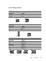
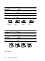
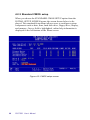
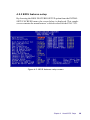
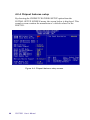
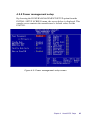
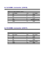
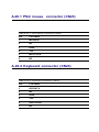
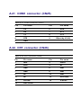
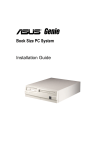
1
POS-7551
Geode™ FlexATX SBC for POS
Applications
User's Manual for POS-7551
Copyright notice
This document is copyrighted, 2001. All rights are reserved. The
original manufacturer reserves the right to make improvements to
the products described in this manual at any time without notice.
No part of this manual may be reproduced, copied, translated or
transmitted in any form or by any means without the prior written
permission of the original manufacturer. Information provided in
this manual is intended to be accurate and reliable. However, the
original manufacturer assumes no responsibility for its use, nor for
any infringements upon the rights of third parties which may result
from its use.
Acknowledgements
VIA is a trademark of Silicon Integration Systems Corp.
AMD is a trademark of Advanced Micro Devices, Inc.
Award is a trademark of Award Software International, Inc.
Cyrix is a trademark of Cyrix Corporation.
IBM, PC/AT, PS/2 and VGA are trademarks of International
Business Machines Corporation.
Intel and Pentium are trademarks of Intel Corporation.
Microsoft Windows® is a registered trademark of Microsoft Corp.
SMC is a trademark of Standard Microsystems Corporation.
C&T is a trademark of Chips and Technologies, Inc.
UMC is a trademark of United Microelectronics Corporation.
RTL is a trademark of Realtek Semi-Conductor Co., Ltd.
All other product names or trademarks are properties of their
respective owners.
Part No. 2006755100
1st Edition Published in Taiwan April 2001
POS-7551 User's Manual
Packing List
Before installing your board, insure that the following materials
have been received:
• 1 POS-7551 all-in-one single board computer
• 1 CD-ROM or disks for utility, drivers, and manual (in PDF
format)
• 1 warranty certificate
• 1 FDD cable
• 1 UDMA/33 IDE flat cable
• 1 startup manual
If any of these items are missing or damaged, contact your distributor or sales representative immediately.
Preface and Table of Contents
Table of Contents
Chapter 1 General Information ................... 1
1.1 Introduction ........................................................................... 2
1.2 Features ................................................................................ 3
1.3 Specifications ....................................................................... 4
Standard SBC functions .............................................................. 4
Ethernet Interface ......................................................................... 5
Audio Function (POS-7551F only) ............................................... 5
Digital I/O ...................................................................................... 5
Mechanical and Environmental ................................................... 5
1.4 Board dimensions ................................................................ 6
Chapter 2 Installation................................... 7
2.1
2.2
2.3
2.4
2.5
2.6
2.7
2.8
2.9
2.10
2.11
2.12
2.13
2.14
2.15
2.16
2.17
2.18
2.19
Jumpers ................................................................................. 8
Connectors ............................................................................ 8
Locating Jumpers and Connectors ................................... 10
Safety Precautions ............................................................. 13
Setting jumpers .................................................................. 14
Flat panel display connector (CN15) ................................. 18
Digital I/O (CN5: 2 Outputs, 2 Inputs) ................................. 19
CompactFlash™ I/II connector (CN27) .............................. 20
USB connector (CN21) ........................................................ 20
Audio interfaces (CN19, CN24, CN20) ................................ 21
40-pin Primary IDE (3.5" HDD) Connector (CN10) ............. 22
FDD connector (CN9) .......................................................... 23
44-pin Secondary Mini-pitched IDE Interface
(2.5" HDD or SSD) (CN8) ..................................................... 24
VGA interface connections ................................................ 24
Power connectors (CN14) ................................................... 25
IR connector (CN7) .............................................................. 25
Serial ports (COM1 - 4) (CN18/25, CN17, CN16, CN13)....... 25
Keyboard/mouse connectors (CN23) ................................. 26
LPT1 (primary parallel port) connector (CN22) ................ 26
POS-7551 User's Manual
2.20 LPT2 (secondary parallel port) connector (CN14) ............ 26
2.21 Ethernet configuration ....................................................... 27
2.22 Watchdog Programming Sample ...................................... 27
Chapter 3 Software Configuration ........... 29
3.1
3.2
3.3
3.4
3.5
4.1
4.2
Introduction ......................................................................... 30
Utility CD disk ...................................................................... 30
BIOS Program Setup .......................................................... 31
Connections for two standard LCDs .................................. 32
Ethernet interface configuration ....................................... 34
System test and initialization ............................................ 36
Award BIOS setup .............................................................. 37
4.2.1 Entering setup .................................................................. 37
4.2.2 Standard CMOS setup ...................................................... 38
4.2.3 BIOS features setup ......................................................... 39
4.2.4 Chipset features setup ..................................................... 40
4.2.5 Power management setup ............................................... 41
4.2.6 PnP/PCI configuration setup ............................................ 42
4.2.7 Integrated peripherals ...................................................... 43
4.2.8 Load BIOS defaults ........................................................... 43
4.2.9 Change password ............................................................ 44
4.2.10 Auto detect hard disk ...................................................... 45
4.2.11 Save & exit setup ............................................................. 45
4.2.12 Exit without saving .......................................................... 45
4.2.8 Load BIOS defaults ........................................................... 46
Chapter 5 VGA and Audio Setup .............. 47
5.1 Introduction ......................................................................... 48
5.1.1 Chipset (NS CX5530A) (POS-7551) ................................ 48
5.1.2 Display memory ............................................................... 48
5.2 Installation of CX5530A chipset VGA and Audio driver ... 49
5.2.1 Installation for Windows 3.1 (VGA only) ........................... 50
5.2.2 Installation for Windows 95/98 VGA and Audio ................ 53
5.3 Installation for Windows NT Audio (CX5530A) .................... 57
5.4 Installation for Windows NT VGA for CX5530A .................. 61
Preface and Table of Contents
Chapter 6 PCI Bus Ethernet Interface ..... 65
6.1 Introduction ......................................................................... 66
6.2 Installation of Ethernet driver ............................................ 66
6.2.1 Installation for MS-DOS and Windows ............................. 66
6.2.1 Installation for Windows 95/98 ......................................... 67
6.2.2 Installation for Windows NT ............................................. 72
Appendix A Pin Assignments ................... 75
A.1 LCD brightness adjust connector (CN1) ............................ 76
A.2 LCD contrast adjust connector (CN2) ............................... 76
A.3 System function connector (CN3) ...................................... 77
A.5 Digital I/O (CN5) .................................................................. 78
A.4 ATX power connector (CN4) ............................................... 78
A.6 LCD backlight connector (CN6) .......................................... 79
A.7 IR connector (CN7) .............................................................. 79
A.8 Secondary slave IDE connector (CN8) ............................. 80
A.9 FDD connector (CN9) .......................................................... 81
A.10 Primary IDE connector (CN10) ........................................... 82
A.13 COM4 connector (CN13) ..................................................... 83
A.14 LPT2 connector (CN14) ....................................................... 83
A.15 LCD 18 bit connectorFor Cyrix chipsets (CN15) ................ 84
A.16 COM3 connector (CN16) ..................................................... 85
A.17 COM2 connector (CN17) ..................................................... 85
A.19 Audio connector (CN19) ..................................................... 86
A.18 COM1 connector (CN18) ..................................................... 86
A.20 CD audio-in connector (CN20) ........................................... 87
A.22 LPT1 connector (CN22) ...................................................... 87
A.23.1 PS/2 mouse connector (CN23) ....................................... 88
A.23.2 Keyboard connector (CN23) ............................................ 88
A.26 CRT connector (CN26) ....................................................... 89
A.25 COM1 connector (CN25) .................................................... 89
POS-7551 User's Manual
Figures
Figure 1-1: Board dimensions (component side) ..................................... 6
Figure 2-1: Locating jumpers .................................................................. 10
Figure 2-2: Locating connectors ............................................................. 11
Figure 2-3: Backside connectors ............................................................ 12
Figure 3-1: Contents of the POS-7551 Series utility disk ....................... 30
Figure 3-2: BIOS program setup screen ................................................. 31
Figure 4-1: Setup program initial screen ................................................ 37
Figure 4-2: CMOS setup screen .............................................................. 38
Figure 4-3: BIOS features setup screen .................................................. 39
Figure 4-4: Chipset features setup screen .............................................. 40
Figure 4-5: Power management setup screen ....................................... 41
Figure 4-6: PCI configuration setup screen ............................................ 42
Figure 4-7: Integrated peripherals setup screen .................................... 43
Preface and Table of Contents
Tables
Table 2-1: Connectors ............................................................................................... 8
Table 2-2: Connectors ............................................................................................... 8
Table 2-3: Digital output programming ..................................................................... 19
Table A-1: LCD brightness adjust Connector (CN1) ............................................... 76
Table A-2: LCD contrast adjust Connector (CN2) .................................................. 76
Table A-3: System function connector (CN3) ........................................................ 77
Table A-5: Digital I/O (CN2) ...................................................................................... 78
Table A-4: ATX power connector (CN4) ................................................................ 78
Table A-6: LCD backlight Connector (CN6) ............................................................. 79
Table A-7: IR Connector (CN7) ................................................................................ 79
Table A-8: Secondary slave Connector (CN8) ....................................................... 80
Table A-9: FDD connector (CN0) ............................................................................ 81
Table A-10: Primary IDE Connector (CN10) ............................................................ 82
Table A-13: COM4 connector (CN13) ..................................................................... 83
Table A-14: LPT2 connector (CN14) ....................................................................... 83
Table A-16: COM3 connector (CN16) ..................................................................... 85
Table A-17: COM2 connector (CN17) ..................................................................... 85
Table A-19: Audio connector (CN19) ..................................................................... 86
Table A-18: COM1 connector (CN18) ..................................................................... 86
Table A-20: CD audio-in connector (CN20) ............................................................ 87
Table A-22: LPT1 connector (CN22) ....................................................................... 87
Table A-23.1: PS/2 Mouse Connector (CN23) ........................................................ 88
Table A-23.2: Keyboard Connector (CN23) ........................................................... 88
Table A-26: CRT connector (CN26) ........................................................................ 89
Table A-25: COM1 connector (CN25) ..................................................................... 89
POS-7551 User's Manual
CHAPTER
1
General Information
This chapter gives background information
on the POS-7551.
Sections include:
• Introduction
• Features
• Specifications
• Board layout and dimensions
Chapter 1 General Information
1
1.1 Introduction
The POS-7551 is a low cost, fanless Geode GX1-233 FlexATX board
especially designed for POS applications. The POS-7551 is made with
industrial grade construction that can better withstand constant 24
hour a day use, high vibration, shock, exposure to humidity, moisture
and heat. The GX1-233 processor allows for fanless operation that
virtually eliminates heat buildup problems that has traditionally been
the number one cause of failure in enclosed POS systems.
The POS-7551 has one PCI slot, one ISA expansion slot, two digital I/
Os and four on-board serial ports each with +5 V/+12 V power. These
flexible I/Os have standard OLE interfacing that allow for application
hardware independence to be realized. Peripherals ranging from bar
code scanners, card readers, printers, cash drawers etc., are all easily
supported. The POS-7551 uses a standardized layout based on
FlexATX form factor. It is 100% PC compatible and ready for any
existing PC software or hardware.
Other on-board industrial features not found on conventional motherboards include a watchdog timer for dependability during unmanned
operations, and CMOS backup to Flash ROM. The optional CompactFlash™ card can also be use to support memory modules.
2
POS-7551 User's Manual
1.2 Features
• NS Geode™ GX1-233 processor on board
• Fanless operation
• VGA/LCD controller with Universal Memory Architecture
• Supports 18 bit TFT display
• 10/100 Mbps PCI ethernet interface with wake-on-LAN support
• 4 COM ports with power line support in Pin 9
• Digital I/O (2 in & 2 out)
• 2 parallel ports
• 2 x USB
• 4 Mbps FIR
• Socket for CompactFlash™ card (POS-7551F only)
• Watchdog timer: Software enabled/disabled 1 ~255 minutes selectable.
• AC97 audio interface (POS-7551F only)
• 16 MB onboard DRAM (POS-7551F only)
Chapter 1 General Information
3
1.3 Specifications
Standard SBC functions
• CPU: Embedded low power NS Geode GX1-233
• BIOS: 2 Mbit Flash BIOS, supports Plug & Play, APM
1.2,
Supports Ethernet boot ROM, boot from CD-ROM and boot from
LS-120 ZIP Drive, optional customer icon available.
• Chipset: CX 5530A
• System memory: One DIMM socket accepts 8 ~ 128 MB SDRAM (8/
16/32/64/128 MB)
16 MB onboard DRAM (POS-7551F only)
• Enhanced IDE interface: Supports up to four EIDE devices. BIOS
auto-detect, PIO Mode 3 or Mode 4 transfer, Ultra DMA33 mode
(ATA-4) up to 33 MB/sec
• FDD interface: Supports 360K/1.2M/720K/1.44MB/2.88MB up to two
FDDs
• Serial ports: Four serial RS-232 ports, COM1,2, 3, 4, all provide power
support
• Parallel port: Two parallel ports, supports EPP/ECP mode
• Infrared port: Shared with COM4. Transfer rates up to 4 Mbps
• Keyboard/mouse connector: Supports standard PS/2 keyboard and a
PS/2 mouse
• Power management: Supports power saving modes including
Normal/Standby modes. APM 1.1 compliant
• Watchdog timer: 1 ~ 255 minutes selectable
• USB: Two universal serial bus ports: Compliant with USB Spec.
Rev. 1.10
4
POS-7551 User's Manual
Ethernet Interface
• Chipset: RTL 8139C
• Ethernet interface: PCI 10/100 Mbps Ethernet. IEEE 802.3 U
protocol compatible
• Connection: On-board RJ-45 connector
• I/O address switchless setting
• Built-in boot ROM
Audio Function (POS-7551F only)
• Audio controller: AC97 version 2.0 compliant interface
• Audio interface: Microphone in, line in, CD audio in, line out,
speaker L and Speaker R
Digital I/O
• Two digital inputs and outputs
Mechanical and Environmental
• Dimensions (L x W): 229 x 191 mm (9.0" x 7.5")
• Power supply voltage: +5 V ±5 %
• Power requirements: typical 5 [email protected] A (w/ GX1-233 MHz CPU
& 128 MB RAM)
• Operating temperature: 0 ~ 60° C (32 ~ 140° F)
• Weight: 0.5 kg (1.1 lb)
Chapter 1 General Information
5
1.4 Board dimensions
Figure 1-1: Board dimensions (component side)
6
POS-7551 User's Manual
CHAPTER
2
Installation
This chapter explains how to set up the
POS-7551 hardware, including instructions on
setting jumpers and connecting peripherals,
switches and indicators. Be sure to read all the
safety precautions before you begin the
installation procedure.
Chapter 2 Installation
7
2.1 Jumpers
The POS-7551 has a number of jumpers that allow you to configure
your system to suit your application. The table below lists the function
of each of the board's jumpers.
Table 2-1: Connectors
Label
Function
J1 CN15 LCD Voltage select
J2 Clear RTC
J3 COM3, COM4 Voltage select
J4 COM3, COM4 Ring/Voltage select
J5 COM1, COM2 Ring/Voltage select
J6 COM1, COM2 Voltage select
SW1
Share IRQ select
2.2 Connectors
On-board connectors link the POS-7551 to external devices such as
hard disk drives, a keyboard, or floppy drives. The tables below lists
the function of each of the board's connectors.
Table 2-2: Connectors
Label
8
Function
CN1
LCD Brightness adjustor connector
CN2
LCD Contrast adjustor connector
CN3
System Function connector
CN4
ATX Power connector
CN5
Digital I/O connector
POS-7551 User's Manual
CN6
LCD Backlight connector
CN7
IR connector
CN8
Secondary Slaver IDE connector
CN9
FDD connector
CN10
Primary IDE connector
CN11
ISA Slot
CN12
PCI Slot
CN13
COM4 connector
CN14
LPT2 connector
CN15
LCD 24Bit connector: Color bits for 18-bit TFT LCD
CN16
COM3 connector
CN17
COM2 connector
CN18
COM1 connector
CN19
Audio connector
CN20
CDROM Audio-In connector
CN21
LAN, USB1, USB2 connectors
CN22
LPT1 connector
CN23
PS/2 Keyboard, mouse connector
CN24
Line in, Microphone in & speaker out
CN25
COM1 connector
CN26
CRT connector
CN27
CompactFlash™ socket
Chapter 2 Installation
9
2.3 Locating Jumpers and Connectors
Figure 2-1: Locating jumpers
10
POS-7551 User's Manual
Figure 2-2: Locating connectors
Chapter 2 Installation
11
Figure 2-3: Backside connectors
12
POS-7551 User's Manual
2.4 Safety Precautions
The following sections tell how to make each connection. In most
cases, you will simply need to connect a standard cable.
Warning! Always completely disconnect the power cord from
your chassis whenever you are working on it. Do not
make connections while the power is on. Sensitive
electronic components can be damaged by a
sudden rush of power. Only experienced electronics
personnel should open the PC chassis.
Caution!
Always ground yourself to remove any static charge
before touching the CPU card. Modern electronic
devices are very sensitive to static electric charges.
Use a grounding wrist strap at all times. Place all
electronic components on a static-dissipative surface
or in a static-shielded bag when they are not in the
chassis.
Chapter 2 Installation
13
2.5 Setting jumpers
2.5.1 Introduction
You may configure your card to match the needs of your application
by setting jumpers. A jumper is the simplest kind of electrical switch.
It consists of two metal pins and a small metal clip (often protected by
a plastic cover) that slides over the pins to connect them. To "close" a
jumper, you connect the pins with the clip. To "open” a jumper you
remove the clip. Sometimes a jumper will have three pins, labeled 1,
2, and 3. In this case you would connect either pins 1 and 2 or 2 and 3.
1
Open
Closed
2
3
Closed 2-3
The jumper settings are schematically depicted in this manual as
follows:
Open
Closed
Closed 2-3
A pair of needle-nose pliers may be helpful when working with
jumpers.
If you have any doubts about the best hardware configuration for your
application, contact your local distributor or sales representative
before you make any changes.
Generally, you simply need a standard cable to make most connections.
14
POS-7551 User's Manual
2.5.2 Settings details
J1: CN15 LCD voltage select
Closed pins
Result
1-3, 2-4
+5 V*
3-5, 4-6
+3.3 V
2
2
1
1
+5 V*
+3.3 V
J2: Clear RTC
Closed pins
Result
1-2
Clear RTC
2-3
RTC*
1
1
Clear RTC
RTC*
J3: COM3, COM4 Voltage select
Closed pins
COM 3
2-4
COM3 +5 V*
4-6
COM3 +12 V
Closed pins
COM 4
1-3
COM4 +5 V*
3-5
COM4 +12 V
2
2
2
2
1
1
1
1
+5V*
+12V
+5V*
+12V
Chapter 2 Installation
15
J4: COM3, COM4 Ring/Voltage select
Closed pins
COM 3
2-4
Voltage
4-6
Ring*
Closed pins
COM 4
1-3
Voltage
3-5
Ring*
2
2
1
2
1
Voltage
1
Voltage
Ring*
2
1
Ring*
J5: COM1, COM2 Ring/Voltage select
Closed pins
COM 1
2-4
Voltage
4-6
Ring*
Closed pins
COM 2
1-3
Voltage
3-5
Ring*
Voltage
Ring*
*Default settings
16
POS-7551 User's Manual
Voltage
Ring*
J6: COM1, COM2 Voltage select
Closed pins
COM 1
2-4
+5V*
4-6
+12V
Closed pins
COM 2
1-3
+5V*
3-5
+12V
+5V*
+12V
+5V*
+12V
SW1: Share IRQ select
1,2,3
IRQ4:COM1, IRQ3:COM2, IRQ10:COM3,
IRQ5:COM4
2,3
IRQ10: COM1, COM2, COM3, COM4
1,3
IRQ5: COM1, COM2, COM3, COM4
3
IRQ3: COM1, COM2, COM3, COM4
1,2
IRQ4: COM1, COM2, COM3, COM4
2
IRQ4: COM1, COM3; IRQ3: COM2, COM4
1
IRQ4: COM1; IRQ3: COM2; IRQ10: COM3, COM4
None
IRQ4: COM1; IRQ3: COM2, COM3, COM4
4 3 2 1
Result
ON
ON
Chapter 2 Installation
17
2.6 Flat panel display connector (CN15)
CN1 consists of a 44-pin, dual-in-line header.
The power supply (+12 V) for CN1 is dependant on the supply
connected to the board. Therefore make sure that CN4 is connected to
a +12 V power supply.
The POS-7551 provides a bias control signal on CN1 which can be
used to control the LCD bias voltage. It is recommended that the LCD
bias voltage not be applied to the panel until the logic supply voltage
(+5 V or +3.3 V) and panel video signals are stable. Under normal
operation the control signal (ENAVEE) is active high. When the POS7551 board's power is applied, the control signal is low until just after
the relevant flat panel signals are present.
18
POS-7551 User's Manual
2.7 Digital I/O (CN5: 2 Outputs, 2 Inputs)
The POS-7551 has two TTL level digital outputs address 550h, and two
TTL level digital inputs (address 551h). You can configure the digital I/
O to control the opening of the cash drawer and to sense the closing
of the cash drawer. The following explains how the digital I/O is
controlled via software programming.
Digital I/O Connector
+5V
1
2
+5 V
+12V
3
4
+12V
DI/O OUT 0
5
6
DI/O OUT 1
D I/O In 0
7
8
DI/O IN 1
GND
9
10
GND
2.7.1 Digital output programming
Output is TTL type.
Table 2-3: Digital output programming
Output
Address
Bit
Out 1
550
1
Out 2
550
2
Example: ("0" = off "1" = on)
Data 00 = Out 0 and Out 1 = "0"
Data 02 = Out 0 = "1"
Data 04 = Out 1 = "1"
Data 06 = Out 0 and Out 1 = "1"
Chapter 2 Installation
19
2.8 CompactFlash™ I/II connector (CN27)
The POS-7551 Series is equipped with a CompactFlash disk socket that
supports an IDE interface CompactFlash disk card. The socket itself is
especially designed to prevent any incorrect installation of the
CompactFlash disk card. When installing or removing the CompactFlash disk card, please make sure that the system power is off.
The CompactFlash disk card is defaulted as the Secondary IDE Master
HDD in your PC system.
2.9 USB connector (CN21)
The POS-7551 board provides two USB (Universal Serial Bus) interfaces which support plug and play and hot attach/detach for up to 127
external devices. The USB interfaces comply with USB specification
Rev. 1.0 and are fuse protected.
The USB interfaces can be disabled in the system BIOS setup.
20
POS-7551 User's Manual
2.10 Audio interfaces (CN19, CN24, CN20)
The POS-7551 is equipped with a high quality audio interface, which
provides 16-bit CD-quality recording and playback as well as OPL3
compatible FM music. It is supported by all major operating systems
and is 100% Sound Blaster Pro compatible.
2.10.1 Audio connector (CN19, CN24)
The POS-7551 provides all major audio signals on a 16-pin flat-cable
connector, CN19. These audio signals include Microphone in (mono),
Line in (stereo), Line out (stereo), and Speaker out (stereo). You will
need an adapter cable if you use traditional telephone jack connectors
for these audio signals. The other CN24 connectors include line out,
line in and microphone in accordance with PC98 standard.
2.10.2 CD audio-in connector (CN20)
All CD-ROM drives can provide analog audio signal output when
used as a music CD player. The CN20 on POS-7551 is a connector to
input CD audio signal into the audio controller. The audio cable of
your CD-ROM drive will be used to connect to CN20.
Chapter 2 Installation
21
2.11 40-pin Primary IDE (3.5" HDD)
Connector (CN10)
The 40-pin IDE connector (CN10) supports up to two 40-pin IDE
interface devices, including CD-ROM drives, tape-backup drives,
HDDs, etc. When connecting, make sure pin 1 of the connector is
matched with pin 1 of the device's connector.
The built-in Enhanced IDE (Integrated Device Electronics) controller
supports up to two IDE channels, including CD-ROM drives, tape
backup drives, a large hard disk drive and other IDE devices. It also
supports faster data transfer rates and allows IDE hard disk drives
with capacities in excess of 528 MB.
Connecting the hard drive
Connecting drives is done in a daisy-chain fashion. Wire number 1 on
the cable is red or blue, while the other wires are gray.
Unlike floppy drives, IDE hard drives can connect to either end of the
cable. If you install two drives, you will need to set one as the master
and one as the slave by using jumpers on the drives. If you install just
one drive, set it as the master.
22
POS-7551 User's Manual
2.12 FDD connector (CN9)
You can attach up to two floppy disks to the POS-7551's on-board
controller. You can use any combination of 5¼" (360 KB and 1.2 MB)
and/or 3½" (720 KB, 1.44 MB, and 2.88 MB) drives.
A 34-pin daisy-chain drive connector cable is required for a dualdrive system. On one end of the cable is a 34-pin flat-cable connector.
On the other end are two sets of floppy disk drive connectors. Each
set consists of a 34-pin flat-cable connector (usually used for 3½"
drives) and a printed-circuit board connector (usually used for 5¼"
drives).
2.12.1 Connecting the floppy drive
1. Plug the 34-pin flat-cable connector into CN9. Make sure that the
red wire corresponds to pin one on the connector.
2. Attach the appropriate connector on the other end of the cable to
the floppy drive(s). You can use only one connector in the set. The
set on the end (after the twist in the cable) connects to the A: drive.
The set in the middle connects to the B: drive.
3. If you are connecting a 5¼" floppy drive, line up the slot in the
printed circuit board with the blocked-off part of the cable
connector.
If you are connecting a 3½" floppy drive, you may have trouble
determining which pin is pin number one. Look for a number
printed on the circuit board indicating pin number one. Also, the
connector on the floppy drive connector may have a slot. When
the slot is up, pin number one should be on the right. Check the
documentation that came with the drive for more information.
The B: drive can be attached to the connectors in the middle of the
cable as described above.
Chapter 2 Installation
23
2.13 44-pin Secondary Mini-pitched IDE
Interface (2.5" HDD or SSD) (CN8)
The on-board 44-pin mini-pitched IDE interface allows users to
support either a 2.5" HDD or a Sandisk IDE Flash module (P/N: PCD1230-2M/4M) that is available in both 2 and 4 MB versions.
Follow the same connection arrangement as the 3.5" HDD if you want
to connect to a 2.5" IDE device. Read the BIOS setup section for
more information regarding system settings.
2.14 VGA interface connections
The POS-7551 's VGA interface can drive conventional CRT displays
and is capable of driving a wide range of flat panel displays, including
electroluminescent (EL), gas plasma, passive LCD and active LCD
displays. The board has two connectors to support these displays, one
for standard CRT VGA monitors and one for flat panel displays.
2.14.1 CRT display connector (CN26)
CN26 is a standard 15-pin D-SUB connector commonly used for the CRT
VGA monitor only. Pin assignments appear in the appendix.
2.14.2 Flat panel display connector (CN15)
CN14 consists of a 44-pin, dual inline header. It can connect to a 24-bit
TFT LCD panel. Pin assignments appear in the appendix.
2.14.3 LCD power setting (J1)
The POS-7551's VGA interface supports 5 V and 3.3 V LCD displays.
By changing the setting of J1, you can select the panel video power
level to be 5 V or 3.3 V.
24
POS-7551 User's Manual
2.15 Power connectors (CN14)
2.15.1 ATX power input connector (CN14)
The power connection is a 20-pin connector requiring ±5 V and ±12 V
and 5VSB single.
2.16 IR connector (CN7)
The POS-7551 provides an IrDA port. This connector supports the
optional wireless infrared transmitting and receiving module, which is
mounted on the system case. Configuration of the module is done
through BIOS setup.
2.17 Serial ports (COM1 - 4) (CN18/25, CN17,
CN16, CN13)
The POS-7551 has a total of four on-board RS-232 serial ports, COM14. All four serial ports have +5 V and +12 V power capabilities on pin
#9, (CN25) pin # 8 (CN18/17/16/13) depending on the jumper setting.
Pin assignments for both internal and external COM ports can be
found in the appendix.
2.17.1 Primary serial ports (COM1: CN18/25, COM2:
CN17)
COM 1 has two connections, one external DB-9 and one internal 10pin header giving the user the flexibility to adapt the board to many
different systems. IRQ for COM1 and COM2 is default with COM1 on
IRQ4 and COM2 on IRQ3. COM1 and COM2 can be enabled or
disabled via BIOS (see Chapter 4).
2.17.2 Secondary serial ports (COM3: CN16, COM4:
CN13)
The secondary serial ports each have one 10-pin, internally positioned
header connection. The IRQ for COM3 is fixed at IRQ10 and COM4
is fixed at IRQ5. COM3 and COM4 can be enabled/disabled via BIOS
(see Chapter 4).
Chapter 2 Installation
25
2.18 Keyboard/mouse connectors
(CN23)
The POS-7551 is uniquely designed to keyboard and mouse input.
2.19 LPT1 (primary parallel port)
connector (CN22)
The primary parallel printer port is located at the rear edge of the
board, and has a DB-25 connector. This printer port is typically used
to connect a printer via an adapter cable. LPT1's IRQ setting is
defined as IRQ7. You can select Normal/EPP/ECP for LPT1, and
enable/disable it in BIOS (see Chapter 4).
2.20 LPT2 (secondary parallel port)
connector (CN14)
This secondary port has a 26-pin box header. LPT2’s IRQ setting is
defined as IRQ9. You can select Printer/EPP/ECP/SPP for LPT2, and
enable/disable it in BIOS (see Chapter 4).
26
POS-7551 User's Manual
2.21 Ethernet configuration
The POS-7551 is equipped with a high performance 32-bit PCI-bus
Ethernet interface which is fully compliant with IEEE 802.3 u
10/100Mbps CSMA/CD standards. It is supported by all major network
operating systems.
The medium type can be configured via the RSET8139.EXE program
included on the utility disk (see Chapter 3 for detailed information).
2.21.1 RJ-45 connector (CN21)
100/10Base-T connects to the POS-7551 via an RJ-45 standard jack.
2.21.2 Network boot
The Network Boot feature can be utilized by incorporating the Boot
ROM image files for the appropriate network operating system. You
can enable or disable it in BIOS.
2.22 Watchdog Programming Sample
Debug Program
Result
-o 370 87
-o 370 87
OPEN 2nd SUPER I/O
-o 370 2c
-o 371 15
Set Pin119 to GP16, Pin 104 to
GP15, Pin 103 to GP14
-o 370 07
-o 371 07
Set device 07
-o 370 e6
-o 371 0a
Set GP16 to WDT
-o 370 07
-o 371 08
Set device 08
-o 370 f2
-o 371 01
00 : disable,01 : time out after 1
min,02 : time out after 1 min....FF :
time out after 255 min
Chapter 2 Installation
27
28
POS-7551 User's Manual
CHAPTER
3
Software Configuration
This chapter details the software configuration information. It shows you how to
configure the card to match your application requirements. Award system BIOS is
covered in Chapter 4.
Sections include:
• Connections for two standard LCDs
Chapter 3 Software Configuration
29
3.1
Introduction
The POS-7551 system BIOS and custom drivers are located in a 256
KB, 32-pin Flash ROM device, designated U21. A single Flash chip
holds the system BIOS and VGA BIOS.
3.2
Utility CD disk
The POS-7551 is supplied with a software utility on CD-ROM. This
disk contains the necessary file for setting up the VGA display.
Directories and files on the disk are as follows:
AWDFLASH.EXE
CBROM.EXE
RSET8139.EXE
P561V111.BIN
Figure 3-1: Contents of the POS-7551 Series utility disk
AWDFLASH.EXE
This program allows you to update the BIOS Flash ROM.
PxxxBIN
This binary file contains the system BIOS.
CBROM.EXE
This program allows you to combine your own VGA BIOS with
system BIOS.
RSET8139.EXE
This program enables you to view the current Ethernet configuration, reconfigure the Ethernet interface (medium type, etc.), and
execute useful diagnostic functions.
30
POS-7551 User's Manual
3.3
BIOS Program Setup
Note:
Make sure that you do not run AWDFLASH.EXE
while your system is operating in EMM386 mode.
1. At the prompt, type AWDFLASH.EXE and press <Enter>. The
VGA configuration program will then display the following:
Figure 3-2: BIOS program setup screen
2. At the prompt, type in the BIN file which supports your
display. When you are sure that you have entered the file name
correctly press <Enter>. The screen will ask “Do you want to
save?” If you wish to continue press Y. If you change your
mind or have made a mistake press N.
3. If you decide to continue, the screen will issue a prompt which
will then ask “Are you sure to program (Y/N)?” If you wish to
continue, press Y. Press N to exit the program.
The new VGA configuration will then write to the ROM BIOS
chip. This configuration will remain the same until you run the
AWDFLASH.EXE program and change the settings.
Chapter 3 Software Configuration
31
3.4
Connections for two standard LCDs
3.4.1 Connections for Toshiba LTM10C042
(640 x 480 TFT color LCD)
Table 3-1: Connections for Toshiba LTM10C042
LTM10C042
Pin
Name
1
GND
2
CLK
3
GND
4
R0
5
R1
6
R2
7
GND
8
R3
9
R4
10
R5
11
GND
12
G0
13
G1
14
G2
15
GND
16
G3
17
G4
18
G5
19
GND
20
ENAB
21
GND
22
B0
23
B1
24
B2
25
GND
26
B3
27
B4
28
B5
29
GND
30
VDD
31
VDD
32
POS-7551 User's Manual
POS-7551 CN15
Pin
Name
3
GND
35
SHFCLK
4
GND
27
PD12
28
PD13
29
PD14
8
GND
30
PD15
31
PD16
32
PD17
33
GND
19
PD6
20
PD7
21
PD8
33
GND
22
PD9
23
PD10
24
PD11
34
GND
37
M
34
GND
11
PD0
12
PD1
13
PD2
39
GND
14
PD3
15
PD4
16
PD5
39
GND
5
+5 V
6
+5 V
3.4.2 Connections for Toshiba LTM12C275A
(800 x 600 TFT color LCD)
Table 3-2: Connections for Toshiba LTM12C275A
LTM12C275A
Pin
Name
POS-7551 CN15
Pin
Name
1
GND
3
GND
2
NCLK
35
SHFCLK
3
NC
-
NC
4
NC
-
NC
5
GND
4
GND
6
R0
27
PD12
7
R1
28
PD13
8
R2
29
PD14
9
R3
30
PD15
10
R4
31
PD16
11
R5
32
PD17
12
GND
8
GND
13
G0
19
PD6
14
G1
20
PD7
15
G2
21
PD8
16
G3
22
PD9
17
G4
23
PD10
18
G5
24
PD11
19
GND
33
GND
20
B0
11
PD0
21
B1
12
PD1
22
B2
13
PD2
23
B3
14
PD3
24
B4
15
PD4
25
B5
16
PD5
26
ENAB
37
M/DE
27
GND
34
GND
28
VCC
5
+5 V
29
VCC
6
+5 V
30
GND
39
GND
Chapter 3 Software Configuration
33
3.5
Ethernet interface configuration
The POS-7551's on-board Ethernet interface supports all major
network operating systems. To configure the medium type, to view
the current configuration, or to run diagnostics, do the following:
1. Power the POS-7551 on. Make sure that the RSET8139.EXE file
is located in the working drive.
2. At the prompt, type RSET8139.EXE and press <Enter>. The
Ethernet configuration program will then be displayed.
3. This simple screen shows all the available options for the
Ethernet interface. Just highlight the option you wish to change
by using the Up and Down keys. To change a selected item,
press <Enter>, and a screen will appear with the available
options. Highlight your option and press <Enter>. Each
highlighted option has a helpful message guide displayed at the
bottom of the screen for additional information.
4. After you have made your selections and are sure this is the
configuration you want, press ESC. A prompt will appear
asking if you want to save the configuration. Press Y if you
want to save.
The Ethernet Setup Menu also offers three very useful diagnostic
functions. These are:
1. Run EEPROM test
2. Run Diagnostics on Board
3. Run Diagnostics on Network
Each option has its own display screen that shows the format and
result of any diagnostic tests undertaken.
34
POS-7551 User's Manual
CHAPTER
4
Award BIOS Setup
This chapter describes how to set BIOS
configuration data.
4.1 System test and initialization
These routines test and initialize board hardware. If the routines
encounter an error during the tests, you will either hear a few short
beeps or see an error message on the screen. There are two kinds of
errors: fatal and non-fatal. The system can usually continue the boot
up sequence with non-fatal errors. Non-fatal error messages usually
appear on the screen along with the following instructions:
press <F1> to RESUME
Write down the message and press the F1 key to continue the bootup
sequence.
4.1.1 System configuration verification
These routines check the current system configuration against the
values stored in the card’s CMOS memory. If they do not match, the
program outputs an error message. You will then need to run the
BIOS setup program to set the configuration information in memory.
There are three situations in which you will need to change the CMOS
settings:
1. You are starting your system for the first time.
2. You have changed the hardware attached to your system.
3. The CMOS memory has lost power and the configuration information has been erased.
The POS-7551’s CMOS memory has an integral lithium battery backup.
The battery backup should last ten years in normal service, but when it
finally runs down, you will need to replace the complete unit.
36
POS-7551 User's Manual
4.2 Award BIOS setup
Award’s BIOS ROM has a built-in Setup program that allows users to
modify the basic system configuration. This type of information is
stored in battery-backed CMOS RAM so that it retains the Setup
information when the power is turned off.
4.2.1 Entering setup
Power on the computer and press <Del> immediately. This will allow
you to enter Setup.
Figure 4-1: Setup program initial screen
Chapter 4 Award BIOS Setup
37
4.2.2 Standard CMOS setup
When you choose the STANDARD CMOS SETUP option from the
INITIAL SETUP SCREEN menu, the screen shown below is displayed. This standard Setup Menu allows users to configure system
components such as date, time, hard disk drive, floppy drive, display,
and memory. Once a field is highlighted, online help information is
displayed in the left bottom of the Menu screen.
Figure 4-2: CMOS setup screen
38
POS-7551 User's Manual
4.2.3 BIOS features setup
By choosing the BIOS FEATURES SETUP option from the INITIAL
SETUP SCREEN menu, the screen below is displayed. This sample
screen contains the manufacturer’s default values for the POS-7551.
Figure 4-3: BIOS features setup screen
Chapter 4 Award BIOS Setup
39
4.2.4 Chipset features setup
By choosing the CHIPSET FEATURES SETUP option from the
INITIAL SETUP SCREEN menu, the screen below is displayed. This
sample screen contains the manufacturer’s default values for the
POS-7551.
Figure 4-4: Chipset features setup screen
40
POS-7551 User's Manual
4.2.5 Power management setup
By choosing the POWER MANAGEMENT SETUP option from the
INITIAL SETUP SCREEN menu, the screen below is displayed. This
sample screen contains the manufacturer’s default values for the
POS-7551.
Figure 4-5: Power management setup screen
Chapter 4 Award BIOS Setup
41
4.2.6 PnP/PCI configuration setup
By choosing the PNP/PCI CONFIGURATION option from the INITIAL
SETUP SCREEN menu, the screen below is displayed. This sample
screen contains the manufacturer’s default values for the POS-7551.
Figure 4-6: PCI configuration setup screen
42
POS-7551 User's Manual
4.2.7 Integrated peripherals
By choosing the INTEGRATED PERIPHERALS option from the
INITIAL SETUP SCREEN menu, the screen below is displayed. This
sample screen contains the manufacturer’s default values for the
POS-7551.
Figure 4-7: Integrated peripherals setup screen
4.2.8 Load BIOS defaults
LOAD BIOS DEFAULTS loads the default system values directly
from ROM. If the stored record created by the Setup program becomes corrupted (and therefore unusable), these defaults will load
automatically when you turn the POS-7551 on.
Chapter 4 Award BIOS Setup
43
4.2.9 Change password
To change the password, choose the PASSWORD SETTING option
form the Setup main menu and press <Enter>.
1. If the CMOS is bad or this option has never been used, there is
default password which is stored in the ROM. The screen will
display the following messages:
Enter Password:
Press <Enter>.
2. If the CMOS is good or this option has been used to change the
default password, the user is asked for the password stored in the
CMOS. The screen will display the following message:
Confirm Password:
Enter the current password and press <Enter>.
3. After pressing <Enter> (ROM password) or the current password
(user-defined), you can change the password stored in the CMOS.
The password can be at most 8 characters long.
Remember - to enable this feature, you must first select either Setup or
System in the BIOS FEATURES SETUP.
44
POS-7551 User's Manual
4.2.10 Auto detect hard disk
The IDE HDD AUTO DETECTION utility can automatically detect
the IDE hard disk installed in your system. You can use it to selfdetect and/or correct the hard disk type configuration.
ROM PCI/ISA BIOS (2A5IHAKA)
CMOS SETUP UTILITY
AWARD SOFTWARE, INC.
HARD DISK TYPE
Drive C
:
SIZE
CYLS.
HEADS
PRECOMP
LANDZ
SECTORS MODE
(MB)
790
15
65535
789
57
Select Secondary Slave Option (N=Skip) : N
ESC = SKIP
Figure 4-9: IDE HDD auto detection screen
4.2.11 Save & exit setup
If you select this option and press <Enter>, the values entered in the
setup utilities will be recorded in the chipset's CMOS memory. The
microprocessor will check this every time you turn your system on
and compare this to what it finds as it checks the system. This record
is required for the system to operate.
4.2.12 Exit without saving
Selecting this option and pressing <Enter> lets you exit the Setup
program without recording any new values or changing old ones.
Chapter 4 Award BIOS Setup
45
46
POS-7551 User's Manual
CHAPTER
5
VGA and Audio Setup
(5530A chipset)
• Introduction
• Installation of SVGA driver for
Windows 3.1/9x/NT
Chapter 5 VGA Setup
47
5.1
Introduction
The POS-7551 has an on-board LCD/VGA interface. The specifications and features are described as follows:
5.1.1 Chipset (NS CX5530A) (POS-7551)
The POS-7551 uses a NS CX5530A chipset for its SVGA controller. It supports many popular 18-bit LCD displays and conventional
analog CRT monitors. The VGA BIOS supports LCD. In addition, it
also supports interlaced and non-interlaced analog monitors (color
and monochrome VGA) in high-resolution modes while maintaining
complete IBM VGA compatibility. Digital monitors (i.e. MDA, CGA,
and EGA) are NOT supported. Multiple frequency (multisync)
monitors are handled as if they were analog monitors.
5.1.2 Display memory
With 1.5 ~ 2.5 MB shared memory, the VGA controller can drive
CRT displays or color panel displays with resolutions up to 1280 x
1024 at 256 colors. The display memory can be expanded to 2.5
MB in BIOS for 64K color resolution of 1024 x 768.
48
POS-7551 User's Manual
5.2
Installation of CX5530A chipset VGA
and Audio driver
Complete the following steps to install the SVGA driver. Follow the
procedures in the flow chart that apply to the operating system that
you are using within your POS-7551.
Important: The following windows illustrations are examples
only. You must follow the flow chart instructions
and pay attention to the instructions which then
appear on your screen.
Note 1:
The CD-ROM drive is designated as "D:"
throughout this chapter.
Note 2:
<Enter> means pressing the “Enter” key on the
keyboard.
Note 3:
When you are using a CRT display, please make
sure that your flat panel resolution settings (in the
BIOS setup) are the same as your VGA resolution settings (in Windows). Otherwise your
display may behave strangely.
Chapter 5 VGA Setup
49
5.2.1 Installation for Windows 3.1 (VGA only)
1. In the Windows 3.1 Main screen, click on the "Windows
Setup" icon.
2. In the "Windows Setup" window, choose "Options", then select
"Change System Settings".
50
POS-7551 User's Manual
3. In the "Change System Settings" window, select the "Display"
item. In the dropdown selection, select "Other display {Requires disk from OEM}" .
4. Type in the correct path like the window below, where drive "D"
is the CD ROM drive. For example,
D:\POS\7551\CHIPSET\WIN31
D:\POS\7551\CHIPSET\WIN31
Chapter 5 VGA Setup
51
5. Select the display type and preferred resolution, then click
"OK".
6. Choose "Restart Windows".
52
POS-7551 User's Manual
5.2.2 Installation for Windows 95/98 VGA and Audio
Please note: when you setup VGA for 95/98, it installs
audio at the same time)
1. a. Browse
2. Choose "Open".
Chapter 5 VGA Setup
53
3. Type in the correct path like the window below, where drive "D"
is the CD ROM drive. For example,
D:\POS\7551\Chipset\Win9xc_12\National Geode"
D:\POS\7551\Chipset\Win9xc_12\NationalGeode
4. Cick "Finish".
54
POS-7551 User's Manual
5. Click "Next" to proceed to the next step.
6. Click "yes" after you read and accept the license agreement.
7. Click "next" after choosing the proper location.
Chapter 5 VGA Setup
55
8. Select typical, press next
9. Insert the Windows 98 CD-ROM, then click OK.
10. Choose "Yes", then click "Finish" to restart the computer.
56
POS-7551 User's Manual
5.3 Installation for Windows NT Audio (CX5530A)
1. a. Select "Start", "Settings", "Control panel".
b. Double click "Multimedia".
2. a. Select the "Devices" item.
b. Click "add".
Chapter 5 VGA Setup
57
3. a. Select the "unlisted.." item.
b. Click "OK".
4. a. Click "Browse".
5. Cick "OK".
7551
58
POS-7551 User's Manual
6. Type D:\POS\7551\Chipset\WINNT\Audio
D:\POS\7551\Chipset\WINNT\Audio
7. a. Choose the highlighted item.
b. Click the "OK" button.
8. a. Set the I/O address.
b. Click "Continue".
Chapter 5 VGA Setup
59
9. a. Set Xpress Audio configuration.
b. Click "OK".
4. Cick "Restart Now".
60
POS-7551 User's Manual
5.4 Installation for Windows NT VGA for CX5530A
1. a. Select "Start", "Settings", "Control Panel".
b. Double click the "Display" icon.
2. a. Choose the "Settings" label.
b. Press the "Display Type" button.
Chapter 5 PCI SVGA Setup
61
3 a. Press the "Change..." button.
4. Click the "Have Disk" button.
5. a. Insert the utility disc into the CD-ROM drive.
b. Type D:\POS\7551\chipset\winnt\vga
c. Press the "OK' button.
D:\POS\7551\chipset\winnt\vga
62
POS-7551 User's Manual
6 a. Select the highlighted item.
b. Press the "OK" button.
7. Press "Yes" to proceed.
8. a. Press "OK" to reboot.
Chapter 5 PCI SVGA Setup
63
9 a. Repeat Step 1 in this manual, to select the "Settings" label.
b. Adjust resolution and color.
c. Click "Test" to see the result.
d. Click "OK" to save the setting.
64
POS-7551 User's Manual
CHAPTER
6
PCI Bus Ethernet
Interface
This chapter provides information on
Ethernet configuration.
• Introduction
• Installation of Ethernet driver for
Windows 95/98/NT
• Further information
Chapter 6 PCI Bus Interface 65
6.1
Introduction
The POS-7551 is equipped with a high performance 32-bit Ethernet
chipset which is fully compliant with IEEE 802.3 100 Mbps CSMA/
CD standards. It is supported by major network operating systems.
It is also both 100Base-T and 10Base-T compatible. The medium
type can be configured via the RSET8139.exe program included on
the utility disk.
The Ethernet port provides a standard RJ-45 jack on board. The
network boot feature can be utilized by incorporating the boot
ROM image files for the appropriate network operating system. The
boot ROM BIOS files are combined with system BIOS, which can
be enabled/disabled in the BIOS setup.
6.2
Installation of Ethernet driver
Before installing the Ethernet driver, note the procedures below.
You must know which operating system you are using in your
POS-563, and then refer to the corresponding installation flow
chart. Then just follow the steps described in the flow chart. You
will quickly and successfully complete the installation, even if you
are not familiar with instructions for MS-DOS or Windows.
Note:
The windows illustrations in this chapter are
examples only. You must follow the flow chart
instructions and pay attention to the instructions
which then appear on your screen.
6.2.1 Installation for MS-DOS and Windows
If you want to set up your Ethernet connection under the MS-DOS
or Windows environment, you should first check your server
system model. For example, MS-NT, IBM-LAN server, and so on.
Then choose the correct driver to install in your panel PC.
66
POS-7551 User's Manual
Installation for Windows 95/98
1. a. Select "Start", "Settings", "Control Panel"
b. Double click "Network"
2. a. Click "add" and prepare to install network functions.
Chapter 6 PCI Bus Interface 67
3. a. Select the "Adaptor" item to add the ethernet card.
4. Cick "Have Disk" to install the driver.".
68
POS-7551 User's Manual
5. Click "Browse"
A:\
6. Select correct directory then click "OK".
7551
7. a. Insert the CD into the D:\drive.
b. Fill in "D:\POS\7551\LAN\WIN9x
c. Click "OK".
D:\POS\7551\LAN\WIN9x
Chapter 6 PCI Bus Interface 69
8. a. Choose the "Realtek" PCI item.
b. Click "OK".
9. Cick "OK".
10. Cick "OK".
70
POS-7551 User's Manual
11. Click "Yes".
Chapter 6 PCI Bus Interface 71
6.2.2 Installation for Windows NT
1. a. Select "Start", "Settings", "Control Panel".
b. Double click, "Network".
2. a. Choose the "Adaptors" label.
b. Click the "add" button.
72
POS-7551 User's Manual
3. Press "Have Disk".
4. a. Insert the CD into the D: \drive.
b. Fill in "D:\POS\7551\LAN\WINNT4"
c. Click "OK".
D:\POS\7551\LAN\WINNT4
5. a. Click "OK"
Chapter 6 PCI Bus Interface 73
6. a. Click "add".
6. a. Click "yes".
74
POS-7551 User's Manual
APPENDIX
A
Pin Assignments
This appendix contains information of a
detailed or specialized nature. It includes:
•
•
•
•
•
•
•
•
•
•
•
•
•
•
•
CD audio-in connector
Audio connector
ATX power connector
Primary (3.5") and secondary (2.5") IDE
connectors
Digital I/O
FDD connector
COM1 ~ COM4 RS-232 connections
FIR connector
LPT1/2 connectors (parallel port)
Contrast adjust connector
Backlight control
Brightness adjust connector
Flat panel display connector
CRT display connector
System function connector
A.1 LCD brightness adjust connector (CN1)
Table A-1: LCD brightness adjust Connector (CN1)
Pin
Pin Name
1
BRHI
2
BRIGHTNESS ADJ.
3
BRLOW
A.2 LCD contrast adjust connector (CN2)
Table A-2: LCD contrast adjust Connector (CN2)
Pin
Pin Name
1
CONHI
2
CONTRAST ADJ.
3
CONLOW
A.3 System function connector (CN3)
Table A-3: System function connector (CN3)
Pin
Pin name
Pin
Pin name
1
PW LED
2
+5V
3
PW LED
4
GND
5
GND
6
SPKB
7
KBLOCK*
8
SPKA
9
GND
10
NC
11
GND
12
HDDLED
13
PANSW*
14
GND
15
NC
16
NC
17
NC
18
FPRST
19
GND
20
GND
A.4 ATX power connector (CN4)
Table A-4: ATX power connector (CN4)
Pin
Pin name
Pin
Pin name
1
3.3V
11
3.3V
2
3.3V
12
-12V
3
GND
13
GND
4
+5V
14
PSON*
5
GND
15
GND
6
+5V
16
GND
7
GND
17
GND
8
PWROK
18
-5V
9
+5VSB
19
+5V
10
+12V
20
+5V
A.5 Digital I/O (CN5)
1
3
5
2
4
6
7
8
9
10
Table A-5: Digital I/O (CN5)
Pin
Pin name
Pin
Pin name
1
+5V
2
+5V
3
+12V
4
+12V
5
DI/O OUT 0
6
DI/O OUT 1
7
DI/O IN 0
8
DI/O IN 1
9
GND
10
GND
A.6 LCD backlight connector (CN6)
Table A-6: LCD backlight Connector (CN6)
Pin
Pin name
1
+12V
2
GND
3
ENABLE BACKLIGHT
4
BRIGHTNESS ADJ.
5
+5V
A.7 IR connector (CN7)
Table A-7: IR Connector (CN7)
Pin
Pin name
1
+5V
2
FIRIN
3
SIRIN
4
GND
5
SIROUT
A.8 Secondary slave IDE connector (CN8)
1
2
3
4
41
42
43
44
Table A-8: Secondary slave Connector (CN8)
Pin
Pin name
Pin
Pin name
1
IDE RESET*
2
GND
3
D7
4
D8
5
D6
6
D9
7
D5
8
D10
9
D4
10
D11
11
D3
12
D12
13
D2
14
D13
15
D1
16
D14
17
D0
18
D15
19
GND
20
NC
21
IDE DREQ
22
GND
23
IOW*
24
GND
25
IOR*
26
GND
27
CHRDY
28
NC
29
IDE DACK*
30
GND
31
IDE IRQ
32
NC
33
A1
34
NC
35
A0
36
A2
37
CS0*
38
CS1*
39
ACTIVE*
40
GND
41
+5V
42
+5V
43
GND
44
NC
A.9 FDD connector (CN9)
Table A-9: FDD connector (CN9)
1
2
Pin
Signal
3
4
1
GND
2
DENSITY SELECT*
3
GND
4
N/C
5
GND
6
DRIVE TYPE
7
GND
8
INDEX*
9
GND
10
MOTOR 0*
11
GND
12
DRIVE SELECT 1*
13
GND
14
DRIVE SELECT 0*
15
GND
16
MOTOR 1*
17
GND
18
DIRECTION*
19
GND
20
STEP*
21
GND
22
WRITE DATA*
23
GND
24
WRITE GATE*
25
GND
26
TRACK 0*
27
GND
28
WRITE PROTECT*
29
GND
30
READ DATA*
31
GND
32
HEAD SELECT*
33
GND
34
DISK CHANGE*
31
32
33
34
Pin
Signal
A.10 Primary IDE connector (CN10)
Table A-10: Primary IDE Connector (CN10)
Pin
Pin name
Pin
Pin nme
1
IDE RESET*
2
GND
3
D7
4
D8
5
D6
6
D9
7
D5
8
D10
9
D4
10
D11
11
D3
12
D12
13
D2
14
D13
15
D1
16
D14
17
D0
18
D15
19
GND
20
NC
21
IDE DREQ
22
GND
23
IOW*
24
GND
25
IOR*
26
GND
27
CHRDY
28
NC
29
IDE DACK*
30
GND
31
IDE IRQ
32
NC
33
A1
34
NC
35
A0
36
A2
37
CS0*
38
CS1*
39
ACTIVE*
40
GND
A.11 COM4 connector (CN13)
Table A-11: COM4 connector (CN13)
Pin
Pin name
Pin
Pin name
1
CD
2
DSR
3
RX
4
RTS
5
TX
6
CTS
7
DTR
8
9
GND
10
GND
RI(set by J3,J4)
A.12 LPT2 connector (CN14)
Table A-12: LPT2 connector (CN14)
Pin
Pin name
Pin
Pin name
1
STROBE*
2
AUTO FEED*
3
PD0
4
ERROR*
5
PD1
6
INIT*
7
PD2
8
SELECT IN*
9
PD3
10
GND
11
PD4
12
GND
13
PD5
14
GND
15
PD6
16
GND
17
PD7
18
GND
19
ACK*
20
GND
21
BUSY
22
GND
23
PE
24
GND
25
SELECT
26
NC
A.13 LCD 18 bit connectorFor Cyrix chipsets
(CN15)
Type: Pin-Header 44-Pin 2.0 mm
TableA-13: LCD 24Bit Connector
():Color bits for 18-bit TFT LCD
Pin
Pin name
Pin
Pin name
1
+12V
2
+12V
3
GND
4
GND
5
VDD(set by J2)
6
VDD(set by J2)
7
NC
8
GND
9
NC
10
NC
11
P2(B0)
12
P3(B1)
13
P4(B2)
14
P5(B3)
15
P6(B5)
16
P7(B5)
17
NC
18
NC
19
P10(G0)
20
P11(G1)
21
P12(G2)
22
P13(G3)
23
P14(G4)
24
P15(G5)
25
NC
26
NC
27
P18(R0)
28
P19(R1)
29
P20(R2)
30
P21(R3)
31
P22(R4)
32
P23(R5)
33
GND
34
GND
35
SHFCLK
36
FLM(V-SYNC)
37
M(DE)
38
LP(H-SYNC)
39
GND
40
ENABLE BACK-LIGHT
41
NC
42
LCD CLK EVEN
43
ENAVDD
44
NC
* low active
A.14 COM3 connector (CN16)
Table A-14: COM3 connector (CN16)
Pin
Pin name
Pin
Pin name
1
CD
2
DSR
3
RX
4
RTS
5
TX
6
CTS
7
DTR
8
9
GND
10
RI(set by J3,J4)
GND
A.15 COM2 connector (CN17)
Table A-15: COM2 connector (CN17)
Pin
Pin name
Pin
Pin name
1
CD
2
DSR
3
RX
4
RTS
5
TX
6
CTS
7
DTR
8
RI (set by J5,J6)
9
GND
10
GND
A.16 COM1 connector (CN18)
Table A-16: COM1 connector (CN18)
Pin
Pin name
Pin
Pin name
1
CD
2
DSR
3
RX
4
RTS
5
TX
6
CTS
7
DTR
8
9
GND
10
RI (set by J5,J6)
GND
3 1
4 2
15 13
16 14
A.17 Audio connector (CN19)
Table A-17: Audio connector (CN19)
Pin
Signal
Pin
Signal
1
SPEAKER OUT R
2
GND
3
SPEAKER OUT L
4
GND
5
LINE OUT R
6
LINE OUT L
7
GND
8
GND
9
LINE IN R
10
LINE IN L
11
GND
12
GND
13
N/A
14
MIC in L
15
MIC IN R
16
GND
A.18 CD audio-in connector (CN20)
Table A-18: CD audio-in connector (CN20)
Pin
Signal
1
CD ROM L
2
GND
3
GND
4
CD ROM R
A.19 LPT1 connector (CN22)
Table A-19: LPT1 connector (CN22)
Pin
Pin name
Pin
Pin name
1
STROBE*
14
AUTO FEED*
2
PD0
15
ERROR*
3
PD1
16
INIT*
4
PD2
17
SELECT IN*
5
PD3
18
GND
6
PD4
19
GND
7
PD5
20
GND
8
PD6
21
GND
9
PD7
22
GND
10
ACK*
23
GND
11
BUSY
24
GND
12
PE
25
GND
13
SELECT
A.20.1 PS/2 mouse connector (CN23)
Table A-20.1: PS/2 Mouse Connector (CN23)
Pin
Pin name
1
MS DATA
2
NC
3
GND
4
+5V
5
MS CLOCK
6
NC
A.20.2 Keyboard connector (CN23)
Table A-20.2: Keyboard Connector (CN23)
Pin
Pin name
1
KB DATA
2
NC
3
GND
4
+5V
5
KB CLOCK
7
NC
A.21 COM1 connector (CN25)
Table A-21: COM1 connector (CN25)
Pin
Pin name
Pin
Pin name
1
CD
6
DSR
2
RX
7
RTS
3
TX
8
CTS
4
DTR
9
5
GND
RI(set by J5,J6)
A.22 CRT connector (CN26)
Table A-22: CRT connector (CN26)
Pin
Pin name
Pin
Pin name
1
RED
2
Green
3
Blue
4
NC
5
GND
6
GND
7
GND
8
GND
9
NC
10
GND
11
NC
12
DDC Data
13
H-SYNC
14
V-SYNC
15
DDC Clock
90
POS-7551 User's Manual