1
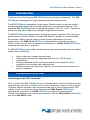
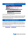
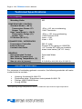
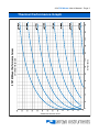
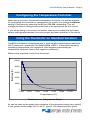
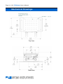
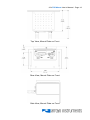
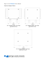
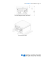
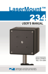
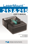
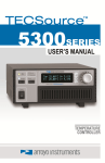
Page 2 · 274 TECMount User’s Manual Table of Contents Introduction ............................................................................................................. 3 Installation and Use ................................................................................................. 3 Mounting Plate ........................................................................................................ 4 Connector Pin-Outs................................................................................................. 5 EXT Input and SENSOR Switch .............................................................................. 5 Technical Specifications ......................................................................................... 6 Wetted Materials ...................................................................................................... 6 Thermal Performance Graph .................................................................................. 7 Pressure Drop vs Flow Graph ................................................................................. 8 Configuring the Temperature Controller ................................................................. 9 Using the Thermistor on Standard Versions .......................................................... 9 Using the RTD on 150°C Versions ........................................................................ 11 Operating at High Temperatures .......................................................................... 13 Mechanical Drawings ............................................................................................ 14 Warranty ................................................................................................................ 18 Service and Support ............................................................................................. 18 274 TECMount User’s Manual · Page 3 Introduction Thank you for choosing the 274 TECMount from Arroyo Instruments. The 274 TECMount is designed for high performance and long term use. The 274 TECMount integrates a high power Peltier cooler for precise control and substantial heating and cooling capacity for your powerful devices. The standard 274 TECMount has an operating range of -25°C to +85°C. Operation below the dew point requires a nitrogen-purged environment. The 274 TECMount requires water cooling for proper operation. For maximum performance, a chiller rated for at least 400 Watts or greater is recommended, but smaller chillers can be used for lower power applications. In most applications, the 5300-10-18 TECSource temperature controller is a good match for the mount, but for maximum performance, a 5400-15-28 TECSource temperature controller is required. The 274 TECMount also offers all the features you would expect from a modern diode fixture, including: Hard nickel over copper thermal plate. Designed to be quickly integrated with Arroyo’s TECSource instruments. Industry-standard D-sub connector and pin-outs allow for quick integration into existing laser applications. External sensor input for easy injection of on-board device sensor as sensor feedback. Installation and Use Connecting to the TEC Controller: First, connect the 274 TECMount to your temperature controller. Make sure the temperature controller’s current limit is set to a maximum value of no more than 16 Amps. Where possible, we recommend the use of Arroyo Instruments TEC cables. If you are using an Arroyo Instruments 5300 Series TECSource temperature controller, as 1262B TECSource cable is the recommend interconnect between the mount and controller. For the 5400 Series controllers, use the 1264-DB15 cable. Page 4 · 274 TECMount User’s Manual NOTE Arroyo Instruments offers TEC cables designed to connect directly between our TECSource products. If you use your own cables, ensure the connections are properly made between the instrument and the mount, and that proper grounding techniques are used. The pin-out of the connectors can be found later in this document. Connecting the water supply: The 274 comes with factory installed brass barbs suitable for 3/8” I.D. hose, but they can be replaced with any 1/8” NPT male fitting. It is recommended that when using the barbs, pipe clamps be used to secure the hose to the 274. NOTE Earth Grounding Considerations If your application requires that the cold plate be earth grounded, you should directly wire the cold plate to earth ground. When not using the 274 for prolonged periods of time, it is recommended that the water be drained from the unit and allowed to air dry. A burst of compressed air is also beneficial to blow out any residual water inside the unit. Mounting Plate The 274 TECMount has a bread board configuration with M3 holes on 10mm centers. Optional blank adapter plates are available in several sizes (3.2”, 4.2”, and 5.2” square) to allow for custom mounting patterns or larger mounting surfaces. See mechanical information below. 274 TECMount User’s Manual · Page 5 Connector Pin-Outs DB-15 Pin 1, 2 & 9 3, 4 & 10 7 & 14 8 & 15 11, 12 & 13 Description TE (+) TE (–) Thermistor or RTD / Sensor+ Thermistor or RTD / Sensor– FAN (+) DB-15 Connector Pin-Out Phoenix Pin Description 1 EXT (+) 2 EXT (–) Phoenix 2-Pin Connector Pin-Out Sensor Polarity and 4-Wire Connections While the thermistor and RTD inputs are not polarized, when using a 4-wire RTD connection from the mount, it is important to properly connect the polarity of the sense wires to the sensor. Pins 7 and 14 should be one polarity (+) and pins 8 and 15 should be the opposite polarity (–). If polarities are not matched, the instrument will indicate a sensor error. EXT Input and SENSOR Switch The 274 features a SENSOR switch to quickly switch between internal and external temperature sensors. With the SENSOR switch in the INT position, the internal thermistor embedded in the cold plate is used to provide the feedback for the temperature controller. With the SENSOR switch in the EXT position, the EXT+ and EXT- inputs on the Phoenix connector are connected to pins 7 & 14 Sensor+) and 8 & 15 (Sensor–). The 274 comes with one Phoenix 2-pin plug. Additional plugs can be ordered online at www.mouser.com or www.digikey.com, Phoenix part number 1803578. Page 6 · 274 TECMount User’s Manual Technical Specifications 274 TECMount COLD PLATE Mounting Holes TEMPERATURE CONTROL Standard Model (+85°C) Temperature Range (°C) Sensor Type High Temp Model (+150°C) Temperature Range (°C) Sensor Type TE Module (at 25°C)1 CONNECTORS / INTERFACES Temperature Controller External Sensor Coolant Inlet/Outlet GENERAL Recommended Coolant Max Water Pressure (psi) Max Housing Temperature (°C) Size (H x W x D) [in(mm)] M3 -25 to +85, non-condensing 10kΩ Thermistor -25 to +150, non-condensing 100Ω Platinum RTD Imax = 16A Vmax = 33V DB-15, male Phoenix 2-Pin (plug p/n 1803578) 1/8” Female NPT with pre-installed brass hose barbs (3/8” I.D. hose) Deionized Water 80 60 2.5 (63.5) x 4.8 (121.9) x 3.2 (81.3) Wetted Materials For purposes of evaluating galvanic corrosion, the following materials will make contact with the coolant: 1 Housing: Anodized AL 6061-T6 Dissipative plate: Electroless nickel plated AL 6061-T6 Fittings: UNS C36000 Brass O-ring: EPDM See Operating at High Temperatures, below, for additional requirements at high temperatures 274 TECMount User’s Manual · Page 7 160 140 120 100 80 60 40 20 0 0 20 40 60 80 100 120 140 160 180 200 220 240 260 Device Thermal Load (Watts) * Graph represents typical performance, and will vary by flow rate and other conditions. TEC Power (Watts) 20⁰C Water Temperature 274 TECMount Performance Curves 180 200 220 240 Thermal Performance Graph Page 8 · 274 TECMount User’s Manual Pressure Drop vs Flow Graph 274 TECMount Pressure Drop 20⁰C Water 12.0 10.0 Pressure Drop (psi) 8.0 6.0 4.0 2.0 0.0 0.0 0.5 1.0 1.5 2.0 2.5 3.0 Volume Flow Rate (gpm) * Graph represents typical performance, and will vary by flow rate and other conditions. 3.5 4.0 274 TECMount User’s Manual · Page 9 Configuring the Temperature Controller When using an Arroyo Instruments temperature controller, the easiest method for configuring the controller to operate with the mount is to change the Mount setting in the menu by selecting the 274 or 274-150, depending This will change the sensor settings and current limit to be appropriate for this mount. If you will be using a non-Arroyo controller, make sure to adjust the limits and sensor settings appropriately to ensure proper and safe operation of the mount. Using the Thermistor on Standard Versions The 274 LaserMount is equipped with a 10kΩ negative temperature coefficient (NTC) thermistor, specifically, the BetaTHERM 10K3A1. A thermistor works by translating temperature into resistance, with resistance decreasing as temperature increases (hence the ‘negative coefficient’). Below is the response curve of the thermistor: 50000 Resistance (Ω) 40000 30000 20000 10000 0 -10.00 10.00 30.00 50.00 70.00 90.00 110.00 Tem perature (°C) Resistance vs. Temperature Graph As can be seen by the graph, the resistance of the thermistor drops very quickly. In the typical control range (0°C to 40°C), typical 10K thermistors offer good Page 10 · 274 TECMount User’s Manual sensitivity to changes in temperature, and this is the range in which most 10K thermistors are typically used. 10K thermistors can be used at much higher temperatures, but will suffer poorer temperature stability performance because of the lower sensitivity. All Arroyo temperature controllers support operation using a 10μA or 100μA thermistor bias, which limits the upper control range to 450kΩ or 45kΩ, respectively. To minimize noise and maximize stability, you should select highest current while still allowing you full operation across your required temperature range. The typical setting is 100μA, but your application will determine the actual needs. The Steinhart-Hart Equation As can be seen from the temperature versus resistance graph above, resistance varies inversely with temperature in a non-linear fashion. This relationship can be accurately modeled by polynomial equations, and one such being the SteinhartHart equation: 1 A B * ln( R) C * ln( R) 3 T The coefficients for the BetaTHERM 10K3A1 thermistor are: A = 1.12924x10⁻³ B = 2.34108x10⁻⁴ C = 0.87755x10⁻⁷ These are the default coefficients for Arroyo Instruments temperature controllers, but can be changed in the Sensor menu, or by selecting the appropriate 274 mount from the Mount menu setting. 274 TECMount User’s Manual · Page 11 Using the RTD on 150°C Versions The 274 TECMount can optionally be configured for up to 150°C operation. To support this high temperature operation, a RTD sensor with a 0.00385 Ω / Ω / °C sensitivity is used. Like thermistors, RTDs also function by converting temperature into resistance, but unlike thermistors, RTDs increase in resistance as temperature increases. RTDs are also a fairly linear device, meaning they can be used across a much broader temperature control range. You can identify a 150°C configured 274 by its part number: a “-150” will be added to the end, for example, 274-150. According to IEC751, the resistance/temperature relationship is determined using one of two equations, dependent on the temperature or resistance value being measured. For resistances above the R0 value (resistance at 0°C, typically 100Ω, as is the case with the RTD used in the 274) of the RTD, the following equation is used: R R0 (1 AT BT 2 ) Below R0, an additional term is added to the equation: R R0 [1 AT BT 2 C (T 100)T 3 ] In both of these equations, R0 is the resistance of the RTD at 0°C, and A, B, and C are the coefficients as defined by IEC751, through regression analysis, or by using the Callendar-van Dusen method. Not all Arroyo Instruments temperature controllers support RTD operation. Check with the factory for the recommended controller. In most cases, the 530010-18 is the recommended controller for the 274, although lessor more powerful controllers may be used, depending on the thermal load capability required. For the Arroyo Instruments controllers that support RTD sensors, the default coefficients are not correct for this mount. They must be changed to use the 0.00385 Ω / Ω / °C curve, which has the following coefficients: A = 3.9080x10⁻³ B = -0.58019x10⁻⁶ C = -4.2735x10⁻¹² R0 = 100 Page 12 · 274 TECMount User’s Manual These coefficients can be changed in the Sensor menu, or by selecting the appropriate 274 mount from the Mount menu setting. 2-Wire versus 4-Wire Measurements One concern in using RTDs are their relatively low resistance (typically 100Ω at 0°C), and small Ω/°C. Because of these two factors, the resistance of the cable used to connect to the sensor can become a significant error in the sensor measurement. Most Arroyo Instruments controllers offer two RTD measurement modes: a conventional two wire measurement mode, which is subject to this error, and a four wire measurement mode that uses separate sensor and source lines to remotely sense the actual resistance of the RTD and eliminate the cable or connector resistances. When using 4-wire measurement mode, you must select ‘RTD (4-wire)’ as the sensor type, and then connect the Sensor+ and Remote Sensor+ at one side of the RTD, and Sensor– and Remote Sensor– to the other side of the RTD. Make these connections as close to the sensor as possible. The drawings below illustrate how 2-wire and 4-wire connections work. Note that 4-wire measurements require all four wires to be brought through the cable to the mount. The 1262 TECSource cable carries this connection through to the mount, but the 1260B cable does not. Temperature Controller Sensor+ Sensor– Mount RTD Sensor RTD 2-wire Measurement Temperature Controller Sensor+ Remote Sensor+ Remote Sensor– Sensor– RTD 4-wire Measurement Mount RTD Sensor 274 TECMount User’s Manual · Page 13 Operating at High Temperatures The 274-150 (150°C-capable version) has additional requirements that should be considered when operating in the upper temperature range: 1. 2. The voltage requirements of the TEC increase significantly when operating at the higher temperatures, so much so that the standard 5305 or 6300 Series controllers will be voltage limited when controlling the mount. To gain the maximum performance of the 274-150, the recommended controller is a 5300-10-18, which has an 10A / 18V output, or the 5400-15-28, which has a 15A / 28V output. Contact the factory for more details. If the mount is heating when at high temperatures, if possible, raise the water temperature. By lowering the temperature difference between the water temperature and the plate temperature, the TEC will not work as hard, and provide better plate uniformity as well as not requiring as much power to operate the TEC . Page 14 · 274 TECMount User’s Manual Mechanical Drawings Top View Rear View 274 TECMount User’s Manual · Page 15 Top View, Mount Plate on Front Rear View, Mount Plate on Front Side View, Mount Plate on Front Page 16 · 274 TECMount User’s Manual Optional Adapter Plates: 3.2” Adapter Plate, Top View (p/n AP-01-3.2) 4.2” Adapter Plate, Top View (p/n AP-01-4.2) 5.2” Adapter Plate, Top View (p/n AP-01-3.2) 274 TECMount User’s Manual · Page 17 274 with Adapter Plate, Side View 274 Isometric View Page 18 · 274 TECMount User’s Manual Warranty Arroyo Instruments warrants this product to be free from defects in material and workmanship under normal use and service for a period of one (1) year from date of shipment. It does not apply when the product has been misused, altered or damaged by accident or abnormal conditions of operation. If found to be defective during the warranty period, the product will either be repaired or replaced at Arroyo Instruments's option. THIS WARRANTY IS IN LIEU OF ALL OTHER WARRANTIES, EXPRESSED OR IMPLIED, INCLUDING IMPLIED WARRANTIES OF MERCHANTABILITY OR FITNESS FOR ANY PARTICULAR PURPOSE. ARROYO INSTRUMENTS SHALL NOT BE LIABLE FOR ANY INDIRECT, SPECIAL, OR CONSEQUENTIAL DAMAGES RESULTING FROM THE PURCHASE OR USE OF ITS PRODUCTS. Service and Support The 274 contains no user-serviceable parts. For service and support, contact your local distributor or Arroyo Instruments. Telephone: Facsimile: Email: Web: Address: +1 (805) 543-1302 +1 (805) 543-1303 [email protected] http://www.arroyoinstruments.com 624 Clarion Court San Luis Obispo, CA 93401 USA 274 TECMount User’s Manual · Page 19 NOTES: Page 20 · 274 TECMount User’s Manual Copyright © 2015, Arroyo Instruments. All Rights Reserved P/N 530-1042 Rev B