1
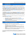
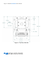
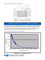
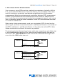
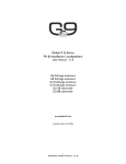
Page 2 · 262/264 LaserMount User’s Manual TableofContents Introduction ........................................................................... 3 Safety Terms and Symbols ................................................... 3 Installation and Use............................................................... 4 Connector Pin-Outs............................................................... 7 Technical Specifications ....................................................... 9 Mechanical Drawings .......................................................... 10 Using the Thermistor on Standard Versions....................... 16 Using the RTD on 150°C Versions ...................................... 18 Operating at High Temperatures ........................................ 20 Laser Diode Protection........................................................ 21 Warranty .............................................................................. 22 Maintenance and Service.................................................... 23 262/264 LaserMount User’s Manual · Page 3 Introduction Thank you for choosing the 262/264 LaserMount from Arroyo Instruments. The 262/264 LaserMount is designed for high performance and long term use. The 264 LaserMount integrates a large 120W Peltier cooler for precise control and substantial heating and cooling capacity for your powerful devices. The standard 264 LaserMount has an operating range of +15°C to +85°C, and the −150 version allows operation up to 150°C, covering a broad range of temperature control needs. The 262 LaserMount provides passive cooling with very low °C/Watt thermal rise. The 262/264 LaserMount comes standard with an integrated fan for additional cooling capacity. When used with the 5300 Series TECSource temperature controllers, no additional power supply is needed to power the fan, or use a standard external 12V DC power supply when connecting to other temperature controllers. The 262/264 LaserMount also offers all the features you would expect from a modern diode fixture, including: Hard nickel over 100% oxygen free copper thermal plate. Designed to be quickly integrated with Arroyo’s LaserSource and TECSource instruments. Industry-standard D-sub connectors and pin-outs allow for quick integration into existing laser applications. Safety Terms and Symbols The following safety-related terms are used in this manual: Warnings (noted by the WARNING heading) explain dangers that could result in physical injury or death; Cautions (noted by the CAUTION heading) explain conditions that could result in damage to the instrument, other equipment, or your device. Notes (noted by the NOTES heading) are not safety-related, and are intended simply to point out important information. If, at any time, any of the following conditions exist, or are suspected of existing, discontinue use of the unit until it can be inspected by qualified service personnel: Page 4 · 262/264 LaserMount User’s Manual Visible damage to the unit, including damage or stress caused during product shipment; Storage of the unit outside the standard storage temperature or humidity rating, or prolonged storage under harsh conditions; Failure to operate properly. If needed, contact your distributor or Arroyo Instruments for service or repair to ensure the safety of the product is maintained. Installation and Use The 262/264 LaserMount is an easy to use mount. It typically comes preconfigured for your device, so simply mount the device onto the plate using the holes provided, and make the electrical connections to the device. If you are using an Arroyo Instruments 5300 Series TECSource temperature controller, the fan supply is built directly into the TECSource. You will need to enable the fan supply in the TECSource menu – see the TECSource manual for additional details on how to do that. If you are using a third-party temperature controller, then you will need to provide a 12V DC power supply through the DB-15 connection. See the pinout below for the fan pin assignments. NOTE Earth Grounding Considerations The DB-9 or 9W4 and DB-15 connector shells are electrically connected to the housing and 8mm banana jack. Depending on the wiring of your cables and instruments, this may or may not provide earth grounding of the fixture. Make sure the cable shell is earth grounded on both ends of the cable, and that the instrument makes connection from its connector to earth ground. If in doubt, you can also use a grounding strap from the 8mm banana jack directly to earth ground. 262/264 LaserMount User’s Manual · Page 5 WARNING The mount is capable of producing high temperatures on the mounting plate, which can cause burns to skin or other objects that come in contact with the mounting plate. Connect to Laser Diode Driver and TEC Controller: Next, connect the 262/264 LaserMount to your laser diode driver and temperature controller. If using the 264, Make sure the temperature controller’s current limit is set to a maximum value of 7.4A. If using the 262 and connecting the temperature controller to your device, ensure that the maximum current for your device is properly set on the temperature controller. For 150°C versions, make sure to adjust the RTD coefficients to their proper values, or the temperature measurement and set point will not be correct. See Using the RTD on 150° Versions, below, for more information. The 262/264 LaserMount will be equipped with either a DB-9or 9W4 male connector for the laser. The DB-9 is used for lower power applications, usually no more than 10A, while the 9W4 supports up to 20A operation. Where possible, we recommend the use of Arroyo Instruments laser and TEC cables. Use p/n 1264 TECSource Cable for the temperature controller connection, and LaserSource cable as appropriate for your fixture. NOTE Arroyo Instruments offers Laser and TEC cables designed to connect directly between our LaserSource and TECSource products. If you use your own cables, ensure the connections are properly made between the instrument and the mount, and that proper grounding techniques are used. The pin-out of the connectors can be found later in this document. Page 6 · 262/264 LaserMount User’s Manual CAUTION Be sure you are properly ESD protected before handling your laser. For additional information, read the section titled “Laser Diode Protection” later in this manual. Mounting Plates The 262/264 LaserMounts are available with a variety of different mounting plates. The most common plate is the “BB” plate, which is a grid of mounting holes, much like an optical bread board (hence the “BB” desgination). There are two BB configurations: 264-BB – 2-56 holes on 0.25” centers 264M-BB – M2.5 holes on 6.25mm centers There is also a standard 264 Plate, detailed on page 14 below, which accepts a wide variety of device types. Because the specific model number of the 264 varies depending on the device termination requirements, please contact the factory for the appropriate 264 part number. To designate the connector type, add a “-DB9” or “-9W4” to the end for a DB-9 male connector or 9W4 male connector, respectively. For 150°C mounts, add a “-150” to the end of the part number. Additional configurations are available, including custom machined plates, contact the factory for details. 262/264 LaserMount User’s Manual · Page 7 Connector Pin-Outs 262/264 LaserMount Rear Connectors DB-9 Pin Description 1&2 No Connection 4&5 Laser Cathode 6 Photodiode (PD) Cathode 7 Photodiode (PD) Anode 8&9 Laser Anode Laser DB-9 Connector Pin-Out 9W4 Pin Description A1 Laser Anode A2 No Connection A3 Laser Cathode A4 No Connection Signal Pins No Connection Shell Earth Ground Laser 9W4 Connector Pin-Out Page 8 · 262/264 LaserMount User’s Manual DB-15 Pin Description 1, 2, & 9 TE (+) 3, 4, & 10 TE (–) 7 Thermistor or RTD (+) 8 Thermistor or RTD (–) 11 FAN (+) 12 FAN (–) 13 No connection 14 RTD Sense (+) 15 RTD Sense (–) TEC DB-15 Connector Pin-Out Sensor Polarity and 4-Wire Connections While the thermistor and RTD inputs are not polarized, when using a 4-wire RTD connection to the 264-150 mount, it is important to properly connect the polarity of the sense wires to the sensor. Pins 7 and 14 should be one polarity (+) and pins 8 and 15 should be the opposite polarity (–). If polarities are not matched, the instrument will indicate a sensor error. 262/264 LaserMount User’s Manual · Page 9 Technical Specifications FICATIONS 262/264 LaserMount LASER PACKAGE SUPPORTED Package TEMPERATURE CONTROL (264 only) Standard Version Temperature Range (°C) Sensor Type High Temperature Version Temperature Range (°C) Sensor Type TE Module Various high power devices +15 to +85 BetaTHERM 10K3A1IA 10kΩ Thermistor +15 to +150 100Ω Platinum RTD 0.00385 Ω / Ω / °C Imax = 7.4A Vmax = 16.4V INPUT CONNECTORS Laser Diode Temperature Controller DB-9, male or 9W4, male DB-15, male GENERAL Fan Size (H x W x D) [in(mm)] Mounting holes 12VDC, 210mA max 3.0 (76.2) x 4.5 (114.3) x 6.0 (152.4) Four holes for ¼-20 screws Page 10 · 262/264 LaserMount User’s Manual Mechanical Drawings Figure 1 - Top View of the 262 262/264 LaserMount User’s Manual · Page 11 Figure 2 - Detail View of the 262 Mounting Holes Page 12 · 262/264 LaserMount User’s Manual Figure 3 - Top View of the 264 262/264 LaserMount User’s Manual · Page 13 Figure 4 - Detail View of the 264 Mounting Holes Page 14 · 262/264 LaserMount User’s Manual Mounting Locations for Standard 264 Plate Butterfly 2-56 screws x 4 Lumics TO package 2-56 screws x 1 JDSU L3 2-56 screws x 4 SP package Alfalight AM6 package STAR LED JDSU L4, 4900 0-80 screws x 4 4-40 screws x 6 2-56 screws x 4 2-56 screws x 2 262/264 LaserMount User’s Manual · Page 15 Figure 5 - Rear View of 260 Series, DB9 Figure 6 - Rear View of 260 Series, 9W4 Page 16 · 262/264 LaserMount User’s Manual Figure 7 - Front View of 260 Series Using the Thermistor on Standard Versions The standard version of the 264 LaserMount is equipped with a 10kΩ negative temperature coefficient (NTC) thermistor, specifically, the BetaTHERM 10K3A1. A thermistor works by translating temperature into resistance, with resistance decreasing as temperature increases (hence the ‘negative coefficient’). Below is the response curve of the thermistor: 50000 Resistance (Ω) 40000 30000 20000 10000 0 -10.00 10.00 30.00 50.00 70.00 90.00 Tem perature (°C) Resistance vs. Temperature Graph 110.00 262/264 LaserMount User’s Manual · Page 17 As can be seen be the graph, the resistance of the thermistor drops very quickly. In the typical control range (0°C to 40°C), typical 10K thermistors offer good sensitivity to changes in temperature, and this is the range in which most 10K thermistors are typically used. 10K thermistors can be used at much higher temperatures, but will suffer poorer temperature stability performance because of the lower sensitivity. All Arroyo temperature controllers support operation using a 10μA or 100μA thermistor bias, which limits the upper control range to 450kΩ or 45kΩ, respectively. To minimize noise and maximize stability, you should select highest current while still allowing you full operation across your required temperature range. The typical setting is 100μA, but your application will determine the actual needs. The Steinhart-Hart Equation As can be seen from the temperature versus resistance graph above, resistance varies inversely with temperature in a non-linear fashion. This relationship can be accurately modeled by polynomial equations, and one such being the SteinhartHart equation: 1 A B * ln( R) C * ln( R) 3 T The coefficients for the BetaTHERM 10K3A1 thermistor are: A = 1.12924x10⁻³ B = 2.34108x10⁻⁴ C = 0.87755x10⁻⁷ These are the default coefficients for Arroyo Instruments temperature controllers. Page 18 · 262/264 LaserMount User’s Manual Using the RTD on 150°C Versions The 150°C version of the 264 LaserMount is equipped with a RTD sensor with a 0.00385 Ω / Ω / °C sensitivity. Like thermistors, RTDs also function by converting temperature into resistance, but unlike thermistors, RTDs increase in resistance as temperature increases. RTDs are also a fairly linear device, meaning they can be used across a much broader temperature control range. According to IEC751, the resistance/temperature relationship is determined using one of two equations, dependent on the temperature or resistance value being measured. For resistances above the R0 value (resistance at 0°C, typically 100Ω, as is the case with the RTD used in the 264) of the RTD, the following equation is used: R R0 (1 AT BT 2 ) Below R0, an additional term is added to the equation: R R0 [1 AT BT 2 C (T 100)T 3 ] In both of these equations, R0 is the resistance of the RTD at 0°C, and A, B, and C are the coefficients as defined by IEC751, through regression analysis, or by using the Callendar-van Dusen method. Not all Arroyo Instruments temperature controllers support RTD operation. Check with the factory for the recommended controller, as high temperature operation also has additional requirements for the controller (see Operating at High Temperatures, below). For the Arroyo Instruments controllers that support RTD sensors, the default coefficients are not correct for this mount. They must be changed to use the 0.00385 Ω / Ω / °C curve, which has the following coefficients: A = 3.9080x10⁻³ B = -0.58019x10⁻⁶ C = -4.2735x10⁻¹² R0 = 100 These coefficients can be changed in the Sensor menu. 262/264 LaserMount User’s Manual · Page 19 2-Wire versus 4-Wire Measurements One concern in using RTDs are their relatively low resistance (typically 100Ω at 0°C), and small Ω/°C. Because of these two factors, the resistance of the cable used to connect to the sensor can become a significant error in the sensor measurement. Most Arroyo Instruments controllers offer two RTD measurement modes: a conventional two wire measurement mode, which is subject to this error, and a four wire measurement mode that uses separate sensor and source lines to remotely sense the actual resistance of the RTD and eliminate the cable or connector resistances. When using 4-wire measurement mode, you must select ‘RTD (4-wire)’ as the sensor type, and then connect the Sensor+ and Remote Sensor+ at one side of the RTD, and Sensor– and Remote Sensor– to the other side of the RTD. Make these connections as close to the sensor as possible. The drawings below illustrate how 2-wire and 4-wire connections work. Note that 4-wire measurements require all four wires to be brought through the cable to the mount. The 1262 TECSource cable carries this connection through to the mount, but the 1260 cable does not. Temperature Controller Sensor+ Sensor– Mount RTD Sensor RTD 2-wire Measurement Temperature Controller Sensor+ Remote Sensor+ Remote Sensor– Sensor– RTD 4-wire Measurement Mount RTD Sensor Page 20 · 262/264 LaserMount User’s Manual Operating at High Temperatures The 264-150 (150°C-capable version) has additional requirements that should be considered when operating in the upper temperature range: 1. 2. The voltage requirements of the TEC increase significantly when operating at the higher temperatures, so much so that the standard 5305 or 6300 Series controllers will be voltage limited when controlling the mount. It is recommended that you purchase the 5300-04-15 controller, which has a 4A / 15V output, enough to provide the additional voltage needed by the mount, compared to the 5A / 12V outputs of the 5305 of 6300 Series controllers. Contact the factory for more details. Turn off the mount fan when operating significantly above ambient. By turning off the fan, you reduce the cooling efficiency on the heat sink, which is desirable when operating at high temperature, and will reduce the amount of TEC power required to reach and maintain the target temperature. However, you may still need the fan if you will be operating the mount under heavy thermal load such that it is cooling even at elevated temperatures. Note that the body of the heat sink will become warm, and could reach temperatures of up to 50°C. 262/264 LaserMount User’s Manual · Page 21 Laser Diode Protection Electrostatic discharge and current spikes can be a significant cause of damage to laser diodes, but when proper precautions are taken, these risks can be greatly reduced or eliminated. Arroyo Instruments’ controllers offer state-of-art laser diode protection, but no instrument can fully shield the laser from damage. Please take these considerations into account when operating your laser: 1. 2. 3. 4. 5. 6. Always set the current limit at or below the maximum current your laser can handle. This prevents the device from accidentally driving the current too high, either via the set point or from the modulation port. This also provides additional current limiting protection from ESD. Always work in an ESD safe operating environment, including the use of wrist straps, ESD grounded work surfaces and floors, and ESD-safe tools. Where the AC power to the laser driver to temperature controller may be noisy, use isolation transformers or uninterruptible power supplies that provide isolation. Make sure all cables are securely connected and fastening screws are screwed in tight. Do not route power cords or other cables in parallel with the laser or temperature controller cables, as coupling may occur between the cables and inject noise into the laser diode. While it is not possible to create a ground loop through the LaserSource because of it’s isolation of all inputs, it is possible when using other equipment. Ensure that any other equipment is properly isolated to avoid any ground loop problems. Page 22 · 262/264 LaserMount User’s Manual Warranty Arroyo Instruments warrants this product to be free from defects in material and workmanship under normal use and service for a period of one (1) year from date of shipment. It does not apply when the product has been misused, altered or damaged by accident or abnormal conditions of operation. If found to be defective during the warranty period, the product will either be repaired or replaced at Arroyo Instruments's option. THIS WARRANTY IS IN LIEU OF ALL OTHER WARRANTIES, EXPRESSED OR IMPLIED, INCLUDING IMPLIED WARRANTIES OF MERCHANTABILITY OR FITNESS FOR ANY PARTICULAR PURPOSE. ARROYO INSTRUMENTS SHALL NOT BE LIABLE FOR ANY INDIRECT, SPECIAL, OR CONSEQUENTIAL DAMAGES RESULTING FROM THE PURCHASE OR USE OF ITS PRODUCTS. 262/264 LaserMount User’s Manual · Page 23 Maintenance and Service Maintenance The ComboSource requires no regular maintenance other than product calibration. To clean the instrument, use cotton cloth that is only damp (not wet) with a light solution of soap and water. Fuses Under normal operation, you should never need to replace a fuse. However, if either fuse does blow, use only T 250V, 1A, IEC 60127-2 5x20mm metric fuses as replacements. If, after replacing the fuse, it continues to blow, immediately discontinue use of the instrument and contact service for support. Service Service and repair for the ComboSource can be obtained by contacting the distributor from where you purchased the instrument, or directly from Arroyo Instruments. A complete list of distributors is available on the Arroyo Instruments web site. You can contact Arroyo Instruments through one of these methods: By mail: By phone: By fax: By email: On the web: Arroyo Instruments 624 Clarion Court San Luis Obispo, CA 93401 USA +1 (805) 543-1302 +1 (805) 543-1303 [email protected] http://www.arroyoinstruments.com In all cases, Arroyo Instruments requires a return materials authorization (RMA) number. You must contact Arroyo Instruments and obtain an RMA number prior to returning your instrument, or the shipment may be rejected and sent back to you. Copyright © 2013, Arroyo Instruments. All Rights Reserved P/N 530-1013 Rev D