1
OPERATION MANUAL FVW-500HS Video Writer S/N 13090081 - Higher 3rd Edition - Rev.1 (Version 2.0.0.1) Edition / Version History Edition Revision Version Date 1 1.02008/12/17 2 1.0.12009/08/19 2 1 3 3 1 1.0.1- 2010/03/01 2.0.0 2010/05/09 2.0.0.1 2011/08/30 Description Where -Note on synchronization -GPI input/output supported Sec.2-2, 3-1-1 Sec.2-4, 4-2-7, 8-1 Sec.3-4, 8-1 Sec.5-4-1 -720p supported -Safety area marker range for 720p added -TV Standard and Genlock selection -System Adjust changed -Button order changed with keyboard and mouse -Video Writer GUI changed -A section for BIOS reset added -Important notice corrected -Specifications for video output, temperature and humid corrected -System setting modified -Resize button added -Still Capture and BG Capture buttons added -Right-double-click function for showing and hiding buttons on the screen added -Page function added -Multi Pointed Line tool added -Polygon tool added -Arrow tool added -Text tool added -Remove BG button added -Video in /out settings changed -Safety area marker changed -Handle setting added -Other settings added -An audio connector added Sec.3-4, 5-3-8 Sec.3-4 Sec.4-2-6, 5-2-4 Appendix Sec.3-2 Sec.8-1 Sec.3-4 Sec.4-2-5 Sec.4-2-6 Sec.4-2-12 Sec.4-2-13, 5-3-5 Sec.5-1-8 Sec.5-1-9 Sec.5-1-10 Sec.5-1-11 Sec.5-2-6 Sec.5-3-1 Sec.5-3-2 Sec.5-3-3 Sec.5-3-4-6, 5-3-4-7, 5-3-4-8 Sec. 2-2, 8-1, 8-2 Precautions Important Safety Warnings [Power] Operate unit only on the specified supply voltage. Caution Disconnect power cord by connector only. Do not pull on cable portion. Stop Do not place or drop heavy or sharp-edged objects on power cord. A damaged cord can cause fire or electrical shock hazards. Regularly check power cord for excessive wear or damage to avoid possible fire / electrical hazards. [Grounding] Ensure unit is properly grounded at all times to prevent electrical shock hazard. Caution Hazard Do not ground the unit to gas lines, units, or fixtures of an explosive or dangerous nature. Ensure power cord is firmly plugged into AC outlet. Caution [Operation] Hazard Hazard Do not operate unit in hazardous or potentially explosive atmospheres. Doing so could result in fire, explosion, or other dangerous results. Do not allow liquids, metal pieces, or other foreign materials to enter the unit. Doing so could result in fire, other hazards, or unit malfunction. If foreign material does enter the unit, turn power off and disconnect power cord immediately. Remove material and contact authorized service representative if damage has occurred. [Transportation] Caution Handle with care to avoid shocks in transit. Shocks may cause malfunction. When you need to transport the unit, use the original packing materials or alternate adequate packing. [Circuitry Access] Do not remove covers, panels, casing, or access circuitry with power applied to the unit! Turn power off and disconnect power cord prior to removal. Internal servicing / adjustment of unit should only be performed by qualified personnel. Stop Do not touch any parts / circuitry with a high heat factor. Capacitors can retain enough electric charge to cause mild to serious shock, even after power is disconnected. Capacitors associated with the power supply are especially hazardous. Avoid contact with any capacitors. Hazard Unit should not be operated or stored with cover, panels, and / or casing removed. Operating unit with circuitry exposed could result in electric shock / fire hazards or unit malfunction. [Potential Hazards] Caution If abnormal smells or noises are noticed coming from the unit, turn power off immediately and disconnect power cord to avoid potentially hazardous conditions. If problems similar to above occur, contact authorized service representative before attempting to again operate unit. [Rack Mount Brackets, Ground Terminal, and Rubber Feet] Caution To rack mount or ground the unit, or to install rubber feet, do not use screws or materials other than those supplied. Otherwise, it may cause damage to the internal circuits or components of the unit. If you remove the rubber feet attached on the unit, do not reinsert the screws securing the rubber feet. [Consumables] Caution The consumables used in unit must be replaced periodically. For further details on which parts are consumables and when they should be replaced, refer to the specifications at the end of the Operation Manual. Since the service life of the consumables varies greatly depending on the environment in which they are used, they should be replaced at an early date. For details on replacing the consumables, contact your dealer. Software License Agreement This Software License Agreement is a legally binding agreement between you (“User”) and FOR-A Company Limited (“Company”). The software, user manual and all other associated documentation (collectively, “Product”) are licensed, not sold, to the User. By installing and using the software, or by using a product of the Company in which the software is installed, User agrees to be bound by all terms and conditions of this agreement, as set forth below. 1. License Grant a. The Company grants User the license to use the Product in the manner specified in the user manual and other associated documentation. User may not use the Product in any manner other than specified. b. The Company only grants User the license to personally use the Product, and does not allow User to transfer the license to a third person or to enable a third person to use the Product by any other method. c. In principle, the software may only be used on a single computer or device. d. While the software may include various programs, they may not be unbundled and used as standalone programs. 2. Restrictions on Distribution, Duplication, Lease and Transfer User may not, without the Company’s prior permission, distribute via communication lines, or lease or transfer electronic copies of the Product, in whole or in part, nor attempt to do so. 3. Limitations of Guaranty The Company and its program licensors disclaim all legal warranties, express or implied, with respect to the Product. User must use the Product at own risk. In no event shall the Company and its program licensors be liable for any damage resulting from User’s use or inability to use the Product. 4. Provision of Upgrades and Updates Whenever the software is upgraded or updated, User may use the new version of the software by paying the amount separately specified by the Company. After upgrading the software, User may not use the earlier version without the Company’s prior permission. 5. Term of Validity of this Agreement This agreement shall be effective for a period of one year from the day User begins using the software. The same conditions of the agreement shall be extended for further one-year terms unless User or the Company expresses, at least one month prior to expiration of the agreement, the intent not to renew the agreement. 6. Termination of the Agreement a. The Company reserves the right to immediately terminate this agreement if User corresponds to either of the following circumstances. (1) User violates any terms of this agreement (2) User is unable or refuses to make the required payment b. User may terminate this agreement by written notice to the Company in the following circumstances, but may not seek a refund of the amount that User has already paid to the Company. (1) User waives the license (2) User destroys or loses the software package and prevents the Company from being able to confirm its existence c. After termination of this agreement, User may not use the Product in any way or form. 7. Ownership The Company and its program licensors retain all rights, including copyright and intellectual property rights, to the Product. User may not modify any program included in this software, nor disassemble, decompile, or reverse-engineer a program to analyze its source code. 8. Others This agreement will be governed by and construed in accordance with copyright laws and treaties in Japan and by laws and international treaties relating to intangible property rights. User must comply with all copyright laws and applicable laws and regulations when using the Product. 9. Jurisdiction Any dispute relating to the Agreement shall be subject to the jurisdiction of the Tokyo District Court. 10. Support If the Company discovers a flaw in the software or revises a program within one year after User receives the software, the Company will provide information regarding the flaw or revision or a revised program to User free of cost. * Microsoft Windows XP Embedded Operating System is a registered trademark of Microsoft Corporation. This application is using Open Source Computer Vision Library that is under the BDL license. IMPORTANT: READ BEFORE DOWNLOADING, COPYING, INSTALLING OR USING. By downloading, copying, installing or using the software you agree to this license. If you do not agree to this license, do not download, install, copy or use the software. Intel License Agreement For Open Source Computer Vision Library Copyright (C) 2000-2006, Intel Corporation, all rights reserved. Third party copyrights are property of their respective owners. Redistribution and use in source and binary forms, with or without modification, are permitted provided that the following conditions are met: * Redistribution's of source code must retain the above copyright notice, this list of conditions and the following disclaimer. * Redistribution's in binary form must reproduce the above copyright notice, this list of conditions and the following disclaimer in the documentation and/or other materials provided with the distribution. * The name of Intel Corporation may not be used to endorse or promote products derived from this software without specific prior written permission. This software is provided by the copyright holders and contributors "as is" and any express or implied warranties, including, but not limited to, the implied warranties of merchantability and fitness for a particular purpose are disclaimed. In no event shall the Intel Corporation or contributors be liable for any direct, indirect, incidental, special, exemplary, or consequential damages (including, but not limited to, procurement of substitute goods or services; loss of use, data, or profits; or business interruption) however caused and on any theory of liability, whether in contract, strict liability, or tort (including negligence or otherwise) arising in any way out of the use of this software, even if advised of the possibility of such damage. * All other trademarks and copyrights are property of their respective owners. All rights reserved. Upon Receipt Unpacking FVW-500HS units and their accessories are fully inspected and adjusted prior to shipment. Operation can be performed immediately upon completing all required connections and operational settings. Check your received items against the packing lists below. ITEM FVW-500HS AC Cord Rack Mount Brackets Rubber feet Operation Manual QTY 1 1 set 1 set 1 set 1 REMARKS One AC cord, and one AC cord retaining clip EIA standard type IMPORTANT Wait at least 10 seconds before turning back on the FVW-500HS after powering off. Check Check to ensure no damage has occurred during shipment. If damage has occurred, or items are missing, inform your supplier immediately. Rack Mounting The FVW-500HS can be mounted to EIA standard rack units. When rack mounting a unit, remove the rubber feet and use the accessory rack mount brackets (rack ears). Table of Contents 1. Prior to Starting ........................................................................................................................ 1 1-1. Welcome ........................................................................................................................... 1 1-2. FVW-500HS Overview ...................................................................................................... 1 1-3. Peripherals Needed for the System ................................................................................... 1 2. Panel Descriptions ................................................................................................................... 2 2-1. Front Panel ........................................................................................................................ 2 2-2. Rear Panel ........................................................................................................................ 3 2-3. Serial Interface .................................................................................................................. 4 2-4. Parallel Interface ............................................................................................................... 4 3. Setup ........................................................................................................................................ 7 3-1. Connection ........................................................................................................................ 7 3-1-1. Connection Example .................................................................................................. 7 3-1-2. How to Display Images ............................................................................................... 8 3-2. Powering On...................................................................................................................... 9 3-3. Installing Touch Panel Driver............................................................................................. 9 3-4. System Setting ................................................................................................................ 11 3-4-1. Selecting Video Format ............................................................................................ 12 3-4-2. Selecting Reference Signal ...................................................................................... 12 3-4-3. Selecting Genlock Signal ......................................................................................... 12 3-4-4. Adjusting Genlock Phases ....................................................................................... 13 3-4-5. Checking Lock Status............................................................................................... 13 4. Using Video Writer ................................................................................................................. 14 4-1. Starting and Exiting Video Writer ..................................................................................... 14 4-1-1. Starting Video Writer ................................................................................................ 14 4-1-2. Exiting Video Writer .................................................................................................. 14 4-2. Basic Operations ............................................................................................................. 15 4-2-1. Main Window ............................................................................................................ 15 4-2-2. Creating an Object ................................................................................................... 17 4-2-3. Erasing an Object ..................................................................................................... 19 4-2-4. Moving an Object ..................................................................................................... 19 4-2-5. Resizing an Object ................................................................................................... 20 4-2-6. Capturing a Still Image from Video Input .................................................................. 20 4-2-7. Modifying Properties ................................................................................................. 20 4-2-8. Selecting a Background Image................................................................................. 21 4-2-9. DSK On/Off .............................................................................................................. 21 4-2-10. Playing Movies ....................................................................................................... 22 4-2-11. Arranging Layer Order ............................................................................................ 23 4-2-12. Showing and Hiding Function Buttons and Setup Buttons ..................................... 24 4-2-13. Moving Between Pages .......................................................................................... 24 5. Setting Up Video Writer .......................................................................................................... 25 5-1. Properties ........................................................................................................................ 26 5-1-1. User Interfaces Used in Properties Dialog Boxes..................................................... 26 5-1-2. Line Properties ......................................................................................................... 27 5-1-3. Spotlight Properties .................................................................................................. 28 5-1-4. Circle Properties ....................................................................................................... 29 5-1-5. Numbering Properties ............................................................................................... 30 5-1-6. Object Properties ......................................................................................................31 5-1-7. Movie Properties .......................................................................................................32 5-1-8. Multi Pointed Line .....................................................................................................33 5-1-9. Polygon ..................................................................................................................... 34 5-1-10. Arrow ...................................................................................................................... 35 5-1-11. Text ......................................................................................................................... 36 5-1-12. Color Setting ........................................................................................................... 37 5-2. Menu ................................................................................................................................ 38 5-2-1. Adding a Draw Tool .................................................................................................. 39 5-2-2. Editing a Draw Tool................................................................................................... 39 5-2-3. Removing a Draw Tool ............................................................................................. 39 5-2-4. Changing Display Order of Draw Tools ..................................................................... 40 5-2-5. Adding a Background Button .................................................................................... 40 5-2-6. Removing a Background Button ............................................................................... 41 5-2-7. Saving a Video Writer File ........................................................................................ 41 5-2-8. Loading a Video Writer File ....................................................................................... 41 5-2-9. Custom Icon Settings ................................................................................................ 42 5-2-10. Calibration Settings .................................................................................................43 5-3. Option .............................................................................................................................. 44 5-3-1. Video In / Video Out Settings .................................................................................... 45 5-3-2. Showing Safety Area Markers .................................................................................. 47 5-3-3. Handle Settings.........................................................................................................49 5-3-4. Other Settings ........................................................................................................... 50 5-3-4-1. Showing Custom Icons ...................................................................................... 50 5-3-4-2. Undo Setting ......................................................................................................51 5-3-4-3. Dialog Mode Setting........................................................................................... 51 5-3-4-4. Mode for When Clicking an Object with a Draw Tool ......................................... 52 5-3-4-5. Invalid Area Setting ............................................................................................ 52 5-3-4-6. Keep Aspect ...................................................................................................... 52 5-3-4-7. Context Menu .................................................................................................... 53 5-3-4-8. Screen Keyboard ............................................................................................... 53 5-3-4-9. Language Setting ............................................................................................... 53 5-3-5. Page ......................................................................................................................... 54 6. Resetting to Defaults ............................................................................................................... 55 7. File Conversion Software (TGA/PNG to AVI) .......................................................................... 56 7-1. File Conversion ................................................................................................................ 56 7-2. Messages ........................................................................................................................ 57 8. Specifications and Dimensions ............................................................................................... 58 8-1. Unit Specifications ........................................................................................................... 58 8-2. External Dimensions ........................................................................................................ 59 Appendix. How to Reset BIOS .................................................................................................... 60 1. Opening BIOS Setup Menu ................................................................................................. 60 2. Setting Procedure ............................................................................................................... 61 1. Prior to Starting 1-1. Welcome Congratulations! By purchasing Video Writer you have entered the world of FOR-A and its many innovative products. Thank you for your patronage and we hope you will turn to FOR-A products again and again to satisfy your video and audio needs. FOR-A provides a wide range of products, from basic support units to complex system controllers, which have been increasingly joined by products for computer video based systems. Whatever your needs, talk to your FOR-A representative. We will do our best to be of continuing service to you. 1-2. FVW-500HS Overview FVW-500HS is a system for displaying lines, objects, images, and movies onto a video image in real time. Creating custom icons allows you to control the application via the touch screen. It is ideal for live broadcast environments, including weather news and sports. Full featured finger based Telestrator Draw and point in real-time over input video Straight line, free-hand, and pre-programmed graphic shape mode available Various types of lines, thickness, edge-width and colors Image file mapping and High-light function Move and Delete functions for drawn objects Dynamic and intuitive operation by touch panel option Freely assignable custom buttons for various tools 1-3. Peripherals Needed for the System The following peripherals are required depending on your system configuration. A VGA monitor or a touch panel monitor <VGA monitor> For viewing the image and operating the application, a VGA monitor and a connection cable are required. VGA monitor ―――(VGA cable)―――VGA connector of FVW-500HS rear panel <Touch panel monitor> Instead of a VGA monitor, a touch panel monitor and a connection cable are required if you wish to operate the application with your fingers. In that case, the touch panel driver installation is also necessary. See section 3-3, “Installing Touch Panel Driver” for details. Touch panel――(VGA cable)―――VGA connector of FVW-500HS rear panel Touch panel――(RS-232C cable)―― RS-232C connector of FVW-500HS rear panel Mouse If you are using a VGA monitor, a mouse is required. Plug the mouse into one of the USB ports (USB1-4) on the front or rear of FVW-500HS. Keyboard A keyboard is useful for entering text data. Plug the keyboard into one of the USB ports (USB1-4) on the front or rear of FVW-500HS. (An onscreen numeric keypad is also available.) 1 2. Panel Descriptions 2-1. Front Panel FVW-500HS VIDEO WRITER POWER ACT FAN POWER ON RESET USB 1 USB 2 OFF No. Name Description Lit green Power is applied to the unit. POWER The unit is powered off or no power cord is Unlit connected. Video Writer is running normally. Flashing It takes about 30 seconds for the ACT indicator to green start flashing after FVW-500HS is powered on. ACT Lit green Video Writer is not running or not running Unlit correctly. Unlit All cooling fans are operating normally. FAN One or more cooling fans failed. Turn off the Lit red power and replace the fans if necessary. Used to turn the unit on and off. Pressing "|" side turns the unit on. It takes about 5 seconds for the POWER indicator to light up after FVW-500HS is powered on. Wait at least 10 seconds and turn the power back on after powering off the FVW-500HS. 1 Status indicators 2 POWER switch 3 USB1 USB2 For connecting USB devices such as a keyboard, mouse, and other USB devices (USB2.0 compatible). 4 RESET If the POWER indicator does not light up green 5 seconds after the power switch is turned on, press the RESET switch (normally not used). NOTE If Video Writer is running normally, the ACT indicator flashes green. If the ACT indicator is lit or unlit, Video Writer is not running normally. If the application is not running, double-click the Video Writer shortcut icon to start the application. If the ACT indicator does not flash due to other reason than stated above, turn off the power switch of FVW-500HS and turn it on again. If the FAN indicator lights up red, it indicates fan failure. Turn off FVW-500HS and contact your dealer. 2 2-2. Rear Panel SER.NO. AC100-240V 50/60Hz IN GPI/ALARM OUT1 VIDEO VIDEO IN VIDEO 2 Name VIDEO IN OUT1 VIDEO OUT1 KEY OUT2 VIDEO OUT2 KEY 3 GENLOCK IN 4 GPI / ALARM 5 RS-232C 6 VGA 7 LAN1/2 8 USB3 USB4 9 AC IN 10 Ground terminal 11 Cooling fan 12 Audio out REMOTE KEY GENLOCK IN VGA No. 1 RS-232C OUT2 KEY LAN2 LAN1 USB4 USB3 Description For inputting an HD/SD SDI signal (BNC). Ref. 3-1-1 For outputting an HD/SD SDI signal (BNC). The VIDEO IN signal is bypassed to OUT1 VIDEO when FVW-500HS is powered off. 3-1-1 For inputting an external reference signal (B.B. or tri-level sync) to either of two connectors. The other connector is for loopthrough connection. It must be terminated with a 75 ohm terminating resistor when not used. For outputting power / fan alarm and GPI input/output. (15-pin D-sub female) For connecting a touch panel. (9-pin D-sub male) For connecting a VGA monitor. If a touch panel is used, this connector is used to connect with the VGA connector of the touch panel. For connecting to a computer Ethernet port. (100BASE-TX/1000BASE-T, RJ-45) (Not used.) For connecting USB devices such as a keyboard, mouse, and other USB devices (USB2.0 compatible). For connection to AC power source via accessory power cord. (100-240VAC 50/60Hz) For grounding unit to protect operators against static electricity and / or electrical shock. For cooling unit to prevent overheating. Do not block the fan intake at the right side of the unit with other equipment or objects. Audio connector. Compliant to Intel High Definition Audio, 2ch (Realtek ALC262) 3 3-1-1 3-4 5-3-1 2-4 2-3 3-1-1 3-1-1 3-1-1 2-3. Serial Interface RS-232C Pin Assignment Table (9-pin D-sub, male) Pin No. Signal Name In/Out Description 1 DCD In Data carrier detect 2 RXD In Receive data 3 TXD Out Transmit data 4 DTR Out Data terminal ready 5 GND Signal ground 6 DSR In Data set ready 7 RTS Out Request to send 8 CTS In Clear to send 9 RI In Ring indicator 2-4. Parallel Interface GPI / ALARM Pin Assignment Table (15-pin D-sub, female) Pin No. Signal Name Description 1 GND Signal ground 2 ALARM (POWER) Power alarm output, normally open relay (*1) 3 ALARM (FAN) Fan alarm output, normally open relay (*1) 4 N/C Not used 5 GPI IN3 Not used 6 GPI IN2 Not used 7 GPI IN1 GPI input (DSK ON/OFF) (*2) 8 +5V +5V DC output 9 COM Power alarm output, fan alarm output, common (*1) 10 N/C Not used 11 N/C Not used 12 GPI OUT3 Not used 13 GPI OUT2 Not used 14 GPI OUT1 GPI output (DSK ON/OFF tally) (*3) 15 GND Signal ground *The maximum current rating for each relay output: 0.5A, 30V DC (*1) See "Alarm Output Circuit" in page 5. (*2) See "GPI IN Circuit" in page 5. (*3) See "GPI OUT Circuit" in page 6. 4 Alarm Output Circuit Normally open relay circuit. Contact rating: 0.5A@30VDC Pin2: Pin3: Pin9: Power alarm output Fan alarm output the alarm common for both power alarm and fan alarm. When operating normally: An alarm pin and the common pin are open. When a malfunction occurs or An alarm pin and the common pin are closed. the power is off. Alarm output FVW-500HS side Relay contact Closed when a malfunction Relay contact occurs or the power is off. Max: 30V POW ALARM FAN ALARM COMMON GPI IN Cirsuit Pulse level trigger type. GPI IN pin and GND pin change the state from open to closed. Pulse width: 100msec or more, pulse interval: 100msec or more. GPI IN1 (Pin7) From open to closed position Toggles function On/Off (DSK ON/OFF) More than 100msec GPI IN pulse More than 100msec OPEN CLOSE More than 100msec GPI IN FVW-500HS side GPI IN1-3 GND 5 GPI OUT Circuit Open collector output. When using an external power source, its voltage should be 12V or less. The output current of each GPI OUT pin should be less than 20mA. GPI OUT1 (Pin14) When DSK is ON: When DSK is OFF: GPI OUT The pin and the ground pin are shorted. The pin and the ground pin are open. FVW-500HS side Max: 12V GPI OUT1-3 GND 6 3. Setup 3-1. Connection 3-1-1. Connection Example The figure below illustrates a connection example. FVW-500HS LINE VIDEO (HD/SD SDI) VIDEO VIDEO IN OUT1 To other device (The VIDEO IN signal is bypassed when FVW-500HS is powered off.) KEY VIDEO OUT2 Monitor out (Same video as OUT1 or not mixed with Line Video) KEY BB GENLOCK IN Loopthrough USB USB RS232C/ USB VGA Mouse Touch panel Keyboard VGA monitor USB ports are provided for connecting a keyboard and a mouse. If you are using a PS/2 mouse and PS/2 keyboard, use USB-PS2 adapters. The VIDEO IN signal is bypassed to OUT1 VIDEO when FVW-500HS is powered off. 7 3-1-2. How to Display Images FVW-500HS has three outputs: OUT1 (video signal and key signal), OUT2 (video signal and key signal), and VGA. Set the Video In, Video Out1, and Video Out2 settings in the Option dialog box (see section 5-3-1, “Video In / Video Out Settings”) and the background button in the main window (see section 4-2-8, “Selecting a Background Image”) to set whether to output the Video Writer image or whether to use the VIDEO IN image as the background. In addition, if both the Video Writer image and VIDEO IN image are output, use the DSK button in the main window to show and hide the Video Writer image (see section 4-2-9, “DSK On/Off”). If the settings are as below, the images are displayed as shown in the figure below. Background: Live DSK:On (button turns red) Video In: On (default) Video Out1: Mix (default) Video Out2: Mix (default) FVW-500HS DSK:Off VIDEO VIDEO IN OUT1 KEY VIDEO OUT2 KEY RS232C/ USB VGA To output VIDEO IN image to OUT1, OUT2, and VGA, click the Live background button in the main window. If Live is selected, the Video Writer objects (such as lines, spotlights, and circles etc…) and the VIDEO IN image are displayed. To use other image as the background, select the image with the background button. The same image is output to OUT1 and OUT2. Background: Live Background: soccor_bg1 8 3-2. Powering On After all connections are made, power on peripherals and then power on FVW-500HS. Video Writer is automatically started when Windows is started up. NOTE It takes about 5 seconds for the POWER indicator to light up after FVW-500HS is powered on. You can power off FVW-500HS without exiting Video Writer and shutting down Windows. To turn off the system, turn off FVW-500HS, and then turn off the monitor. NOTE Note that the C: drive of the FVW-500HS is write-protected. Please do not create folders and files to the C: drive or desktop. Instead, please save all folders and files to the D: drive. If files are save to the C: drive, the following errors may rarely occur. -Windows hangs up -The message “Error” is displayed while Video Writer is running or when changing the video format, and Video Writer is closed. If these happen, turn off the power and restart the FVW-500HS. 3-3. Installing Touch Panel Driver In order to use a touch panel, the touch panel driver must be installed. To allow powering off FVW-500HS without shutting down the computer, the C: drive is write-protected. You need to disable the write protection before installing the driver. Follow the steps below to disable the write protection, install the driver, and enable the write protection again. 1. Click the × button in the upper right corner of the window to exit Video Writer. 2. Double-click the ewf_disable.bat in D:\forawork to execute the batch file. 3. Command Prompt opens and shows the following messages. Press any key once on the keyboard. *************************************************************************** The write-protection (EWF) for the boot drive(C:) is set to disable. Execute the shutdown of Windows before turning off the power supply when write-protection is disabled. *************************************************************************** Press any key to continue . . . 4. The following messages appear. Check that Disable is shown in Boot Command and press any key once on the keyboard. Command Prompt closes. ** Disabling overlay Protected Volume Configuration Type RAM State ENABLED Boot Command DISABLE Param1 0 Param2 0 Persistent Data '' '' Volume ID XX XX XX XX XX XX XX XX XX XX XX XX XX XX XX XX Device Name ''\Device\HarddiskVolume1'' [C: ] Max Levels 1 Clump Size 512 Current Level 1 9 Memory used for data 8552960 bytes Memory used for mapping 12288 bytes *************************************************************************** The write-protection for the boot drive was set to disable. It is reflected in the next boot. Please restart the Windows. *************************************************************************** Press any key to continue . . . 6. Restart Windows from the Start menu. 7. After restarting, install the touch panel driver for your touch panel. Be sure to use the driver built for Window XP. 8. After installing the driver, double-click the ewf_enable.bat in D:\forawork to execute the batch file. 9. Command Prompt opens and shows the following messages. Press any key once on the keyboard. *************************************************************************** The write-protection (EWF) for the boot drive(C:) is set to enable. The any driver cannot install when write-protection is enabled. *************************************************************************** Press any key to continue . . . 10.The following messages appear. Check that Enable is shown in Boot Command and press any key once on the keyboard. Command Prompt closes. ** Enabling overlay Protected Volume Configuration Type RAM State DISABLED Boot Command ENABLE Param1 0 Param2 0 Persistent Data '' '' Volume ID XX XX XX XX XX XX XX XX XX XX XX XX XX XX XX XX Device Name ''\Device\HarddiskVolume1'' [C: ] Max Levels 1 Clump Size 512 Current Level N/A Memory used for data 0 bytes Memory used for mapping 0 bytes *************************************************************************** The write-protection for the boot drive was set to disable. It is reflected in the next boot. Please restart the Windows. *************************************************************************** Press any key to continue . . . 11.Shutdown Windows from the Start menu. 12.After shutting down, power off FVW-500HS. 13.Wait for about 10 seconds and turn on the power switch. Now the driver installation is complete. 10 3-4. System Setting This section describes how to select the video format and the reference signal, and adjust the genlock phases. 1. Click the Menu button in the main window. Click Menu 2. Click the Option button. Click Option 11 3. The screen for the video option settings appears. 3-4-1. Selecting Video Format 3-4-3. Selecting Genlock Signal 3-4-4. Adjusting Genlock Phases 3-4-5. Checking Lock Status 3-4-2. Selecting Reference Signal 3-4-1. Selecting Video Format To change video format, click a button in Video Format. It takes about several seconds to change the format. 3-4-2. Selecting Reference Signal To use a genlock signal, select Genlock in Lock Sorce. To use a video input signal, select VIDEO IN. 3-4-3. Selecting Genlock Signal To use a black burst signal, select BB (Black Burst) in Genlock. To use a tri-level sync signal, select TRI. This setting is necessary when Lock Source is set to Genlock. 12 3-4-4. Adjusting Genlock Phases Adjust the horizontal phase and the vertical phase of the genlock signal in H Phase and V Phase. These settings are necessary when Lock Source is set to Genlock. Setting range differs according to the video format. See section 5-3-1, “Video In / Video Out Settings” for details. 3-4-5. Checking Lock Status The status of whether or not the signal is properly synchronized with the signal selected in Lock Source is indicated. Lock: The signal is properly synchronized. Unlock: The external reference signal may not be present or the setting may not be properly made. Check procedures described in section 3-4-1 through 3-4-4. 13 4. Using Video Writer 4-1. Starting and Exiting Video Writer 4-1-1. Starting Video Writer On the desktop, double-click the shortcut to VideoWriter. NOTE Video Writer is automatically started when FVW-500HS is powered on. Normally you do not need to start the application manually. 4-1-2. Exiting Video Writer Click the × button in the upper right corner of the main window. Click the × button Main Window NOTE You can power off FVW-500HS without exiting Video Writer and shutting down Windows. 14 4-2. Basic Operations 4-2-1. Main Window Use the draw tools preset in advance to draw objects on the screen. See section 5, “Setting Up Video Writer” for details on properties settings. Draw Tools Function Buttons Setup Buttons Background Buttons Main Window Draw Tools Line Spotlight Circle Numbering Object Movie Multi Pointed Line Polygon Arrow Text Allows you to draw lines. Allows you to create spotlight effects. Allows you to create circles and ovals. Allows you to add numbering. Allows you to add images. Allows you to add movies. Allows you to draw multi pointed lines. Allows you to create polygons. Allows you to create arrows. Allows you to add texts. 4-2-2 Function Buttons DSK Clear All Erase Move Resize Play Still Capture BG Capture Remove BG Enables and disables to output the Video Writer image onto the OUT1 image (VIDEO/KEY). Clears all objects created using draw tools. Allows you to clear objects created using draw tools. Allows you to move objects created using draw tools. Allows you to resize objects created using draw tools. Plays movies added using the Movie tool. Captures a frame from a video input and saves it as an image file. Captures a frame from a video input, saves it as an image file, and creates a background button in the main window. Removes the selected background button and its background image from the main window. 15 4-2-9 4-2-3 4-2-3 4-2-4 4-2-5 4-2-10 4-2-6 4-2-6 5-2-6 Setup Buttons Modify Properties Menu Opens the Properties dialog box of the selected object. Opens the Properties dialog box of the selected draw tool. Opens the Menu dialog box. Background Buttons No background image is displayed. The VIDEO IN image is Live displayed. File name/ Displays a background image. Thumbnail Right-Click Menu Layer Arranges the layer order of objects. Right-Double-Clicking Show/hide Shows and hides the function buttons and the setup function buttons buttons in the main window. and setup buttons 4-2-7 5-1 5-2 4-2-8 4-2-8 4-2-11 4-2-12 Keyboard Move between pages Press the Page Up key on the keyboard to display the next page. Press the Page Down key to display the previous page. 4-2-13 Move between background images Press the left and right arrow keys (← →) on the keyboard to move between background images. 4-2-8 16 4-2-2. Creating an Object To draw an object preset in advance, select a draw tool on the main window and click or drag on the screen. The Spotlight and Movie objects cannot be placed at the same time. Spotlight, Numbering, Object, Movie, and Text Tools Dragging the mouse before releasing the mouse button allows you to move the object position. The object is placed where the mouse button is released. Spotlight Tool Numbering Tool Object Tool Movie Tool Text Tool 17 Line and Arrow Tools Where the mouse button is clicked will be the start point of the line, and where the mouse button is released will be the end point of the line. Line Tool Arrow Tool Circle Tool Where the mouse button is clicked will be the center point of the circle. If Draw Mode is set to Click in Circle Properties, clicking on the screen places a circle in the size specified in Size. If Draw Mode is set to Drag, dragging the mouse before releasing the mouse button allows you to resize the circle. Circle Tool Multi Pointed Line and Polygon Tools Clicking on the screen makes a handle (anchor point). Clicking again adds a new handle and draws a segment line or a side of the polygon. To create multiple lines or polygons, click the Multi Pointed Line or Polygon tool again, and then repeat the steps. Polygon Tool Multi Pointed Line Tool 18 4-2-3. Erasing an Object In the main window, click Erase and click an object or effect you wish to erase. For Multi Pointed Line and Polygon, clicking a handle erases just the handle, and clicking an object erases the whole object. Clicking Clear All clears all objects and effects (except the background image) from the window. Select Erase and click an object 4-2-4. Moving an Object In the main window, select Move and drag an object or effect you wish to move. For Multi Pointed Line and Polygon, dragging a handle moves just the handle, and dragging an object moves the whole object. Select Move and drag an object 19 4-2-5. Resizing an Object In the main window, select Resize and drag the edge of an object or effect you wish to resize. Select Resize and drag the edge of an object 4-2-6. Capturing a Still Image from Video Input Still Capture (or BG Capture) allows you to capture a frame from the video input when the button is clicked and save it as a still image file. A dialog box for specifying the file name appears. Specify the file name and directory and save the file. For touch screen, an on-screen keyboard can be used to specify the file name. To display the on-screen keyboard, set Screen Keyboard to Enable in Menu > Option > Other. In the same way as Still Capture, BG capture can also save a still image, and at the same time, it creates a background button of the captured image. If you wish to use the captured image as the background, BG Capture is convenient. 4-2-7. Modifying Properties In the main window, select Modify and click an object you wish to modify the properties. The Properties dialog box is displayed. In this dialog box, you can change the properties of the clicked object. The setting method is the same as Properties. See section 5-1, “Properties.” The Modify button is used to make settings of the clicked objects on the screen only. On the other hand, the Properties button is used to make settings of tool buttons. 20 4-2-8. Selecting a Background Image In the main window, check the file names and thumbnails displayed on the background buttons and click to select a desired background button. Or use the right and left arrow keys on the keyboard. The selected background button turns blue and the image is displayed in the window. If you do not wish to display any background image, click Live. NOTE You can also change the background button order. Click a desired button and drag and drop it to the desired position while pressing Ctrl on the keyboard. Click Live or desired Background button IMPORTANT To display the VIDEO IN image, click the Live background button. 4-2-9. DSK On/Off Selecting DSK in the main window turns the button to red and outputs the Video Writer image onto the VIDEO IN image when Video Out 1 in the Option dialog box is set to Mix (See section 5-3-1, "Video In / Video Out Settings "). Clicking DSK again while it is selected turns back the button to black and only the VIDEO IN image is shown in OUT1. IMPORTANT The DSK setting affects only to OUT1. The mixed image is always shown in OUT2. (See section 3-1-2, "How to Display Images.") Setting DSK to On or Off can be performed by using GPI IN function. (See section 2-4, "Parallel Interface" for details. The behavior of when DSK is turned on and off differs according to the DSK Mode setting. See section 5-3-1, "Video In / Video Out Settings" for details. 21 4-2-10. Playing Movies The movies placed onto the screen using the Movie tool appear differently depending on the Loop and Auto Reverse settings in the Movie Properties dialog box. See also section 5-1-7, “Movie Properties.” If Loop is set to On and Auto Reverse is set to Off: The movie is looped regardless of whether the Play button in the main window is selected or not. If both Loop and Auto Reverse are set to Off: To start the movie, click a movie on the screen while the Play button in the main window is selected. If Loop is set to Off and Auto Reverse is set to On: To start the movie, click a movie on the screen while the Play button in the main window is selected. Clicking other movie, which Loop is set to Off and Auto Reverse is set to On, plays the movie and plays the last played movie backward at the same time. Auto Reverse is not functional when Loop is set to On. 22 4-2-11. Arranging Layer Order To arrange the layer order of overlapped objects, follow the steps below. Right-click the object. Right-click the object you wish to arrange the layer order. A right-click menu is displayed. Refer to the table below and arrange the layer order. Top Up Down Bottom Example Brings the selected object to the front. Brings the selected object one layer forward. Sends the selected object one layer backward. Sends the selected object to the back. Right-click ① and choose Top from the right-click menu. ① is brought to the front. NOTE The Movie objects cannot be overlapped. The layer order can only be arranged for the still images added using the Object tool. The Movie objects are placed on top. 23 4-2-12. Showing and Hiding Function Buttons and Setup Buttons Right-double-click the drawing area to show or hide the draw tools, function buttons, and setup buttons. Right-double-click on the screen The buttons dissapear 4-2-13. Moving Between Pages Video Writer has 16 drawing pages. The first page is displayed the first time the application is started. The page number appears in Video Writer’s title bar. Press the Page Up key on the keyboard to display the next page. Press the Page Down key to display the previous page. Current Page Page Up Page Down Clicking the Clear All function button clears the objects in the current page only. The objects in the other pages are not cleared. Furthermore, naming and clearing pages, and switching pages is also possible. See section 5-3-5, “Page” for details. 24 5. Setting Up Video Writer To use Video Writer, the settings must be configured in advance in the Properties, Menu, Option, and Page dialog boxes. The Properties dialog boxes allow you to set the properties of draw tools. (See section 5-1, “Properties” for details.) The Menu dialog box allows you to add, edit, and remove draw tools, and make the background settings, and custom icon settings for touch screen use. Loading and saving Video Writer files can also be done in this dialog box. (See section 5-2, “Menu” for details.) The Option dialog box allows you to show and hide custom icons and safety area markers, and make the video format, reference signal, and other settings. (See section 5-3, “Option” for details.) The Page dialog box allows you to make the page settings. (See section 5-3-5, “Page” for details.) Properties Dialog Box Menu Dialog Box Option Dialog Box Page Configuration Dialog Box Dialog Boxes Properties Menu Option Page Select a draw tool in the main window and click the Properties button to open its Properties dialog box. The Properties dialog boxes allow you to make the properties settings of draw tools. Click the Menu button in the main window to open the Menu dialog box. This dialog box allows you to add, edit, and remove draw tools, and make background settings and calibration settings. The custom icon settings for touch screen use can also be done in this dialog box. Click the Option button in the Menu dialog box. This dialog box allows you to show and hide custom icons and safety area markers, and make the video format, undo, dialog mode, and other settings. Click the Page button in the Menu dialog box. This dialog box allows you to name and clear pages, and switch page numbers. 25 5-1. Properties To open a Properties dialog box, select a draw tool in the main window and click the Properties button. In the Properties dialog boxes, the properties settings of draw tools can be made. Icons of draw tools appear differently depending on the properties settings. NOTE A Properties dialog box cannot be displayed when a function such as Erase, Move, Resize, Play, or Modify is processed. Complete or cancel the current operation, select a draw tool in the main window and click the Properties button to open the Properties dialog box. 5-1-1. User Interfaces Used in Properties Dialog Boxes Each draw tool displayed in the main window has a separate Properties dialog box. Select button Color Arrow button Keypad Value text box Select button Left and right arrow buttons Value text box Color Keypad Allows you to select the style or type for the draw tool. The selected button turns blue. Allows you to change the property value by one step each time the button is clicked. Dragging the left arrow button to the left or the right arrow button to the right lets you change the value quickly. Allows you to enter the property value directly. Opens the Color dialog box. Select a color in Basic Colors or define a new color in Define Custom Colors. Opens the Keypad dialog box. This dialog box allows you to enter the value directly when using a touch screen. 26 5-1-2. Line Properties To display the Line Properties dialog box, select the Line tool and click the Properties button in the main window. In this dialog box, the line settings such as the style and color can be made. After setting all properties, click OK to apply the settings. Shape Item Line Style Arrow Type Draw Type Setting Range Solid, Dotted, Dashed None, Filled, Normal Freehand, Straight Description Allows you to select the line style. Allows you to select the arrow type. Allows you to select the draw type. Allows you to select whether to enable or disable Smoothing (*1) Enable, Disable Smoothing for freehand lines. (*1) Smoothing is only enabled when Draw Type is set to Freehand. If set to Straight, the Smoothing setting is ignored. Size Item Setting Range Description Line Width 5-200 (*2) Allows you to set the line width. Arrow Size 5-200 Allows you to set the arrow size. Edge Width 0-100 (*2) Allows you to set the edge width. Soft Edge 0-200 Allows you to set the softness of edge. Smoothness 1-100 Allows you to set smoothness of the freehand line. (*2) The sum of Line Width and both sides of Edge Width cannot exceed 200. Color Item Setting Range - R, G, B 0-255 Transparency 1-255 OK Cancel Description Clicking after selecting the Line or Edge button opens the Color dialog box, which allows you to set the color of Line and Edge separately. (See section 5-1-12, “Color Setting.”) Allows you to set the R, G, B values separately for Line and Edge after selecting the Line or Edge button. Allows you to set the transparency for Line and Edge. Applies the settings and closes the Properties dialog box. Closes the Properties dialog box without applying the settings. 27 5-1-3. Spotlight Properties To display the Spotlight Properties dialog box, select the Spotlight tool and click the Properties button in the main window. In this dialog box, the spotlight settings such as the size and softness can be made. After setting all properties, click OK to apply the settings. Shape Item Shape Type Setting Range Circle, Oval Description Allows you to select the shape type. Setting Range 5-500 0-200 Description Allows you to set the circle width. Allows you to set the softness of edge. Allows you to set the ratio of the height to the width of spotlight. This setting is effective only when Shape Type is set to Oval. Applies a fade-in effect to the spotlight. Set the duration in fields. Size Item Circle Width Soft Edge H/W Ratio 50-150 Transition 0-999 Color Item Setting Range - R, G, B 0-255 Transparency 1-255 OK Cancel Description Clicking opens the Color dialog box. The currently selected color is displayed. Allows you to set the R, G, B values for the mask color of spotlight. Allows you to set the transparency for the mask of spotlight. Applies the settings and closes the Properties dialog box. Closes the Properties dialog box without applying the settings. 28 5-1-4. Circle Properties To display the Circle Properties dialog box, select the Circle tool and click the Properties button in the main window. In this dialog box, the circle settings such as the style and color can be made. After setting all properties, click OK to apply the settings. Shape Item Shape Type Circle Style Setting Range Circle, Oval Solid, Wheel Draw Mode Click, Drag Description Allows you to select the shape type. Allows you to select the circle style. Allows you to place circles by clicking on the Click screen, in the size specified in Size. Allows you to resize circles by dragging, when it Drag first placed on the screen. Size Item Circle Width Edge Width Setting Range 5-500 (*1) 0-495 (*1) Description Allows you to set the circle width. Allows you to set the edge width. Allows you to set the line width when Circle Style is set to Line Width 1-200 (*2) Wheel. Soft Edge 0-200 Allows you to set the softness of edge. Allows you to set the ratio of the height to the width of circle. This setting is effective only when Shape Type is H/W Ratio 50-150 set to Oval. (*1) The sum of Circle Width and Edge Width cannot exceed 500. (*2) When Circle Kind is set to Wheel, the sum of Line Width and both sides of Edge Width cannot exceed 200. Color Item Setting Range - R, G, B 0-255 Transparency 1-255 OK Cancel Description Clicking after selecting the Fill or Edge button opens the Color dialog box, which allows you to set the color of Fill and Edge separately. (See section 5-1-12, “Color Setting.”) Allows you to set the R, G, B values separately for Fill and Edge after selecting the Fill or Edge button. Allows you to set the transparency for Fill and Edge. Applies the settings and closes the Properties dialog box. Closes the Properties dialog box without applying the settings. 29 5-1-5. Numbering Properties To display the Numbering Properties dialog box, select the Numbering tool and click the Properties button in the main window. In this dialog box, the numbering settings such as the style and color can be made. After setting all properties, click OK to apply the settings. Shape Item Shape Type Setting Range Circle, Oval Description Allows you to select the shape type. Size Item Circle Width Edge Width Soft Edge Setting Range 5-500 (*1) 0-495 (*1) 0-200 Description Allows you to set the circle width. Allows you to set the edge width. Allows you to set the softness of edge. Allows you to set the ratio of the height to the width of circle. This setting is effective only when Shape H/W Ratio 50-150 Type is set to Oval. (*1) The sum of Circle Width and Edge Width cannot exceed 500. Color Item Setting Range - R, G, B 0-255 Transparency 1-255 OK Cancel Description Clicking after selecting the Fill, Edge, or Text button opens the Color dialog box, which allows you to set the color of Fill, Edge, and Text separately. (See section 5-1-12, “Color Setting.”) Allows you to set the R, G, B values separately for Fill, Edge, and Text after selecting the Fill, Edge, or Text button. Allows you to set the transparency for Fill, Edge, and Text. Applies the settings and closes the Properties dialog box. Closes the Properties dialog box without applying the settings. 30 5-1-6. Object Properties To display the Object Properties dialog box, select the Object tool and click the Properties button in the main window. In this dialog box, you can set an image to an Object tool. The image size can also be set. After setting all properties, click OK to apply the settings. The supported file formats which can be specified are .tga, .png, .bmp, .jpg, .pbm, .sr, .tif, .exr, and .jp2. to the Object tool File Item Folder Files Description Allows you to specify the folder where the images are saved. Enter the full path in the text box or click the icon to open the Browse For Folder dialog box. The file names and thumbnails of the images saved in the specified folder are displayed in the Files list. The file names and thumbnails of the images in the folder specified in Folder are displayed. To set an image to an Object tool, select an image in this list. If you know the file name of the image you wish to select, you do not need to wait until the thumbnail is displayed. (The file names are displayed first, before the thumbnails are displayed.) Style Item Setting Range Enable, Disable Trail Properties Description Enables and disables the trail effect. When Trail is enabled, a path is drawn as you drag the object, when it is first placed. Allows you to set properties of the path when Trail is enabled. The setting method is the same as Line Properties. Size Item Object Width Object Height Original Size Constrain Proportions OK Cancel Setting Range 5-999 5-999 On, Off Description Allows you to set the object width. Allows you to set the object height. Returns the image to the original size. Changing the object width or height while Constrain Proportions is set to On constrains the proportions of the image. Applies the settings and closes the Properties dialog box. Closes the Properties dialog box without applying the settings. 31 5-1-7. Movie Properties To display the Movie Properties dialog box, select the Movie tool and click the Properties button in the main window. In this dialog box, you can set a movie to a Movie tool. The movie size and playback settings can also be made. After setting all properties, click OK to apply the settings. The supported file format which can be specified to the Movie tool is .avi. The images sequences such as tga images sequence and png images sequence can be converted to an .avi file using aviConv. See section. 7, “File Conversion Software (TGA/PNG to AVI)” for details. File Item Folder Files Description Allows you to specify the folder where the movies are saved. Enter the full path in the text box or click the icon to open the Browse For Folder dialog box. The file names and thumbnails of the movies saved in the specified folder are displayed in the Files list. The file names and thumbnails of the movies in the folder specified in Folder are displayed. To set a movie to a Movie tool, select a movie in this list. If you know the file name of the movie you wish to select, you do not need to wait until the thumbnail is displayed. (The file names are displayed first, before the thumbnails are displayed.) Size Item Movie Width Movie Height Original Size Constrain Proportions Playback Item Setting Range 5-999 5-999 On, Off Setting Range Loop On, Off Auto Reverse On, Off Description Allows you to set the movie width. Allows you to set the movie height. Returns the movie to the original size. Changing the movie width or height while Constrain Proportions is set to On constrains the proportions of the movie. Description If set to On, the movie is looped. If set to Off, the movie is not played until the Play button is clicked. If set to On, the last played movie of which Loop is set to Off is played backward when other movie is played. If Loop of the last played movie is set to On, it is not played backward. 32 Color Item Transparency Setting Range 1-255 Description Allows you to set the transparency of the movie. OK Cancel Applies the settings and closes the Properties dialog box. Closes the Properties dialog box without applying the settings. 5-1-8. Multi Pointed Line To display the Multi Pointed Line Properties dialog box, select the Multi Pointed Line tool and click Properties button in the main window. In this dialog box, the line settings such as the style, line width, and color can be made. After setting all properties, click OK to apply the settings. Shape Item Line Style Arrow Type Draw Type Setting Range Solid, Dotted, Dashed None, Filled, Normal Curve, Zigzag Description Allows you to select the line style. Allows you to select the arrow type. Allows you to select the draw type. Size Item Setting Range Description Line Width 2-200 (*1) Allows you to set the line width. Arrow Size 5-200 Allows you to set the arrow size. Edge Width 0-100 (*1) Allows you to set the edge width. Soft Edge 0-200 Allows you to set the softness of edge. (*1) The sum of Line Width and both sides of Edge Width cannot exceed 200. 33 Color Item Setting Range - R, G, B 0-255 Transparency 1-255 OK Cancel Description Clicking after selecting the Line or Edge button opens the Color dialog box, which allows you to set the color of Line and Edge separately. (See section 5-1-12, “Color Setting.”) Allows you to set the R, G, B values separately for Line and Edge after selecting the Line or Edge button. Allows you to set the transparency for Line and Edge. Applies the settings and closes the Properties dialog box. Closes the Properties dialog box without applying the settings. 5-1-9. Polygon To display the Polygon Properties dialog box, select the Polygon tool and click the Properties button in the main window. In this dialog box, the polygon settings such as the size and color can be made. After setting all properties, click OK to apply the settings. Size Item Soft Edge Setting Range 0-200 Description Allows you to set the softness of edge. Setting Range Description Clicking opens the Color dialog box, which allows you to set the color of polygons. (See section 5-1-12, “Color Setting.”) Allows you to set the R, G, B values separately for polygons. Allows you to set the transparency of the polygons. Color Item R, G, B 0-255 Transparency 1-255 OK Cancel Applies the settings and closes the Properties dialog box. Closes the Properties dialog box without applying the settings. 34 5-1-10. Arrow To display the Arrow Properties dialog box, select the Arrow tool and click the Properties button in the main window. In this dialog box, the arrow settings such as the style, line width, and color can be made. After setting all properties, click OK to apply the settings. Size Item Arrow Size Arrow Angle Setting Range 1-999 5-60 Description Allows you to set the arrow size. Allows you to set the sharpness of the arrowhead. Allows you to set the sharpness of the wings of the Sharpness 0-200 arrowhead. Pole Width 5-999 Allows you to set the width of the line. Allows you to scale only one end of a line. Setting to 100 makes both ends to the same width. Setting to 99 Tapering 0-200 or less narrows the opposite end of the arrowhead. Setting to 101 or more narrows the bottom of the arrowhead. Edge Width 0-100 (*1) Allows you to set the edge width. Soft Edge 0-200 Allows you to set the softness of edge. (*1) The sum of Line Width and both sides of Edge Width cannot exceed 200. Color Item Setting Range - R, G, B 0-255 Transparency 1-255 OK Cancel Description Clicking after selecting the Arrow or Edge button opens the Color dialog box, which allows you to set the color of Arrow and Edge separately. (See section 5-1-12, “Color Setting.”) Allows you to set the R, G, B values separately for Arrow and Edge after selecting the Arrow or Edge button. Allows you to set the transparency for Arrow and Edge. Applies the settings and closes the Properties dialog box. Closes the Properties dialog box without applying the settings. 35 5-1-11. Text To display the Text Properties dialog box, select the Text tool and click the Properties button in the main window. In this dialog box, the texts can be entered and the text settings such as the font, font weight, and alignment can be made. After setting all properties, click OK to apply the settings. Text Item String Font Weight Style Alignment Text Direction Setting Range Normal, Bold Normal, Italic Left, Center, Right Horizontal, Vertical Description Allows you to enter the text. Allows you to select the font. Allows you to select the font weight. Allows you to select the font style. Allows you to align the text. Allows you to set the text direction. Size Item Background Width Margin Character Width Character Height Setting Range 0-999 0-999 14-999 14-999 Description Allows you to set the width of the text background. Allows you to set the margin of the text background. Allows you to set the text width. Allows you to set the text height. Changing the text width or height while Constrain Constrain Proportions is set to On constrains the proportions On, Off Proportions of the text. Edge Width 0-100 (*1) Allows you to set the edge width. Soft Edge 0-200 Allows you to set the softness of edge. (*1) The sum of Line Width and both sides of Edge Width cannot exceed 200. 36 Color Item Setting Range - R, G, B 0-255 Transparency 1-255 Description Clicking after selecting the Text, Edge, or Bkgd button opens the Color dialog box, which allows you to set the color of Text, Edge and Bkgd separately. (See section 5-1-12, “Color Setting.”) Allows you to set the R, G, B values separately for Text, Edge or Bkgd after selecting the Text, Edge, or Bkgd button. Allows you to set the transparency for Text, Edge and Bkgd. Background Enable, Disable Enables and disables Text Background. (*1) (*1) If Background is set to Enable, the text is fit into the text background, regardless of the specified text width. OK Cancel Applies the settings and closes the Properties dialog box. Closes the Properties dialog box without applying the settings. 5-1-12. Color Setting To Select a Color To select a color for line, edge or other elements in Line Properties, Circle Properties and Numbering Properties dialogs, click the Color icon ( ) after selecting the Line, Edge, or other button to open the Color dialog box as shown below. Click on a desired cell to select a color. To Set a Custom Color Up to 5 custom colors can be set. To set a custom color, right-click on a cell, click the Define Custom Colors button and pick up a desired color for the cell. Right-click Custom color is set. Click 37 5-2. Menu To display the Menu dialog box, click the Menu button in the main window. In this dialog box, you can add, edit, and remove the Object tools, and make the background settings, calibration settings, and custom icon settings for touch screen use. Loading and saving Video Writer files can also be done in this dialog box. Menu Dialog Box Add to Toolbar Properties Remove Custom Icon Background Calibration Option Page Load Save Up/down arrow button OK Cancel Adds the draw tools selected in the Tools list to the main window. Opens the Properties dialog box of the draw tool selected in the Toolbar list. Removes the draw tools selected in the Toolbar list. Allows you to set an image for a custom icon. Allows you to specify an image to a background button. Allows you to make the calibration settings. Opens the Option dialog box. This dialog box allows you to make the video in and video out settings, size, undo, and dialog mode settings, and select whether to show or hide the custom icons and safety area markers. Opens the Page dialog box. This dialog box allows you to specify and clear page names. Loads the settings in a file saved using the Save button. Saves the current main window and current settings of draw tools and background buttons. The file extension is .vwf. Changes the display order of a draw tool selected in Toolbar. Applies the settings and closes the Properties dialog box. Closes the Properties dialog box without applying the settings. 38 5-2-1. Adding a Draw Tool To add a draw tool to the main window, select a draw tool in the Tools list in the Menu dialog box and click Add to Toolbar button. The draw tool is added to the Toolbar list. Clicking OK in the Menu dialog box closes the dialog box and adds the draw tool to the main window. Select a draw tool and click Add to Toolbar 5-2-2. Editing a Draw Tool To edit the properties of a draw tool displayed in the main window, select a draw tool in the Toolbar list in the Menu dialog box and click the Properties button. The Properties dialog box is displayed. See section 4-2-12, “Properties” for details. Clicking OK in the Menu dialog box closes the dialog box and applies the settings. Select a draw tool and click Properties 5-2-3. Removing a Draw Tool To remove a draw tool from the main window, select a draw tool in the Toolbar list in the Menu dialog box and click the Remove button. The draw tool is removed from the Toolbar list. Clicking OK closes the dialog box and removes the draw tool from the main window. Select a draw tool and click Remove 39 5-2-4. Changing Display Order of Draw Tools To change the display order of draw tools in the main window, select a draw tool in Toolbar list in the Menu dialog box and click △ or ▽ on the right. Moving a draw tool up in the list moves the draw tool left in the main window, and moving a draw tool down in the list moves the draw tool right in the main window. Clicking OK in the Menu dialog box closes the dialog box and changes the display order of draw tools. Select a draw tool and click △ or ▽ NOTE You can also change the draw tools order in the main window. Click a desired tool and drag and drop it to the desired position while pressing Ctrl on the keyboard. 5-2-5. Adding a Background Button To add a background button to the main window, click the Background button in the Menu dialog box. The Open dialog box is displayed. Specifying an image adds a button to the main window and the file name and thumbnail of the image are displayed on the button. The supported image file formats are .jpg, .bmp, .tga, and .png. Capturing an image of Live by clicking BG Capture adds a background image directly to a background button. 40 5-2-6. Removing a Background Button To remove a background button from the main window, select a background button and click the Remove BG button. You can also remove a background button by right-clicking a background button and selecting Remove from the right-click menu. Select a background button and click the Remove BG button 5-2-7. Saving a Video Writer File To save the current main window and current settings of draw tools and background buttons, click the Save button in the Menu dialog box. The Save As dialog box is displayed. Specify the file name and directory and click Save. Clicking OK in the Menu dialog box closes the dialog box and saves the current settings to a Video Writer file. The file extension is .vwf. 5-2-8. Loading a Video Writer File To load the settings saved in a file using the Save button in the Menu dialog box, click the Load button in the Menu dialog box. The Open dialog box is displayed. Select a file you wish to load and click Open. The progress status can be checked with the progress bar at the lower left of the dialog box. Clicking OK in the Menu dialog box closes the dialog box and loads the settings saved in a Video Writer file. 41 5-2-9. Custom Icon Settings For touch screen use, draw tools can be displayed as custom icons on the screen. In this dialog box, you can specify images for custom icons. To specify an image for a custom icon, select a draw tool in the Toolbar list in the Menu dialog box and click the Custom Icon button. The Open dialog box is displayed. Specifying an image using the Open dialog box adds the file name of the image to the Toolbar list. Clicking OK closes the dialog box and sets a custom icon image to a draw tool. The supported image file format is .tga and the supported size is 100 x 100 pixels. For details on showing custom icons on the screen, see section 5-3-4-1, “Showing Custom Icons.” Select a draw tool and click Custom Icon In the Menu dialog box, the image settings for the custom icons cannot be made for the Clear All, Erase, Move, Play, Modify, Properties, and Menu buttons. To set custom icon images to these buttons, overwrite images CIconClearAll.tga, CIconErase.tga, CIconMove.tga, CIconPlay.tga, CIconModify.tga, CIconProperties.tga, and CIconMenu.tga saved in the same directory as VideoWriter.exe. The supported image file format is .tga and the supported size is 100 x 100 pixels. For details on setting an image to an Object tool, see section 5-1-6, “Object Properties – File.” 42 5-2-10. Calibration Settings For the touch screen installed on the PC monitor Perform the calibration according to the specification of your touch screen. For details on calibration, see the manual of your touch screen. For the touch screen installed on the video monitor Open the Calibration dialog box by clicking the Calibration button. After clicking Start, perform the calibration according to the specification of your touch screen. Once the calibration is completed, click Finish. For details on calibration, see the manual of your touch screen. To use a touch screen installed on the video monitor, set to the full screen mode by double-clicking the right mouse button on the screen. 43 5-3. Option To display the Option dialog box, click the Menu button in the main window to display the Menu dialog box and click the Option button in the Menu dialog box. In this dialog box, you can make the video in and video out settings, size, undo, and dialog mode settings, and select whether to show or hide the custom icons and safety area markers. After all settings are done, click OK in the Option dialog box and click OK in the Menu dialog box to apply the settings. 44 5-3-1. Video In / Video Out Settings To display the Video settings, click Video in the Option dialog box. This screen allows you to make the video in and video out settings. Item Video Format Genlock Setting Range BB, TRI H Phase *1 V Phase *1 Video IN ON, OFF Video OUT1 Mix, VW Only Video OUT2 Mix, VW Only DSK Mode Normal, Spotlight Fading, Background On Lock Source Genlock, Video In Description Allows you to select the video format. Allows you to select the genlock signal type. Allows you to adjust the horizontal phase of the genlock signal. Allows you to adjust the vertical phase of the genlock signal. Allows you to select whether or not to input a video signal. Allows you to select whether to output the keyed image on top of the Video OUT1 signal or the keyed image only. Allows you to select whether to output the keyed image on top of the Video OUT2 signal or the keyed image only. Allows you to specify the behavior when the DSK button is turned on and off. Turns on and off the background still Normal image and drawn objects. Spotlight The spotlight effect fades in and out. Fading Turns on and off the drawn objects only. Background The background still image is displayed regardless of whether the DSK button is On turned on or off. Synchronizes with the Genlock IN signal. Please input a signal specified in Genlock Genlock (black burst or tri-level sync). Video IN Synchronizes with the Video In signal. (*1) The setting range differs according to the video format. See “Genlock Phase Setting Ranges” on the next page. Lock/Unlock Indicates whether or not the signal is synchronized with the signal specified in Lock Source. OK Cancel Applies the settings and closes the dialog box. Closes the dialog box without applying the settings. 45 Genlcok Phase Setting Ranges H Phase Video Format 1080/59.94i 1080/50i 720/59.94p 720/50p 525/60 625/50 V Phase Video Format 1080/59.94i 1080/50i 720/59.94p 720/50p 525/60 625/50 Setting Range -1100 to +1099 (-14.83 μs to +14.81 μs) -1320 to +1319 (-17.80 μs to +17.78 μs) -825 to +824 (-11.12 μs to +11.11 μs) -990 to +989 (-13.34 μs to +13.32 μs) -858 to +857 (-31.78 μs to +31.74 μs) -864 to +863 (-32.00 μs to +31.96 μs) Per Increment 1 (13.48 ns) 1 (13.47 ns) 1 (13.48 ns) 1 (13.47 ns) 1 (37.04 ns) 1 (37.04 ns) Default Setting Range -562 lines to +562 lines (-16.68 ms to +16.68 ms) -562 lines to +562 lines (-16.68 ms to +16.68 ms) -375 lines to +374 lines (-8.34 ms to +8.32 ms) -375 lines to +374 lines (-10.00 ms to +9.97 ms) -262 lines to +262 lines (-16.68 ms to +16.68 ms) -312 lines to +312 lines (-16.68 ms to +16.68 ms) Per Increment 1 lines (29.66 μs) 1 lines (35.59 μs) 1 lines (22.24 μs) 1 lines (26.67 μs) 1 lines (63.56 μs) 1 lines (64.0 μs) Default 46 0 0 0 0 0 0 0 0 0 0 0 0 5-3-2. Showing Safety Area Markers To display the Area Marker settings, select Area Marker in the Option dialog box. This screen allows you to make the safety area marker settings. Area Marker Item Show/Hide Marker Selection New Setting Range Show, Hide Description Allows you to show or hide safety area markers. Allows you to select a safety area marker you wish to 1-9 (*1) change the settings. Allows you to add area markers to Marker Selection. Allows you to remove the area marker selected in Marker Remove Selection. (*1) Two area markers are added with the default setting. 47 Size Item Setting Range Side Cut Marker Size 100%, 95%, 90%, 85% Left Right Top 0-1920 0-1920 0-1080 Bottom 0-1080 Line Width 1-100 Description Allows you to turns on and off Side Cut. The button appears red when turned on. The preset buttons for specifying the size of the area marker. The drawing area is defined as 100% when turned off, and the 4:3 area is defined as 100% when turned on. The Side Cut setting needs to be set before specifying Marker Size. Allows you to set the left edge of the safety area marker. Allows you to set the right edge of the safety area marker. Allows you to set the top edge of the safety area marker. Allows you to set the bottom edge of the safety area marker. Allows you to set the width of the border. Color Item Setting Range - R, G, B 0-255 Transparency 1-255 OK Cancel Description Clicking opens the Color dialog box, which allows you to set the color of safety area markers. (See section 5-1-12, “Color Setting.”) Allows you to set the R, G, B values separately for safety area markers. Allows you to set the transparency for safety area markers. Applies the settings and closes the dialog box. Closes the dialog box without applying the settings. 48 5-3-3. Handle Settings To display the Handle settings, select Handle in the Option dialog box. This screen allows you to make settings for handles displayed for Multi Pointed Line and Polygon. Size Item Setting Range Handle Size (SD) 1-999 Handle Size (HD) 1-999 Description Allows you to set the handle size for the SD video format. Allows you to set the handle size for the HD video format. Color Item Setting Range - R, G, B 0-255 Transparency 1-255 OK Cancel Description Clicking opens the Color dialog box, which allows you to set the color of handles. (See section 5-1-12, “Color Setting.”) Allows you to set the R, G, B values separately for handles. Allows you to set the transparency for handles. Applies the settings and closes the dialog box. Closes the dialog box without applying the settings. Changes are not applied to the handles that are already placed to the drawing area. Please make settings before creating objects. 49 5-3-4. Other Settings To display the Other settings, select Other in the Option dialog box. This screen allows you to make settings such as the custom icon settings and undo setting. 5-3-4-1. Showing Custom Icons To show custom icons on the screen, open the Option dialog box and set Show/Hide to Show and select the display position in Layout. The custom icons can be displayed at the left, right, top, or bottom of the screen. Selecting Top and Show displays the custom icons at the top of the screen Custom icons The custom icons can also be turned on and off by clicking any one of the four corners of the screen. If Layout is set to None, clicking a corner does not display the custom icons regardless of whether Show/Hide is set to Show or not. 50 5-3-4-2. Undo Setting To assign the undo function to one of the four corners of the screen, select Upper Left, Upper Right, Lower Left or Lower Right in Undo in the Option dialog box. After the setting is done, click the specified corner of the screen to undo the last action. Although the standard keyboard shortcut ( Ctrl + Z ) is also available, assigning the undo function to the screen allows you to use it on the touch screen. Click this area while Undo is set to Upper Right to undo the last action 5-3-4-3. Dialog Mode Setting Whether to display dialog boxes such as the Properties dialog boxes and Menu dialog box on both the SDI monitor and VGA monitor or the VGA monitor only can be selected. To display dialog boxes on both the SDI monitor and VGA monitor, set Dialog Mode to Both in the Option dialog box. To display dialog boxes on the VGA monitor only, set to VGA Only. Select Both or VGA Only 51 5-3-4-4. Mode for When Clicking an Object with a Draw Tool The behavior when clicking an object on the screen while a draw tool is selected can be specified. To create a new object when an object on the screen is clicked with a draw tool, set Add onto Obj to Create in the Option dialog box. To move the object on the screen when it is clicked with a draw tool, set Add onto Obj to Move. Select Create or Move 5-3-4-5. Invalid Area Setting The invalid area, which you cannot place objects can be set. This is used to avoid placing unnecessary images by accidentally clicking the screen. The invalid area is 60 pixels from the edge of the screen. To turn on the invalid area, set Invalid Area to On in the Option dialog box. Set to On to turn on the invalid area. 5-3-4-6. Keep Aspect Keep Aspect allows you to set the aspect ratio setting for the VGA output. Setting Keep Aspect to ON maintains the aspect ratio regardless of the window size. For HD, the aspect ratio is constrained to 4:3. For SD, the aspect ratio is constrained to 4:3 if Squeeze is set to Off, and it is constrained to 16:9 if Squeeze is set to ON. Set to On to maintain the aspect ratio. 52 5-3-4-7. Context Menu Context Menu allows you to enable and disable right-click menus (context menus) shown when the drawing area is right-clicked. Set to Enable to show the right-click menu when the drawing area is right-clicked. 5-3-4-8. Screen Keyboard Allows you to enable and disable the on-screen keyboard for touch screen use, for entering texts for the file names or the Text tool. On-Screen Keyboard Set to Enable to show the on-screen keyboard. If set to Disable, the on-screen keyboard does not appear for entering texts for the file names and the Text tool. 5-3-4-9. Language Setting The Language setting is only available in Japanese version. 53 5-3-5. Page To display the Page Configuration dialog box, click the Menu button in the main window to display the Menu dialog box and click the Page button in the Menu dialog box. In this dialog box, you can specify a page name for each page. Press the Page Up and Page Down keys on the keyboard to move between pages. Up to 16 pages can be set. After making all settings, click OK in the Page Configuration dialog box, and then click OK again in the Menu dialog box to apply the settings. Page Item Name Apply Pages Item Pages Description Allows you to enter the page name after selecting a page in Pages. Allows you to apply the name entered in Name. Clear All Description Allows you to select a page by clicking. Allows you to change the page number of the page selected in Pages. Allows you to switch the selected page with the Up arrow button △ previous page. Allows you to switch the selected page with the Down arrow button ▽ next page. Clears page names and drawn objects of all pages. OK Cancel Applies the settings and closes the dialog box. Closes the dialog box without applying the settings. Up and down arrow buttons 54 6. Resetting to Defaults The settings of FVW-500HS are saved as below. File Settings How to Save and Load Settings VideoWriter.ini Properties settings of draw tools Background button settings Option settings Safety area marker settings Video format setting External reference input setting Click OK in the Properties dialog boxes. The settings are kept until the next time the application is started. VideoWriter file (vwf file) Current image on the screen Properties settings of draw tools Background button settings Save and load the .vwf files (See 5-2-7 and 5-2-8). To reset the above settings to defaults, follow the steps below. 1. In Video Writer, click the × button in the upper right corner of the main window to close the application. 2. To execute a batch file, double-click Default.bat located in C:\VideoWriter\ 3. The command prompt is launched automatically. Once the command prompt finishes its process, the settings are reset. 4. The settings are reset to defaults the next time you run Video Writer. 55 7. File Conversion Software (TGA/PNG to AVI) aviConv allows you to convert a tga or png sequence to an uncompressed 32bit avi file. Allows you to convert to an uncompressed 32bit avi file Resizing function Sequences in 32bit tga and png format are supported NOTE Although a sequence in 24bit format can also be specified, the alpha channel will be white when Bit Depth is set to 32bit. 7-1. File Conversion 1. Double-click aviConv icon on the desktop to start aviConv 2. In Source Folder, specify the folder where the original files exist. Enter the folder path directly in the text box, or click the icon to open the Browse for Folder dialog box to specify the folder. 3. In Destination Folder, specify the file name and destination folder to save the avi file. Enter the folder path directly in the text box, or click the icon to open the Save As dialog box to specify the folder. 4. In Width x Height, specify the resolution of the avi file. Click the Original Size button to keep the resolution to the same size as the original files. 5. In Bit Depth, select the bit depth from 32bit (with an alpha channel) or 24bit (without an alpha channel). 6. Click the Convert button to start conversion. The progress status can be checked with the progress bar to the left of the Convert button. 7. Click the × button in the upper right corner of the window to exit aviConv. 56 7-2. Messages After the conversion, one of the following messages is displayed. If an error message is displayed, check the file format and conversion settings. Your files have been converted successfully. Displayed after the conversion is successfully completed. Conversion failed! The file in the destination folder may be locked, or the setting in the Source Folder or Destination Folder may not have been properly made. An error occurred while attempting to obtain the video size. The setting in the Source Folder may not have been properly made. 57 8. Specifications and Dimensions 8-1. Unit Specifications TV Standards HD SDI 1080/59.94i, 1080/50i, 720/59.94p, 720/50p SD SDI 525/60, 625/50 Signal Processing 4:2:2:4 digital component Quantizing 10-bit Video Inputs HD: 1.485/1.001Gbps or SD: 270Mbps 75Ω, BNC, 1 input Video Outputs HD: 1.485/1.001Gbps or SD: 270Mbps 75Ω, BNC, 4 outputs (2 outputs for key fill signal, and other 2 for key source signal. VIDEO IN input is bypassed through OUT1 VIDEO output when the unit is powered off.) Genlock Input BB: NTSC 0.429V(p-p) / PAL 0.45V(p-p) or Tri-level Sync: 0.6V(p-p) 75Ω (termination required) or loopthrough, BNC, 1 input Input Lock ±0.5H relative to genlock signal phase I/O Delay 1 frame when the phase of input video is same as that of genlock. Interface RS232C 9-pin D-sub, male, 1 port VGA Output resolution SXGA (1280x1024),15-pin mini D-sub (female) x 1 USB 2.0 (High Speed), Series-A type connector, 4 ports (2 ports in the front panel and 2 ports in the rear panel) LAN1 Not used LAN2 Not used REMOTE Not used RS232C 9-pin D-sub (male) x1 GPI/ALARM 15-pin D-sub (female) x1 ALARM: power and fan alarm (Relay make contact output) GPI: 1-input/1-output (Input: contact closure, Ouput: open collector) Audio out 3.5 mm stereo mini jack x 1 Temperature 0°C - 40°C Humidity 20% - 80% (no condensation) Power AC100V - 240V Consumption 110VA (113W) at 100VAC 110VA (96W) at 200VAC Dimensions 430 (W) x 44 (H) x 500 (D) mm, EIA 1RU Weight 9 kg ±10%, 50/60Hz 58 Consumables (if used 24 hours a day at normal temperature) Cooling fans: Power: Battery: Replace every 3 years. Replace every 5 years Replace every 5 years. 8-2. External Dimensions (All dimensions in mm.) VGA AC100-240V 50/60Hz IN LAN2 VIDEO OUT1 KEY VIDEO OUT2 USB4 USB3 KEY 2.3 500 GPI/ALARM VIDEO W RITER FAN POWER ON RESET USB 1 USB 2 OFF 430 462 480 59 44 LAN1 GENLOCK IN VIDEO IN SER.NO. FVW-500HS POWER ACT RS-232C REMOTE Appendix. How to Reset BIOS This appendix explains how to reset the BIOS. Please follow the procedure below in case you need to reset the BIOS due to the battery failure or such reason. 1. Opening BIOS Setup Menu 1. Connect a PC monitor, a keyboard, and a mouse to the FVW-500HS and turn on the unit. 2. The screen appears as below. Press the F1 key. 3. The BIOS SETUP UTILITY is opened. Menu item Submenu 60 On the BIOS SETUP UTILITY screen, set the values for the menus as shown below. The detailed procedure is given in the following section. Item (1) Menu bar Main (2) Advanced (3) Boot (4) Chipset Menu item System Time System Date Floppy Configuration Boot Settings Configuration Boot Device Priority South Bridge Chipset Configuration Submenu Floppy A Floppy B Wait For ‘F1’If Error 1st Boot Device Restore on AC Power Loss Value Current time Current date Disabled Disabled Disabled Hard Disk Power On 2. Setting Procedure (1) Set the current date and time in the Main menu provided on the menu bar. (a) On the menu bar, select Main using the right and left arrow keys. Main menu screen (b) Set the system time. Select System Time using the right and left arrow keys. Enter the current time using the numeric keys. Press Enter to confirm the change and move the cursor to the next item on hour, minute, and second. (c) Set the current date. Select System Date using the right and left arrow keys. Enter the current time using the numeric keys. Press Enter to confirm the change and move the cursor to the next item on month, day, and year. 61 (2) Set the Floppy Configuration parameters in the Advanced menu on the menu bar. Advanced menu screen (a) On the menu bar, select Advanced using the right and left arrow keys. (b) Select Floppy Configuration using the up and down arrow keys, and press Enter. The Floppy Configuration menu will be displayed. Floppy Configuration menu (c) Disable Floppy A and Floppy B. Select Floppy A or Floppy B using the up and down arrow keys, and press Enter. The Options window as shown below appears. Select Disabled and press Enter. 62 * After you finish the setting, verify that the value in the square brackets opposite the item is set to Disabled. The Esc key on the keyboard allows you to return to the previous screen. (3) Set the Boot Settings Configuration parameters and Boot Device Priority in the Boot menu on the menu bar. Boot Menu Screen (a) Select Boot on the menu bar using the right and left arrow keys. (b) Set the Boot Settings Configuration parameters. Select Boot Settings Configuration using the up and down arrow keys, and press Enter. The Boot Settings Configuration menu will be displayed. 63 Boot Settings Configuration menu (c) Set Wait For ‘F1’ If Error to Disabled. Select Wait For ‘F1’ If Error using the up and down arrow keys. Press Enter. The Options window as shown below appears. Select Disabled, and press Enter. * After you finish the setting, verify that the value in the square brackets opposite the item is set to Disabled. The Esc key on the keyboard allows you to return to the previous screen. 64 (d) Set the Boot Device Priority. Select Boot Device Priority using the up and down arrow keys, and press Enter. The Boot Device Priority menu will be displayed. Boot Device Priority menu (e) Set 1st Boot Device to HDD: xxxxxxx. Select 1st Boot Device using the up and down arrow keys. Press Enter. The Options window as shown below appears. Select HDD: xxxxxxx, and press Enter. 65 * After you finish the setting, verify that the value in the square brackets opposite the item is set to HDD: xxxxxxx. The Esc key on the keyboard allows you to return to the previous screen. (4) Set the South Bridge Chipset Configuration parameters in the Chipset menu on the menu bar. Chipset menu screen (a) Select Chipset menu on the menu bar using the right and left arrow keys. (b) Select South Bridge Configuration using the up and down arrow keys, and press Enter. The South Bridge Chipset Configuration menu will be displayed. 66 South Bridge Chipset Configuration menu (c) Set Restore on AC Power Loss to Power On. Select Restore on AC Power Loss using the up and down arrow keys. Press Enter. The Options window as shown below appears. Select Power On, and press Enter. * After you finish the setting, verify that the value in the square brackets opposite the item is set to Power On. The Esc key on the keyboard allows you to return to the previous screen. (d) Once you have completed the settings, press the F10 key. The confirmation message appears asking if you want to save the settings and exit the BIOS setup menus. Click Yes. The BIOS SETUP UTILITY is closed and the system restarts from the BIOS boot screen. The procedure is complete. 67 Warning This equipment has been tested and found to comply with the limits for a Class A digital device, pursuant to Part 15 of FCC Rules. These limits are designed to provide reasonable protection against harmful interference when the equipment is operated in a commercial environment. This equipment generates, uses, and can radiate radio frequency energy and, if not installed and used in accordance with the instruction manual, may cause harmful interference to radio communications. Operation of this equipment in a residential area is likely to cause harmful interference, in which case the user will be required to correct the interference at his own expense. 08/27/2011 Printed in Japan FOR-A COMPANY LIMITED Head Office Overseas Division Japan Branch Offices R&D/Production : 3-8-1 Ebisu, Shibuya-ku, Tokyo 150-0013, Japan Phone: +81 (0)3-3446-3936, Fax: +81 (0)3-3446-1470 : Osaka/Okinawa/Fukuoka/Hiroshima/Nagoya/Sendai/Sapporo : Sakura Center/Sapporo Center FOR-A America Corporate Office 11155 Knott Ave., Suite G&H, Cypress, CA 90630, USA Phone: +1 714-894-3311 Fax: +1 714-894-5399 FOR-A America East Coast Office Two Executive Drive, Suite 670, Fort Lee Executive Park, Fort Lee NJ 07024, USA Phone: +1 (201) 944-1120 Fax : +1 (201) 944-1132 FOR-A America Distribution & Service Center 2400 N.E. Waldo Road, Gainesville, FL 32609, USA Phone: +1 352-371-1505 Fax: +1 352-378-5320 FOR-A Corporation of Canada 346A Queen Street West, Toronto, Ontario M5V 2A2, Canada Phone: +1 416-977-0343 Fax: +1 416-977-0657 FOR-A Latin America & the Caribbean 5200 Blue lagoon Drive, Suite 760, Miami, FL 33126, USA Phone: +1-305-931-1700 Fax: +1-305-264-7890 FOR-A UK Limited UNIT C71, Barwell Business Park, Leatherhead Road, Chessington Surrey, KT9 2NY, UK Phone: +44 (0)20-8391-7979 Fax: +44 (0)20-8391-7978 FOR-A Italia S.r.l. Viale Europa 50 20093, Cologno Monzese (MI), Milan, Italy Phone: +39 02-254-3635/6 Fax: +39 02-254-0477 FOR-A Corporation of Korea 801 Dangsan Bld., 53-1 Dangsan-Dong, Youngdeungpo-Gu, Seoul 150-800, Korea Phone: +82 (0)2-2637-0761 Fax: +82 (0)2-2637-0760 FOR-A China Limited 708B Huateng Building, No. 302, 3 District, Jinsong, Chaoyang, Beijing 100021, China Phone: +86 (0)10-8721-6023 Fax: +86 (0)10-8721-6033 *The contents of this manual are subject to change without notice.
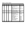


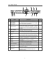

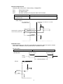
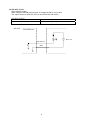
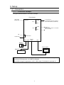


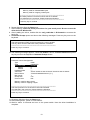


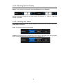

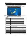

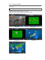
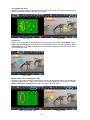

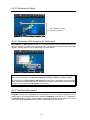

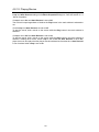
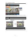

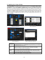
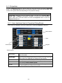


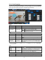
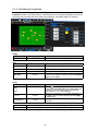

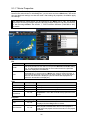

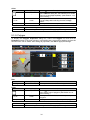
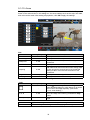
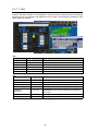

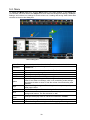

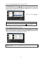
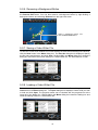
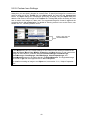

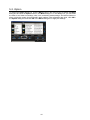
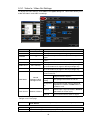
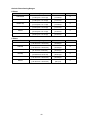
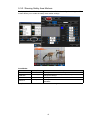
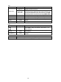

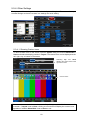


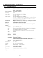
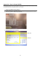
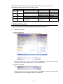
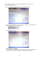

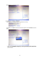
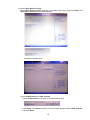
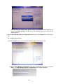


![MBP-100PD取扱説明書[PDF:1.1MB]](http://vs1.manualzilla.com/store/data/006610502_2-39f3623fc3ee971ebb71a027b67a85fa-150x150.png)

![FVW-500HS取扱説明書[0.0.1_SN0081:18.4MB] - for](http://vs1.manualzilla.com/store/data/006629131_2-3ac0081ae4846017a2adbc45c74d2ec4-150x150.png)

![VTW Software Operation manual[PDF:17.4MB] - FOR](http://vs1.manualzilla.com/store/data/005725901_1-df2c6d7f9199f46fcf33ffa12e63545b-150x150.png)