1
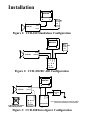
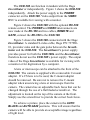
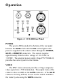
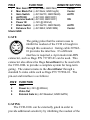
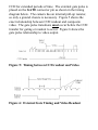
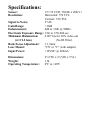
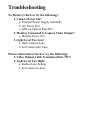
User’s Manual
DAGE-MTI
CCD-100
Camera System
Purchaser’s Record
Model Name: DAGE-MTI CCD-100
Serial Number:
Dealer’s Name:
Dealer’s Address:
Dealer’s Phone Number:
Date Purchased:
P.O. Number:
Introduction
The CCD-100 camera system is a fiscally
responsible approach to any imaging situation. The
camera automatically adjusts to any light situation to
provide clear, crisp images for even the most
demanding application. In those times when control is a
necessity, the camera's automatics can be switched off,
allowing control of those parameters that are important
to you. Camera adjustments can also be remote
controlled using the optional RC100 remote. (P/N
207672-01).
The CCD-100 uses the latest in circuitry and design
to provide images that will dazzle in even the toughest
light situations. The camera's automatic controls
provide exceptional performance from high light levels
to the dimmest environments. And if additional
sensitivity is needed, no problem. Just attach the CCD100 to the Dage InvestiGater and extend the camera's
exposure time to whatever is required. The combination
of the CCD-100 and InvestiGater allow a low cost
alternative to those expensive cameras and frame
grabbers that deliver only a fraction of the capability at
a great premium. And with our Dage-MTI series of
products, you won't be spending a lot of time setting up
your system. That leaves time for what you purchased
the camera for in the first place; to get the images
needed to perform your job.
DAGE-MTI offers our customers state-of-the-art video
technology… with an eye on your image.
Installation
MONITOR
WALL
MOUNT
ADAPTER
P/S
VIDEO
CCD100
POWER
Figure 1: CCD-100 Standalone Configuration
MONITOR
WALL
MOUNT
ADAPTER
P/S
GATE
POWER
GATE
VID OUT
REMOTE
REMOTE
CCD100
RC100
Figure 2: CCD-100/RC-100 Configuration
MONITOR
GATE
REMOTE
POWER
VID OUT
WALL
MOUNT
ADAPTER
CAMERA
TABLE TOP
SWITCHING
P/S
REMOTE
CCD100
P/S
WARNING:
DO NOT USE WALL MNT ADAPTER
WHEN USING INVESTIGATER.
RC100
INVESTIGATER
NOTE: INVESTIGATER POWER SWITCH CONTROLS CAMERA
POWER. RC100 POWER SWITCH IS NON-OPERABLE.
(OPTIONAL)
Figure 3: CCD-100/Investigater Configuration
The CCD-100 can function in tandem with the Dage
InvestiGater or independently. Figure 1 shows the CCD-100
independently. Attach the power supply to the POWER
connector on the CCD-100. Video output from the VIDEO
BNC is available for viewing with a monitor.
Figure 2 shows the CCD-100 with the optional RC-100
remote control. The POWER and VIDEO interconnects are
now made at the RC-100 and two cables, REMOTE and
GATE, connect the RC-100 to the CCD-100.
Figure 3 shows the CCD-100 connected with the Dage
InvestiGater. A standard S-video cable, Dage P/N 73798001, provides video and the gate pulse between the InvestIGater and the CCD-100. The InvestiGater’s power supply
provides power for both the CCD-100L and the InvestiGater,
therefore do not use the CCD-100’s power supply. The output
video of the Dage InvestiGater is available for viewing with
a monitor or for digitization by a computer.
A lens or microscope can be attached to the front of the
CCD-100. The camera is supplied with a removable C-mount
adapter. If a CS lens is to be used, the C-mount adapter
should be removed. Be sure not to remove the C-mount
adapter when unscrewing a lens or microscope from the
camera. The camera has an adjustable back focus that can be
changed through the use of a flat bladed screwdriver. The
adjustment is located on the top of the camera at the front.
Simply use the screwdriver to provide the correct back focus.
To achieve a picture, place the camera in the AUTO
BLACK and AUTO GAIN positions. This will ensure that the
camera will be able to provide an acceptable image regardless
of light level.
Operation
Figure 4: CCD-100 Rear Panel
POWER
The green LED located at the bottom of the rear panel
between the GAM switch and the POL switch lights when
power is supplied to the camera either through the POWER,
GATE, or REMOTE connectors. The camera requires
approximately 200mA with a voltage of +10.5VDC to
+18VDC. The external power supply, Dage P/N 738044-02,
provides the correct power to the camera.
VIDEO
The BNC video connector provides a 1Vp-p composite
video signal into a 75Ω termination. The output video of the
camera is also available at the GATE connector. If the GATE
connector is being utilized, be sure not the double terminate
the video by also using the VIDEO connector.
GAIN
The output level of the camera is determined by the
GAIN controls. The gain can be in one of three modes: MAN,
AUTO, or AUTO EE.
MAN GAIN
When the GAIN switch is in the MAN position, the
output level of the camera is determined by the rear
panel GAIN pot located above the GAIN switch. This pot
has a range of about 20db.
AUTO GAIN
The camera senses the output video level and adjusts
the gain to maintain a full level signal when the GAIN
switch is in the AUTO position. This position ensures
that the camera is providing a nominal output, but it is
not useful in applications where quantitative
measurements are needed. In those instances, the camera
should be in the MAN gain position.
AUTO EE
This gain position allows the camera to use the full
range of its automatics in the quest of providing a
standard output signal level. In addition to the use of the
automatic gain controls, the AUTO EE mode uses the
Electronic Exposure capabilities of the camera to
increase the dynamic range of the CCD. By shuttering
the CCD off for a portion of the video period, the camera
is capable of providing images under enormous light
differences. The camera can shutter down to 1/50,000
sec.
Note: When using the camera in the AUTO EE mode
under certain types of lighting such as fluorescent, the
camera's output signal may seem as though it is
changing in level. This is due to the cyclical nature of the
fluorescent light. While the human eye is not capable of
viewing the light difference cycle of fluorescent lighting,
the shuttered CCD is able to see it.
BLACK LEVEL
The black level determines the output level of the darkest
portions of the image. The BLK switch allows either a
manual or automatic mode to set the output video's blacks.
MANUAL
In the MAN black position, the video black level is
determined by the BLACK pot located above the BLACK
switch. This control allows the user to set the black level
to the desired position. Note that the detail below the
black set point will be lost, so the black level should be
set such that all of the useful information is visible.
AUTO
In the AUTO black position, the darkest portions of
the video signal are determined by the camera. This
position is useful in applications where the contrast level
of the incoming light is low and it is necessary for the
camera to expand that contrast. The camera will take the
darkest portion of the signal, which may not be close to
black in reality, and pull it down to black. This has the
effect of actually "stretching" the contrast of the signal.
Care should be taken to realize that the output signal may
not truly represent the input light level when the camera
is in this position.
ENHANCE
This pot determines the sharpness of the output picture.
To sharpen the picture, rotate the pot to the right. In low light
situations where the gain of the camera is high, it may be
better to not use as much enhancement since it also increases
the amount of noise in the output picture.
GAMMA
Gamma is a non-linear process added to the output video
to compensate for the characteristics of a monitor. When
GAMMA is ON, the blacks will tend to be stretched in
contrast, while the whites will be compressed. If the camera
is being used for measurement purposes, the GAMMA should
be in the OFF position.
POLARITY
In certain situations, it may be convenient to reverse the
output video image. When the POL switch is set to POS, the
output video is normal. In the NEG position, the video is
inverted, with blacks being white and whites being black.
REMOTE
This 8 pin connector allows the rear panel
functions to be remoted. Care should be
taken to insure the placement of the rear
panel controls to the REMOTE SET
positions as indicated in the table when
remoting the functions. The mating
connector to the REMOTE port is a male 8-pin mini-DIN
connector such as Dage P/N 738129-02.
PIN #
1
2
3
4
5
6
7
8
Shield
FUNCTION
REMOTE SET POS
Man Gain Pot (+5V=Max; GND=Min)
Man Black Pot (+5V=Dark; GND=Light)
Gain Switch
(+5V=AUTO; GND=MAN)
AUTO EE
(+5V=ON; GND=OFF)
Gamma Switch (+5V=ON; GND=OFF)
Power IN
(+12V @ 200mA)
Black Switch (+5V=AUTO; GND=MAN)
Enhance Pot (+5V=MAX; GND=MIN)
GND
Center
Center
AUTO
ON
AUTO
Center
GATE
The gating pulse that the camera uses to
inhibit the readout of the CCD is brought in
through this connector. Gating cable 20766301 provides the interface. If a different
interface is required, a 4-pin male mini-DIN
connector, such as Dage P/N 737129-01 can be used. This
connector also allows the Dage InvestiGater to be used with
the CCD-100L to provide a complete system for long-term
gating. The camera mates to the InvestiGater through a
standard S-video cable such as Dage P/N 737980-01. The
pin-out and interface is as follows:
PIN # FUNCTION
1
2
3
4
GND
Power In (+12V @ 200mA)
Video Out
External Gate In (+5V=Readout; GND=GATE)
GATING
The CCD-100L can be externally gated in order to
provide additional sensitivity by inhibiting the readout of the
CCD for extended periods of time. The external gate pulse is
placed on the GATE connector pin as shown in the timing
diagram below. The camera has an internal pull-up resistor,
so only a ground closure is necessary. Figure 5 shows the
exact relationship between CCD readout and composite
video. The gate pulse transitions must occur before the CCD
transfer for gating or readout to occur. Figure 6 shows the
gate pulse relationship to video output.
Figure 5: Timing between CCD readout and Video
Figure 6: External Gate Timing and Video Readout
Specifications:
Sensor:
Resolution:
1/3" IT CCD, 768(H) x 494(V)
Horizontal: 570 TVL
Vertical: 350 TVL
Signal to Noise:
57 db
Gain Range:
>18db
Enhancement:
0db to +8db @ 5MHz.
Electronic Exposure Range: 1/60 to 1/50,000 sec.
Minimum Illumination:
0.007 lux for 20% video out
(w/ f/1.2 lens)
(No IR Filter)
Back Focus Adjustment:
± 1.9mm
Lens Mount:
"CS" or "C" (with adapter)
Input Power:
+12VDC @ 200mA
Dimensions:
Weight:
Operating Temperature:
2¼"(W) x 2½"(H) x 5"(L)
1 lb.
0ºC to +40ºC
Troubleshooting
No Picture (Check or try the following):
1. Camera Power On?
a. External Power Supply Attached?
b. AC Power On?
c. LED on Camera Rear On?
2. Monitor Connected to Camera Video Output?
a. Monitor Power On?
3. Light Level Too Low?
a. Open Camera Lens.
b. Set Camera into Auto.
Picture Saturated: (Check or try the following):
1. Video Output Cable Terminated Into 75Ω?
2. Light Level Too High?
a. Reduce Lens Setting.
b. Set Camera in Auto.
Warranty
The DAGE-MTI CCD-100 is warranted to be free of
defects in material and workmanship in normal use for a
period of one year from the original date of purchase from
DAGE-MTI.
This warranty does not apply to units which have been
subject to abuse, neglect, accident, improper installation, or
on which the serial number has been removed or damaged.
Units that have been altered without the prior permission of
DAGE-MTI are not covered by this warranty.
This warranty does not apply to other equipment
furnished by DAGE-MTI, which is listed or otherwise
identified as manufactured by another and therefore shall be
covered by the other manufactures’ applicable warranty.
Limitations
1. This warranty is valid only if the malfunctioning unit is
returned to DAGE-MTI service depot. This warranty does
not cover on-location service. If warranty work is needed,
the following should be contacted:
DAGE-MTI, INC.
Customer Service
701 N. Roeske Ave.
Michigan City, IN 46360
(219) 872-5514
Fax: (219) 872-5559
[email protected]
2. This warranty does not cover:
a. Problems caused by or inflicted upon associated
equipment such as digitizing systems, video tape
recorders, cameras, microscopes, etc.
b. Damage caused by accident, misuse, improper power
source, fire, flood, lightning, other acts of God, war,
and repair or alteration by other than a DAGE-MTI
authorized service organization.
c. Labor or incurred charges required in removing or
installing the Product, down time, failure of the
Product to perform properly, and any consequential
damages.
d. Transit damage.
3. Unit must be properly packaged (in original packing, if
possible) when being returned under warranty.
DAGE-MTI Inc.
701 N. Roeske Ave.
Michigan City, IN 46360
(219) 872-5514
Fax: (219) 872-5559
E-mail: [email protected]
http://www.dagemti.com
970291-01
8/13/02