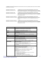
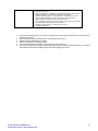
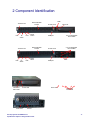
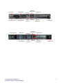
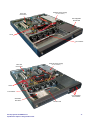
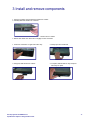
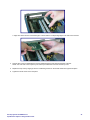
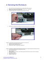
1
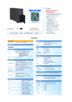
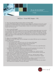
User Manual, 1U NEBS Servers OSS-MB-1U-SYS OSS-MB-1U-SYS-5D Table of Contents 1 Overview 1.a Introduction.................................................................................................................................... 3 1.b Description .................................................................................................................................... 4 1.c Unpacking instructions................................................................................................................... 5 2 Component Identification 2.a Front panel .................................................................................................................................... 6 2.b LED panel identification ................................................................................................................. 6 2.c Rear panel ..................................................................................................................................... 6 2.d Internal .......................................................................................................................................... 8 3 Install and Remove Components 3.a Removing and replacing hot swappable drive unit ........................................................................ 9 3.b Removing top panel....................................................................................................................... 10 3.c Installing the solid state hard drive ................................................................................................ 10 3.d Removing memory ........................................................................................................................ 11 3.e Installing memory .......................................................................................................................... 11 3.f Installing host card ......................................................................................................................... 11 4 Servicing the Enclosure 4.a Removing the power supply .......................................................................................................... 13 4.b Installing the power supply ............................................................................................................ 13 4.c Cleaning the air filter ...................................................................................................................... 13 4.d Installing rack slides ...................................................................................................................... 14 One Stop Systems 1U NEBS Servers Specifications subject to change without notice -2- 1 Overview 1.a Introduction The information contained in this manual may be subject to technical alteration as a result of constant upgrading by One Stop Systems products. The attached documentation does not entail any guarantee on the part of One Stop Systems with respect to technical processes described in the manual or any product characteristics set out in the manual. One Stop Systems does not accept any liability for any printing errors or other inaccuracies in the manual unless it can be proven that One Stop Systems is aware of such errors or inaccuracies or that One Stop Systems is unaware of these as a result of gross negligence and One Stop Systems has failed to eliminate these errors or inaccuracies for this reason. One Stop Systems expressly informs the user that this manual only contains a general description of technical processes and instructions, which may not be applicable in every individual case. In cases of doubt, please contact One Stop Systems. Note on the Guarantee: Due to their limited service life, parts which by their nature are subject to a particularly high degree of wear (wearing parts) are excluded from the guarantee beyond that provided by law. This applies, for example, to batteries. Exemption from the Guarantee Obligation: One Stop Systems shall be exempted from its guarantee obligations if the user fails to observe the safety instructions. One Stop Systems can only guarantee the safety, reliability and performance of the device if all of the safety instructions are observed. Exclusion of Accident Liability Obligation: One Stop Systems shall be exempted from the statutory accident liability obligation if the user fails to observe the safety instructions. Liability Limitation: In the event of damage to the device caused by failure to observe the safety regulations, One Stop Systems shall not be required to honor the guarantee even during the guarantee period and shall be exempted from the statutory accident liability obligation. Safety Instructions Please read this section carefully and observe the instructions for your own safety and correct use of the device. Observe the warnings and instructions on the device and in the manual. One Stop Systems products leave the factory in a perfectly safe condition. In order to maintain this condition and ensure safe operation, the user must observe the instructions and warnings contained in this manual. The device must be used in accordance with the instructions for use. The equipment must be installed in accordance with the National Standards and/or Electrical Codes of the country in question. The electrical installations in the room must correspond to the requirements of the respective regulations. Take care that there are no cables, particularly mains cables, in areas where persons can trip over them. Use only the cable supplied by One Stop Systems. Do not set up the device where it is exposed to direct sunlight, in the proximity of heat sources or in a damp location. Make sure the device has adequate ventilation. Only devices and components may be connected to the interfaces of the system, which fulfill the requirements of a SELV circuit (Safety extra Low Voltage) in accordance with EN60950. It must be assumed that safe operation is no longer possible: o If the device has visible damage. o If the device no longer functions. In these cases the device must be shut down and secured against unintentional operation. If extensions are made to the device the legal stipulations and the device specifications must be observed. Assembly, extensions, new settings, alterations or repairs may be carried out only as authorized by One Stop Systems. Adjustment, maintenance or repair on the open device may be carried out only as authorized by One Stop Systems. Only original accessories approved by One Stop Systems may be used. The inside of the enclosure is considered a “Service Access Area.” Warning! Hazardous voltages exist. One Stop Systems 1U NEBS Servers Specifications subject to change without notice -3- 1.b Description ® 1U NEBS server with Intel 5520 Series Server Board with two Intel Xeon (Nehalem) 5500 series processors available with either AC or DC inputs. OSS-MB-1U-SYS-5520-2.0-AC OSS-MB-1U-SYS-5520-2.53-AC Eight versions available: 1U NEBS server with Intel Server Board S5520UR with dual Intel Xeon (Nehalem) 5500 series processors, 550W AC power supply, one 2.5” internal fixed hard drive mounting plus one 3.5” hot swappable SATA/SAS drive shuttle OSS-MB-1U-SYS-5520-2.0-DC OSS-MB-1U-SYS-5520-2.53-DC 1U NEBS server with Intel Server Board S5520UR with dual Intel Xeon (Nehalem) 5500 series processors, 550W DC power supply with dual -48VDC inputs, one 2.5” internal fixed hard drive mounting plus one 3.5” hot swappable SATA/SAS drive shuttle OSS-MB-1U-SYS-5520-2.0-5HD-AC OSS-MB-1U-SYS-5520-2.53-5HD-AC 1U NEBS server with Intel Server Board S5520UR with dual Intel Xeon (Nehalem) 5500 series processors, 550W AC power supply, one 2.5” internal fixed hard drive mounting plus four 2.5” hot swappable SATA/SAS drive shuttles OSS-MB-1U-SYS-5520-2.0-5HD-AC OSS-MB-1U-SYS-5520-2.53-5HD-AC 1U NEBS server with Intel Server Board S5520UR with dual Intel Xeon (Nehalem) 5500 series processors, 550W DC power supply with dual -48VDC inputs, one 2.5” internal fixed hard drive mounting plus four 2.5” hot swappable SATA/SAS drive shuttles 1U NEBS Server Specifications Dimensions Cooling Air filter Storage Weight MTBF Chassis Power Integrated Intel® Server Board S5520UR Integrated On-Board Dimensions: 17”W x 1.75” H x 21”D Two configurations with front-to-rear air flow: Six 23CFM fans, two power supply fans, and two CPU blowers OR Six 15CFM fans, two power supply fans, and two CPU blowers Removeable air filter bracket with thumb screws Air Filter: One 30 ppi (pores per inch) air filter, open cell, polyfoam, UL 900 rating Two configurations: One 3½” SATA/SAS hard drive shuttle OR Four 2½" SATA/SAS hard drive shuttles and one 2½" fixed drive mounting 22 lbs. 100,000 hours USB connector on front panel Rack ears and rack slides are included 550W AC or DC power supply AC version: Single input on rear panel -48VDC version: Dual inputs on rear panel Outputs: +5 @ 30A, +12V @ 11A, -12 @ 1A, +3.3V @ 22A, -5V @ 1A Dual Intel® Xeon 5500 series processors (Nehalem) with either 2.0Ghz, 4Gb cache OR 2.53Ghz, 8Gb cache PCI Express expansion slots: One PCIe 2.0 x16 (via riser) Memory: up to 96GB in 12 DDR3 DIMM Sockets Storage: 6 SATA ports (3Gbps) via ICH10R with Intel® Embedded Server RAID Technology Intel® RAID support: Integrated SATA RAID levels 0/1/10 Temperature Range: 0° to 50°C (32° to 122°F) Relative Humidity: 10 to 90% non-condensing Shock: 30g acceleration peak (11ms pulse) Vibration: 5-17 Hz 0.5” double amplitude; displacement; 7-2000Hz, 1.5g acceleration Damp Heat (Humidity), DIN EN 60068-2-30, Method Db Variant 2 Random Vibration, HVO103en dated 2007-12, Class B Sine Vibration Frequency range: 5 HZ to 55 Hz Excursion: 0.15 mm, constant amplitude, (corresp. to 1.8 g at 55 Hz) Frequency range: 55 Hz to 150 Hz Acceleration: 0.5 g, constant Test speed: approx. 1 octave per minute, logarithmic Stress duration: 12 minutes on each of three perpendicular axes One Stop Systems 1U NEBS Servers Specifications subject to change without notice -4- Agency Meets or exceeds the following requirements: Certified, FCC Class A Safety UL/CSA-60950-1, EN60950-1, IEC60950-1, CB Scheme with all country deviations, IEC825-1, 2, CFR21 part 1040, CNS1436, GB4943 RFI/EMC EN55022 Class A, 47 CFR 15B Class A, ICES-003 Class A, VCCI Class A, AS/NZ 3548 Class A, CNS 13438 Class A, KSC 5858 Class A, GB9254 Class A, EN61000-4-6, GB17625.1, EN6100-3-3 Immunity EN55024, IEC 61000-4-2, IEC 61000-4-3, IEC 61000-4-4, IEC 61000 4-5, IEC 61000-4-6, IEC-61000-4-8, IEC 61000-4-11 Regulatory markings CE, FCC, ICES-003, VCCI, UL/cUL Certified to NEBS level 3 1.c Unpacking Instructions 1. 2. 3. 4. 5. 6. If the carton is damaged when you receive it, request that the carrier's agent be present when you unpack and inspect the equipment. After unpacking, verify that all items listed in the packing list are present. Observe all proper ESD safety procedures. Inspect the equipment for shipping damage. Save all packing material for storage or return shipment of the equipment. For repairs or replacement of equipment damaged during shipment, contact One Stop Systems, Inc. to obtain a Return Materials Authorization (RMA) number and further shipping instructions. One Stop Systems 1U NEBS Servers Specifications subject to change without notice -5- 2 Component Identification 2.a Front panel components OSS-MB-1U-SYS Removable filter bracket Thumb screw LED LED ID switch Reset button LEDs Thumb screw USB port Drive lock 3.5” hot swappable drive shuttle OSS-MB-1U-SYS-5D Removable filter bracket Thumb screw LED ID switch LED Reset button Thumb screw USB port 2.5” hot swappable drive shuttles LEDs 2.b LED panel components OSS-MB-1U-SYS Hard drive status LED Power LED Power LED OSS-MB-1U-SYS-5520-5HD Power LED Hard drive status LED ID LED One Stop Systems 1U NEBS Servers Specifications subject to change without notice -6- 2.c Rear panel components OSS-MB-1U-SYS-DC Grounding DC power supply Mouse port Keyboard port External Ethernet ports Serial port USB ports Video connector Thumb screw Ground banana jack Cable holder OSS-MB-1U-SYS-5D-AC AC power supply Mouse port Keyboard port One Stop Systems 1U NEBS Servers Specifications subject to change without notice External Ethernet ports Serial port USB ports Video connector Thumb screw Ground banana jack Cable holder -7- 2.d Internal components OSS-MB-1U-SYS-DC Host card riser board 550W DC power supply (AC also available) Hot swappable drive shuttle CPUs Fan modules OSS-MB-1U-SYS-5D-AC Host card riser board 550W AC power supply (DC also available) CPUs Fan modules Hot swappable drive shuttles Solid state hard drive Thumb screw One Stop Systems 1U NEBS Servers Specifications subject to change without notice -8- 3 Install and remove components 3.a Remove and replace hot swappable drive unit OSS-MB-1U-SYS 1. Using key provided, unlock hard drive shuttle from chassis. 2. Carefully slide drive shuttle out of chassis. 3. Return drive to chassis. 4. Relock drive shuttle lock. Drive will not engage if unit is not locked. OSS-MB-1U-SYS-5D 1. Press lock mechanism on right side of drive bay. 2. Gently open drive shuttle tab. 3. Using tab, slide shuttle from chassis. One Stop Systems 1U NEBS Servers Specifications subject to change without notice 4. To replace, slide shuttle into bay and press lock firmly into place. -9- 3.b Removing top panel 1. 2. 3. If unit is operational, power down and unplug unit. Remove unit from rack. Remove top panel by unscrewing thumb screw on rear of unit, screwdriver may be used if too tight. Slide top panel toward back and gently lift from chassis. 1. 2. Remove the empty solid state hard drive chassis from the unit. Install hard drive into the chassis using the four screws provided with the chassis. 3.c Installing the solid state hard drive Chassis screws Chassis screws 3. Insert data and power cables into the hard drive. One Stop Systems 1U NEBS Servers Specifications subject to change without notice - 10 - 4. 5. Reinsert the hard drive chassis into the unit lining up the tabs on the bottom of the chassis to the corresponding lances on the unit ensuring all cables are out of the way. Tighten the thumbscrew. 3.d Removing memory 1. Release memory by depressing the two thumb levers simultaneously. 2. Gently pull the memory straight up and out of the connector. 3.e Installing memory 1. Open the thumb levers at each edge of the selected memory connector. 2. Align the memory matching the notches with the corresponding ridges in the connector. 3. Gently press down on the memory until it is seated in the connector. The thumb levers should pop into position. 3.f Installing the host card 1. Remove the back filler panel by lifting up and then to the left. 2. Gently pull the host adapter riser card straight up and out of the connector. One Stop Systems 1U NEBS Servers Specifications subject to change without notice - 11 - 3. Align host card to the riser card matching the notches with the corresponding ridges in the riser card connector. 4. Seat the riser card to its motherboard connector while aligning the host card with the back of the unit. NOTE: The host card is held in place by the metal clips on the back of the unit and the top cover. 5. Replace the top cover by aligning it with the coordinating notches on the chassis. Slide the top panel into place. 6. Tighten the thumb screw on the rear panel. One Stop Systems 1U NEBS Servers Specifications subject to change without notice - 12 - 4 Servicing the Enclosure 4.a Removing the power supply 1. 2. 3. Power down the unit and unplug the power connector from the rear of the unit. NOTE: You may perform this operation with the chassis lid on or off the unit. Straighten the power supply removal handle. Loosen the thumb screw. A screwdriver may be used if it is too tight. 4. Using the power supply removal handle, gently pull the power supply out of the chassis. 4.b Installing the power supply NOTE: You may perform this operation with the chassis lid on or off the unit. 1. Insert the new power supply into the opening. 2. Tighten the power supply thumb screw. 3. Fold the power supply removal handle in toward unit. 4.c Cleaning the air filter NOTE: It is necessary to clean the air filter frequently to ensure proper cooling and optimum system performance. 1. Loosen the two thumb screws on front panel of the unit. 2. Remove the filter bracket. 3. Remove the filter. NOTE: Replace with new filter or clean filter thoroughly with clear water and allow it to dry completely. 4. Fit the filter to the unit. 5. Replace the filter bracket. 6. Tighten the thumb screw. One Stop Systems 1U NEBS Servers Specifications subject to change without notice - 13 - 4.d Installing rack slides 7. 8. Slide unit into rack. Extender Install the slides into the rack using an extender if necessary. Attach the slides to unit with five screws on each side.