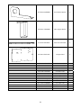
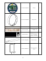
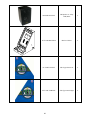
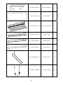
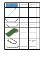
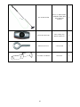
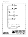
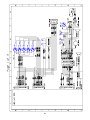
1
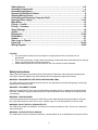
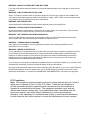
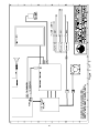
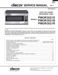
Service Manual
Rev 1.0
For Parts or Service contact
Betson Enterprises at 1(800) 828-2048
© Chicago Gaming Company 2009 All Rights Reserved
Safety Notices……………………………………………………………………….….……2-3
Assembly Components………………………………………………………………………4
Assembly Instructions……………………………………………………………………..5-7
Removal of Ball Mech Cabinet………………………………………………………………8
Aligning Motion Sensor……………………………………..………………………………..9
Accessing and Removing Computer Shelf……………………………………………...10
Servicing Floor Lamps……………………………………………………………….….11-12
Main Menu……………………………………………………………………………………..13
Pricing – Credits……………………………………………………………………………...13
Pricing – Currency…………………………………………………………………………...14
Game Settings………………………………………………………………………………...14
Audits..……………………………….…………………………………………………….…..15
Diagnostics………….………………………………………………………..…….……..16-20
Reset Menu……………………………………………………………………………………20
Update……………….…………………………………………………………………………21
Save Logs to Thumb………………..……..……………….………………………….….…21
Parts List……………….……………….……………………..……….…….…….……...22-42
Wiring Diagram……………………………………………………………………………43-45
CAUTION:
• The specifications of this product are subject to change without notice for reasons such as
performance.
• The content of this game, its main devices and design are protected under each federal law concerning
patent, copyright and other intellectual properties.
• Unauthorized reproduction of this document or any of its contents is strictly forbidden.
Safety Instructions
Safety instructions apply to operators and service personnel. Read these instructions before preparing the
video game machine (VGM) for play. Other safety instructions appear throughout this manual.
WARNING: TRANSPORTING THE VIDEO GAME MACHINE (VGM).
The VGM contains glass and fragile electronic devices. Use appropriate care when transporting. Avoid rough
handling when moving the VGM.
WARNING: DISCONNECT POWER.
Always turn the power OFF and unplug the VGM before attempting service or adjustments unless otherwise
instructed. Installing or repairing components with the power switched ON can damage the components and
void warranty.
WARNING: GROUND GAMES.
Avoid electrical shock! Do not plug in the VGM until you have inspected and properly grounded it. Only plug
into a grounded, three-wire outlet. Do not use a “cheater” plug, or cut off the ground pin on the line cord.
WARNING: DO NOT INSTALL NEAR WATER JET
This VGM is not suitable for installation in an area where a water jet would be used. Do not use a water jet to
clean the machine.
WARNING: AVOID ELECTRICAL SHOCKS.
This VGM does not utilize an isolation transformer. Internal cabinet AC is not isolated from the external AC line.
2
WARNING: HANDLE FLOURESCENT TUBE WITH CARE.
If you drop a fluorescent tube and it breaks, it will implode! Shattered glass can fly eight feet or more from the
implosion.
WARNING: CHECK POWER SELECTOR, LAMP.
Set the 115/230 VAC selector switch on the power supply for the correct line voltage on the installation site.
Verify that the fluorescent lamps are rated for the proper line voltage. NOTE: There are two fluorescent lamps
in the marquee and one fluorescent lamp in the main cabinet.
WARNING: USE PROPER FUSE.
Avoid electrical shock! Replacement fuses must be identically rated to the original fuse!
WARNING: ATTACH CONNECTORS PROPERLY.
Be sure all connectors mate properly. If connectors do not slip in easily, do not force them. Connectors are
often keyed and only connect one way. Check for correct orientation.
WARNING: USE EXTREME CARE WHEN HANDLING PC.
The PC contains sensitive components. Do not handle roughly. Call your distributor before servicing PC
internal components. Ask about warranty information as it relates to the PC.
WARNING: IF POWER CORD IS DAMAGED
If the supply cord is damaged it must be replaced by a special cord or assembly available from the
manufacturer or service agent.
WARNING: HAZARD TO EPILEPTICS.
A very small portion of the population has a condition that may cause them to experience epileptic seizures or
have momentary loss of consciousness when viewing certain kinds of flashing lights or patterns that are
present in our daily environment. These persons may experience seizures while watching some kinds of
television pictures or playing certain video games. People who have not had any previous seizures may
nonetheless have an undetected epileptic condition.
If you or anyone in your family has experienced symptoms linked to an epileptic condition (e.g., seizures or loss
of awareness), immediately consult your physician before using any video games.
We recommend that parents observe their children while they play video games. If you or your child experience
the following symptoms: dizziness, altered vision, eye or muscle twitching, involuntary movements, loss of
awareness, disorientation, or convulsions, DISCONTINUE USE IMMEDIATELY and consult your physician.
FCC Compliance
Note: This equipment has been tested and found to comply with the limits for a Class A
digital device, pursuant to Part 15 of the FCC Rules. These limits are designed to
provide reasonable protection against harmful interference when the equipment is
operated in a commercial environment. This equipment generates, uses, and can
radiate radio frequency energy and, if not installed and used in accordance with the
instructions manual, may cause harmful interference to radio communications.
Operation of this equipment in a residential area is likely to cause harmful interference,
in which case the user will be required to correct the interference at his own expense.
3
Assembly Components
Ball Mech
Cabinet
Monitor Cabinet
with Marquee
Putt Floor
Green
Handrail
Ball Chute
Monitor
Guard Bar
Hardware
(10) ¼-20 x 1-1/2” Hex Head Bolts
(4) ¼-20 x 2-1/4” Hex Head Bolts
(12) ¼” x 5/8” OD Flat Washers
(4) #8 x ½” Black Phillips Pan Head
(4) ¾” Black Mounting Dome Plug
4
Assembly Instructions
WARNING!
CABINET MUST BE
LEVEL FOR GAME TO
FUNCTION
1
Level the Monitor Cabinet.
2
Put the Green in position on the
Monitor Cabinet.
3
Using (4) of the ¼-20 x 1-1/2”
bolts and ¼” washers
provided, secure the Green to
the Monitor Cabinet. Use
black hole plugs to cover holes
after bolts have been installed.
5
Place the Handrail in the
mounting holes on the Floor.
4
5
Place something (cardboard,
cloth, etc.) on the ground to
protect the artwork. Lift the
Floor up and secure Handrail
from bottom with (4) ¼-20 x 21/4”bolts and ¼” washers.
6
With the leg levelers on the
Floor in the lowest position,
move the Floor into place.
Connect the 12V DC Lamp
Cable (which extends from the
Floor) to the corresponding
harness, which extends from
the Monitor Cabinet. Make
sure the cable does not get
pinched when pushing the
cabinets together
Using the leg levelers, adjust
the Floor until it is the same
height as the Monitor Cabinet
and Green.
7
6
Lift the carpet on the Green at
the white tabs. Bolt the Green
to the Floor using (4) ¼-20 x
1-1/2” bolts and ¼” washers.
8
FLOOR AND GREEN ARE STILL ATTACHED AT
THIS STEP
9
Putting
Floor
Ball Mech
Cabinet
Once in position, bolt the Floor
to the Monitor Cabinet on
BOTH SIDES below the
speakers from inside the Ball
Mech Cabinet and Coin Door
Cabinet using 2 ¼-20 x 1-1/2”
bolts and ¼” washers.
After everything is assembled
and bolted together, attach the
Ball Chute. Slide one foot of
the Ball Chute under the Ball
Chute Foot below the ball exit.
Make sure the Ball Chute is
aligned with the pilot holes and
secure it with the (2) #8 x ½”
Black Screws.
10
7
Removal of Ball Mech Cabinet
If the cabinet is too wide to fit through a doorway with the Ball Mechanism Cabinet attached, it can be
easily removed and reattached.
1
Open the top door and side
door on the Ball Mech
Cabinet.
2
Remove the 2 bolts
connecting the cabinets, the
2 nuts connected to the
Monitor Guard Bar and the
plate where you removed the
nuts.
Remove the Back Door and
disconnect the AC Wire
Harness and Ball Mech
Harness that run between
the Monitor Cabinet and
Ball Mech Cabinet.
3
Pull the disconnected
harnesses back into the Ball
Mech Cabinet and close the
doors. Lift the Ball Mech
Cabinet straight up 1 inch to
free it from the Ball Mount
Brackets, and then pull it
away from the Monitor
Cabinet. The Monitor
Guard Bar should still be
connected to the Control
Panel Cabinet
4
To reattach the Ball Mech Cabinet,
just follow the previous steps in reverse order.
8
Aligning Motion Sensor
The motion sensor is aligned before you receive it, but it is possible
that some movement has occurred during shipment.
REMOVE BACK DOOR TO
ACCESS MOTION SENSOR
NOTE: For better visibility, use the removed back door to shield
light from the cabinet. When the back door is open, light
reflecting off the motion sensor guard tends to wash out the
image, making it more difficult to see.
Open the coin door and press the Menu button on the Service Panel.
Using the Up and Down buttons on the Control Panel, move to
Diagnostics and press Start. From this menu, select Motion Sensor.
Look at the box labeled “Live Feed.” This shows you what the motion
sensor is currently seeing.
If the motion sensor is correctly aligned, you should see equal black
triangles on both sides of the image and a thin silver line, which is the top of the Ball Gate, at the bottom
of the screen. THIS LINE MUST BE HORIZONTAL FOR THE MOTION SENSOR TO TRACK
ACCURATELY. If the image DOES NOT appear as described, use the guide below to determine
how you must adjust the motion sensor.
See Motion Sensor Test on page 19 for information on adjusting the ball speed.
PERFECT
SENSOR TOO LOW
BEND SENSOR
BRACKET UP
Live Feed
Live Feed
MUST BE PERFECTLY HORIZONTAL
SENSOR TOO HIGH
BEND SENSOR
BRACKET DOWN
Live Feed
SENSOR NOT CENTERED IMAGE NOT HORIZONTAL
LOOSEN THE TWO
SCREWS SHOWN
BELOW, SWIVEL THE
SENSOR LEFT OR
RIGHT, THEN TIGHTEN
THE SCREWS
LOOSEN THE TWO
SCREWS SHOWN BELOW
AND TWIST THE SENSOR
SO THE WHITE LINE AT
THE BOTTOM IS
PERFECTLY HORIZONTAL.
WHEN IN PLACE, TIGHTEN
THE SCREWS
Live Feed
Live Feed
9
Accessing and Removing Computer Shelf
The computer shelf is located at the rear of the Coin Door Cabinet. The computer shelf can be accessed
by removing the door on the back of the Coin Door Cabinet. Remove the thumbscrew and slide the
computer shelf back.
There are nine cables that need to be disconnected from the Computer Shelf to completely remove it
from the cabinet. These are the Fan Power Harness, Power Cable to the Power Supply, Coin Door
Harness, Control Panel Harness, Ball Mech Harness, Speaker Harness, DVI Cable, USB Extension
Cable and the Motion Sensor’s USB Cable
1. TURN POWER OFF AND UNPLUG FROM WALL!
2. Remove the back door of the Coin Door Cabinet.
3. Disconnect the Fan Power Harness from the ATX Power Supply.
4. Remove the thumbscrew that holds the Computer Shelf in place.
5. Pull the computer shelf out just enough so that you can see all of the I/O Board and Power
Supply.
6. Disconnect the A/C Power Cable from the Power Supply.
7. Disconnect the 4 cable connectors that are attached to the face of the I/O Board. These are the
Coin Door Harness, Control Panel Harness, Ball Mech Harness and the Speaker Harness.
8. You can leave the 4-pin power connecter attached to the top of the board, as well as the USB
cable and Audio Cable.
9. Continue pulling the shelf out of the cabinet.
10. Disconnect the monitor’s DVI Cable from the Video Card that is connected to the motherboard.
11. Disconnect the Motion Sensor USB Cable and USB Extension Cable from Motherboard.
10
Servicing Floor Lamps
The lamps in the floor are wired in sets of 2. Each set consists of 1 inverter and 2
lamps. There is a single cable that runs from the Monitor Cabinet to each inverter, as
shown below. Each lamp has its own cable, which connects to the other side of the
inverter.
Because both lamps are plugged into the same inverter, you must remove both
blocks in a set when servicing a lamp.
The Floor Light Cable
connects to each inverter
The Floor Lamps are
wired in sets of 2
In a set, one block has an
inverter and the other doesn’t
See the next page for detailed instructions
11
1. Remove the bolts that hold the Floor to the Monitor Cabinet and remove the 4 bolts that mount the
Green to the Floor. You can leave the Green connected to the Monitor Cabinet.
2. Pull the Floor away from the Monitor Cabinet and disconnect the Floor Power Cable, which runs
between the two cabinets.
3. Pull the handrail down to the ground so that the Floor is vertical. Put something on the ground to
protect the art and Handrail from being scratched.
4. Remove the 4 screws for the pair of lamps that you have to remove. Slightly lift each block so you can
see which one has the inverter. Unplug both sets of white cables that are plugged into the inverter.
5. You can now remove and service the lamp or inverter.
6. When reinstalling the lamps, you must first install the lamp WITHOUT the inverter and run that lamp’s
cable to the other lamp’s mounting hole, as shown below. Now put the block with the inverter in position
and connect both of the lamps cables to the inverter
12
Main Menu
PUTT
CHICAGO GAMING
V 1.0.0
JUNE 30, 2009
The Service Panel is located behind the coin door
Main Menu
0000001
Menu
VOLUME 50
USE REAL CURRENCY
OFF
PRICING – CREDITS
PRICING – CURRENCY
GAME SETTINGS
AUDITS
DIAGNOSTICS
RESET MENU
UPDATE
SAVE LOGS TO THUMB
EXIT WITHOUT SAVING
EXIT AND SAVE
Service
Use the arrow buttons to navigate the menu
Volume – Set Volume from 0-100
Use Real Currency
– ON / OFF
PRESS UP AND DOWN TO ADVANCE ENTER TO SELECT
CREDITS: 0
Pricing – Credits
PUTT
CHICAGO GAMING
V 1.0.0
JUNE 30, 2009
Pricing Menu
FREE PLAY
OFF
COIN 1 (DBA) CREDITS
1
COIN 2Free
CREDITS
Play – ON / OFF 1
MAXIMUM CREDITS
99
9 HOLE GAME CREDITS
2
3 HOLE GAME CREDITS
1
3 HOLE CONTINUE CREDITS 1
INSERT COIN PROMPT INSERT COIN
RETURN TO MAIN MENU
Coin 1 (DBA) Credits – OFF / 1-10
Coin 2 Credits – OFFF / 1-10
Maximum Credits – 1-99
9 Hole Game Credits – 1-10
3 Hole Game Credits – 1-10
3 Hole Continue Credits – 1-10
Insert Coin Prompt – Insert Coin / Insert Key / Swipe Card
PRESS UP AND DOWN TO ADVANCE ENTER TO SELECT
Credits: 0
13
Pricing – Currency
PUTT
CHICAGO GAMING
V 1.0.0
JUNE 30, 2009
Pricing Menu
FREE PLAY
OFF
LOCALE
USA DOLLAR
COIN 1 (DBA) PER PULSE $0.25
COIN 2 PER PULSE
$0.25
9 HOLE GAME COST
$2.50
3 HOLE GAME COST
$1.00
3 HOLE CONTINUE COST $1.00
INSERT COIN PROMPT INSERT COIN
RETURN TO MAIN MENU
Free Play – ON / OFF
Locale – USA Dollar / England Pound
Coin 1 (DBA) Per Pulse – $0.00-$5.00
Coin 2 Per Pulse – $0.00-$5.00
9 Hole Game Cost – $0.25-$10.00
3 Hole Game Cost – $0.25-$10.00
3 Hole Continue Cost – $0.25-$10.00
Insert Coin Prompt – Insert Coin / Insert Key / Swipe Card
PRESS UP AND DOWN TO ADVANCE ENTER TO SELECT
Credits: 0
Game Settings
PUTT
CHICAGO GAMING
V 1.0.0
JUNE 30, 2009
GAME SETTINGS
DIFFICULTY
MEDIUM
ATTRACT SOUND
ON
ALLOW CONTINUES
ON
CONTINUE TIMER
30
METERS / YARDS
FEET
MAX STROKES OVER PAR
4
MINUTES TO TIMEOUT IDLE GAME 5
RETURN TO MAIN MENU
Difficulty – Easy / Medium Easy / Medium / Medium Hard / Hard
The difficulty level determines how much the
computer assists the player during putting. If a
player, aiming at the hole, hits the ball too far to the right,
the computer will partially correct the putt, moving the
ball closer to the hole. Easier difficulties correct more,
while harder difficulties correct less.
Attract Sound – ON / OFF / Low Volume
Allow Continues – ON / OFF / 1 / 2 / 3
Continue Timer – 15-45
Meters/Yards – Meters / Yards / Feet
Max Strokes Over Par – OFF / 1-10
Minutes to Timeout Idle Game – OFF / 1-15
PRESS UP AND DOWN TO ADVANCE ENTER TO SELECT
Credits: 0
14
Audits
Base Audits
PUTT
CHICAGO GAMING
V 1.0.0
JUNE 30, 2009
PUTT
CHICAGO GAMING
V 1.0.0
JUNE 30, 2009
AUDITS MENU
BASE AUDITS
GAME AUDITS
VEGAS AUDITS
HAWAII AUDITS
RETURN TO MAIN MENU
Game Audits
AUDITS
CURRENT
$0.00
LIFETIME
$0.00
COIN CHUTE 1
COIN CHUTE 2 (DBV)
TOTAL COINS
0
0
0
0
0
0
FREE PLAY STARTS
GAMES PLAYED
0
0
0
0
0
$0.00
0
$0.00
0Y 0D 00:00:00
0Y 0D 00:00:00
0Y 0D 00:00:00
0Y 0D 00:00:00
MONEY IN
SERVICE CREDITS
SERVICE CREDIT CURRENCY
TIME ON
PLAY TIME
PUTT
CHICAGO GAMING
V 1.0.0
JUNE 30, 2009
AUDITS
CURRENT
$0.00
LIFETIME
$0.00
50
52
0:00
34
1
0
0
50
52
0:00
34
1
0
0
9 HOLE GAMES
3 HOLE GAMES
3 HOLE CONTINUES
23
12
15
23
12
15
1 PLAYER CONTINUES
2 PLAYER CONTINUES
3PLAYER CONTINUES
4PLAYER CONTINUES
14
1
0
0
14
1
0
0
VEGAS GAMES
HAWAII GAMES
5
30
5
30
MONEY IN
GAMES PLAYED
GAMES X PLAYED
AVERAGE GAMETIME
1 PLAYER GAMES
2 PLAYER GAMES
3 PLAYER GAMES
4 PLAYER GAMES
30
PRESS UP AND DOWN TO ADVANCE ENTER TO SELECT
Credits: 0
PRESS SERVICE TO CLEAR CURRENT AUDITS
PRESS ENTER TO EXIT
Credits: 0
PRESS SERVICE TO CLEAR CURRENT AUDITS
PRESS ENTER TO EXIT
Credits: 0
Vegas Audits
PUTT
CHICAGO GAMING
V 1.0.0
JUNE 30, 2009
Hawaii Audits
AUDITS
CURRENT
LIFETIME
HOLE 1 PLAYS
HOLE 1 AVG SCORE
HOLE 1 AVG TIME
0
0
0
0
0
0
HOLE 2 PLAYS
HOLE 2 AVG SCORE
HOLE 2 AVG TIME
0
0
0
0
0
0
HOLE 3 PLAYS
HOLE 3 AVG SCORE
HOLE 3 AVG TIME
0
0
0
0
0
0
HOLE 4 PLAYS
HOLE 4 AVG SCORE
HOLE 4 AVG TIME
0
0
0
0
0
0
HOLE 5 PLAYS
HOLE 5 AVG SCORE
HOLE 5 AVG TIME
0
0
0
0
0
0
HOLE 6 PLAYS
HOLE 6 AVG SCORE
HOLE 6 AVG TIME
0
0
0
0
0
0
HOLE 7 PLAYS
HOLE 7 AVG SCORE
HOLE 7 AVG TIME
0
0
0
0
0
0
HOLE 8 PLAYS
HOLE 8 AVG SCORE
HOLE 8 AVG TIME
0
0
0
0
0
0
HOLE 9 PLAYS
HOLE 9 AVG SCORE
HOLE 9 AVG TIME
0
0
0
0
0
0
PUTT
CHICAGO GAMING
V 1.0.0
JUNE 30, 2009
AUDITS
CURRENT
LIFETIME
HOLE 1 PLAYS
HOLE 1 AVG SCORE
HOLE 1 AVG TIME
0
0
0
0
0
0
HOLE 2 PLAYS
HOLE 2 AVG SCORE
HOLE 2 AVG TIME
0
0
0
0
0
0
HOLE 3 PLAYS
HOLE 3 AVG SCORE
HOLE 3 AVG TIME
0
0
0
0
0
0
HOLE 4 PLAYS
HOLE 4 AVG SCORE
HOLE 4 AVG TIME
0
0
0
0
0
0
HOLE 5 PLAYS
HOLE 5 AVG SCORE
HOLE 5 AVG TIME
0
0
0
0
0
0
HOLE 6 PLAYS
HOLE 6 AVG SCORE
HOLE 6 AVG TIME
0
0
0
0
0
0
HOLE 7 PLAYS
HOLE 7 AVG SCORE
HOLE 7 AVG TIME
0
0
0
0
0
0
HOLE 8 PLAYS
HOLE 8 AVG SCORE
HOLE 8 AVG TIME
0
0
0
0
0
0
HOLE 9 PLAYS
HOLE 9 AVG SCORE
HOLE 9 AVG TIME
0
0
0
0
0
0
PRESS SERVICE TO CLEAR CURRENT AUDITS
PRESS ENTER TO EXIT
Credits: 0
PRESS SERVICE TO CLEAR CURRENT AUDITS
PRESS ENTER TO EXIT
Credits: 0
15
Diagnostics
PUTT
CHICAGO GAMING
V 1.0.0
JUNE 30, 2009
DIAGNOSTICS
SWITCHES
VIDEO
AUDIO
BALL RETURN
LAMPS
MOTION SENSOR
HARDWARE INFO
RETURN TO MAIN MENU
Switches – Select this option to test the functionality of the
switches.
Video – Select this option to test that the monitor is working
properly.
Audio – Select this option to test that the speakers are working
correctly.
Ball Return – Select this option to test the Ball Return
Mechanism and Motor.
Lamp Test – Select this option to test all lamps in the cabinet.
Motion Sensor – Use the motion sensor diagnostic to make
sure that the motion sensor is working and properly aligned.
This is also where you can adjust the speed of the ball in game.
Hardware Info – This provides the versions of Motherboard, I/O
Board, and BIOS Version in the machine.
PRESS UP AND DOWN TO ADVANCE ENTER TO SELECT
Credits: 0
Switch Test
PUTT
CHICAGO GAMING
V 1.0.0
JUNE 30, 2009
SWITCH TEST
START
MENU
UP
BALL SWITCH
LEFT
MOTOR RUN
DOWN MOTOR CURRENT
RIGHT
TICKET
COIN 1
COIN 2 (DBV)
SERVICE CREDIT
Switches – Pushing a switch will cause the name to light up on
the screen.
Start, Up, Left, Down, Right, Coin 1, Coin 2 (DBV), Service
Credit, Menu, Ball Switch, Motor Run, Motor Current, Ticket
v $ v
Menu
Service
25c
PRESS MENU AND SERVICE TO EXIT
Credits: 0
16
Video Diagnostics
Use Up and Down to navigate the menu and press enter to select a test screen.
Press enter again to return to Video Diagnostics Menu.
PUTT
CHICAGO GAMING
V 1.0.0
JUNE 30, 2009
Color Bars
Convergence
PUTT
CHICAGO GAMING
V 1.0.0
JUNE 30, 2009
VIDEO DIAGNOSTICS
COLOR BARS
CONVERGANCE
WHITE
RED
GREEN
BLUE
RETURN TO DIAGNOSTICS MENU
PRESS UP AND DOWN TO ADVANCE ENTER TO SELECT
Credits: 0
Credits: 0
White
Red
Green
17
Blue
Audio Diagnostics
PUTT
CHICAGO GAMING
V 1.0.0
JUNE 30, 2009
AUDIO DIAGNOSTICS
100 HZ
1000 HZ
10000 HZ
RETURN TO DIAGNOSTICS MENU
100 HZ – This tests that the speakers work at 100HZ.
1000 HZ – This tests that the speakers work at 1000HZ.
10000 HZ – This tests that the speakers work at 10000HZ.
PRESS UP AND DOWN TO ADVANCE ENTER TO SELECT
Credits: 0
Ball Return Test
PUTT
CHICAGO GAMING
V 1.0.0
JUNE 30, 2009
BALL RETURN TEST
PRESS START TO RETURN BALL
PRESS DOWN TO STOP MOTOR
MOTOR STATUS: OFF
Pressing Start returns one ball.
Pressing Down while the motor is running will stop it.
STEREO –
PRESS MENU TO EXIT
Credits: 0
18
Lamp Test
PUTT
CHICAGO GAMING
V 1.0.0
JUNE 30, 2009
PUTT
CHICAGO GAMING
V 1.0.0
JUNE 30, 2009
LAMP TEST
I/O BOARD VERSION 1.0
ALL LAMPS FLASHING
PRESS ANY BUTTON
FOR INDIVIDUAL LAMP TEST
LAMP TEST
Upon entering the Lamp Test,
the five Control Panel Button
Lamps should be flashing.
Pressing any button switches
I/O BOARD VERSION 1.0
PRESS CONTROL PANEL BUTTONS
TO TEST CONTROL PANEL LAMPS
PRESS SERVICE TO TEST METER
to the Individual Lamp Test.
In this mode, pressing a
control panel buttons tests
the lamp in that button and
pressing Service tests the
meter.
PRESS MENU TO EXIT
PRESS MENU TO EXIT
Credits: 0
Credits: 0
Motion Sensor Test
PUTT
CHICAGO GAMING
V 1.0.0
JUNE 30, 2009
MOTION SENSOR TEST
PRESS ENTER TO EJECT BALL
The Motion Sensor Test is used to align the motion sensor and
set the speed of the ball in game. A guide for aligning the motion
sensor can be found on page 9.
LIVE FEED: Shows a live view of what the motion sensor is
seeing.
LIVE FEED
MOTION T = 0
BASE LINE
MOTION T = 1
PUTT BALL INTO CABINET
BASELINE: This is the image that the software will use to
compare to the others once it detects motion. It is reset when a
new ball is ejected.
MOTION T=0, 1, 2, and 3: These four (4) images are compared
against the base line, which shows the direction and speed of
the ball.
PRESS LEFT AND RIGHT
TO ADJUST BALL SPEED
BALL SPEED = 57
FACTORY SETTING = 57
MOTION T = 2
MOTION T = 3
PRESS MENU TO EXIT
Credits: 0
Adjusting Ball Speed
The ball speed can be adjusted in the Motion Sensor Test.
Increasing the ball speed causes the ball to travel a greater
distance with the same strength of putt, while lowering the ball
speed will decrease this distance. While in the Motion Sensor
Test, press Right to increase the ball speed or Left to decrease
it. The factory default setting is 57.
19
Hardware Info
PUTT
CHICAGO GAMING
V 1.0.0
JUNE 30, 2009
Motherboard Information:
INTEL CORPORATION
D945PLNM
BIOS: 150
VIDEO: NVIDIA 9500 GT
AUDIO: INTEL 82801G (ICH7) HDA
NIC: INTEL PRO/100 VM
SOFTWARE VERSION: V 1.0.0
I/O BOARD VERSION: 1.0
This screen provides the versions of Motherboard, BIOS, Video
Card, I/O Board and Software that are currently in your game.
PRESS ANY BUTTON TO EXIT
Credits: 0
Reset Adjustments – Prompts to confirm reset adjustments
Reset High Scores – Does not prompt to confirm
Reset
Reset Credits – Does not prompt to confirm
PUTT
CHICAGO GAMING
V 1.0.0
JUNE 30, 2009
Factory Reset All – Prompts to confirm factory reset all
RESET MENU
RESET CURRENT AUDITS
RESET ADJUSTMENTS
RESET HIGH SCORES
RESET CREDITS
FACTORY RESET ALL
RETURN TO MAIN MENU
PUTT
CHICAGO GAMING
V 1.0.0
JUNE 30, 2009
PUTT
CHICAGO GAMING
V 1.0.0
JUNE 30, 2009
PUTT
CHICAGO GAMING
V 1.0.0
RESET CURRENT AUDITS
JUNE 30, 2009
RESET ADJUSTMENTS
THIS ACTION CANNOT BE UNDONE
FACTORY RESET ALL
ACTION CANNOT BE UNDONE
ARE YOUTHIS
SURE?
THIS ACTION CANNOT BE UNDONE
ARE YOU SURE?
ARE YOU SURE?
PRESS MENU TO CONFIRM
PRESS
MENU
TO
CONFIRM
PRESS SERVICE TO CANCEL
PRESS MENU TO CONFIRM
PRESS SERVICE TO CANCEL
PRESS SERVICE TO CANCEL
PRESS UP AND DOWN TO ADVANCE ENTER TO SELECT
Credits: 0
Credits: 0
Credits: 0
Credits: 0
20
Update
PUTT
CHICAGO GAMING
V 1.0.0
JUNE 30, 2009
SYSTEM UPDATE
WARNING: THIS WILL OVERWRITE FLASH MODULE
PLEASE CONNECT THUMB DRIVE WITH UPDATE AND PRESS MENU
Putt! software can be updated through a USB drive.
Connect the drive with the update on it to the USB Extension
Cable behind the Coin Door, enter the System Update Menu and
press the Menu button. You can cancel by pressing Service.
When the update is complete, turn the power off, remove the
USB drive and turn the power back on.
PRESS MENU TO START UPDATE PROCESS
PRESS SERVICE TO EXIT
Credits: 0
Save Logs to Thumb
PUTT
CHICAGO GAMING
V 1.0.0
JUNE 30, 2009
SAVE LOGS
WARNING: THIS WILL WRITE TO THUMB DRIVE
PLEASE CONNECT THUMB DRIVE WITH UPDATE AND PRESS MENU
Log files can be saved to a USB drive. This is intended
to help diagnose problems while servicing the machine. Connect
a USB drive, enter the Save Logs to Thumb menu and press
Menu. When the screen prompts you, turn the power off, then
remove the USB drive.
PRESS MENU TO START LOG PROCESS
PRESS SERVICE TO EXIT
Credits: 0
21
Putt! Parts List
Part Picture
Part Number
Part Name
Qty.
PUT-SUB-PCSHELF
Computer Shelf
Subassembly
1
000-ELE-270WPWR
Power Supply
Sparkle Part # FSP27050SNV
1
000-ELE-2GCFCRD
2GB Compact Flash Card
With Software
1
PUT-PCB-MBIN048
Motherboard,
D945PLNML S775
800FSB DDR2 MATX
1
PUT-PCB-USBIO
USB I/O Audio Amp
1
22
PUT-MLS-AHSNK15
Amp Heat Sink 1516
1
PUT-PCB-V9502GT
Biostar Graphics Card
V9502GT51
1
PUT-ELE-1GBRAM
RAM – 1 GB, DDR2,
533MHz
1
PUT-ELE-CFSOCKT
Compact Flash Socket
1
PUT-ELE-PRIN780
Celeron 2.8GHZ
Processor
1
PUT-ELE-SUPACC
Celeron Heat/Fan Sink
1
PUT-MLS-IOMOUNT
IO PCB Mount
1
23
PUT-MLS-PBTNBRK
Power Button Bracket
1
PUT-MLS-VIDOBRK
Video Support Bracket
1
PUT-MLS-PNLRAIL
Electronics Panel Rail
1
PUT-MLS-ELECPNL
Computer Shelf
1
PUT-CBL-ACPOWER
PUT-CBL-BALMECH
PUT-CBL-CABGRND
PUT-CBL-COINBOX
PUT-CBL-COINDOR
PUT-CBL-DBADOOR
PUT-CBL-FLORLIT
PUT-CBL-FLORPWR
PUT-CBL-MARQPOW
PUT-CBL-PCBMECH
PUT-CBL-POWRBRK
PUT-CBL-RESET
PUT-CBL-TICKLOW
PUT-CBL-6USBM2F
AC Power Cable
Ball Mech Cable
Cab Ground Wires
Coin Box Cable
Coin Door Cable
DBA Door Cable
Floor Light Cable
Floor Power Cable
Marquee Power Cable
PCB Mech Cable
Power Brk Cable
Reset Cable
Ticket Low Cable
6’ USB Extension Cable
1
1
1
1
1
1
1
1
1
1
1
1
1
1
24
PUT-ART-MARQUEE
Marquee
1
PUT-MLS-MARQDRM
Marquee Drum
1
000-LMP-18FLORE
18” Fluorescent Lamp
2
000-LMS-18FLORE
18” Fluorescent Light
Fixture
2
000-PLE-8507K14
Extrusion, 1/32 x 1/4 x
3/16 x 3/8, Material
SBR/Neo. Blend Black
PUT-MLT-MRQSPRT
Marquee Support
2
PUT-MLS-DPIMONT
DPI Speaker Mount
Bracket
1
25
000-SPK-4IN3WAY
DPI Speaker 4" 3Way
50W, Black
1
PUT-CAB-MONITOR
Monitor Cabinet
1
PUT-ART-UPLEFT
Side Upper Panel Left
1
PUT-ART-UPRIGHT
Side Upper Panel Right
1
26
000-MON-WG32LCD
32” LCD Monitor
Wells-Gardner Part #
WGF3299-SIAS03J
1
PUT-GLS-BEZLGLS
Front Glass
1
PUT-MLS-GLSMNTL
Glass Mount Lower
1
PUT-MLS-GLSMTGU
Glass Mount Upper
1
PUT-ART-CGCLOGO
Chicago Gaming Logo
1
PUT-ART-WARNING
Suitable for All Ages
Decal
1
27
PUT-MLS-BALMONT
Ball Mount Bracket
2
PUT-PLS-GLSGARD
Glass Guard Plexi
1
PUT-SUB-BALGATE
Ball Gate Subassembly
1
PUT-MLS-BGATHNG
Ball Gate Hinge
1
PUT-MLS-BGATMNT
Ball Gate Mount
1
PUT-MLS-BGATPLT
Ball Gate Plate
1
PUT-MLW-BALGATC
Ball Gate Wires
10
PUT-MLW-GATSPRN
Ball Gate Spring
10
28
PUT-MLW-HNGSPNG
Ball Gate Hinge Spring
2
PUT-SUB-BONCPAD
Ball Bounce Board with
Padding and Cloth
2
PUT-ELE-WEBCAM
Motion Sensor
1
PUT-MLS-CAMMONT
Motion Sensor Mount
1
PUT-MLS-CAMSTND
Motion Sensor Stand
1
PUT-LMP-GLI106
10-3/4” Fluorescent
Lamp, Complete
1
PUT-LMP-10INBLB
10-3/4” Fluorescent, Bulb
Only
1
29
PUT-PLS-CAMGUARD
Motion Sensor Guard
1
000-LVR-1213X3
½-13 x 3” Leg Levelers
4
000-LVR-1213X15
½-13 x 1.5” Leg Leveler
6
000-HDW-5LEGPLT
½-13 Leg Leveler Plate
10
000-HDW-3FCASTE
Casters
2
PUT-CAB-BALLMCH
Ball Mech Box Cabinet
1
PUT-ART-LWRIGHT
Lower Right Side Decal
1
30
PUT-ART-INRIGHT
Inner Right Side Decal
1
000-MLS-PWRSWT
Coin-Op Switch Plate
1
000-SWC-ALCO16A
Alco Switch
1
000-CBL-6PWR18G
6” Power Cable
1
000-ELE-FILTINL
Filter, Yunpen 6A, IEC
connector
1
000-ELE-FUSHOLD
Fuse Block
1
000-FUS-5A250V
Fuse
1
PUT-MLS-DORHING
Door Hinge
3
PUT-CCC-BALWHEL
Ball Wheel
1
31
PUT-MTR-S8153
Motor (Model VF2508,
Volts=12, RPM=17,
Torque=16, S8153F, .187
Terminal)
1
PUT-MLC-WHELHUB
Ball Wheel Hub
1
PUT-HAP-SWSHOOT
Switch Assembly Shooter
with Diode
1
PUT-MLS-BALDVRT
Ball Diverter
1
PUT-PLE-GARDTUB
Guard Bar Rubber Tube
1
PUT-MLT-GARDBAR
Monitor Guard Bar
1
PUT-MLS-BARPLAT
Monitor Guard Bar Plate
2
32
PUT-CAB-CPTOWER
Control Panel Tower
Cabinet
1
PUT-ART-LWLEFT
Lower Left Side Decal
1
PUT-ART-INLEFT
Inner Left Side Decal
1
PUT-MLS-BUTPNL
Button Panel
1
33
PUT-ART-CPO
Control Panel Overlay
1
PUT-HAP-DWNBUTN
Triangular Green Printed
Button
1
PUT-HAP-LFTBUTN
Triangular Yellow Printed
Button
1
PUT-HAP-RGTBUTN
Triangular Yellow Printed
Button
1
PUT-HAP-SQRBUTN
Square Green Printed
Button
1
PUT-HAP-UPBUTN
Triangular Green Printed
Button
1
000-LMP-3LED12V
T3-1/4 LED – 12V
Betson Part #
06-900-12V3V
6
34
PUT-MLS-SVCPANL
Service Button Panel
2
000-HAP-MBUTTON
Mini Round Push Button,
Yellow with Black Bezel
4
PUT-MLS-2COINDR
Double Coin Mech Door
1
PUT-MLS-DBADOOR
Coin Door For Dollar Bill
Acceptor
1
PUT-HAP-PINDOOR
Happ Blank Pinball Door
Happ Part # 40-0067-00
1
000-LCK-CH751
Lock Keyed for CH751
6
000-HAP-COINBOX
Coin Box Large Black
Plastic
1
35
000-MCH-PRMD540
Pyramid Dollar Bill
Validator
(OPTIONAL)
1
PUT-HAP-MECHKIT
Replacement Parts Kit for
Coin-Door
Happ Part # 42-0064-200
1
PUT-HAP-PROMECH
Coin Mech Happ, $.25
USA
1
PUT-PLS-CDORPAD
Coin Door Pad
1
PUT-MLS-CDFLCTR
Coin Deflector
1
36
PUT-MLS-CDORBAS
Coin Door Base
1
PUT-MLS-DORSTOP
Coin Door Stop
2
PUT-MLS-SPKGRIL
Speaker Grill
2
000-SPK-475IN8O
Speakers 4 ¾” 8 Ohm
2
PUT-MLW-FANGARD
Steel Fan Guard, 2.68”
Jameco Part# 120038
2
PUT-ELE-60MMFAN
Delta DC Brushless Fan,
12VDC, 60x60x25,
23CFM, 180mA
Jameco Part# 114674
1
37
PUT-MLT-HANDRAL
Handrail
1
PUT-SUB-FLOOR
Floor Assembly
1
PUT-CAB-FLOOR
Cabinet – Floor (Wood
Only)
1
PUT-ART-RCRNFLR
Right Corner Floor
1
PUT-ART-LCRNFLR
Left Corner Floor
1
PUT-ART-LTFLOOR
Left Floor
1
PUT-ART-RTFLOOR
Right Floor
1
PUT-ART-FTFLOOR
Front Floor
1
PUT-ART-BCRNFL
Rear Floor
2
38
PUT-PLS-RUBRMAT
Green Floor Rubber Mat
1
015-MLS-CFBALST
CCFL Inverter Bracket
3
000-LMP-12CCFL
12" CCFL White (2
Bulbs, 1 Inverter)
1
000-LMP-14CCFLW
14" CCFL White (2
Bulbs, 1 Inverter)
1
000-LMP-8CCFLW
8" CCFL White (2 Bulbs,
1 Inverter)
1
000-LMP-8INBLB
Single 8” CCFL Bulb
000-LMP-12INBLB
Single 12” CCFL Bulb
000-LMP-14INBLB
Single 14” CCFL Bulb
39
000-ELE-INVRTER
CCFL Inverter
PUT-MLS-FLORFNT
Floor Front Trim
1
PUT-MLS-FLORTLF
Floor Trim Left
1
PUT-MLS-FLORTRT
Floor Trim Right
1
PUT-SUB-GREEN
Putting Green Assembly
1
PUT-CAB-GREEN
Cabinet – Green (Wood
Only)
1
PUT-MLS-RALCVRF
Green Rail Front Cover
1
40
PUT-MLS-RLCVRL
Green Rail Left Cover
1
PUT-MLS-RLCVRR
Green Rail Right Cover
1
000-MSC-GRNCRPT
Green Carpet
1
PUT-MLS-BALCHUT
Ball Chute
1
PUT-MLS-CHTFOOT
Chute Foot
1
PUT-PLM-GLFBALL
Golf Ball
5
41
PUT-SUB-PUTTER
Putter, 35” Black Handle
and Rubber Head; With
Tether Hardware
Attached
1
PUT-SUB-CBLCLMP
Tether Clamp (Top,
Bottom and Screw)
1
FSM-252-OEY173C
¼-20 Eye Bolt
1
PUT-MLS-CLUBHOK
Club Hook
1
42
Wiring Diagram
CHICAGO GAMING COMPANY
DWN BY:
DATE:
QTY:
REVS'D BY:
1 PER
CAD REF:
43
PROJECT:
REVISION
0.1
SCALE:
None
A
SIZE
DWG
44
45