1
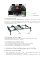
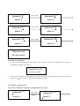
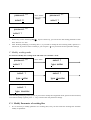
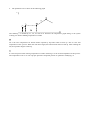
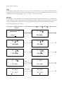
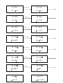
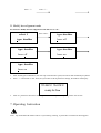
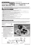
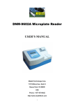
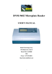
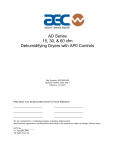
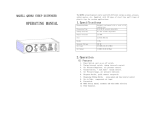
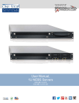
QK-IR2005
BGA/SMD Rework System
User’s Manual
Thanks for purchasing our IR BGA/SMD Rework System. The system is exclusively designed for reworking
and soldering SMD component. Please carefully read this manual before operating the system. Store this
manual in a safe, easily accessible place for future reference.
1. Description
This QK-IR2005 system adopts micro-processor control and infrared sensor technology to do soldering and desoldering to surface mount components safely and accurately. It meets the high technical demands of modern
electronic industry, and is one of the most valued electronic equipments in this field.
The QK-IR2005 Rework System adopts micro-processor control and infrared sensor technologies. It has the
precision non-contact infrared temperature sensor for de-soldering parts and the middle wavelength infrared
heater. The soldering process is under the monitoring of non-contact infrared sensor and optimum control of
process can be achieved at any time. QK-IR2005 has 1500W heating power, suitable for applications of big as
well as small IC components and lead-free applications. Closed-loop temperature control ensures even heat
distribution and appropriate peak temperature for lead-free soldering.
The middle-wavelength infrared heater of QK-IR2005 has a well-proportioned and safe heating and power and
flexibleness necessary for the system, so it can also deal with some PCBs with big thermal capacity and other
high temperature situation (lead-free soldering) easily. The adjustable aperture under the infrared radiator can
protect the adjacent components (which are sensitive to the temperature) on PCB from being heated. No need
for nozzles.
The temperature during the soldering process can be calibrated and measured openly. In other words, you can
press the calibrating key to record the melting point temperature while the solders melts viewed by eye. QK-IR
2005 has 10 types working modes available, with parameters in each mode can be modified by programmable
temperature control. Operations of IR, as well as the setting of parameters are manipulated by the outside
keyboard.
The use of re-flow process camera supplies the critical optical information to judge the melting situation of
solder during the whole soldering and de-soldering process.
Besides, the QK-IR2005, which can also cool the PCB efficiently, together with the intelligent lead-free &
digital calibrating soldering station is an ideal soldering tool for any professional user.
2. Specification and Technical Parameter
2.1 Specification
1.Max Power
1600W (Max)
2.Power of bottom preheating
2*400W (Infrared ceramic heating plate)
3.Power of top heating
4*180W (Infrared heating tube, Size: 60×60mm)
4.Wavelength of IR radiator
2~8µm Approx
5.Other Power consumption
15W
6.Preheating time of bottom IR radiator
90s Approx (Size: 135×250mm)
7.Adjusting rang of top IR radiator
20~60mm
8.Heating time of top IR radiator
Approx 10s (Room Temperature~230℃)
9.Vacuum pump
12V/300mA, 0.05
10.Bottom cooling fan
12V/90mA 12CFM (crosscurrent fan)
11.Top cooling fan
12V/90mA 15CFM
12.Laser alignment tube
3V/30mA (2 pcs)
13.LCD display screen
Size: 65.7×23.5mm 16×2 character
14.Soldering Iron
Intelligent digital display lead free soldering iron
15.Power of soldering iron
60W
16.Communication
standard RS-232C (link with PC)
17.Keyboard
8 buttons
18.Upward and downward movement motor
24VDC/100mA
19.Upward and downward movement range
93mm
20.Infrared Temperature sensor
0~300℃ (Testing range)
21.Outside K type sensor
(Optional)
22.Dimension
33×38×44 (cm)
23.Weight
13Kg
Note: When purchasing the equipment, please point out the work voltage.
2.2 Technical Data
TL: Melting temperature of solder
T1: Heat preservation starting temperature of reflow soldering
T2: Heat preservation ending temperature of reflow soldering
T3: Peak value temperature of soldering and de-soldering
T0: Valve temperature: The lowest temperature of bottom heater when top heater heats ups. T0<TB
TB: The set temperature of bottom heater
Tb: The real time temperature value of bottom heater
Tc: The real time temperature value of top heater
TS: Heat preservation time from T1 to T2
The QK-IR2005 Rework System has ten working modes and its parameter can be changed according to
demand. Concrete setting as the following:
0. T1=100℃、TS=60s、T2=140℃、T3=200℃、TL=183℃、TB=80℃、T0=60℃
1. T1=100℃、TS=60s、T2=150℃、T3=200℃、TL=183℃、TB=80℃、T0=60℃
2. T1=100℃、TS=100s、T2=160℃、T3=200℃、TL=183℃、TB=80℃、T0=60℃
3. T1=100℃、TS=100s、T2=170℃、T3=200℃、TL=183℃、TB=80℃、T0=60℃
4. T1=110℃、TS=60s、T2=140℃、T3=210℃、TL=183℃、TB=100℃、T0=60℃
5. T1=110℃、TS=60s、T2=150℃、T3=210℃、TL=183℃、TB=100℃、T0=60℃
6. T1=110℃、TS=100s、T2=160℃、T3=210℃、TL=183℃、TB=100℃、T0=60℃
7. T1=110℃、TS=100s、T2=170℃、T3=210℃、TL=183℃、TB=100℃、T0=60℃
8. T1=100℃、TS=100s、T2=140℃、T3=220℃、TL=183℃、TB=100℃、T0=60℃
9. T1=100℃、TS=100s、T2=150℃、T3=220℃、TL=183℃、TB=100℃、T0=60℃
3. Product Picture
Movement arm
Vacuum suction tube
Top IR heater
Top cooling fan
Lead free iron
Keyboard
Bottom IR heater
Bottom cooling fan
Iron holder
4. Safety Instructions
Note: For safety of system and operator, please read this manual carefully before operating the unit.
Please note that the unit is suitable for soldering and de-soldering of electronic components.
Note: Top and bottom IR radiator will be very hot during working, so explosive and combustible object or gas
and solvent is strictly prohibited in working areas, also please don’ touch the hot housing parts
Note: The laser alignment device includes a secondary laser device, so don’t see the laser bean directly.
Note: When the system happens trouble and needs maintenance, it should be carried out by an experienced and
authorized dealer.
The unit has high voltage and unauthorized repair is not recommended.
5. Setting–up and connection before using
5.1 Check the equipment
Please check whether all the following parts are complete and good.
* Basic parts of QK-IR2005 combined with intelligent lead free soldering station.
* IR keyboard
* Power cord
* Intelligent lead free soldering station and iron holder.
* PCB movement fixture (optional)
* QK-IR2005 operation manual
Please contact with agent immediately if any part above is damaged or missed.
Note:
Top and bottom IR radiator will be very hot during working, so explosive and combustible object or gas and
solvent is strictly prohibited in working areas, also please don’ touch the hot housing parts
5.2 Place the equipment
Unwrap the packing of the unit, then take it out and put it on the solid level worktable.
5.3 Adjustment function of parts
* Adjust the aperture system
The aperture system of IR radiator on the top of equipment can be adjust from 20×20 (mm) to 60×60 (mm)
by two adjustment knobs. Unscrew the knob before adjusting, and adjust the window size, then screw down the
knob. The scale “2” on the housing means 20mm and “3’ means 30mm, other scale is similar. For example, if
you want to adjust it to 50×50(mm), adjust two knobs to the scale of “5” and screw down them.
Note:
Adjusting the aperture system can protect the adjacent components on the PCB from being heated. But, when
the aperture system is adjusted to small size, the top IR radiator will become very hot, so it’s necessary to
increase the size appropriately to avoid being cut off of the safety switch on top IR radiator.
Scale
Adjustment knob
* PCB movement fixture (optional)
If the QK-IR2005 is used without QK-PL2005 precision placement system, we suggest you use PCB
movement fixture. Its height is adjustable by turning four feet. Four locknuts can lock PCB to prevent it from
moving. Both PCB movement fixture and top IR radiator is on the same level worktable. It is necessary to give
the correct working distance of 40mm.
Locknut
shore
5.4 Connect parts and power supply
* Please check whether the voltage power accords with the rating voltage on the equipment nameplate.
* Please check whether switches are turned off. (Set to “0”)
* Connect Power cord to the power socket behind equipment.
* Connect keyboard to the keyboard socket behind equipment.
* Connect intelligent lead free soldering iron to the soldering iron socket behind equipment.
* If need, connect K type sensor (optional) to the sensor socket behind equipment.
After all these steps, insert power plug into power socket, and switch on power.
6. Instructions of keyboard function and parameter setting
6.1 Instructions of keyboard buttons
A. During selecting working flow period, “↑” and “↓” keys are used for controlling the moving
upward or downward of cursor and increase or decrease of number.
During the soldering or de-soldering period, also top IR heater haven’t yet started to heat up, key “↑” and
key “↓are used for controlling movement upward or downward of top IR heater. That is to say, during
movement upward and downward of top IR heater, after pressing the key “BEGIN”, “↑” and “↓” keys
make the top heater stop at a proper position.
B. Under the standby condition, if the cooling fan have already drawn back, press “↑” and “↓” keys to make
the top IR heater move up and down.
C. Under the standby condition and the top IR heater is at top position, press “ALIGN” key, the cooling fan (it
has laser alignment device inside) will hold out or draw back. When cooling fan completely holds out, the
laser alignment device will switch on automatically. After the cooling fan has held out, if you double click
“ALIGN” key, the cooling fan will be on or off.
D. Function of “SET” key: Make the BGA-IR enter parameters setting mode and cursor move a step forward.
E. Function of “EXIT” key: During the setting mode, make BGA-IR cursor exit until exiting the setting mode;
During the soldering or de-soldering period, make BGA-IR exit operation.
F. Function of “BEGIN” key: During the standby condition, make BGA-IR get into soldering or de-soldering
situation.
G. Function of “CALTL” Key: During the soldering or de-soldering process, when the temperature increase
from T2 to T3, press this key, the current temperature will multiply a coefficient to make TC=TL,
calibrating TL. After the flow has finished and come back to initialization, it will save the coefficient.
H. Function of “CALT3” Key: During the soldering or de-soldering process, when the temperature increase
from T2 to T3, press this key, make the setting value of T3 change to current temperature TC (T3=TC),
calibrating T3. If press the key continuously, top IR heater will not be limited by the setting value of T3,
and it heat up until loose the key.
Note: If press “CALTL” Key again in the initialization situation, the temperature calibration coefficient of TL
comes back to system initialization “1”.
6.2 Parameter settings
Parameter settings order as the follows:
A._password: *** (Password settings)
B._select: 0
(Flow settings, it can modify parameter inside.)
C._type: solder (Working mode settings)
D._laser: off (Laser alignment settings)
E._baud: 19200 (Communication speed settings)
Note:
If want to modify any parameter system, you must input password, otherwise, you can only browse them.
A. Input password
The initial password of system is “000”. At the same time, system also has the omnipotent password “159”. If
you forget the setting password, you can input “159” to make the password of system come back to initial
password “000”.
For instance: Input the initial password “000” of system.
Press “SET”
TC:022˙C Tb:019˙C
ready for flow
Press “SET”
_password: ***
select: 0
Press***
“↓”
password:
Press “SET”
select: 0
Press
“↓”
password:
0**
select: 0
Press “SET”
select: 0
Press
“↓”
password:
00*
password: 0**
password: 00*
select: 0
Press “EXIT”
select: 0
password: 000
select: 0
Welcome you!
Any key return
Finish password inputting:
1. If you want to modify the password, return to above mode to input the new password. If password is
modified successfully, it will show:
Saving Password!
Any key return
2. If you want to modify the next working flow, operate as the following B item; If you don’t want to modify,
please press “↓” key to browse the following parameter settings.
B. Modify working flow
For instance: Modify the working flow and make it become 1 flow.
Press***
“↓”
password:
Step①
select: 0
Press “SET”
Step②
password: ***
select: 0
Press***
“↑”
password:
Step③
select: 0
Press “EXIT”
Step④
password: ***
select: 1
password: ***
select: 1
1. When carry on the forth step (Step④), if press “SET” key, you can browse and modify parameter of this
flow, shown as C-1 item.
2. After finishing modifying of working flow 1, if you want to modify the next working mode, operate as C
item shows; If you don’t want to modify it, yon can press “↓” key to browse the next parameter settings.
C. Modify working mode
For instance: Modify the working mode and make it in “desolder” mode.
Press***
“↓”
password:
Press “SET”
select: 1
Press1“↓”或“↑”
select:
type: solder
select: 1
type: solder
Press “EXIT”
select:
1
type: desolder
select: 1
type: desolder
After finishing modifying working mode, if you want to modify laser alignment mode, operate as D item shows;
if no need to modify it, please press “↓” key to browse the next parameter settings.
C-1. Modify Parameter of working flow
1. If it is necessary to modify parameter of a working flow, first you must select the working flow and then
modify its parameter.
2. The parameters are as shown in the following graph
℃
0
The soldering is decided by T1, T2, T3 and TS. It describes the temperature graph during in the system
working. TL denotes Melting temperature of solder.
T0
T0 is the valve temperature for bottom heater required by top heater when it heats up. Also it is the first
temperature of this process. When the work flow begins, the bottom heater starts to heat up. After reaching the
T0, the top heater begins to heat up.
T1
It is the heat preservation starting temperature of reflow soldering. It is the second temperature of this process.
The temperature rises to T1 with a proper speed the component permits. In parameter modifying, us
keys to set the value of it.
Sense
It is used for choosing the system’s sensor type. Users can also choose K type sensor used for measuring
temperature, besides system’s IR sensor. The signal of chosen sensor will be displayed and used for process
controlling. In parameter modifying, use the “↑” and “↓” key to set the value.
Password
It is used for setting password. It is designed for preventing the equipment unnecessary or non-authorized
change. When it is set to “000”, the password protecting is useless. The password is used for all flows and it
can be useful and useless in each flow. The system requires inputting correct password before any change.
Using of password refer to 6.2 A item.
For instance : Modify parameter of 1 flow and make T1=110℃, T2=160℃, TB=90℃. (1 flow has been
selected)
Press***
“SET”
password:
Press “SET”
_T1:
select: 1
TS: 060s
Press “SET”
T1: 100℃
Press “↑”
TS: 060s
Press “EXIT”T1:
TS: 060s
T2: 150℃
110℃
TS: 060s
Press “↓”
TS: 060s
Press “SET”
TS: 060s
T1: 100℃
TS: 060s
Press “SET”
T1: 110℃
_T1: 110℃
Press “↓”
100℃
T1: 100℃
_TS: 060s
Press “SET”
TS: 060s
T2: 150℃
TS: 060s
Press “↑”
Press “SET”
T2: 150℃
Press “EXIT”
TS: 060s
T2: 160℃
Press “↓”
T2: 160℃
T2: 160℃
Press “↓”
Press “↓”
Press “SET”
Press “SET”
TL: 183℃
TB: 090℃
Press “↓”
TB: 090℃
TB: 090℃
Press “↓”
TL: 183℃
TB: 080℃
TB: 080℃
Press “EXIT”
TL: 183℃
T3: 200℃
TL: 183℃
TB: 080℃
TL: 183℃
Press “↑”
TS: 060s
T2: 160℃
T3: 200℃
Press “SET”
TL: 183℃
TS: 060s
TL: 183℃
TB: 090℃
Press “↓”
T0: 060℃
T0: 060℃
unit:℃
unit:℃
sense: K
sense: K
type: solder
Press “↓”
Press “↓”
D. Modify laser alignment mode
For instance: Modify the laser alignment mode and set it to “on”.
select:Press
1 “↓”
Press “SET”
type: desolder
“↓”或“↑”
type: Press
desolder
laser: off
type: desolder
laser: off
Press “EXIT”
type:
desolder
laser: on
type: desolder
laser: on
1. After finishing the modification, the next step communication speed, will not be able modified by keyboard.
2. Press “↓” and “EXIT” to exit. Now, the system has saved all parameter settings, IR window will display:
TC:022˙C Tb:019˙C
ready for flow
3. After all parameters have been selected, press “BEGIN” key and the system perform the set flow.
7. Operating Instruction
Note: Top and bottom IR radiator will be very hot during working, so please don’ touch the hot housing parts.
Note: The laser alignment device includes a secondary laser device, so don’t see the laser bean directly.
7.1 Instruction of soldering operation (Switch on the system’s power)
1. Turn on power switch of each part.
2. Fix aligned PCB on the top of the bottom heater and make the soldered component between top heater and
bottom heater. The position is easy to be measured with laser alignment device. The right position should
make the red laser point in the center of component. The component which to solder on the PCB have been
aligned before PCB is fixed. Suggest to use the QK-PL2005 precision placement system.
3. Adjust aperture system, and et a proper window size.
4. Select parameter with keyboard. (Refer to parameter settings instructions of 6.2)
A. Input password ”000”
B. Select the required flow, if need to modify, perform relevant operation.
C. Select “solder” working mode.
D. Select “IR” laser alignment mode.
E. No change to communication speed, and press “↓” and “EXIT” key to exit. IR window shows:
TC:022˙C Tb:019˙C
ready for flow
F. Press “BEGIN” and the system start to work, perform content of selected flow.
5. IR window will show a series of setting temperatures during working. Indicate when it reaches T0, T1, T2,
T3 and TL.
6. If you see the solder has melted down (It is watched with IR camera and LCD), you can press “CALTL”
Key to calibrate temperature of TL to adjust the display temperature to liquid temperature TL.
7. When the temperature reaches TL, there will be a sound signal.
8. When the temperature reaches T3, the process is finished and sound signal will change to a unvarying
sound, and the system will not heat up anymore.
9. The system can perform a series of function action during working.
A. After press “BEGIN” key, the top heater move downwards near to bottom.
B. After the system sounds unvaryingly, the top heater move upwards and cooling fan spread out to blow
cooling wind.
C. After 80 seconds, the cooling fan stop blowing, and the soldering process has been finished.
10. The cooling fan stop work and the whole process has been finished.
7.2 Instruction of de-soldering operation (Switch on the system’s power)
1. Turn on power switch of each part.
2. Fix the PCB on the top of bottom heater and make the de-soldered component between top heater and
bottom heater. The position is easy to be measured with laser alignment device. The right position should
make the red laser point in the center of component and the suction pad also in center of component.
3. Press the vacuum suction tube to check whether suction pad is in the center of component. (If the
deflection is too much, the tube will not be able to pick up the component.
4. Adjust aperture system, and get a proper window size.
5. Select parameter with keyboard. (Refer to parameter settings instructions of 6.2)
A. Input password ”000”
B. Select the required flow, if need to modify, perform relevant operation.
C. Select “desolder” working mode.
D. Select “IR” laser alignment mode.
E. No change to communication speed, and press “↓” and “EXIT” key to exit. IR window shows:
TC:022˙C Tb:019˙C
ready for flow
6.
7.
8.
9.
10.
11.
12.
13.
14.
15.
F. Press “BEGIN” and the system start to work, perform content of selected flow.
After pressing “BEGIN” key, bottom heater starts to heat up and top heater moves downwards and reach to
bottom.
IR window will show a series of setting temperatures during working. Indicate when it reaches T0, T1, T2,
T3 and TL. When the bottom temperature reaches T0, the top heater begins to heat up.
When the temperature reaches TL, it will give a sound alert automatically (Low frequency).
When the temperature reaches T3, it will also give a sound alert automatically. (Middle frequency)
When the solder has melted down, press the vacuum suction tube to pick up the component.
Press the vacuum suction tube, the vacuum pump start to work and pick up component, then return to
original position. The system stops heating.
The top heater moves upwards and stops at top.
Cooling fan spreads out to blow cooling wind.
30 seconds after the top heater moving upwards, the vacuum suction tube looses component automatically.
After cooling fan blowing cooling wind for 80 seconds, the whole soldering has been finished.
8. Turn off the equipment
Please turn off power switch of each part and pull out power plug when not using it.
9. Equipment Maintenance
Remark:
For ensuring reliable function and maintenance of equipment, please use only parts provided by us.
Note:
After cutting off the power supply, the housing is still very hot, so please don’t use any dangerous or
combustible solvent to clean it.
Clean parts:
Suggest to use dry or wet towel to clean the equipment. Solder on the grid can be cleaned out with hard object.
Replacement of suction pad:
If you want to replace the suction pad, please turn off power, and replace it after he vacuum suction nozzle and
top heater cool down.
Take suction pad out of suction nozzle downwards, and install a new one in opposite direction.
Contact:
Madell Technology Corporation
7372 Walnut Ave. Suite V
Buena Park, CA 90620
USA
http://www.madelltech.com
Distributor: