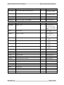
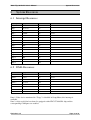
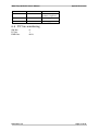
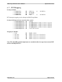
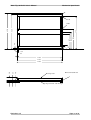
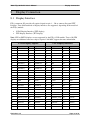
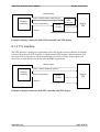
1
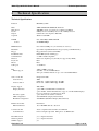
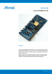
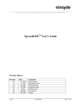
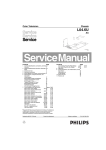
User’s Manual ETE-GLX MSC ETE/ETX Module AMD Geode LX800 Rev. 0.19 November 24th, 2008 Preface Copyright Notice Copyright © 2008 MSC Vertriebs GmbH. All rights reserved. Copying of this document, and giving it to others and the use or communication of the contents thereof, are forbidden without express authority. Offenders are liable to the payment of damages. All rights are reserved in the event of the grant of a patent or the registration of a utility model or design. Important Information This documentation is intended for qualified audience only. The product described herein is not an end user product. It was developed and manufactured for further processing by trained personnel. Disclaimer Although this document has been generated with the utmost care no warranty or liability for correctness or suitability for any particular purpose is implied. The information in this document is provided “as is” and is subject to change without notice. EMC Rules This unit has to be installed in a shielded housing. If not installed in a properly shielded enclosure, and used in accordance with the instruction manual, this product may cause radio interference in which case the user may be required to take adequate measures at his or her own expense. Trademarks All used product names, logos or trademarks are property of their respective owners. Certification MSC Vertriebs GmbH is certified according to DIN EN ISO 9001:2000 standards. Life-Cycle-Management MSC products are developed and manufactured according to high quality standards. Our lifecycle-management assures long term availability through permanent product maintenance. Technically necessary changes and improvements are introduced if applicable. A productchange-notification and end-of-life management process assures early information of our customers. Product Support MSC engineers and technicians are committed to provide support to our customers whenever needed. Before contacting Technical Support of MSC Vertriebs GmbH, please consult the respective pages on our web site at www.msc-ge.com/support-boards for the latest documentation, drivers and software downloads. If the information provided there does not solve your problem, please contact our Technical Support: Email: [email protected] Phone: +49 8165 906-200 Contents 1 General Information............................................................................................ 5 1.1 Introduction .................................................................................................. 5 1.2 Technical Information ................................................................................... 6 2 Module Description ............................................................................................ 7 2.1 Block Diagram .............................................................................................. 7 2.2 CPU and Chipset.......................................................................................... 8 2.3 Memory ........................................................................................................ 8 2.4 Super IO ....................................................................................................... 9 2.5 Ethernet Controller ....................................................................................... 9 2.6 Parallel Busses............................................................................................. 9 2.7 USB Ports .................................................................................................. 10 2.8 IDE Interfaces ............................................................................................ 10 2.9 System Monitor .......................................................................................... 10 2.10 Audio Subsystem .................................................................................... 10 2.11 System Serial Busses ............................................................................. 10 3 BIOS Description .............................................................................................. 11 3.1 SETUP MENUS ......................................................................................... 11 3.1.1 General Menu Navigation ....................................................................... 11 3.1.2 Setup Main Menu.................................................................................... 12 3.1.3 Motherboard Device Configuration Menu ............................................... 13 3.1.4 Memory an Cache Optimization Menu.................................................... 17 3.1.5 System Clock/PLL Configuration Menu .................................................. 17 3.1.6 Power Management Menu ...................................................................... 17 3.1.7 Miscellaneous Configuration ................................................................... 17 3.1.8 Boot Order .............................................................................................. 18 3.1.9 Password Settings .................................................................................. 18 3.2 Network Boot Menu .................................................................................... 19 3.3 BIOS Tools ................................................................................................. 19 3.3.1 Update .................................................................................................... 19 3.3.2 CMOS data ............................................................................................. 19 3.3.3 BIOS Setup Default Data ........................................................................ 19 3.3.4 Force the use of CMOS default data ..................................................... 20 4 Technical Specification .................................................................................... 21 5 Signal and Pin-Out Description ....................................................................... 23 5.1 ET(e) Connector X1 (PCI Bus, USB, Sound) ............................................. 23 5.2 ET(e) Connector X2 (ISA Bus) .................................................................. 26 5.3 ET(e) Connector X3 (VGA, LCD, Video, COMx, LPT/Floppy, Keyboard, Mouse, IRDA) ....................................................................................................... 28 5.4 ET(e) Connector X4 (IDE, Ethernet, Miscellaneous) ................................. 32 6 System Resources ........................................................................................... 35 6.1 Interrupt Resources .................................................................................... 35 6.2 DMA Resources ......................................................................................... 35 6.3 Memory Mapping........................................................................................ 36 6.4 IO Mapping ................................................................................................. 36 6.5 6.6 6.7 6.8 Device Addresses ...................................................................................... 36 I²C bus numbering ...................................................................................... 37 PCI Mapping .............................................................................................. 38 System Serial Buses .................................................................................. 39 7 Mechanical Specification ................................................................................. 40 8 Display Connection .......................................................................................... 42 8.1 Display Interface......................................................................................... 42 8.1.1 LVDS Interface ....................................................................................... 43 8.1.2 TTL Interface .......................................................................................... 45 8.1.3 Power Switch .......................................................................................... 46 8.1.4 Signals ET(e) Module <-> TFT Display with TTL Signalling ................... 47 8.1.5 Signals ET(e) Module <-> TFT Display with LVDS Signalling (18 Bit) .... 48 8.2 Resolution and Timings .............................................................................. 49 9 Power Management and Power Control ......................................................... 50 10 External ports COM3 and COM4 ................................................................. 51 11 Windows Installation Hints ......................................................................... 51 12 Thermal management, Environment .......................................................... 51 13 Post Codes ................................................................................................... 51 MSC ET(e)-GLX CPU User's Manual 1 General Information General Information 1.1 Introduction The MSC ET(e) CPU modules are compatible to standard ETX modules which are available on the market. These CPU modules are standardized in terms of system interfaces and mechanical dimensions. An ET(e) module typically includes the CPU, the chipset, memory, video controller, Ethernet controller, BIOS flash, sometimes flash disk (e.g. CompactFlash), as well as EIDE-, floppy-, keyboard- and mouse controller. ET(e) modules are designed with different CPU cores. Today the range from 266MHz x86 based 586 core (e.g. National Geode GX1 processor) to 1.8 GHz Pentium M core is available. This way, customers of embedded PC modules are offered scalable and price-optimized solutions. Use a complete PC-compatible system simply as a super-component. In application systems, the ET(e) module is mounted on a baseboard by means of four 100pin SMD connectors. Via these connectors the standard PC interface signals for PCI- and ISA-Bus, USB, EIDE, floppy/LPT, COM, keyboard, mouse etc. as well as the power supply are provided. Because of the mechanical and electrical standardization of the ET(e) modules, the system of ET(e) module and baseboard is scalable. The flat design makes allows realizing very compact systems. The baseboard provides all application-specific functionalities and is typically a custom specific board developed by our customer. MSC also offer the service to design and produce baseboards for your application. Connect MSC for more information. For evaluation and test MSC offers a special baseboard, a kind of motherboard, including the standard PC interfaces as well as additional connectors and features. The board is referred to as MSC ET(e)-MB-ATX and provides the following features: • four PCI Slots • three ISA Slots • two EIDE channels • one CompactFlash connector on secondary EIDE channel • two interfaces for floppy disk drives • RJ45 connector for Ethernet • four USB interfaces • PS/2 connectors for keyboard and mouse • two parallel interfaces • four serial interfaces • 15pin DSUB connector for VGA • analogue Video Out interface • FPDDC (compatible to JILI (JUMPtec Intelligent LVDS Interface)) Revision 0.1A Page 5 of 53 MSC ET(e)-GLX CPU User's Manual • • • • • • General Information flex foil connector for LCD interface three 3.5mm connector for microphone, line-in and line-out two connectors for powered audio signals one IrDA interface 16 bit general purpose Data-IO Onboard Port80h display Use the MSC ET(e)-MB-ATX board as design reference for your baseboard. Ask MSC for the schematics and additional information. The schematics are available in PDF and OrCAD format. They are free of charge. 1.2 Technical Information This document is based on the following references: [1] [2] [3] [4] [5] [6] [7] Datasheet AMD GEODE LX Processor Datasheet AMD CS5536 Companion Datasheet Winbond W83627HF Super IO Datasheet Winbond W83626F LPC to ISA Bridge Datasheet Intel 82551 Fast Ethernet Controller PCI Bus Specification ISA Bus Specification For design information or any questions ask MSC or join our web site www.msc-ge.com Revision 0.1A Page 6 of 53 X2 ISA W83626 LPC to ISA COM1 COM2 IrDA LPC Bus BIOS Flash Keybd Mouse Super I/O + 5V +3,3V GEODE LX800 (BGA 481) up to 500MHz optional LVDS (ISA) CRT StandBy Power DDR-SDRAM SO-DIMM max. 1024 MB Floppy / LPT (incl. WatchDog & Monitor Functionality) MSC ET(e)-GLX CPU User's Manual LVDS/ TTL Module Description I/O Voltage ISA Bus 2 Core Voltage Keyboard/Mouse, Floppy or LPT) 2.1 Block Diagram Revision 0.1A X3 (CRT, LVDS/DFP, TVout, COM1/2, IrDA, Videoport LPC GEODE CS5536 Companion EIDE UBat Power Ctrl I2C USB 0 .. 3 PCI Audio PCI Audio CODEC Compact Flash Typ 1 X1 (PCI, 4 x USB, Audio) LAN Controller 10/100MBit MSC-ETe / GLX Page 7 of 53 Module Description X4 (Speaker, EIDE, Batt, I2C, PwrCtrl, PwrMgmt, LAN) PCI MSC ET(e)-GLX CPU User's Manual Module Description 2.2 CPU and Chipset The MSC ET(e)-GLX module is based on the AMD processor Geode LX [email protected]. This processor supports the MMX and AMD 3DNOW! instruction sets. The CPU core supports different clock rates up to 500 MHz. The Northbridge is integrated in the processor chip while the Southbridge, the AMD CS5536 (called Companion), with additional functionality is a separate device. CPU features: • Low Power CPU with power consumption (1.6W typical at 500 MHz) • CPU core with MMX and AMD 3DNOW! instruction set • 64 KByte Level 1 Data-Cache, 64KByte Level 1 Instruction-Cache • 128 KByte configurable Level 2 Cache • ICE interface • Floating point unit (FPU) • Memory Management Unit (MMU) • PCI bridge • High performance 2D Graphics controller • Display controller • DDR SDRAM controller • APM and ACPI Management Refer to [1] for detail information Companion features: • PCI to LPC Bridge • System Management Bus controller • GPIO interface • 8259A compatible interrupt controller • 8254 compatible timers • 8237 compatible DMA controller • Bus-mastering IDE controller (1 channel, 2 devices) • AC97 codec interface • USB 2.0 serial interface Refer to [2] for detail information 2.3 Memory DDR-SDRAM The module operates with one DDR SDRAM SO-DIMM module. Supported are 2.5 Volt modules with up to 1024 Mbyte. CompactFlash One CompactFlash socket for CompactFlash Type I cards, connected as master device. Revision 0.1A Page 8 of 53 MSC ET(e)-GLX CPU User's Manual Module Description BIOS Flash The GLX module supports 4MBit Firmware Hubs. 2.4 Super IO The module uses the Super IO chip Winbond W83627HF with the following features: • Floppy Disc Controller (FDC) • Two 16550 compatible UARTs • IRDA Infrared Interface • Parallel Port (ECP, EPP compatible) • APM controller • Keyboard/Mouse controller • Real Time Clock • Watchdog Timer Refer to [4] for information in detail 2.5 Ethernet Controller The Ethernet interface was built with the Intel 82551 Ethernet controller. Refer to [5] for information in detail. 2.6 Parallel Busses The MSC ET(e)-GLX module provides two parallel busses, the PCI bus and the ISA bus. PCI Bus The PCI bus meets the PCI 2.2 specification (refer to [6] for information in detail). The PCI bus implementation has 32Bit buswidth at 33MHz clock rate. The ET(e)-GLX module supports up to 4 external bus master. Note: The PCI bus on the Geode LX module is not 5V TTL tolerant. Refer to [6] for information in detail. ISA Bus The ISA bus meets the ISA bus specification with some restrictions: ISA Bus Masters are not supported and 16 Bit wide I/O and Memory R/W accesses are split into two consecutive 8 Bit wide accesses. Refer to [4] and [7] for information in detail. Note: The ISA bus signals are generated by the Winbond 83626 LPC to ISA Bridge. Revision 0.1A Page 9 of 53 MSC ET(e)-GLX CPU User's Manual Module Description 2.7 USB Ports The USB Ports are over-current protected. All four USB ports are supported by the GLX module. The USB ports meet the USB2.0 specification. Refer to [2] for information in detail. 2.8 IDE Interfaces One enhanced IDE port with two devices (one master, one slave) is supported. Refer to [2] for information in detail. Do not connect to primary and secondary IDE port at the same time. Both ports of the ET(e) connector are led to the same IDE port on the module. If the on-board CF-Card connector is used, then connect the slave device (CF-Card is master) to your baseboard’s secondary IDE-connector. If two external IDE devices are used, connect both devices to either your baseboards primary or secondary channel. Do not use one device on primary, one device on secondary channel. Currently boot is only possible from IDE master device if two devices (one master, one slave) are connected. 2.9 System Monitor The module is monitored by the Winbond W83627HF Super-IO. Refer to [3] for information in detail. Currently, four supply voltages are monitored • VCC CORE (1.2 V for the LX800) • VCC CORE STANDBY (1.2 V for the LX800) • VCC 3V3 (3.3 V) • VCC MEM (2.5 V) Additionally, the monitoring of the CPU die Temperature and board temperature is implemented. 2.10 Audio Subsystem The audio subsystem of the companion chip is AC97 compliant and works together with AC97 codec LM4549 from National Semiconductor. Refer to [2] for information in detail. 2.11 System Serial Busses The module has 4 serial buses (like I2C Bus). • • • • SM Bus (System Management Bus, provided by companion SM Bus controller) DDC Bus (Data Display Channel, provided by companion) FP DDC Bus (Flat-panel Data Display Channel, provided by companion) I2C Bus (General purpose serial bus, provided by W83627 Super IO) Revision 0.1A Page 10 of 53 MSC ET(e)-GLX CPU User's Manual 3 BIOS Description BIOS Description 3.1 SETUP MENUS To enter Setup: Press the F1 key while booting the system. 3.1.1 General Menu Navigation To navigate within menus use the following keys: Key Function Up Arrow Highlight the item above the currently highlighted item. If on the top item will highlight the last item. Down Arrow or Highlight the item below the currently highlighted item. If on the Space bottom item will highlight the top item. Left arrow Highlight the item to the left of the currently highlighted item. If there is no item directly to the left, the rightmost item on the previous line is highlighted. Right Arrow Highlight the item to the right of the currently highlighted item. If there is no item directly to the right, the leftmost item on the next line will be highlighted. Enter or a Select the currently highlighted item. This will cycle through the st highlighted 1 Choices for an item or bring up an entry box for direct entry of a character of an value depending on how the item is configured. item F1 Will display a Long Help for the currently highlighted item. It there is no Long Help for the item the Short Help will be displayed. Escape Will close the current menu and return to the previous menu. If there is no previous menu, this key will do nothing Revision 0.1A Page 11 of 53 MSC ET(e)-GLX CPU User's Manual BIOS Description 3.1.2 Setup Main Menu When entering Setup this is the first menu displayed. In the following all sub menus are described tabular to get a better overview. Revision 0.1A Page 12 of 53 MSC ET(e)-GLX CPU User's Manual BIOS Description 3.1.3 Motherboard Device Configuration Menu Entering Motherboard Device Configuration Menu display the following sub menu items. Item Options Comment Drive Configuration Sub Menu Set configuration for hard drive and floppy devices LPC Card Devices Sub Menu Set configuration for Onboard Super I/O devices External Super I/O Configuration Sub Menu Set configuration for External Super I/O devices Video and Flat Panel Configuration Sub Menu Set Video and Flat Panel Configuration PCI Configuration Sub Menu Set PCI Bus Configuration Network Configuration Sub Menu Set Network Configuration Themal Configuration Sub Menu Read current CPU temperature Return to Main Menu Upper level menu Go back into Main Menu Enter “External Super I/O Configuration” requires a base board with external SMSC C669 SIO 3.1.3.1 Drive Configuration Menu Item Options Comment IDE BIOS Support Enable Disable Enable/Disable INT 13h interface in BIOS for IDE drives 80-Conductor Cable Sense None Force 40 Force 80 GPIO 05 No cable sense (leads to 40 conductor cable) leads to 40 conductor cable leads to 80 conductor cable auto detect cable DMA/UDMA BIOS Support Enabled Disabled Enable DMA BIOS support Disable DMA BIOS support Force mode for Drive AUTO … Automatically select mode Force selected mode Floppy Bios Support Enable Disable Enable/Disable all floppy support External Floppy Enable Disable Enable/Disable External floppy Controller CD-ROM Boot Bios Support Enable Disable Enable/Disable CD-ROM Boot option Enabling “Floppy Bios Support” only enables the BIOS support for floppy devices. Using a floppy requires a correct setting of LPT/FLPY# to low level (LPT or Floppy Interface configuration input). Enabling “External Floppy” requires a base board with external SMSC C669 SIO. For some USB memory sticks it may be necessary to enable “Floppy Bios Support” to make “Boot from USB” available. Revision 0.1A Page 13 of 53 MSC ET(e)-GLX CPU User's Manual BIOS Description 3.1.3.2 LPC Card Devices Item Options Comment Serial Port 1 Serial Port 2 Disabled 3f8h, 2f8h, 3e8, 2e8h IRQ 3, 4, Disabled Configure the onboard UART Parallel Port A Disabled 378h 278h 3BCh Configure the onboard Parallel Port Address MODE Compatible PS/2 Bi-directional EPP 1.7 EPP 1.9 ECP Configure the mode of the onboard Parallel Port IRQ Disabled IRQ 5 IRQ 7 IRQ 9 IRQ 10 IRQ 11 Configure the IRQ Used by the onboard Parallel Port DMA None Channel 1 Channel 3 Configure the DMA channel used in ECP mode ISA Bus IRQ Menu ISA disabled Configure each IRQ as ISA or disabled, IRQs used by other devices in BIOS setup are grayed out Watchdog Cyclic Timeout Minutes to wait (0=disable, 1-255) Enable/disable watchdog and set cyclic timeout (minutes). Setting 0 disables Watchdogtimer. Every other value sets delay to n minutes starting with next boot. Watchdog Start Delay Minutes to wait (1-255) 0 : same as “Watchdog Cyclic Timeout” Enable/disable watchdog initial timeout (minutes). This timeout is the value for the first WDT timeout in system. Setting timeout to 0 results in delay value is used for timeout. Every other value sets timeout to n minutes starting with next boot. Enabling “Parallel Port A” only enables the chipset device. Using the parallel port requires a correct setting of LPT/FLPY# to high level (LPT or Floppy Interface configuration input). If you use an IRQ for the ISA bus you must not use this IRQ for any PCI interrupt. 3.1.3.3 External Super I/O Configuration Menu Item Options Comment Serial Port C Serial Port D Disabled 3f8h, 2f8h, 3e8, 2e8h IRQ 10, 11, Disabled Configure the external UART Parallel Port B Disabled 378h 278h 3BCh Configure the onboard Parallel Port Address MODE Printer Mode SPP EPP 1.9 and SPP EPP 1.7 and SPP ECP ECP and EPP 1.9 Configure the mode of the onboard Parallel Port Revision 0.1A Page 14 of 53 MSC ET(e)-GLX CPU User's Manual BIOS Description ECP and EPP 1.7 IRQ IRQ 5 IRQ 7 Configure the IRQ Used by the onboard Parallel Port DMA None Channel 2 Channel 1 Configure the DMA channel used in ECP mode Enter “External Super I/O Configuration” requires a base board with external SMSC C669 SIO 3.1.3.4 Video and Flat Panel Configuration Menu Item Options Comment Internal Adaptor Mode Disabled Primary Secondary Configures the primary display if using a PCI VGA adapter Video Memory 2.0MB - 254MB Select the amount of memory to reserve for video Output Display CRT Flat Panel TV Output Panel and CRT Select display type Driver controls init Enabled Disabled If enabled OS driver has to initialize graphics HW Flat Panel Configuration … Configures the flat panel 3.1.3.5 Flat Output Configuration Item Options Comment Type EDID 2.0 Read display data from eeprom, EDID 2.0 preferred. Read display data from eeprom, EDID 1.3 preferred. Use predefined settings. EDID 1.3 TFT Resolution 320x240 640x480 800x600 1024x768 1152x864 1280x1024 1600x1200 Configures the output resolution Data BusType 9-24 bits, 1ppc The only data bus type Refresh Rate 60 Hz 70 Hz 72 Hz 75 Hz 85 Hz 90 Hz 100 Hz HSYNC Polarity Active low Active high The horizontal synchronization pulse polarity VSYNC Polarity Active low Active high The vertical synchronization pulse polarity LP Active Period Active only Free running Data enable Revision 0.1A Page 15 of 53 MSC ET(e)-GLX CPU User's Manual SHFCLK Active Period Active only Free running BIOS Description How to use pixel clock When using the BIOS in the flat panel EDID mode it is recommended to set the TFT data to the expected resolution to get a display even if there are no EDID data available. 3.1.3.6 PCI Configuration Menu Item Options Comment PCI INTA# Disable, IRQ 1, IRQ 3, IRQ 4, IRQ 5, IRQ 6, IRQ 7, IRQ 9, IRQ 10, IRQ 11, IRQ 12, IRQ 14, IRQ 15 Enable/Disable INTA# to IRQ steering PCI INTB# Same as above Enable/Disable INTB# to IRQ steering PCI INTC# Same as above Enable/Disable INTC# and internal USB to IRQ steering PCI INTD# Same as above Enable/Disable INTD# and on-board LAN to IRQ steering USB 2.0 OHCI Enable Disable Enable/Disable OHCI PCI header USB 2.0 EHCI Enable Disable Enable/Disable EHCI PCI header USB Legacy Support Enable Disable Enable/Disable USB Legacy Support after BIOS starts booting to OS USB 2.0 Overcurrent Reporting Disable Enables/Disables reporting via USB registers 3.1.3.7 Network Configuration Menu Item Options Comment Network boot Enable Disable Enable/Disable network boot 3.1.3.8 Thermal Configuration Menu Item Options Comment Current CPU Temperature Current Ambient Temp. Current Board Temperature … Every key return reads the current temperature Revision 0.1A Page 16 of 53 MSC ET(e)-GLX CPU User's Manual BIOS Description 3.1.4 Memory an Cache Optimization Menu Item Options Comment Cache Enable Enable Disable Enables/Disables the memory cache Cache Mode Write-Back Write-Through Select the memory cache mode Cache Allocate Enable Disable Memory Optimization Auto for information only CAS Latency Auto for information only Refresh Rate Auto for information only Memory Latencies Auto for information only 3.1.5 System Clock/PLL Configuration Menu Item Options Comment Clock Determined By Manual Settings Usage of below defined PLL settings CPU Multiplier 7-15 Multiplier * 33Mhz = CPU Speed GeodeLink Multiplier 7-10 Multiplier * 33Mhz = Geode Link Speed 3.1.6 Power Management Menu Item Options Comment BIOS PM at Boot Disabled Enabled Turns on legacy PM before booting OS APM Available No Yes APM interface available for use ACPI Available No Yes ACPI interface available for use S1 Clock On Off Controls the external clock generator in S1 CPU Clock Gating Enabled Disabled Set to Enabled for power saving Chipset Clock Gating Enabled Disabled Set to Enabled for power saving 3.1.7 Miscellaneous Configuration Item Options Comment Splash Screen Enable Disable Enable/Disable display of splash screen Clear Splash Screen Enable Disable Enable/Disable clearing of splash screen after display (if enabled) Splash Screen Timeout Milliseconds to wait (0=no wait, 1-65535) Enable/Disable splash screen delay/timeout after display (if enabled) Revision 0.1A Page 17 of 53 MSC ET(e)-GLX CPU User's Manual BIOS Description Display text Enable Disable Enable/Disable display of all BIOS output texts Summary Screen Enable Disable Enable/Disable display of summary screen Summary Screen Timeout Milliseconds to wait (0=no wait, 1-65535) Enable/Disable summary screen delay/timeout after display (if enabled) Power Button Disabled Enabled AT board compatible Enable: Use ACPI Mode 4 second soft off. Disable: ACPI Mode is disabled after power on. AT mode: Power button is completely disabled after power on. You have to remove power to activate the new setting. AC Beeper Disabled Enabled CMOS Option Configuration 0-20 (0=disabled) Enables/disables PC speaker Number of failed boots before reset CMOS data. After a number of failed boots the CMOS data becomes resetted to BIOS default values 3.1.8 Boot Order Item Options Comment 1. None Floppy Disk USB Floppy Disk Hard Drive Master Hard Drive Slave CD-ROM Drive USB Hard Drive/Flash USB CD-ROM Drive Specifies first boot device 2. Same as above Specifies second boot device 3. Same as above Specifies third boot device 4. Same as above Specifies fourth boot device 5. Same as above Specifies fifth boot device 6. Same as above Specifies sixth boot device 3.1.9 Password Settings Item Options Comment Use Setup Password Disabled Enabled Disable / Enable Call for Password Edit Password Password characters ( 1-64) Type in password two times Revision 0.1A Page 18 of 53 MSC ET(e)-GLX CPU User's Manual BIOS Description 3.2 Network Boot Menu If network boot is enabled in Bios Setup, it can be configured by pressing “CTRL – S” during POST. A network boot menu “Intel® Boot Agent FE v4.1.16” is shown with the following settings: Item Options Comment Network Boot Protocol PXE Only this setting available Boot Order Try network first, then local drives Try local drives first, then network Try network only Try local drives only Select the position of the network boot.in the boot order. Show Setup Prompt Enable Disable Enables/disables if “Please press CTRL – S to enter …” sentence is shown.. Setup Menu Wait Time Seconds to wait (0-5 seconds) Select how long the sentence “Please press CTRL – S to enter …” is shown. Press Space to change the highlighted value. Press enter to highlight the next option. Press ESC to leave menu without changes. Press F4 to save configuration. 3.3 BIOS Tools There are some useful tools for BIOS update and cmos data handling. All tools need a DOS like MS DOS 6.22 with memory manager himem.sys to run properly. 3.3.1 Update Flashrom.com is used to update the contents of the flash ROM of your MSC ET(e)-GLX with a new version of the Bios. Example of usage: flashrom /sFFFC0000 <file_name> After successfully flashing the new bios contents, you must perform a power cycle. During the first boot you have to go into the BIOS setup and load bios defaults. 3.3.2 CMOS data To save current CMOS data for later usage you may use the tool “CMOS.EXE”. Saving : cmos –s <file_name> Restoring : cmos –r <file_name> 3.3.3 BIOS Setup Default Data It is sometimes necessary to have special default data used in production BIOS. There is a tool to patch the current setup data to the BIOS file. By using “GlxPatch.exe” the current setup stored in CMOS ram is patched to the BIOS update file “xpress.rom”. There is no other destination possible. The file “xpress.rom” is used from the current directory! Usage : Revision 0.1A Page 19 of 53 MSC ET(e)-GLX CPU User's Manual BIOS Description 1. Update the BIOS : flashrom /sfffc0000 xpress.rom 2. New CMOS data Use BIOS setup to configure the CMOS data. 3. Patch the default data glxpatch Now the file xpress.rom is updated with the new default data. 4. Personalize BIOS Rename file xpress.rom to your preferred file name <file_name> 5. Use the new BIOS flashrom /sfffc0000 <file_name> 3.3.4 Force the use of CMOS default data There are situations when it is useful to have the CMOS ram set with the default data when starting the BIOS. This can be managed from the DOS prompt with the following program call : forcdflt When the BIOS is started the next time it sets the default values to CMOS and E²Prom then boots again. Revision 0.1A Page 20 of 53 MSC ET(e)-GLX CPU User's Manual 4 Technical Specification Technical Specification Technical Specification: Function MSC ET(e)-GLX CPU CPU Speed Cache Chipset Super IO AMD GEODE LX [email protected], BGA481 500 MHz (slower speeds may be configured via BIOS) 64Kbyte Level 1 I, 64Kbyte Level 1 D, 128Kbyte Level 2 CS5536 Geode Companion, BGA208 Winbond 83627HF DRAM Socket max. 1024 MByte DDR SDRAM SO-DIMM 200pin EIDE Interface One enhanced IDE ports (one channel, two devices) Flashdisk Floppy Parallel Interface Serial Interface Infrared Keyboard Mouse USB ports Optional CompactFlash Interface Type I (using one IDE Channel) Floppy Interface (shared with LPT) ECP / EPP (shared with Floppy) 2 x TTL 16550 compatible IrDA 1.0 compliant port (currently not supported by BIOS) PS/2 PS/2 4 x USB 2.0 PCI Master support 32Bit / 33MHz / 3V3only Standard: one external PCI Master with option Arbiter Extension: up to four external PCI Master Video Controller Videomemory Integrated in CPU TBD CRT: max. 1,920x1,440x32 bpp @ 85Hz, LCD: max. 1,600x1,200x32 bpp @ 60Hz Videoresolution Display support Display Interface TV Video signals CRT configuration Flat Panel configuration TFT, CRT option TTL: 18/24 Bit TTL Level Interface option LVDS: 18 Bit LVDS Interface, support of 24 Bit LVDS Displays has to be checked for each display in detail option TV Out onboard TV controller with CRT DDC (Display Data Channel) with FPDDC (Flat Panel Display Data Channel) Ethernet Controller Ethernet Interface Intel 82551 10 or 100 MHz with auto detection Sound Controller Sound Interface AC97 compliant with external Codec LM4549 Line level input/output and Microphone via ETX header Real Time Clock Watchdog Timer SM Bus support yes, companion CS5536 yes, companion CS5536 yes Revision 0.1A Page 21 of 53 MSC ET(e)-GLX CPU User's Manual Technical Specification I2C Bus Systemmonitoring yes Board-Temperature, Voltage Supervision BIOS Sytem BIOS VGA BIOS Boot devices Boot options Power Management USB legacy support USB Floppy Boot Flash Update INSYDE BIOS INSYDE BIOS Floppy, Harddisc, CD-ROM, USB-Stick, Ethernet TBD yes yes yes via Floppy or HDD Supply Voltage Standard Power Supply Voltage Batterie Power Current consumption 5V0DC + 5V0DC, 5% + 3V3DC +0,3V / -0,9V 266Mhz: + 5V, ~1,1A typ, max. ~1,4A 500Mhz: + 5V, ~1,3A typ, max. ~1,8A Current consumption Batterie Power ~ 10uA typ. Temperature Humidity Mechanical Dimension Dimension Thickness (Bottom + Top) Revision 0.1A operation: 0° to 60°C storage: -10° to 85°C operation: 10% to 90% storage: 5% to 95% (non-condensing) 95 x 114 mm (3.7“ x 4.5“) ≤12mm Page 22 of 53 MSC ET(e)-GLX-CPU User's Manual 5 Signal and Pin-Out Description Signal and Pin-Out Description 5.1 ET(e) Connector X1 (PCI Bus, USB, Sound) Signal Description I/O Note VCC Power Supply +5VDC, 5% I external supply GND Power Ground I external supply 3V Power Supply +3V3DC O Do not use externaly N.C. Not connected n.a. Do not connect SERIRQ Serial interrupt request n.c. Not supported Signal Description of PCI Bus Signals I/O Note PCICLK1..4. PCI clock output O REQ0..3# PCI bus request I GNT0..3# PCI bus grant O AD0..31 PCI Adress-/ Databus I/O PCI signals not 5V0 compliant CBE0..3# PCI bus command/byte enables I/O PCI signals not 5V0 compliant PAR PCI bus parity I/O PCI signals not 5V0 compliant SERR# PCI bus system error I/O PCI signals not 5V0 compliant GPERR# PCI bus grant parity error I/O PCI signals not 5V0 compliant PME# PCI bus power management event I/O Not supported LOCK# PCI bus lock I/O PCI signals not 5V0 compliant DEVSEL# PCI bus device select I/O PCI signals not 5V0 compliant TRDY# PCI bus target ready I/O PCI signals not 5V0 compliant IRDY# PCI bus initiator ready I/O PCI signals not 5V0 compliant STOP# PCI bus stop I/O PCI signals not 5V0 compliant FRAME# PCI bus frame I/O PCI signals not 5V0 compliant PCIRST# PCI bus reset O Asserted with power on reset, ext. reset input and CPU reset INTA# PCI bus interrupt A I PCI signals not 5V0 compliant INTB# PCI bus interrupt B I PCI signals not 5V0 compliant Revision 0.1A PCI signals not 5V0 compliant Page 23 of 53 MSC ET(e)-GLX-CPU User's Manual Signal and Pin-Out Description INTC# PCI bus interrupt C I PCI signals not 5V0 compliant INTD# PCI bus interrupt D I PCI signals not 5V0 compliant Signal Description of USB Signals I/O Note USB0, USB0# USB Port 0 I/O USB1, USB1# USB Port 1 I/O USB2, USB2# USB Port 2 I/O USB3, USB3# USB Port 3 I/O Signal Description of Audio Signals I/O SNDL Line-Level stereo output left O SNDR Line-Level stereo output right O AUXAL Auxiliary input A left I AUXAR Auxiliary input A right I MIC Microphone input I ASGND Analog ground of sound controller I ASVCC Analog supply of sound controller I Revision 0.1A Note Page 24 of 53 MSC ET(e)-GLX-CPU User's Manual Signal and Pin-Out Description Pin Signal Pin Signal Pin Signal Pin Signal 1 GND 2 GND 51 VCC 52 VCC 3 PCICLK3 4 PCICLK4 53 PAR 54 SERR# 5 GND 6 GND 55 GPERR# 56 Reserved 7 PCICLK1 8 PCICLK2 57 PME# 58 USB2# 9 REQ3# 10 GNT3# 59 LOCK# 60 DEVSEL# 11 GNT2# 12 3V 61 TRDY# 62 USB3# 13 REQ2# 14 GNT1# 63 IRDY# 64 STOP# 15 REQ1# 16 3V 65 FRAME# 66 USB2 17 GNT0# 18 RESERVED 67 GND 68 GND 19 VCC 20 VCC 69 AD16 70 CBE2# 21 RIRQ 22 REQ0# 71 AD17 72 USB3 23 AD0 24 3V 73 AD19 74 AD18 25 AD1 26 AD2 75 AD20 76 USB0# 27 AD4 28 AD3 77 AD22 78 AD21 29 AD6 30 AD5 79 AD23 80 USB1# 31 CBE0# 32 AD7 81 AD24 82 CBE3# 33 AD8 34 AD9 83 VCC 84 VCC 35 GND 36 GND 85 AD25 86 AD26 37 AD10 38 AUXAL 87 AD28 88 USB0 39 AD11 40 MIC 89 AD27 90 AD29 41 AD12 42 AUXAR 91 AD30 92 USB1 43 AD13 44 ASVCC 93 PCIRST# 94 AD31 45 AD14 46 SNDL 95 INTC# 96 INTD# 47 AD15 48 ASGND 97 INTA# 98 INTB# 49 CBE1# 50 SNDR 99 GND 100 GND Revision 0.1A Page 25 of 53 MSC ET(e)-GLX-CPU User's Manual Signal and Pin-Out Description 5.2 ET(e) Connector X2 (ISA Bus) Signal Description I/O Note VCC Power Supply +5VDC, 5% I external supply GND Power Ground I external supply N.C. Not connected n.a. Do not connect Signal Description of ISA Bus Signals I/O Note SD0..15 ISA Databus I/ O 5V0 signal level, 5V0 compliant SA0..19 ISA Addressbus O SA0..15 : 5V0 signal level SBHE# ISA Byte High Enable O 5V0 signal level BALE ISA Address Latch Enable O 5V0 signal level AEN ISA Address Enable O 5V0 signal level MEMR# ISA memory read O 5V0 signal level SMEMR# ISA memory read in lowest 1MB address range O 5V0 signal level MEMW# ISA memory write O 5V0 signal level SMEMW# ISA memory write in lowest 1MB address range O 5V0 signal level IOR# ISA IO read O 5V0 signal level IOW# ISA IO write O 5V0 signal level IOCHK# ISA IO check I 5V0 compliant IOCHRDY ISA IO channel ready I 5V0 compliant M16# ISA 16Bit memory device I 5V0 compliant IO16# ISA 16Bit IO device I 5V0 compliant REFSH# ISA memory refresh cycle pending O 5V0 signal level NOWS# ISA Now waitstates I 5V0 compliant MASTER# ISA Master n.c. Not supported on ET(e)GLX SYSCLK ISA System clock (8 MHz) O 5V0 signal level OSC ISA Oscilator (14,31818 MHz) O 5V0 signal level RESETDRV ISA Reset signal O Asserted with power on reset and ext. reset input not with CPU reset !! DREQ0,1,2,3 ISA DMA request ,5,6,7 I 5V0 compliant DACK#0,1,2, ISA DMA acknowledge 3,5,6,7 O 5V0 signal level TC ISA DMA end O 5V0 signal level IRQ03..7, 9..15 ISA Interrupt request I/O 5V0 signal level, 5V0 compliant Revision 0.1A Page 26 of 53 MSC ET(e)-GLX-CPU User's Manual Signal and Pin-Out Description Pin Signal Pin Signal Pin Signal Pin Signal 1 GND 2 GND 51 VCC 52 VCC 3 SD14 4 SD15 53 SA6 54 IRQ5 5 SD13 6 NC (MASTER#) 55 SA7 56 IRQ6 7 SD12 8 DREQ7 57 SA8 58 IRQ7 9 SD11 10 DACK7# 59 SA9 60 SYSCLK 11 SD10 12 DREQ6 61 SA10 62 REFSH# 13 SD9 14 DACK6# 63 SA11 64 DREQ1 15 SD8 16 DREQ5 65 SA12 66 DACK1# 17 MEMW# 18 DACK5# 67 GND 68 GND 19 MEMR# 20 DREQ0 69 SA13 70 DREQ3 21 LA17 22 DACK0# 71 SA14 72 DACK3# 23 LA18 24 IRQ14 73 SA15 74 IOR# 25 LA19 26 IRQ15 75 SA16 76 IOW# 27 LA20 28 IRQ12 77 SA18 78 SA17 29 LA21 30 IRQ11 79 SA19 80 SMEMR# 31 LA22 32 IRQ10 81 IOCHRDY 82 AEN 33 LA23 34 IO16# 83 VCC 84 VCC 35 GND 36 GND 85 SD0 86 SMEMW# 37 SBHE# 38 M16# 87 SD2 88 SD1 39 SA0 40 OSC 89 SD3 90 NOWS# 41 SA1 42 BALE 91 DREQ2 92 SD4 43 SA2 44 TC 93 SD5 94 IRQ9 45 SA3 46 DACK2# 95 SD6 96 SD7 47 SA4 48 IRQ3 97 IOCHK# 98 RSTDRV 49 SA5 50 IRQ4 99 GND 100 GND Revision 0.1A Page 27 of 53 MSC ET(e)-GLX-CPU User's Manual Signal and Pin-Out Description 5.3 ET(e) Connector X3 (VGA, LCD, Video, COMx, LPT/Floppy, Keyboard, Mouse, IRDA) Signal Description I/O Note VCC Power Supply +5VDC, 5% I external supply GND Power Ground I external supply N.C. Not connected n.a. Do not connect LTGIO0..2 General Purpose IO I/O Signal Description of analog CRT signals I/O HSYNC Horinzontal Synchronimpuls O VSYNC Vertikal Synchronimpuls O R Red channel RGB Analog Video Output O G Green channel RGB Analog Video Output O B Blue channel RGB Analog Video Output O DDCK Display Data Channel Clock I/O 3V3 signal level, 5V0 compliant DDDA Display Data Channel Data I/O 3V3 signal level, 5V0 compliant Signal Description of TV signals (option) I/O SYNC Composite sync O Y Luminance for S-Video or Red for SCART O C Chrominance for S-Video or Green for SCART O Comp Composite Video or Blue for SCART O Signal Description of COMx signals I/O DTR1..2# Data terminal ready of COM1/COM2 O 5V0 signal level RI1..2# Ring indicator of COM1/COM2 I 5V0 compliant TXD1..2 Data transmit of COM1/COM2 O 5V0 signal level RXD1..2 Data receive of COM1/COM2 I 5V0 compliant CTS1..2# Clear to send of COM1/COM2 I 5V0 compliant RTS1..2# Request to send of COM1/COM2 O 5V0 signal level DCD1..2# Data carrier detect of COM1/COM2 I 5V0 compliant DSR1..2# Data set ready of COM1/COM2 I 5V0 compliant Signal Description of keyboard and infrared signals I/O KBDAT Keyboard Data I/O 5V0 signal level KBCLK Keyboard Clock O 5V0 signal level MSDAT Mouse Data I/O 5V0 signal level MSCLK Mouse Clock O 5V0 signal level IRTX Infrared Transmit O 5V0 signal level Revision 0.1A Note Note Note Note Page 28 of 53 MSC ET(e)-GLX-CPU User's Manual Signal and Pin-Out Description IRRX Infrared Receive I Signal Description of FDC signals (shared with LPT) I/O LPT/FLPY# LPT or Floppy Interface configuration input I STB#/RES nc - AFD#/DENSEL density select: low = 250/300Kb/s high = 500/1000Kb/s O 5V0 signal level PD0/INDEX# Index signal I 5V0 compliant PD1/TRK0# Track signal I 5V0 compliant PD2/WP# Write protect signal I 5V0 compliant PD3/RDATA# Raw data read I 5V0 compliant PD4/DSKCHG# Disc changed I 5V0 compliant PD5/RES nc - PD6/RES nc - PD7/RES nc - ERR#/HDSEL# Head select O 5V0 signal level INIT#/DIR# Direction O 5V0 signal level SLIN#/STEP# Motor step O 5V0 signal level ACK/DRV1 Drive 1 select O 5V0 signal level BUSY#/MOT1# Motor 1 select O 5V0 signal level PE/WDATA# Raw write data O 5V0 signal level SLCT#/WGATE# Write enable O 5V0 signal level Signal Description of LPT signals (shared with FDC) I/O LPT/FLPY# LPT or Floppy Interface configuration input I Connect to VCC (resistor 4K7) STB#/RES Strobe signal O 5V0 signal level AFD#/DENSEL Automatic feed O 5V0 signal level PD0/INDEX# Databus D0 I/O 5V0 signal level PD1/TRK0# Databus D1 I/O 5V0 signal level PD2/WP# Databus D2 I/O 5V0 signal level PD3/RDATA# Databus D3 I/O 5V0 signal level PD4/DSKCHG# Databus D4 I/O 5V0 signal level PD5/RES Databus D5 I/O 5V0 signal level PD6/RES Databus D6 I/O 5V0 signal level PD7/RES Databus D7 I/O 5V0 signal level ERR#/HDSEL# LPT error I 5V0 compliant INIT#/DIR# Initiate O 5V0 signal level SLIN#/STEP# Select O 5V0 signal level ACK/DRV1 Achnowledge I 5V0 compliant BUSY#/MOT1# Busy I 5V0 compliant PE/WDATA# Paper empty I 5V0 compliant Revision 0.1A Note Connect to GND Note Page 29 of 53 MSC ET(e)-GLX-CPU User's Manual Signal and Pin-Out Description SLCT#/WGATE# Power ON I Signal Description of LVDS flat-panel signals I/O BIASON Display contrast voltage ON O DIGON Display Power ON O BLON# Display Backlight ON O LCDDO0..19 LVDS channel data 0..19 O Signal Description of TTL flat-panel signals I/O BIASON Display contrast voltage ON O DIGON Display Power ON O BLON# Display Backlight ON O R0..5, B0..5, G0..5 RGB Signals O Revision 0.1A 5V0 compliant Note Note Page 30 of 53 MSC ET(e)-GLX-CPU User's Manual Signal and Pin-Out Description Standard Pinning with LVDS/TTL signals Pin Signal Pin Signal Pin Signal Pin Signal 1 GND 2 GND 51 LPT/FLPY# 52 RESERVED 3 R 4 B 53 VCC 54 GND 5 HSY 6 G 55 STB#/RES 56 AFD#/DENSE L 7 VSY 8 DDCK 57 RESERVED 58 PD7/RES 9 DETECT# 10 DDDA 59 IRRX 60 ERR#/HDSEL# 11 LCDDO16 / B4 12 LCDDO18 / SHFCLK 61 IRTX 62 PD6/RES 13 LCDDO17 / B5 14 LCDDO19 / EN 63 RXD2 64 INIT#/DIR# 15 GND GND 65 GND 66 GND 17 LCDDO13 / B1 18 LCDDO15 / B3 67 RTS2# 68 PD5/RES 19 LCDDO12 / B0 20 LCDDO14 / B2 69 DTR2# 70 SLIN#/STEP# 21 GND 22 GND 71 DCD2# 72 PD4/DSKCHG # 23 LCDDO8 / G2 24 LCDDO11 / G5 73 DSR2# 74 PD3/RDATA# 25 LCDDO9 / G3 26 LCDDO10 / G4 75 CTS2# 76 PD2/WP# 27 GND 28 GND 77 TXD2# 78 PD1/TRK0# 29 LCDDO4 / R4 30 LCDDO7 / G1 79 RI2# 80 PD0/INDEX# 31 LCDDO5 / R5 32 LCDDO6 / G0 81 VCC 82 VCC 33 GND 34 GND 83 RXD1 84 ACK#/DRV1 35 LCDDO1 / R1 36 LCDDO3 / R3 85 RTS1# 86 BUSY#/MOT1 # 37 LCDDO0 / R0 38 LCDDO2 / R2 87 DTR1# 88 PE/WDATA# 39 VCC 40 VCC 89 DCD1# 90 SLCT#/WGAT E# 41 FPDDC_DAT 42 LTGIO0 / VSYNC 91 DSR1# 92 MSCLK 43 FPDDC_CLK 44 BLON# 93 CTS1# 94 MSDAT 45 BIASON / HSYNC 46 DIGON 95 TXD1 96 KBCLK 47 COMP 48 Y 97 RI1# 98 KBDAT 49 SYNC 50 C 99 GND 100 GND Revision 0.1A 16 Page 31 of 53 MSC ET(e)-GLX-CPU User's Manual Signal and Pin-Out Description 5.4 ET(e) Connector X4 (IDE, Ethernet, Miscellaneous) Signal Description I/O Note VCC Power Supply +5VDC, 5% I external supply GND Power Ground I external supply N.C. Not connected n.a. Do not connect Signal Description of IDE signals I/O Note PIDE_D0..15 Primary IDE Databus I/O 3V3 signal level, 5V0 compliant PIDE_A0..2 Primary IDE Addressbus O 3V3 signal level PIDE_CS1# Primary IDE chip select channel0 O 3V3 signal level PIDE_CS3# Primary IDE chip select channel1 O 3V3 signal level PIDE_DRQ Primary IDE dma request I 5V0 compliant PIDED_AK# Primary IDE dma acknowledge O 3V3 signal level PIDE_RDY Primary IDE ready I 5V0 compliant PIDE_IOR# Primary IDE IO read O 3V3 signal level PIDE_IOW# Primary IDE IO write O 3V3 signal level PIDE_INTRQ Primary IDE interrupt request I 5V0 compliant SIDE_D0..15 Secondary IDE Databus I/O Parallel to PIDE SIDE_A0..2 Secondary IDE Addressbus O Parallel to PIDE SIDE_CS1# Secondary IDE chip select channel0 O Parallel to PIDE SIDE_CS3# Secondary IDE chip select channel1 O Parallel to PIDE SIDE_DRQ Secondary IDE dma request I Parallel to PIDE SIDED_AK# Secondary IDE dma acknowledge O Parallel to PIDE SIDE_RDY Secondary IDE ready I Parallel to PIDE SIDE_IOR# Secondary IDE IO read O Parallel to PIDE SIDE_IOW# Secondary IDE IO write O Parallel to PIDE SIDE_INTRQ Secondary IDE interrupt request I Parallel to PIDE DASP_S Secondary IDE Drive active O (OC) Connected to onboard CFC PDIAG_S Secondary IDE Master/Slave negotiation I Connected to onboard CFC HDRST# HardDrive reset O 3V3 signal level CSLID_P# Not supported n.a. Revision 0.1A Page 32 of 53 MSC ET(e)-GLX-CPU User's Manual Signal and Pin-Out Description Signal Description of Ethernet signals I/O Note TXD+, TXD- Ethernet Twisted Pair transmit signal pair O Twisted pair signals for external transformer RXD+, RXD- Ethernet Twisted Pair receive signal pair I Twisted pair signals for external transformer ACTLED Ethernet activity LED O 3V3 signal level LILED Ethernet link LED O 3V3 signal level SPEEDLED Ethernet speed LED, ON at 100Mb/s O 3V3 signal level Signal Description of Misc. signals I/O Note SPEAKER Speaker output O 3V3 signal level Connect the speaker between SPEAKER and VCC BATT Batterie supply I External RTC_Supply (Un = 3V0) PWGIN Power good input I 3V3 signal level Also usable as reset input I2CLK I2C Bus clock O 5V0 signal level, 5V0 compliant I2DAT I2C Bus Data I/O 5V0 signal level, 5V0 compliant SMBCLK SM Bus clock O 3V3 signal level, 5V0 compliant SMBDAT SM Bus Data I/O 3V3 signal level, 5V0 compliant SMBALRT# SM Bus Event I/O KBINH Keyboard inhibit I 5V_SB Supply of internal suspend circuit I PS_ON Power Save ON O 5V0 signal level PWRBTN# Power Button I 5V0 compliant OVCR# Over current detect for USB I 5V0 compliant ROMKBCS# Do not connect n.a. EXT_PRG# Not supported n.a. WDTRIG# Do not connect n.a. GPCS# Not supported n.a. GPE1# Not supported n.a. GPE2# Not supported n.a. BATLOW# Battery low alarm I EXTSMI# Not supported n.a. Revision 0.1A 5V0 compliant Page 33 of 53 MSC ET(e)-GLX-CPU User's Manual Signal and Pin-Out Description Pin Signal Pin Signal Pin Signal Pin Signal 1 GND 2 GND 51 SIDE_IOW# 52 PIDE_IOR# 3 5V_SB 4 PWGIN 53 SIDE_DRQ 54 PIDE_IOW# 5 PS_ON 6 SPEAKER 55 SIDE_D15 56 PIDE_DRQ 7 PWRBTN# 8 BATT 57 SIDE_D0 58 PIDE_D15 9 KBINH 10 LILED 59 SIDE_D14 60 PIDE_D0 11 WDTRIG 12 ACTLED 61 SIDE_D1 62 PIDE_D14 13 ROMKBCS# 14 SPEEDLED 63 SIDE_D13 64 PIDE_D1 15 EXT_PRG 16 I2CLK 65 GND 66 GND 17 VCC 18 VCC 67 SIDE_D2 68 PIDE_D13 19 OVCR# 20 GPCS# 69 SIDE_D12 70 PIDE_D2 21 EXTSMI# 22 I2DAT 71 SIDE_D3 72 PIDE_D12 23 SMBCLK 24 SMBDATA 73 SIDE_D11 74 PIDE_D3 25 SIDE_CS3# 26 SMBALRT# 75 SIDE_D4 76 PIDE_D11 27 SIDE_CS1# 28 DASP_S 77 SIDE_D10 78 PIDE_D4 29 SIDE_A2 30 PIDE_CS3# 79 SIDE_D5 80 PIDE_D10 31 SIDE_A0 32 PIDE_CS1# 81 VCC 82 VCC 33 GND 34 GND 83 SIDE_D9 84 PIDE_D5 35 PDIAG_S 36 PIDE_A2 85 SIDE_D6 86 PIDE_D9 37 SIDE_A1 38 PIDE_A0 87 SIDE_D8 88 PIDE_D6 39 SIDE_INTRQ 40 PIDE_A1 89 GPE2# 90 CBLID_P# 41 BATLOW# 42 GPE1# 91 RXD# 92 PIDE_D8 43 SIDE_AK# 44 PIDE_INTRQ 93 RXD 94 SIDE_D7 45 SIDE_RDY 46 PIDE_AK# 95 TXD# 96 PIDE_D7 47 SIDE_IOR# 48 PIDE_RDY 97 TXD 98 HDRST# 49 VCC 50 VCC 99 GND 100 GND Revision 0.1A Page 34 of 53 MSC ET(e)-GLX-CPU User's Manual 6 System Resources System Resources 6.1 Interrupt Resources Interrupt Usage Available Note IRQ 0 Timer0 No IRQ 1 Keyboard No IRQ 2 Cascade No IRQ 3 COM B No Note 1 IRQ 4 COM A No Note 1 IRQ 5 PCI No IRQ 6 FDC No Note 1 IRQ 7 LPT1 No Note 1 IRQ 8 RTC No IRQ 9 PCI Yes IRQ 10 PCI, COM D Yes Note 2 IRQ 11 PCI, COM C Yes Note 2 IRQ 12 PS2 Mouse No IRQ 13 FPU No IRQ 14 IDE0 No IRQ 15 - Yes Note 1 6.2 DMA Resources DMA Usage Available Note DMA 0 Not used Yes DMA 1 Sound No Note 1 DMA 2 FDC No Note 1 DMA 3 Not used Yes DMA 4 Cacade No DMA 5 Sound No DMA 6 Not used Yes DMA 7 Not used Yes Note 1 Note 1: If the device mentioned in “Usage” is disabled in Setup Menu, this interrupt is available. Note 2: Only used if the base board is equipped with a FDC37C669 SIO chip and the corresponding COM ports are enabled. Revision 0.1A Page 35 of 53 MSC ET(e)-GLX-CPU User's Manual System Resources 6.3 Memory Mapping Memory address range Usage Available 9FC00h – 9FFFFh Enhanced BIOS Data Area No C0000h - C7FFFh VGA BIOS No C8000h - CFFFFh External PCI VGA Bios or Not used Yes D0000h - DFFFFh Network Boot or Not used Yes E0000h - EFFFFh Virtual System Architecture No F0000h - FFFFFh System BIOS No Note Note 1 Note 1: If network boot is enabled, D0000h – DBFFFh is used for the network boot ROM. 6.4 IO Mapping The MSC ET(e)-GLX has the same IO port usage as a standard AT-PC. Nevertheless there are few additional ports used as specified in the following table. IO address range Usage Available Note 02Eh - 02Fh Configuration space for internal controller No 200h - 20Fh Reserved for system use No 2E8h - 2EFh COM D No Note 1 295h - 296h Hardware monitor No only if equipped 330h - 33Fh Reserved for system use No 370h - 371h Configuration space for SMC controller No Note 1 3E8h - 3EFh COM C No Note 1 6000h - 60FFh SM Bus IO Base No 6100h - 61FFh GPIO IO Base No 6200h - 62FFh General Purpose Timers IO Base No 6300h - 63FFh IRQ Mapper IO Base No 9C00h - 9CFF ACPI IO Base No 9D00h - A000h PM IO Base No Note 1: Only available/reserved if the base board is equipped with a FDC37C669 SIO chip. 6.5 Device Addresses The MSC ET(e)-GLX uses the following device addresses on the SM bus. The I2C bus does not occupy any address. Address Usage Note A8h BIOS EEPROM Reserved A0h DDR Serial Reserved Revision 0.1A Page 36 of 53 MSC ET(e)-GLX-CPU User's Manual System Resources EEPROM Axh Winbond 83627HF Exakt address depends on BIOS configuration 5Ah HW Monitor only if equipped 90h HW Monitor only if equipped 6.6 I²C bus numbering SM Bus I²C Bus EDID Bus Revision 0.1A 0 1 0x10 Page 37 of 53 MSC ET(e)-GLX-CPU User's Manual System Resources 6.7 PCI Mapping Routing PCI-INT: • LX800-INT A • LX800-INT B • LX800-INT C • LX800-INT D CPU-Core PCI-INT B PCI-INT C LAN & PCI-INT A & PCI-INT D PCI interrupts mapping can be changed in BIOS Setup Menu. Routing PCI-Request/Grant (extended arbiter option) • LX800-BREQ/GNT 2 CS5536 • LX800-BREQ/GNT 0 PCI-BREQ/GNT 0 on ET(e) Connector supported • LX800-BREQ/GNT 0 PCI-BREQ/GNT 1 on ET(e) Connector supported • LX800-BREQ/GNT 0 PCI-BREQ/GNT 2 on ET(e) Connector supported • LX800-BREQ/GNT 1 PCI-BREQ/GNT 3 on ET(e) Connector supported • LX800-BREQ/GNT 1 local LAN controller Mapping PCI-IDSEL: • LAN • PCI-Slot1 • PCI-Slot2 • PCI-Slot3 • PCI-Slot4 IDSEL = AD12 IDSEL = tbd (select on baseboard) IDSEL = tbd (select on baseboard) IDSEL = tbd (select on baseboard) IDSEL = tbd (select on baseboard) Note: The GLX ETe module implements an extended arbiter for up to four external PCI masters on REQ/GNT 0-3. Revision 0.1A Page 38 of 53 MSC ET(e)-GLX-CPU User's Manual System Resources 6.8 System Serial Buses The module has 4 serial busses (I2C Bus like). The busses are provided by the following sources. SM Bus (System management Bus) • SM_CLK GPIO14 (PinG3) of CS5536 • SM_DAT GPIO15 (PinF1) of CS5536 FP DDC Bus (Flat Panel Data Display Channel) • FP_DDC_CLK GPIO8 (PinE3) of CS5536 • FP_DDC_DAT GPIO9 (PinD1) of CS5536 I2C Bus (General purpose serial bus) • I2C_CLK GP14 (Pin125) of W83627HF • I2C_DAT GP15 (Pin124) of W83627HF DDC Bus (Data Display Channel) • DDC_CLK GPIO3 (PinE1) of CS5536 • DDC_DAT GPIO4 (PinE2) of CS5536 Note: I2C Bus pulled up with 1k to 5V. SM Bus pulled up with 2k7 to 3V3. FP DDC Bus pulled up with 1k to 3V3. DDC Bus pulled up with 1k to 3V3. Revision 0.1A Page 39 of 53 MSC ET(e)-GLX-CPU User's Manual 7 Mechanical Specificatio Mechanical Specification Topview Bottomview Revision 0.1A Page 40 of 53 MSC ET(e)-GLX-CPU User's Manual Mechanical Specificatio ∅ 1,0 53,3 11,7 7,5 2,5 41,7 45,9 87,5 92,5 95,0 ∅ 0,7 3,0 2,4 111,0 111,6 1,6 2,8 8,0 114,0 Heat Spreader Printed Circuit Board Component max. 2.0 mm high Revision 0.1A Page 41 of 53 MSC ET(e)-GLX-CPU User's Manual 8 Display Connection Display Connection 8.1 Display Interface ET(e) connector X3 provides all required signal on pin 1 ... 50 to connect flat-panel TFT Displays. Two different kinds of display interfaces are supported, depending of the model of the ET(e) module. • • LVDS Display Interface (TFT display) TTL Display Interface (TFT display) Note: STN or DSTN displays are not supported by the ET(e) GLX module. To use (D)STN displays an additional converter chip is required. Ask MSC support for more information. LVDS Display Signals TTL Display Interface Pin Signal Pin Signal Pin Signal Pin Signal 1 GND 2 GND 1 GND 2 GND 3 4 3 4 5 6 5 6 7 8 7 8 9 DETECT# 10 9 DETECT# 10 11 LCDDO16 12 LCDDO18 11 B4 12 SHFCLK 13 LCDDO17 14 LCDDO19 13 B5 14 EN 15 GND 16 GND 15 GND 16 GND 17 LCDDO13 18 LCDDO15 17 B1 18 B3 19 LCDDO12 20 LCDDO14 19 B0 20 B2 21 GND 22 GND 21 GND 22 GND 23 LCDDO8 24 LCDDO11 23 G2 24 G5 25 LCDDO9 26 LCDDO10 25 G3 26 G4 27 GND 28 GND 27 GND 28 GND 29 LCDDO4 30 LCDDO7 29 R4 30 G1 31 LCDDO5 32 LCDDO6 31 R5 32 G0 33 GND 34 GND 33 GND 34 GND 35 LCDDO1 36 LCDDO3 35 R1 36 R3 37 LCDDO0 38 LCDDO2 37 R0 38 R2 39 VCC 40 VCC 39 VCC 40 VCC 41 FPDDC_DAT 42 LTGIO0 41 FPDDC_DAT 42 VSYNC 43 FPDDC_CLK 44 BLON# 43 FPDDC_CLK 44 BLON# 45 BIASON 46 DIGON 45 HSYNC 46 DIGON 47 48 47 48 49 50 49 50 Revision 0.1A Page 42 of 53 MSC ET(e)-GLX-CPU User's Manual Display Connection The signals are divided into four groups: 1. 2. 3. 4. 5. Pixel information signals Image control signals Identification Power and backlight control signals Power and ground Depending on the interface type the signals of 1. and 2. are electrically LVDS or TTL signals. Identification (3) Data, Control (1 & 2) (LVDS or TTL) Graphics Controller Power Sequencing (4) Display Power Switch Power (5) Principle of display connection 8.1.1 LVDS Interface The LVDS interface is used in applications where the distance between module and display exceeds 30 cm. This interface may be used in conjunction with displays with built in LVDS interface or with TTL displays and an additional converter module, converting the LVDS signals to TTL signals on the display side. With LVDS displays connect the LCDDO0….LCDDO19 and the required supplies simply to the LVDS interface of the display. It is important, that the ET(e)-GLX module only supports single channel 18-bit LVDS interfaces. The 24-bit LVDS interface is not compatible with 18-bit LVDS interfaces. 24-bit single channel TFT support has to be checked individually for each display. Refer to the documentation of the converter module if you use an LVDS to TTL converter for information how to connect the TTL display to the signal lines. The GLX module can be configured (aks your MSC support for details) to support a subset of dual channel 24-bit LVDS displays. Currently, there are two different LVDS signal mappings commonly used. Some display can select one of these two signal mappings, other displays use only one fixed mapping. The GLX module supports the following LVDS signal mapping for dual channel 24-bit displays. The same table applies to single channel 24-bit LVDS displays, except that there is only one channel instead of the two (odd and even) channels. LVDS channel Signal mapping Odd, Channel 0 RedOdd2, RedOdd3, RedOdd4, RedOdd5, RedOdd6, RedOdd7, GreenOdd2 Odd, Channel 1 GreenOdd3, GreenOdd4, GreenOdd5, GreenOdd6, GreenOdd7, BlueOdd2, BlueOdd3 Odd, Channel 2 BlueOdd4, BlueOdd5, BlueOdd6, BlueOdd7, NotUsed, NotUsed, DE Revision 0.1A Page 43 of 53 MSC ET(e)-GLX-CPU User's Manual Display Connection Odd, Channel 3 RedOdd0, RedOdd1, GreenOdd0, GreenOdd1, BlueOdd0, BlueOdd1, NotUsed Even, Channel 0 RedEven2, RedEven3, RedEven4, RedEven5, RedEven6, RedEven7, GreenEven2 Even, Channel 1 GreenEven3, GreenEven4, GreenEven5, GreenEven6, GreenEven7, BlueEven2, BlueEven3 Even, Channel 2 BlueEven4, BlueEven5, BlueEven6, BlueEven7, HSync, VSync, DE Even, Channel 3 RedEven0, RedEven1, GreenEven0, GreenEven1, BlueEven0, BlueEven1, NotUsed Identification Data, Control with LVDS physics Graphics Controller Power Sequencing Power Switch Display LVDS Power Principle of display connection with LVDS components Revision 0.1A Page 44 of 53 MSC ET(e)-GLX-CPU User's Manual Display Connection Identification Data, Control with LVDS physics Graphics Controller Power Sequencing LVDS to TTL Converter Power Switch Display TTL Power Principle of display connection with LVDS controller and TTL display. 8.1.2 TTL Interface The TTL interface is preferred in applications where the distance between module and display is below 30 cm because TTL displays are cheaper than LVDS displays. Pay attention to lead the signal cable in distance to electro magnetic noise to ensure a proper display quality. In some cases a cable shield is needed to meet the EMC requirements. Identification Data, Control with TTL physics Graphics Controller Power Sequencing Power Switch Display TTL Power Principle of display connection with TTL controller and TTL display. Revision 0.1A Page 45 of 53 MSC ET(e)-GLX-CPU User's Manual Display Connection 8.1.3 Power Switch Most flat-panel displays need a special power sequencing. For these displays a power switch is needed which is not a part of the ET(e) module and usually located on the carrier board (the board which carries the ET(e) module). The power switch is controlled by the ET(e) module via the signal DIGON. The ET(e) module ensures that the signal voltage of the data and control signals is only applied if the display power is switched on. Example of a power switch. The signal LCD_ENVDD corresponds with the DIGON signal. Most backlight inverter provides an enable input to control the light. In this case use the BLON# to control the inverter (BLON# is active low). If there is no enable input, a similar circuit is needed for the switch of the 12VDC backlight supply. Note, an additional inverter is needed (see power switch figure) because the BLON# signal is active low while the DIGON signal is active high. Revision 0.1A Page 46 of 53 MSC ET(e)-GLX-CPU User's Manual Display Connection 8.1.4 Signals ET(e) Module <-> TFT Display with TTL Signalling X3-LCD-Interface TFT TTL-Connection ET(e) Module Connect to Net Name Number Net Name Number LCD_VSYNC 42 <==> VSYNC *4 LCDDO0_R0 37 <==> R0 *4 LCDDO1_R1 35 <==> R1 *4 LCD_ENVDD (DIGON) 46 PowerSwitch 1 LCDDO2_R2 38 <==> R2 *4 LCDDO3_R3 36 <==> R3 *4 LCD_HSYNC 45 <==> HSYNC *4 LCDDO4_R4 29 <==> R4 *4 LCDDO5_R5 31 <==> R5 *4 GND *1 <==> GND *4 LCDDO6_G0 32 <==> G0 *4 LCDDO7_G1 30 <==> G1 *4 GND *1 <==> DPS *1 LCDDO8_G2 23 <==> G2 *4 LCDDO9_G3 25 <==> G3 *4 FPDDC_DAT 41 <==> LCDDO10_G4 26 <==> G4 *4 LCDDO11_G5 24 <==> G5 *4 FPDDC_CLK 43 <==> LCDDO12_B0 19 <==> B0 *4 LCDDO13_B1 17 <==> B1 *4 DETECT# 9 <==> LCDDO14_B2 20 <==> B2 *4 LCDDO15_B3 18 <==> B3 *4 GND *1 <==> GND *1 LCDDO16_B4 11 <==> B4 *4 LCDDO17_B5 13 <==> B5 *4 GND *1 <==> GND *1 LCD_SHFCLK 12 <==> CLK *4 LCD_EN 14 <==> DE *4 BLON# *2 PowerSwitch 2 GND *1 <==> GND *1 GND *1 <==> GND *1 VCC via Power VCC_5V_3V3 *2 PowerSwitch 1 Switch *4 VCC_12V *3 PowerSwitch 2 VCC 12VDC *4 *1 connect to Ground *2 connect to 5VDC or 3V3DC as required *3 connect to 12VDC if required *4 connect to the corresponding display contacts Revision 0.1A Page 47 of 53 MSC ET(e)-GLX-CPU User's Manual Display Connection 8.1.5 Signals ET(e) Module <-> TFT Display with LVDS Signalling (18 Bit) X3-LCD-Interface TFT TTL-Connection ET(e) Module Connect to Numb Net Name er Net Name Number LCD_VSYNC 42 <==> *4 LCDDO0_R0 37 <==> LVDS0*4 LCDDO1_R1 35 <==> LVDS0+ *4 LCD_ENVDD (DIGON) 46 PowerSwitch 1 LCDDO2_R2 38 <==> LVDS1*4 LCDDO3_R3 36 <==> LVDS1+ *4 LCD_HSYNC 45 <==> *4 LCDDO4_R4 29 <==> LVDS2*4 LCDDO5_R5 31 <==> LVDS2+ *4 GND *1 <==> GND *4 LCDDO6_G0 32 <==> LVDSC*4 LCDDO7_G1 30 <==> LVDSC+ *4 GND *1 <==> GND *1 LCDDO8_G2 23 <==> LVDS3*4 LCDDO9_G3 25 <==> LVDS3+ *4 FPDDC_DAT 41 <==> LCDDO10_G4 26 <==> LCDDO11_G5 24 <==> FPDDC_CLK 43 <==> LCDDO12_B0 19 <==> LCDDO13_B1 17 <==> DETECT# 9 <==> LCDDO14_B2 20 <==> LCDDO15_B3 18 <==> GND *1 <==> LCDDO16_B4 11 <==> LCDDO17_B5 13 <==> GND *1 <==> LCD_SHFCLK 12 <==> LCD_EN 14 <==> BLON# *2 PowerSwitch 2 GND *1 <==> GND *1 GND *1 <==> GND *1 VCC via Power VCC_5V_3V3 *2 PowerSwitch 1 Switch *4 VCC_12V *3 PowerSwitch 2 VCC 12VDC *4 *1 connect to Ground *2 connect to 5VDC or 3V3DC as required *3 connect to 12VDC if required *4 connect to the corresponding display contacts Revision 0.1A Page 48 of 53 MSC ET(e)-GLX-CPU User's Manual Display Connection 8.2 Resolution and Timings The graphics controller of the module (built in the AMD Geode LX800 CPU) supports the following display resolutions and timings: Revision 0.1A Page 49 of 53 MSC ET(e)-GLX-CPU User's Manual 9 Display Connection Power Management and Power Control The GLX module will work in standard ATX and AT mainboards (AT mainboards will typically not provide a POWER_BUTTON signal). Ask your MSC support for details on this topic. For application with extremely low power budgets, the GLX module provides a Suspend-ToRam Standby Mode. Typical Power Consumption values for the GLX module are: CPU Mode Power Consumption 5V Power Consumption 5V, StandBy Windows XP Idle 4W 1W Windows XP, maximum CPU and MEM usage 5W 1.5 W Suspend-To-RAM 0W 0.133 W Revision 0.1A Page 50 of 53 MSC ET(e)-GLX-CPU User's Manual Display Connection 10 External ports COM3 and COM4 The BIOS supports external COM ports COM3 and COM4 residing in a SMSC37C669 super IO chip. These ports have to be enabled in BIOS setup before use. The installation procedure is: - Disable ports COM3 and COM4 in the BIOS setup. - Install Windows with at least the hardware drivers for Ethernet, Audio and Video. - Reboot and enter BIOS setup. - Enable the ports in the BIOS setup: COM3 : 0x3e8, IRQ10 COM4 : 0x2e8, IRQ11 - Check that no PCI interrupt conflicts with any ISA interrupt. - Install the COM ports under Windows as new but known hardware using windows’ own drivers. 11 Windows Installation Hints Sometimes Windows (especially Windows XP) cannot be installed from USB CD Rom drive to CF Card. In most cases formatting the CF card or copying files fails. • If formatting fails, it may help to format the CF card using Windows 2000 FAT32 on a normal desktop PC before installing Windows XP. • If copying files fails try to disable USB EHCI. This mostly works. 12 Thermal management, Environment Operating Temperature (ambient): Storage Temperature: 0°C .. +60°C -25°C .. +85°C When using the GLX ETe module in high temperature environment please ensure that CPU LX800 and chipset CS5536 do not exceed the maximum case temperature of +85°C. Above ambient temperatures of +55°C a specific cooling concept for the system should be developed. 13 Post Codes Checkpoint Intermediate Codes Function Description F0h F0h XpressROM code execution start 80h --- User added code to be run first 00h 60h First SIO access, Core SIO initialize, LPT can be mapped to I/O 80h for embedded devices to provide POST code output. 01h --- Chipset level clock initialize 02h --- I/O based Geode initialize 03h --- Create a 32-bit real mode descriptor 04h --- Memory mapped I/O based Geode initialize Revision 0.1A Page 51 of 53 MSC ET(e)-GLX-CPU User's Manual 05h Display Connection --- Geode CPU tests 20h Test entry 28h - 2Fh Test stepping ID (2Fh = Test Failed) 2Ah Test feature 2Eh Test passed exit --- Autosize memory controller DIMM1 and DIMM0 70h Set the clock drive strength and shift value, mask the clocks 72h Set the data, address, and control drive, clear reference timer and VGA wrap 73h Set the register to indicate no DIMMs installed 74h Default CAS latency to 3 75h or 7Fh Memory sizing (7Fh = No memory located) 76h Do refresh 7Eh MemSetup exit --- Setup a stack 90h or 9Fh Create stac k (9Fh = Stac k c reation failure) 9Eh Stack setup exit --- Test memory address lines B0h Test memory BEh Memory test exit BFh Memory test failed (i.e., B0h) 09h --- Copy ROM from F000:0000 to RAM at F000:0000 0Ah --- SDRAM optimization for CPU speed 0Bh --- Autosize and initialize Cache CFh Cache failed to size to 16 KB (i.e., 0Bh failed) --- Load Geode North Bridge PCI register space E8h Begin register initialize --- Load CS55x0 with values aka south bridge E0h Begin register initialize --- SIO test/initialize 60h SIO test entry 61h SIO present / register initialize 6Eh SIO test exit 0Fh --- Various PC/BIOS compatibility pieces 10h --- Set up generici nterrupt table 16h --- Set up BDA for installed hardware 11h --- Query memory controller for RAM size, and store it 14h --- Wakeup the keyboard controller 12h --- SMI Handler, video, keyboard, hard drives, splash screen, LCD D0h Get shadow ready for copy D1h Decompress all images D2h Call SMI Handler initialization code 06h 07h 08h 0Ch 0Dh 0Eh Revision 0.1A Page 52 of 53 MSC ET(e)-GLX-CPU User's Manual Display Connection D3h Return from SMI Handler initialize VGA BIOS D4h Initialize LCD Panel D5h Display splash screen D6h Hard Disk Drive Initialize D7h System option ROM scan and initialize / PCI32 fixup DEh romCopy exit 15h --- Wiggle cache - if MTEST enabled, cache remains off 82h --- Additional BDA initialization, CMOS initialization 17h --- Scan PCI bus and enumerate 18h --- Scan and call options ROMs from C800-EFF0 19h --- Reset all descriptors to real mode 1 MB size 81h --- User added code to be run right before boot 1Ah --- Display summary screen 1Bh --- Attempt to boot via INT 18h then INT 19h 1Fh --- Boot failure - system halted Revision 0.1A Page 53 of 53