1
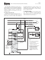
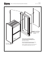
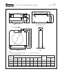
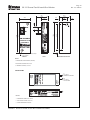
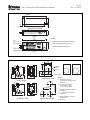
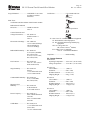
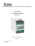
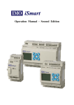
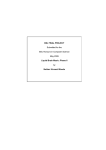
3714 Kinnear Place Saskatoon, SK Canada S7P 0A6 Ph: (306) 373-5505 Fx: (306) 374-2245 www.littelfuse.com/relayscontrols SE-135 MANUAL GROUND-FAULT GROUND-CHECK MONITOR REVISION 3-C-100314 LITTELFUSE STARTCO GROUND-FAULT GROUND-CHECK MONITOR GROUND FAULT TRIP DIAGNOSTIC ERROR SE-135 GROUND CHECK TRIP TRIP SENSOR POWER VALID VALID OPEN 8 6 2.0 1.5 4 1.0 3 .75 .50 2 10 2.5 CS10 CS40 OPEN 12 3.0 20 5.0 7.5 30 SHORT 10.0 40 12.5 50 GF TRIP LEVEL (A) .50 .70 1.0 .40 .30 .20 .10 1.3 1.6 2.0 2.5 GF TRIP TIME (s) RESET GC TEST FUSE F1: 1.5 A 500 VAC TIME DELAY Copyright 2014 by Littelfuse Startco. All rights reserved. Document Number: PM-1315-EN Printed in Canada. SE-135 Ground-Fault Ground-Check Monitor This page intentionally left blank Page i Rev. 3-C-100314 Page ii Rev. 3-C-100314 SE-135 Ground-Fault Ground-Check Monitor TABLE OF CONTENTS SECTION 1 2 LIST OF FIGURES PAGE General ................................................................. 1 Operation ............................................................. 1 2.1 Ground-Fault Circuit ............................................. 1 2.1.1 GF Trip Time Setting................................. 1 2.1.2 GF Trip Level Setting ................................ 1 2.2 Ground-Check Circuit ........................................... 1 2.3 Reset ................................................................... 2 2.4 Trip Relay ............................................................. 2 2.5 Network Communications .................................... 2 3 Indication ............................................................. 3 3.1 Ground Fault ......................................................... 3 3.2 Power .................................................................... 3 3.3 Diagnostic Error .................................................... 3 3.4 Ground Check ....................................................... 3 4 Installation ........................................................... 3 4.1 General .................................................................. 3 4.2 Monitor ................................................................. 3 4.3 Current Sensors ..................................................... 3 4.4 Termination Assembly .......................................... 3 4.5 Remote Operation ................................................. 3 4.6 Parallel-Path Isolation ........................................... 4 4.7 Ferrite Placement .................................................. 4 5 Technical Specifications ................................... 15 5.1 SE-135 ................................................................ 15 5.2 Current Sensors ................................................... 16 5.3 Termination Assemblies ..................................... 17 6 Ordering Information ....................................... 18 7 Warranty ........................................................... 18 8 Test Procedures ................................................. 19 8.1 Ground-Check Trip Tests ................................... 19 8.1.1 Latching Ground-Check Trip Test........... 19 8.1.2 Non-Latching Ground-Check Trip Test .. 19 8.2 Trip Relay Fail-Safe Mode Test.......................... 19 8.3 Current-Sensor-Verification Test ........................ 19 8.4 SE-TA12A-Series Termination Assembly Tests .................................................................... 19 8.5 Ground-Fault Performance Test.......................... 20 Appendix A SE-135 Revision History......................... 22 FIGURE 1 2 3 4 5 6 7 8 9 10 11 12 13 14 15 PAGE SE-135 Typical Application ..................................4 SE-135 Outline and Panel-Mounting Details ........5 SE-134-SMA Surface Mount Adapter and SE-135 Surface-Mounting Details .........................6 SE-IP65CVR-G Weatherproof Cover Outline ......7 SE-IP65CVR-G Weatherproof Cover Installation 8 SE-CS10 and SE-CS40 Current Sensors ...............9 SE-TA12A and SE-TA12A-WL Termination Assemblies ...........................................................10 SE-TA12ASF-WL Small-Format-Wire-Lead Termination Assembly .........................................11 RK-132 Remote Indication and Reset Kit ...........11 PPI-600V Parallel-Path Isolator ..........................12 PPI-600V Typical Installation .............................13 SE-135 with Ferrites Installed .............................14 Current Sensor Shield Connection.......................14 Ground-Fault-Test Circuit ...................................21 Termination-Assembly-Test Circuits...................21 LIST OF TABLES TABLE 1 2 3 PAGE Coil Address ..........................................................2 Holding Register Address ......................................2 Ground-Fault-Test Record ...................................20 DISCLAIMER Specifications are subject to change without notice. Littelfuse Startco is not liable for contingent or consequential damages, or for expenses sustained as a result of incorrect application, incorrect adjustment, or a malfunction. SE-135 Ground-Fault Ground-Check Monitor This page intentionally left blank. Page iii Rev. 3-C-100314 SE-135 Ground-Fault Ground-Check Monitor 1. GENERAL The SE-135 is a microprocessor-based, combination ground-fault and ground-wire monitor for resistancegrounded systems. It has a switching power supply that accepts a wide range of ac and dc voltages, and its specifications apply over an industrial temperature range at high humidity. The SE-135 meets the IEEE surgewithstand-capability tests (oscillatory and fast transient) for protective relays and relay systems. Isolated, normally open and normally closed contacts are provided for contactor control or for shunt or undervoltage operation in a breaker-trip circuit. All operating conditions are clearly annunciated and two Form C contacts are provided for remote indication. The SE-135 is housed in an anodized extruded-aluminum enclosure, and all connections are made with plug-in, wire-clamping terminal blocks. Provision is made for both panel and surface mounting. The ground-fault circuit detects fundamentalfrequency, zero-sequence current with a window-type current sensor and it verifies that the current sensor is connected and not shorted. A definite-time characteristic with 11 trip levels and 11 trip times allows coordination in virtually any resistance-grounded system. Although other current sensors may satisfy the verification circuit, only SE-CS10-series and SE-CS40-series sensors have characteristics that meet system specifications. Currentsensor verification can be disabled for a ground-checkonly application. The ground-check circuit has an open-circuit voltage of 30 Vdc, which is not a hazard to personnel, and it has an output drive current above 100 mA for optimum performance in slip-ring, commutated-load, and highinduced-ac applications. Features include an externally accessible ground-check fuse, a resistance-insertion test, 3-kV isolation between the ground-check loop and the monitor electronics, and a PPI-600V accessory for parallel-ground-path rejection. A PPI-600V will also eliminate intermachine arcing and prevent stray ac and dc currents from flowing in the monitored ground wire. Unlike ground-check circuits using other termination devices, and especially those with phase-reversal switches, a ground-check circuit using a termination device with a Zener characteristic is capable of loop measurements that are independent of current in the phase conductors. The SE-135 ground-check circuit recognizes the SE-TA12A-series 12-volt Zener characteristic as a valid end-of-line completion. This is the only passive characteristic that will satisfy the ground-check circuit’s multi-level drive, allow induced currents to circulate in the ground-check loop, survive a phase-to-ground-check fault, and clamp the ground-check voltage during the fault. Although a standard 12-volt Zener diode may engage the SE-135’s ground-check circuit, only an Page 1 Rev. 3-C-100314 SE-TA12A-series termination assembly has the compensation required to meet system specifications. 2. OPERATION 2.1 GROUND-FAULT CIRCUIT 2.1.1 GF TRIP TIME SETTING The ground-fault circuit has a definite-time characteristic with 11 settings from 0.1 to 2.5 seconds. Time-coordinated ground-fault protection requires the trip time to be longer than the trip time of downstream ground-fault devices. 2.1.2 GF TRIP LEVEL SETTING The trip level of the ground-fault circuit is switch selectable with 11 settings from 0.5 to 12.5 A for the SE-CS10-series CT and from 2 to 50 A for the SE-CS40series CT. A minimum tripping ratio of five is recommended to achieve at least 80% winding protection, and this requires the trip level to be no more than 20% of the grounding-resistor let-through current. A groundfault trip is latched, requiring a reset. A current-sensor failure will also cause a ground-fault trip. See Section 3.1. If the SE-135 is operated in a ground-check-only application and an SE-CS10 is not connected, connect terminals 17 and 18 to disable sensor verification. See Fig. 1. 2.2 GROUND-CHECK CIRCUIT The ground-check loop consists of the outgoing ground-check conductor, quick-coupler connections, the SE-TA12A-series termination assembly, the SE-TA12A connection to equipment frame or ground bus, the ground-return path, and the SE-135 cable-groundterminal connection to substation ground. The SE-135 detects a valid ground-check loop when an SE-TA12A-series termination assembly is detected in the loop and loop resistance is less than 28 ohms (45 ohms for XGC option). The loop is not valid if open (or high resistance), or if the ground-check conductor is shorted to ground. When the ground-check loop is valid, the SE-135 ground-check circuit can be tested by pressing the GC TEST button or by shorting GC TEST terminals 11 and 12. This test invalidates the loop by inserting 47 ohms (75 ohms for XGC option) in the ground-check loop and a trip should occur in less than 250 ms. The ground-check circuit is usually operated in the non-latching mode; however, it can be operated in the latching mode by connecting terminals 14 and 15. The ground-check circuit is protected by a 1.5-A timedelay fuse (F1). If the SE-135 is used in a ground-fault-only application, an SE-TA12A must be connected to the Page 2 Rev. 3-C-100314 SE-135 Ground-Fault Ground-Check Monitor ground-check and cable-ground terminals to validate the ground-check circuit. See Fig. 1. The typical maximum distance of a trailing cable is 5.0 km (3.1 miles) for the standard model and up to 10 km (6.3 miles) for the XGC option. Several factors may limit the maximum distance of the cable, including the ground-check wire gauge, and induced ac current in the ground-check loop. 2.3 RESET All ground-fault trips are latching and ground-check trips can be latching or non-latching. To reset groundfault trips or latching ground-check trips, press the RESET button or connect the RESET terminals 9 and 10. See Fig. 1. Cycling the supply voltage will also reset ground-fault trips; however, if the ground-check circuit is configured for latching fail-safe operation, the ground-check circuit will trip when supply voltage is applied. The single-shot reset circuit responds only to a momentary closure; a jammed or shorted button will not maintain a reset signal. The front-panel RESET button is inoperative when remote-reset terminals 9 and 10 are connected. See Section 4.5. 2.4 TRIP RELAY Isolated, normally open (Trip A, terminals 24 and 25) and normally closed (Trip B, terminals 22 and 23) contacts are provided for use in a contactor- or breakercontrol circuit. With no connection between terminals 12 and 13, the SE-135 trip relay operates in the fail-safe mode. This mode is used with undervoltage devices where the trip relay energizes and its normally open contact closes if the ground-fault and ground-check circuits are not tripped. This mode is recommended because: Undervoltage devices release if supply voltage fails. Undervoltage ground-check circuits do not allow the power circuit and open cable couplers to be energized until the ground-check loop is verified. The fail-safe mode of operation of the SE-135 trip relay can be used for shunt-trip circuits with a storedenergy trip source. In this case, the normally closed trip contact is used—the contact opens when the SE-135 is energized and the ground-fault and ground-check circuits are not tripped. Care must be taken to ensure safe and correct operation during power up and power down. Connect terminals 12 and 13 for non-fail-safe trip relay operation with shunt-trip devices. In this mode, the normally open trip contact is used—the trip contact is closed when a ground-fault or ground-check trip occurs. Shunt-trip circuits are not fail-safe and are not recommended because: Shunt-trip devices do not operate if supply voltage fails. Shunt-trip ground-check circuits allow the power circuit and open cable couplers to be energized for a short interval after supply voltage is applied. CAUTION: The SE-135 is not a lock-out device. Follow lock-out procedures for maintenance. 2.5 NETWORK COMMUNICATIONS An IEEE 802.3 port with Modbus® TCP Ethernet protocol is available. The SE-135 default IP address is 10.0.0.1. Use SE-MON-GFGC to change the IP address, monitor connected SE-135 units, and to issue remote commands. SE-MON-GFGC can be downloaded from www.littelfuse.com/relayscontrols. If the computer running SE-MON-GFGC has more than one active network connection, SE-MON-GFGC may not detect the SE-135. Ensure SE-MON-GFGC is not blocked by Windows Firewall by adding it to the Firewall Exceptions list in the Windows Control Panel. On start-up SE-MON-GFGC scans the network for SE-135 units and displays them in a list. Select one from the list and click “Edit” to change the IP address, subnet mask, or description. When selecting an IP address, ensure it is not already in use. Click “Apply” to save the changes. SE-MON-GFGC will pause for five seconds and scan the network again. To view the status of an SE-135, select the unit and click “Monitor”. If a warning appears, the SE-135 may have been set to an IP address that is not accessible by the network. Table 1 shows the SE-135 coil addresses. Table 2 provides the holding registers in 16-bit format. A remote reset can be generated by writing DO1 high for one second and then writing it back to low. COIL ADDRESS 00001 00002 00003 00018 TABLE 1. COIL ADDRESS DESCRIPTION NAME ATTRIBUTE GC Status GF Status Trip Relay Remote Reset Read Read Read Read/Write TABLE 2. REGISTER ADDRESS 40301 40303 DI0 DI1 DI2 DO1 HOLDING REGISTER ADDRESS DESCRIPTION ATTRIBUTE DI0 – DI11 DO0 – DO5 Read Read/Write SE-135 Ground-Fault Ground-Check Monitor 3. INDICATION 3.1 GROUND FAULT A red TRIP LED indicates a ground-fault trip and the remote-indication relay GF is energized when the groundfault circuit is not tripped (fail-safe indication-contact operation). A green SENSOR LED indicates a current sensor is correctly connected. If the SE-CS10- or SE-CS40-series current sensor is disconnected or shorted, the green LED will go out and the ground-fault circuit will trip. If the sensor fault is intermittent, the groundfault circuit will trip and the green LED will flash to indicate that the trip was initiated by a sensor fault. NOTE: The SE-CS10- and SE-CS40-series current sensors are 600-V-rated current transformers. When system voltage is above 600 V, ensure conductors passed through the sensor window are insulated to system voltage. 3.2 POWER The green POWER LED indicates that the internal power supply is on. 3.3 DIAGNOSTIC ERROR The red DIAGNOSTIC ERROR LED indicates that an internal error caused the SE-135 to trip. Return the SE-135 to the factory if a reset does not clear the trip. Induced ac current in the ground-check loop can cause the LED to flicker. This is a normal condition and does not indicate a diagnostic error; the ground-check monitoring circuit is not affected. 3.4 GROUND CHECK A red TRIP LED indicates a ground-check trip. A green VALID LED indicates a valid ground-check loop and the remote-indication relay GC is energized when the ground-check loop is valid (fail-safe indication-contact operation). Two yellow LED’s indicate the status of an invalid ground-check loop. OPEN indicates the loop resistance exceeds the trip resistance and SHORT indicates the ground-check conductor is shorted to the ground conductor. A flashing yellow LED indicates the corrected cause of a latched ground-check trip. 4. INSTALLATION 4.1 GENERAL This ground-fault ground-check monitoring system consists of an SE-135 Monitor, an SE-CS10- or SE-CS40-series Current Sensor, and an SE-TA12A-series Termination Assembly connected as shown in Fig. 1. If required, remote indication and reset can be implemented with standard pilot devices, or with an RK-132 RemoteIndication-and-Reset Kit. Page 3 Rev. 3-C-100314 4.2 MONITOR Each SE-135 is packaged with both panel- and surfacemounting hardware. Outline and panel-cutout dimensions for the SE-135 are shown in Fig. 2. To panel mount the SE-135, insert it through the panel cutout and secure it with the four supplied 8-32 locknuts and flat washers. If an optional SE-IP65CVR-G is used, follow the included installation instructions. See Figs. 4 and 5. All connections to the SE-135 are made through plugin, wire-clamping terminal blocks for 24 to 12 AWG (0.2 to 2.5 mm2) conductors. Each plug-in terminal block can be secured to the monitor by two captive screws for reliable connections in high-vibration applications. Outline dimensions and mounting details for surface mounting an SE-135 are shown in Fig. 3. Fasten the SE-134-SMA Surface-Mount Adapter to the mounting surface and make connections to the adapter terminal blocks. Follow the instructions in Fig. 3 to install or remove the SE-135. Use terminal 1 (L1) as the line terminal on ac systems or the positive terminal on dc systems. Use terminal 2 (L2/N) as the neutral terminal on ac systems or the negative terminal on dc systems. NOTE: On revision 4 and newer units, terminal 3 (SPG) is internally connected to terminal 4. For these units an external terminal-3-to-terminal-4 connection is not required, nor is it necessary to remove the terminal-3 connection for dielectric-strength testing. 4.3 CURRENT SENSORS Outline dimensions and mounting details for the SE-CS10- and SE-CS40-series current sensors are shown in Fig. 6. Pass only phase conductors through the sensor window as shown in Fig. 1. If a shield, ground, or ground-check conductor enters the sensor window, it must be returned through the window before it is terminated. Connect the current sensor to terminals 16 and 17. Ground terminal 17. Current-sensor primary and secondary connections are not polarity sensitive. See Section 4.7. 4.4 TERMINATION ASSEMBLY Outline dimensions and mounting details for the SETA12A, SE-TA12A-WL, and SE-TA12ASF-WL are shown in Figs. 7 and 8. Install the SE-TA12A at the load to complete the ground-check loop as shown in Fig. 1. Connect terminal G of the SE-TA12A to the equipment frame so that the ground-conductor-to-equipment-frame connection will be included in the monitored loop. 4.5 REMOTE OPERATION Remote indication contacts and a reset input are provided as shown in Fig. 1. Page 4 Rev. 3-C-100314 SE-135 Ground-Fault Ground-Check Monitor The optional RK-132 Remote Kit is shown in Fig. 9. Connect terminals of the green ground-check indicator to SE-135 terminals 26 and 27 and the red ground-fault indicator to terminals 19 and 21. For remote reset, connect the normally open push-button switch across terminals 9 and 10. the monitored ground wire. See Figs. 10 and 11. See Technical Note GC-10 “Parallel Path Isolator” at www.littelfuse.com/relayscontrols, or contact Littelfuse Startco for application details. 4.7 FERRITE PLACEMENT A ferrite kit is included with CE-compliant options only. Where CE compliance is desired, install each ferrite as shown in Fig. 12. If a current sensor is used, connect the shield wire as shown in Fig. 13. 4.6 PARALLEL-PATH ISOLATION A PPI-600V can be used for parallel-path rejection. A PPI-600V will also eliminate inter-machine arcing and prevent stray ac and dc currents from flowing in SE-CS10 or SE-CS40 LOAD GROUND GROUND CHECK L GC N G S E - TA 1 2 A GROUND-CHECK TERMINATION 1 L2/N L1 2 24 TRIP A 25 22 TRIP B 23 19 GF 20 GF 21 GC 27 GC 28 UV STOP START GC NOTE 3 HOLD-IN CONTACT R G S E - TA 1 2 A GF INDICATOR 26 NOTE 3 G GC INDICATOR REMOTE RESET 9 10 RESET CURRENT SENSOR NOTES: 16 17 CONNECT 17 & 18 TO DISABLE SENSOR VERIFICATION REMOTE GC TEST 11 12 CONNECT 12 & 13 FOR NON-FAIL SAFE OPERATION OF THE TRIP RELAY CONNECT 14 & 15 FOR LATCHING GROUND CHECK 13 14 15 3 4 GC TEST DISABLE 18 SENSOR VERIFICATION SE-135 SPG 5 6 7 CABLE GROUND FIGURE 1. SE-135 Typical Application. 8 1. RELAY CONTACTS SHOWN WITH SE-135 DE-ENERGIZED. 2. TERMINALS 3/4, 5/6 AND 7/8 ARE INTERNALLY CONNECTED. 3. EXTERNAL LIGHTS AND SWITCHES NOT INCLUDED WITH SE-135. OPTIONAL RK-132 REMOTE INDICATION AND RESET KIT AVAILABLE. SEE FIG. 9 AND ORDERING INFORMATION FOR DETAILS. NFS GROUNDCHECK LATCH GROUND CHECK ALTERNATE TERMINATION CIRCUIT FOR REMOTE CONTACTOR CONTROL NOTE 2 Page 5 Rev. 3-C-100314 SE-135 Ground-Fault Ground-Check Monitor 145.0 (5.71) 16.0 (0.63) 98.3 (3.87) 91.7 (3.61) PANEL THICKNESS 1.6 (0.06) TO 4.8 (0.19) LITTELFUSE STARTCO GROUND-FAULT GROUND-CHECK MONITOR GROUND FAULT TRIP DIAGNOSTIC ERROR SENSOR POWER SE-135 GROUND CHECK RESET TRIP 1 2 3 4 TRIP VALID - L1 - L2 - SPG - GC TEST NFS GC LATCH VALID OPEN 10 8 2.5 12 3.0 20 6 2.0 1.5 5.0 4 1.0 7.5 30 10.0 40 12.5 50 .40 .30 .20 .10 185.4 (7.30) CS10 CS40 GF TRIP LEVEL (A) .50 .70 1.0 (8.37) .75 .50 2 OPEN SHORT 212.6 3 CURRENT SENSOR DISABLE SENSOR VE R I FI CAT I O N 9 10 11 12 13 14 15 16 17 18 1.3 1.6 2.0 2.5 5 6 GROUND CHECK GF TRIP B GF TRIP TIME (s) TRIP A RESET 7 8 GC TEST GC CABLE GROUND 19 20 21 22 23 24 25 26 27 28 FUSE F1: 1.5 A 500 VAC TIME DELAY F1 FRONT VIEW CLEARANCE REQUIRED FOR FUSE ACCESS 35.0 (1.38) FUSE F1: 1.5 A 500 VAC TIME DELAY F1 REAR VIEW SIDE VIEW 92.7 (3.65) 76.2 (3.00) NOTES: 186.0 (7.32) 200.0 (7.87) 1. DIMENSIONS IN MILLIMETRES (INCHES). 8.2 (0.32) 25.4 25.4 (1.00) (1.00) 76.2 (3.00) 7.0 (0.28) R=4.8 (0.19) MAXIMUM 4.4 (0.173) DIA 4 LOCATIONS PANEL-MOUNT CUTOUT FIGURE 2. SE-135 Outline and Panel-Mounting Details. Page 6 Rev. 3-C-100314 8.0 (0.31) RETAINER SCREW RETAINER 6.4 114.3 (4.50) 98.3 (3.87) (0.25) SE-135 Ground-Fault Ground-Check Monitor 152.0 (5.98) LITTELFUSE STARTCO GROUND-FAULT GROUND-CHECK MONITOR GROUND FAULT DIAGNOSTIC ERROR TRIP L1 - 1 L2-2 SPG -3 -4 GROUND CHECK TRIP SENSOR POWER VALID VALID 16 CURRENT SENSOR 17 DISABLE SENSOR 18 VERIFICATION OPEN CS10 CS40 OPEN 12 3.0 20 5.0 7.5 30 SHORT 10.0 40 12.5 50 GF TRIP LEVEL (A) .50 .70 1.0 GF .40 .30 .20 .10 GROUND 5 CHECK 6 TRIP B 225.4 (8.87) 10 2.5 (8.37) 8 2.0 1.5 4 1.0 6 .75 3 .50 2 19 20 21 22 23 24 25 26 27 28 1 2 3 4 TRIP 212.6 9 RESET 10 11 GC TEST 12 (NOT USED NFS O N SE-134) 13 14 GC LATCH 15 SE-135 1.3 1.6 2.0 2.5 5 6 GF TRIP TIME (s) TRIP A GC CABLE 7 GROUND 8 RESET 7 8 GC TEST FUSE F1: 1.5 A 500 VAC TIME DELAY FUSE F1: 1.5 A 500 VAC TIME DELAY 28.6 CLEARANCE REQUIRED FOR FUSE ACCESS FRONT VIEW SE-134-SMA (1.13) F1 (1.00) (2.50) 5.0 63.5 (0.20) FRONT VIEW 25.4 SIDE VIEW NOTES: 1. DIMENSIONS IN MILLIMETRES (INCHES). (NOTE 2) 2. MOUNTING SCREWS: M4 OR 8-32 PANHEAD. INSTALLATION 215.9 (8.50) 1. LOOSEN RETAINER SCREWS, MOVE RETAINERS OUTWARD AND TIGHTEN RETAINER SCREWS. 2. MATE MONITOR WITH ADAPTER PLUG-IN TERMINALS LOOSEN RETAINER SCREWS TO LET RETAINERS SNAP OVER MONITOR BACKPLATE. 3. ENSURE THAT RETAINERS ARE AGAINST MONITOR BODY AND TIGHTEN RETAINER SCREWS. REMOVAL 1. LOOSEN RETAINER SCREWS, SLIDE RETAINERS AWAY FROM MONITOR BODY, AND TIGHTEN RETAINER SCREWS. BEZEL OUTLINE 2. PULL MONITOR FORWARD. ADAPTER PANEL OUTLINE MOUNTING DETAIL FIGURE 3. SE-134-SMA Surface Mount Adapter and SE-135 Surface-Mounting Details. Page 7 Rev. 3-C-100314 TO PREVENT UNAUTHORIZED ENTRY: (1.34) 34.0 SE-135 Ground-Fault Ground-Check Monitor 1. USE WIRE SEAL THROUGH HOLES IN WEATHERPROOF COVER ASSEMBLY, OR 2. SECURE WITH THE PLASTIC THREAD FORMING SCREW SUPPLIED IN KIT. SHOWN WITH SEAL (9.84) 250.0 TOP VIEW HOLE FOR SEAL WIRE 127.0 (5.00) FRONT VIEW NOTES: 1. DIMENSIONS SHOWN IN MILLIMETRES (INCHES). 2. SHOWN WITH WEATHERPROOF SNAPS CLOSED. 3. REFER TO PANEL MOUNTING CUTOUT (FIGURE 2) FOR PANEL MOUNTING DETAIL. FIGURE 4. SE-IP65CVR-G Weatherproof Cover Outline. SIDE VIEW Page 8 Rev. 3-C-100314 SE-135 Ground-Fault Ground-Check Monitor INSTALL O-RING INTO GROOVE IN THE REAR OF WEATHERPROOF WINDOW. INSERT THE SE-135 THROUGH OPENING OF THE WEATHERPROOF WINDOW, UNTIL IT IS SECURELY NESTED TO THE BACK OF THE DARK GREY PVC PANEL. FRONT-PANEL DETAILS NOT SHOWN. INSTALL O-RING INTO THE GROOVE IN THE REAR OF WEATHERPROOF WINDOW ASSEMBLY. INSERT ASSEMBLY INTO PANEL AND FASTEN WITH THE HARDWARE PROVIDED WITH THE SE-135. FIGURE 5. SE-IP65CVR-G Weatherproof Cover Installation. Page 9 Rev. 3-C-100314 SE-135 Ground-Fault Ground-Check Monitor C F C SE-CS10-6, SE-CS10-8, AND SE-CS40-6 D G D E H SE-CS10-2.5 AND SE-CS10-4 MOUNTING DETAIL TOP E TERMINAL LOCATION MAY VARY SE-CSXX-X R CURRENT SENSOR X1 6 0 0 V I NS . C L A S S 1 0 K V B IL COUNTRY OF ORIGIN: USA B J A H1 C 1-800-TEC-FUSE (1-800-832-3873) I FRONT SIDE NOTES: 1. DIMENSIONS IN MILLIMETRES (INCHES). 2. RoHS COMPLIANCE PENDING. PART NUMBER 3. EN 60044-1 COMPLIANT. DIMENSIONS A B C D E F G MOUNTING SCREW H I J 88.9 (3.50) N/A SE-CS10-2.5 63.5 (2.50) 135.1 (5.32) 124.0 (4.88) 72.6 (2.86) 27.9 (1.10) 69.9 (2.75) 54.4 (2.14) M4 (8-32) 108.0 (4.25) 184.0 (7.24) 169.9 (6.69) 77.2 (3.04) 32.5 (1.28) 123.7 (4.87) 60.5 (2.38) M4 (8-32) SE-CS10-4 138.2 (5.44) 138.2 (5.44) SE-CS10-6 160.3 (6.31) 229.0 (9.00) 215.9 (8.50) 101.6 (4.00) 31.8 (1.25) 165.0 (6.50) 73.2 (2.88) M10 (0.375) SE-CS40-6 171.5 (6.75) 171.5 (6.75) SE-CS10-8 209.5 (8.25) 279.4 (11.00)266.7 (10.50) 108.7 (4.28) 38.9 (1.53) 225.0 (8.86) 80.0 (3.15) M10 (0.375) 200.7 (7.90) 200.7 (7.90) FIGURE 6. SE-CS10 and SE-CS40 Current Sensors. Page 10 Rev. 3-C-100314 SE-135 Ground-Fault Ground-Check Monitor SE-TA12A 41.5 40.0 (1.63) 10.5 (0.41) 10.5 (0.87) (0.41) (0.75) 8.0 22.2 (1.57) (0.31) 40.0 (1.57) 19.0 NOTE 2 GC 89.0 (3.50) (0.31) (4.13) 8.0 105.0 (4.13) 105.0 G SE-TA12A TERMINATION ASSEMBLY 4.5 (0.18) Ø, C’BORE 10.0 (0.39) Ø 3.2 (0.13) DEEP SIDE FRONT MOUNTING DETAIL NOTES: 1. DIMENSIONS IN MILLIMETRES (INCHES). 2. MOUNTING SCREWS: M4 OR 8-32. 3. TERMINAL SCREWS 6-32 x 0.25. SE-TA12A-WL SE-TA12A-WL T E R M I N AT I O N A S S E M B LY NOTES: 1. DIMENSIONS SAME AS SE-TA12A. 2. WIRE LEADS #14 AWG (2.08 mm2). 3. CAN BE IMMERSED IN GLYCOL. FIGURE 7. SE-TA12A and SE-TA12A-WL Termination Assemblies. G 356 (14) OF GREEN/YELLOW WIRE GC 356 (14) OF YELLOW WIRE Page 11 Rev. 3-C-100314 SE-135 Ground-Fault Ground-Check Monitor 12.7 (0.50) 3.2 (0.13) 50.8 (2.00) 12.7 4.0 (0.16) (0.50) NOTE 2 MOUNTING DETAIL SE-TA12ASF-WL SE-TA12 ASF-WL TERMINATION ASSY Serial No: DM131000182 Rev: Rating: 12.0 Vdc @ 105 mA 12 W Max C R US LR 53428 01 Use with: SE-135 Ground-Fault Ground-Check Monitor SIDE NOTES: 58.8 (2.32) 1. DIMENSIONS IN MILLIMETRES (INCHES). 19.0 (0.75) GC 300 (12) OF YELLOW WIRE G 300 (12) OF GREEN/YELLOW WIRE 2. MOUNTING SCREWS M3.5 OR 6-32. 3. CAN BE IMMERSED IN GLYCOL. TOP FIGURE 8. SE-TA12ASF-WL Small-Format-Wire-Lead Termination Assembly. 30.0 (1.18) GROUND CHECK 29.9 (1.17) PUSH BUTTON (1.71) 43.5 36.6 (1.44) (0.59) 22.2 (0.87) DIA NOTES: LEGEND PLATES PILOT LIGHTS 14.9 (0.59) NOTE 4 30.0 MINIMUM (1.18) 1. TWO RED LED LIGHTS 24-120 VAC/DC, NOT POLARITY SENSITIVE. 29.9 (1.17) MOUNTING DETAIL FIGURE 9. RK-132 Remote Indication and Reset Kit. 2. YELLOW PUSH BUTTON 3 A @ 240 VAC - A600, 0.5 A @ 125 VDC - Q600. (1.57) 36.6 (1.44) GROUND FAULT LEGEND PLATE 40.0 MINIMUM 17.3 (0.68) 22.5 (0.89) 15.0 X1 X2 43.5 (1.71) 25.0 (0.98) RESET 3. DIMENSIONS IN MILLIMETRES (INCHES). 4. ----- INDICATES CLEARANCE REQUIRED. 5. PANEL THICKNESS 1.0 TO 6.0 (0.04 TO 0.24). 6. NEMA 4X. Page 12 Rev. 3-C-100314 SE-135 Ground-Fault Ground-Check Monitor 8-32 TAP 34.9 (1.38) 152.4 260.4 (10.25) 190.5 (7.50) 63.5 (2.50) 12.7 19.1 (0.75) (0.50) 19.1 (0.75) 9.5 DIA. (0.38 DIA.) 34.9 (1.38) 38.1 (1.50) 26.2 (1.03) 102.4 (4.03) 38.1 (1.50) (6.00) 235.0 (9.25) NOTES: 1. FIGURE 10. PPI-600V Parallel-Path Isolator. DIMENSIONS IN MILLIMETRES (INCHES). Page 13 Rev. 3-C-100314 SE-135 Ground-Fault Ground-Check Monitor GROUND CHECK MONITOR SE-105, SE-107, SE-134C, OR SE-135 CABLE GROUND G GROUND CHECK GC GC G OUTGOING GROUND CHECK OUTGOING GROUND INCOMING GROUND CHASSIS GROUND BUS PPI-600V NOTES: 1. THE PARALLEL-PATH ISOLATOR IS NOT POLARIZED. EITHER FLANGE CAN BE CONNECTED TO CHASSIS. 2. THE OUTGOING GROUND MUST BE ISOLATED FROM THE CHASSIS GROUND BUS. IF A FLANGE-MOUNTED RECEPTACLE IS USED, VERIFY THAT THE FLANGE IS ISOLATED FROM THE GROUND PIN, AND - USE A MATING PLUG WITH A NON-METALLIC HOUSING, OR - ISOLATE THE FLANGE FROM THE CHASSIS IF THE MATING PLUG HAS A METALLIC HOUSING. 3. CABLE PLUGS AND RECEPTACLES WITH GROUNDED METAL HOUSING MUST BE ISOLATED FROM GROUND TO PREVENT PARALLEL GROUND PATHS. 4. FOR SYSTEMS ABOVE 600 VAC, CONNECT A V131DA40 MOV ACROSS THE PPI-600V. FIGURE 11. PPI-600V Typical Installation. SE-135 Ground-Fault Ground-Check Monitor Page 14 Rev. 3-C-100314 NOTES: 1. PASS WIRES FROM TERMINALS 9 TO 15 THROUGH A FERRITE. 2. PASS THE SHIELDED CABLE FROM TERMINALS 16 TO 17 THROUGH A FERRITE. CONNECT THE SHIELD TO CHASSIS AS SHOWN IN FIG. 13. NOTE 1 3. DOUBLE LOOP THE WIRES FROM TERMINALS 19 TO 28 THROUGH A FERRITE. 4. PASS WIRES FROM FERRITE (NOTE 3) THROUGH A SECOND FERRITE. NOTE 2 5. ALL FERRITES ARE LAIRD TECHNOLOGIES 28A2024-0A2 AND ARE ROHS COMPLIANT. NOTE 3 FIGURE 12. SE-135 with Ferrites Installed. FIGURE 13. Current Sensor Shield Connection. NOTE 4 SE-135 Ground-Fault Ground-Check Monitor 5. TECHNICAL SPECIFICATIONS 5.1 SE-135 Supply: Option 0 .................................25 VA, 120-240 Vac (+10, -45%), 50-400 Hz; 15 W, 110-250 Vdc (+10, -25%) Option 1 .............................. 15 W, 24-48 Vdc (+50, -25%); 20 VA, 48 Vac (+10, -55%), 50-100 Hz Ground-Fault Circuit: Digital Filter ....................... 50 to 60 Hz, Bandpass 3 dB Frequency Response .. 30 to 90 Hz Trip-Level Settings: SE-CS10-x ...........................50, .75, 1.0, 1.5, 2.0, 2.5, 3.0, 5.0, 7.5, 10.0, and 12.5 A SE-CS40-x ..........................2, 3, 4, 6, 8, 10, 12, 20, 30, 40, and 50 A Trip-Time Settings .............. .10, .20, .30, .40, .50, .70, 1.0, 1.3, 1.6, 2.0, and 2.5 s Thermal Withstand: SE-CS10-x........................ 150 A Continuous 1,000 A for 2.5 s (Ground-Fault Current) SE-CS40-x ..........................600 A Continuous 4,000 A for 2.5 s (Ground-Fault Current) Sensor Lead Resistance ...... 2 maximum Trip-Level Accuracy: SE-CS10-x ....................... 5% or 0.1 A SE-CS40-x ....................... 5% or 0.4 A Trip-Time Accuracy ........... +50, -15 ms Sensor Verification ............. Enabled or Disabled Sensor-Fault Detection ....... Open and Short Trip Mode ........................... Latching Ground-Check Circuit: Open-Circuit Voltage ......... 30 Vdc Output Impedance............... 136 Loop Current ...................... 105 mA Induced-ac Withstand ......... 60 Vac Continuous, 120 Vac for 10 s, 250 Vac for 0.25 s Pull-in Time ........................ 1.5 s Trip Resistance: Standard ........................... 28 ± 10% XGC Option ..................... 45 ± 10% Trip Time: Standard at 50 .............. 220 ± 30 ms XGC Option at 75 ........ 220 ± 30 ms Short Detection ................... Yes Isolation .............................. 3 kV, 60 Hz, 1 s Test ..................................... Front-Panel Button and Remote, N.O. Contact Fuse Rating (F1) ................. 1.5 A, 500 Vac, Time Delay Fuse Part Number ............... FNQ 1½ Buss Fusetron Page 15 Rev. 3-C-100314 Trip Mode........................... Latching or Non-Latching Trip Relay: CSA/UL Contact Rating..... 8 A Resistive 250 Vac, 5 A 30 Vdc, 0.25 HP, B300 Pilot Duty Supplemental Contact Ratings: Make/Carry (0.2 s)........... 30 A Break dc ........................... 75 W Resistive, 35 W Inductive (L/R < 0.04) Break ac ........................... 2,000 VA Resistive, 1,500 VA Inductive (PF > 0.4) Subject to maximums of 8 A and 250 V (ac or dc) Contact Configuration ........ Isolated N.O. and N.C. Contacts Operating Mode.................. Fail-Safe or Non-Fail-Safe Remote-Indication Relays: CSA/UL Contact Rating..... 8 A Resistive 250 Vac, 8 A 30 Vdc Supplemental Contact Ratings: Make/Carry (0.2 s)........... 20 A Break dc ........................... 50 W Resistive, 25 W Inductive (L/R < 0.04) Break ac ........................... 2,000 VA Resistive, 1,500 VA Inductive (PF > 0.4) Subject to maximums of 8 A and 250 V (ac or dc) Contact Configuration ........ N.O and N.C. (Form C) Operating Mode.................. Fail-Safe Trip Reset ................................. Front-Panel Button and Remote, N.O. Contact Terminal Block Rating ............. 10 A, 300 Vac, 12 AWG (2.5 mm2) PWB Conformal Coating ......... MIL-1-46058 qualified, UL QMJU2 recognized Mounting Configuration .......... Panel Mount and Surface Mount Dimensions: Height .................................... 213 mm (8.4”) Width ..................................... 99 mm (3.9”) Depth ..................................... 132 mm (5.2”) Shipping Weight ...................... 2.3 kg (5.1 lb) Environment: Operating Temperature ......... -40 to 60°C (-40 to 140°F) Storage Temperature ............. -55 to 80°C (-67 to 176°F) Humidity............................. 85% Non-Condensing Page 16 Rev. 3-C-100314 SE-135 Ground-Fault Ground-Check Monitor Surge Withstand ....................... ANSI/IEEE 37.90.1-2002 (Oscillatory and Fast Transient) EMC Tests: Verification tested in accordance with EN 60255-26:2009. Radiated and Conducted Emissions ............................ CISPR 22:2008-09 Class A Current Harmonics and Voltage Fluctuations ........... IEC 61000-3-2 and IEC 61000-3-3 Class A Electrostatic Discharge ....... IEC 61000-4-2 ± 6 kV contact discharge (direct and indirect) ± 8 kV air discharge Radiated RF Immunity ....... IEC 61000-4-3 10 V/m, 80-1,000 MHz, 80% AM (1 kHz) 10 V/m, 1.0 to 2.7 GHz, 80% AM (1 kHz) Fast Transient ..................... IEC 61000-4-4 Class A: ± 4 kV (on AC mains and I/O lines) Surge Immunity .................. IEC 61000-4-5 Zone B ± 1 kV differential mode ± 2 kV common mode Conducted RF Immunity .... IEC 61000-4-6 10 V, 0.15-80 MHz, 80% AM (1 kHz) Magnetic Field Immunity ............................ IEC 61000-4-8 50 Hz and 60 Hz 30 A/m and 300 A/m Power Frequency ................ IEC 60255-22-7 Zone A: differential mode 150 Vrms Zone A: common mode 300 Vrms 1 MHz Burst ....................... IEC 61000-4-18 ± 1 kV differential mode (line-to-line) ± 2.5 kV common mode Certification ............................. CSA Canada and USA R C LR 53428 US UL Listed Australia N11659 CE, European Union FCC To: CSA C22.2 No. 14 Industrial Control Equipment UL 508 Industrial Control Equipment UL 1053 Ground Fault Sensing and Relaying Equipment CE Low Voltage Directive IEC 61010-1:2010 (3rd Edition) FCC CFR47, Part 15, Subpart B, Class A – Unintentional Radiators Compliance .............................. RoHS Pending 5.2 CURRENT SENSORS Environment: Operating Temperature....... -40 to 60C (-40 to 140°F) Storage Temperature .......... -55 to 80C (-67 to 160°F) SE-CS10-2.5: Current Ratio ...................... 1,000:5 A Insulation ............................ 600-V Class Window Diameter .............. 63 mm (2.5”) Shipping Weight................. 690 g (1.5 lb) SE-CS10-4: Current Ratio ...................... 1,000:5 A Insulation ............................ 600-V Class Window Diameter .............. 108 mm (4.2”) Shipping Weight................. 1.9 kg (4.3 lb) SE-CS10-6: Current Ratio ...................... 1,000:5 A Insulation ............................ 600-V Class Window Diameter .............. 160 mm (6.3”) Shipping Weight................. 2.2 kg (4.8 lb) Page 17 Rev. 3-C-100314 SE-135 Ground-Fault Ground-Check Monitor SE-CS10-8: Current Ratio ...................... 1,000:5 A Insulation ............................ 600-V Class Window Diameter............... 209 mm (8.2”) Shipping Weight ................. 2.2 kg (4.8 lb) SE-CS40-6: Current Ratio ...................... 800:1 A Insulation ............................ 600-V Class Window Diameter............... 160 mm (6.3”) Shipping Weight ................. 1.8 kg (4.0 lb) Certification.............................. CE(1), European Union Compliance .............................. IEC 60044-1 RoHS Pending NOTES: (1) When connected to an SE-135. 5.3 TERMINATION ASSEMBLIES SE-TA12A: Characteristic ...................... 12-V Zener, Temperature Compensated Circuit Type ........................ High-Current Shunt Regulator Reverse Voltage.................. 12 ±0.03 Vdc @ 100 mA Forward Voltage ................. 0.5 ±0.1 Vdc @ 100 mA Operating Temperature ....... -40 to 60°C (-40 to 140°F) Current Range ..................... 2 mA to 25 A Maximum Clamping Voltage ............................... 55 V @ 250 A, 5x20 µs Pulse Power Rating ...................... 50 W Screw Terminal................... 6-32 x 0.25 Dimensions ......................... 105 x 40 x 41.5 mm (4.13 x 1.57 x 1.63”) Shipping Weight ................. 300 g (0.7 lb) SE-TA12A-WL: Characteristic ...................... 12-V Zener, Temperature Compensated Circuit Type ........................ High-Current Shunt Regulator Reverse Voltage.................. 12 ±0.03 Vdc @ 100 mA Forward Voltage ................. 0.5 ±0.1 Vdc @ 100 mA Operating Temperature ....... -40 to 60°C (-40 to 140°F) Current Range ..................... 2 mA to 25 A Maximum Clamping Voltage ............................... 55 V @ 250 A, 5x20 µs Pulse Power Rating ...................... 50 W Wire Leads ......................... 14 AWG (2.08 mm2), 356 mm (14”) Dimensions ......................... 105 x 40 x 22.2 mm (4.13 x 1.57 x 0.87”) Shipping Weight................. 300 g (0.7 lb) SE-TA12ASF-WL: Characteristic ...................... 12-V Zener, Temperature Compensated Circuit Type........................ High-Current Shunt Regulator Reverse Voltage ................. 12 ±0.03 Vdc @ 100 mA Forward Voltage................. 0.5 ±0.1 Vdc @ 100 mA Operating Temperature....... -40 to 60°C (-40 to 140°F) Current Range .................... 2 mA to 15 A Maximum Clamping Voltage ............................... 55 V @ 250 A, 5x20 µs Pulse Power Rating ...................... 12 W Wire Leads ......................... 18 AWG (0.82 mm2), 300 mm (11.8”) Dimensions ......................... 58.8 x 19 x 12.7 mm (2.32 x 0.75 x 0.5”) Shipping Weight................. 45 g (0.1 lb) Certification ............................. CSA Canada and USA R C LR 53428 US UL Listed CE(1), European Union NOTES: (1) When connected to an SE-135. SE-135 Ground-Fault Ground-Check Monitor 6. ORDERING INFORMATION(1) SE-135- (1) (2) (3) Network Communications: 0 None 3 Ethernet(2) Power Supply: 0 Universal ac/dc Supply 1 24- to 48-Vdc Supply(2)(3) Ground Check Options: Blank Standard XGC Extended-GC-Trip Resistance All options include CE/C-Tick unless otherwise stated. CE/C-Tick models include a ferrite kit. CE/C-Tick not available. Not available with Ethernet network communications option. Ground-Check Termination: SE-TA12A .......................... 50-W Termination Assembly with Screw Terminals SE-TA12A-WL .................. 50-W Termination Assembly with Wire Leads SE-TA12ASF-WL .............. 12-W Small-Format Termination Assembly with Wire Leads Current Sensors: SE-CS10-2.5 ....................... Current Sensor, 63 mm (2.5”) window SE-CS10-4 .......................... Current Sensor, 108 mm (4.2”) window SE-CS10-6 .......................... Current Sensor, 160 mm (6.3”) window SE-CS10-8 .......................... Current Sensor, 209 mm (8.2”) window SE-CS40-6 .......................... Current Sensor, 160 mm (6.3”) window Parallel Path Isolator PPI-600V ............................ For system voltages up to 600 Vac Page 18 Rev. 3-C-100314 Accessories: RK-132 ............................... Remote Indication and Reset, includes two 24120-V pilot lights, a reset push button, and legend plates SE-IP65CVR-G .................. Hinged transparent cover, IP65 SE-134-SMA ...................... Surface-Mount Adapter, included with SE-135 SE-134-HDWR .................. Hardware Kit (excludes ferrites and SE-134-SMA), included with SE-135 7. WARRANTY The SE-135 Ground-Fault Ground-Check Monitor is warranted to be free from defects in material and workmanship for a period of five years from the date of purchase. Littelfuse Startco will (at Littelfuse Startco’s option) repair, replace, or refund the original purchase price of an SE-135 that is determined by Littelfuse Startco to be defective if it is returned to the factory, freight prepaid, within the warranty period. This warranty does not apply to repairs required as a result of misuse, negligence, an accident, improper installation, tampering, or insufficient care. Littelfuse Startco does not warrant products repaired or modified by non-Littelfuse Startco personnel. SE-135 Ground-Fault Ground-Check Monitor 8. TEST PROCEDURES 8.1 GROUND-CHECK TRIP TESTS 8.1.1 LATCHING GROUND-CHECK TRIP TEST Connect the monitor, current sensor and termination assembly as shown in Fig 14. Connect terminals 14 and 15 for latching operation. With supply voltage applied, the POWER, SENSOR, and VALID LED’s will be on. Open the ground-check loop by removing either the GC or G connection between the monitor and the termination assembly (pressing the faceplate GC TEST button will also perform an open-ground-check test). The monitor will trip. The trip contacts (terminals 22-23 and 24-25) and the ground-check indication contacts (terminals 26-27 and 26-28) will change state. The VALID LED will be off, and both the GROUND CHECK TRIP and the OPEN LED’s will be on. Reconnect the ground-check loop. The VALID and TRIP LED’s will be on and the OPEN LED will be flashing. The TRIP contacts (terminals 22-23 and 24-25) will remain latched and ground-check indication contacts (terminals 26-27 and 26-28) will change state. Reset the monitor. Short the ground-check loop by connecting G to GC. The monitor will trip. The trip contacts (terminals 22-23 and 24-25) and the ground-check indication contacts (terminals 26-27 and 26-28) will change state. The VALID LED will be off, and both the GROUND CHECK TRIP and the SHORT LED’s will be on. Remove the short from G to GC. The VALID and TRIP LED’s will be on and the SHORT LED will be flashing. The TRIP contacts (terminals 22-23 and 24-25) will remain latched and ground-check indication contacts (terminals 26-27 and 26-28) will change state. Reset the monitor. 8.1.2 NON-LATCHING GROUND-CHECK TRIP TEST Connect the monitor, current sensor and termination device as shown in Fig. 14. With supply voltage applied, the POWER, SENSOR, and VALID LED’s will be on. Open the ground-check loop by removing either the GC or G connection between the monitor and the termination assembly (pressing the faceplate GC Test button will also perform an open circuit test). The monitor will trip. The trip contacts (terminals 22-23 and 24-25) and the ground-check indication contacts (terminals 26-27 and 26-28) will change state. The VALID LED will be off, and both the GROUND CHECK TRIP and the OPEN LED’s will be on. Reconnect the ground-check loop. The monitor will reset. Page 19 Rev. 3-C-100314 Short the ground-check loop by connecting G to GC. The monitor will trip. The trip contacts (terminals 22-23 and 24-25) and the ground-check indication contacts (terminals 26-27 and 26-28) will change state. The VALID LED will be off, and both the GROUND CHECK TRIP and the SHORT LED’s will be on. Remove the short from G to GC. The monitor will reset. 8.2 TRIP RELAY FAIL-SAFE MODE TEST Connect the monitor, current sensor and termination device as shown in Fig. 14. With supply voltage applied, the POWER, SENSOR, and VALID LED’s will be on. The output contacts between terminals 22 and 23 will be open and between 24 and 25 will be closed. Remove the supply voltage. The output contacts between terminals 22 and 23 will close and the output contacts between terminals 24 and 25 will open. 8.3 CURRENT-SENSOR-VERIFICATION TEST Connect the monitor, current sensor and termination device as shown in Fig. 14. With supply voltage applied, the POWER, SENSOR, and VALID LED’s will be on. Open the current-sensor circuit by disconnecting one of the sensor leads. The monitor will trip. The trip contacts (terminals 22-23 and 24-25) and the ground-fault indication contacts (terminals 19-20 and 19-21) will change state. The GROUND FAULT TRIP LED will be on and the SENSOR LED will be off. Reconnect the current sensor. The GROUND FAULT TRIP LED will stay on and the SENSOR LED will flash. The output contacts will remain latched. Reset the monitor. Short the current sensor by connecting terminals 16 and 17. The monitor will trip. The trip contacts (terminals 22-23 and 24-25) and the ground-fault indication contacts (terminals 19-20 and 19-21) will change state. The GROUND FAULT TRIP LED will be on and the SENSOR LED will be off. Remove the short from terminals 16 and 17. The GROUND FAULT TRIP LED will stay on and the SENSOR LED will flash. The output contacts will remain latched. Reset the monitor. 8.4 SE-TA12A-SERIES TERMINATION ASSEMBLY TESTS Apply 24 Vdc across the series combination of a 100-, 5-W current-limiting resistor and the termination assembly, as shown in Fig. 15. In the reverse biased test, the voltage should be 12 V across the termination assembly terminals. In the forward biased test, the voltage across the termination assembly terminals should be between 0.3 and 0.9 V. Page 20 Rev. 3-C-100314 SE-135 Ground-Fault Ground-Check Monitor 8.5 GROUND-FAULT PERFORMANCE TEST To meet the requirements of the National Electrical Code (NEC), as applicable, the overall ground-fault protection system requires a performance test when first installed. A written record of the performance test is to be retained by those in charge of the electrical installation in order to make it available to the authority having jurisdiction. A test-record form is provided for recording the date and the final results of the performance tests. The following ground-fault system tests are to be conducted by qualified personnel: a) Evaluate the interconnected system in accordance with the overall equipment manufacturer’s detailed instructions. b) Verify proper location of the ground-fault current sensor. Ensure the cables pass through the groundfault-current-sensor window. This check can be done visually with knowledge of the circuit. The connection of the current-sensor secondary to the SE135 is not polarity sensitive. c) Verify that the system is correctly grounded and that alternate ground paths do not exist that bypass the current sensor. High-voltage testers and resistance bridges can be used to determine the existence of alternate ground paths. d) Verify proper reaction of the circuit-interrupting device in response to a simulated or controlled ground-fault current. To simulate ground-fault current, use CT-primary current injection. Fig. 14 shows a test circuit using Littelfuse Startco GroundFault-Relay Test Units. The SE-400 has a programmable output of 0.5 to 9.9 A for a duration of 0.1 to 9.9 seconds. Set the test current to 120% of GF TRIP LEVEL. The SE-100T provides a test current of 0.65 or 2.75 A for testing 0.5- and 2.0-A trip levels. Inject the test current through the current-sensor window for at least 2.5 seconds. Verify that the circuit under test has reacted properly. Correct any problems and re-test until the proper reaction is verified. e) Record the date and the results of the test on the attached test-record form. TABLE 3. GROUND-FAULT-TEST RECORD DATE TEST RESULTS Retain this record for the authority having jurisdiction. Page 21 Rev. 3-C-100314 SE-135 Ground-Fault Ground-Check Monitor NOTES: 1. MOMENTARILY CONNECT 9 & 10 TO PERFORM REMOTE RESET. 2. MOMENTARILY CONNECT 11 & 12 TO PERFORM REMOTE GROUND-CHECK TEST. 3. CONNECT 12 & 13 FOR NON-FAIL SAFE OPERATION OF THE TRIP RELAY. NOTE 6 24 TRIP A 25 22 TRIP B 23 19 GF 20 GF 21 26 GC 27 GC 28 4. CONNECT 14 & 15 FOR LATCHING GROUND-CHECK TRIP. OHMS 5. CONNECT 17 & 18 TO DISABLE CURRENTSENSOR VERIFICATION. 6. CONTACTS SHOWN DE-ENERGIZED. SUPPLY VOLTAGE L 1 N 2 L1 SE-CS10 CURRENT SENSOR 16 L2/N CURRENT SENSOR RESET DISABLE 18 SENSOR VERIFICATION 17 9 NOTE 1 10 11 NOTE 2 12 NOTE 5 SUPPLY VOLTAGE GC TEST L N OUTPUT NOTE 3 13 14 NOTE 4 15 3 4 NFS GROUND-FAULT RELAY TEST UNIT GROUNDCHECK LATCH GROUND CHECK SPG 5 6 (SE-100T or SE-400) GC G 7 CABLE GROUND 8 SE-TA12A-SERIES TERMINATION ASSEMBLY SE-135 FIGURE 14. Ground-Fault-Test Circuit. 100 Ω 5 W 100 Ω 5 W + 24 Vdc - 24 Vdc - + GC GC G G SE-TA12A-SERIES TERMINATION ASSEMBLY SE-TA12A-SERIES TERMINATION ASSEMBLY VOLTS REVERSE-BIASED TEST FIGURE 15. Termination-Assembly-Test Circuits. VOLTS FORWARD-BIASED TEST Page 22 Rev. 3-C-100314 SE-135 Ground-Fault Ground-Check Monitor MANUAL RELEASE DATE APPENDIX A SE-135 REVISION HISTORY MANUAL PRODUCT REVISION REVISION (REVISION NUMBER ON PRODUCT LABEL) October 3, 2014 3-C-100314 November 12, 2013 3-B-111213 May 14, 2013 3-A-050613 04D MANUAL REVISION HISTORY REVISION 3-C-100314 SECTION 4 Figs. 7, 8, and 11 updated. APPENDIX A Revision history updated. REVISION 3-B-111213 SECTION 2 Maximum trailing cable length added. SECTION 5 Additional termination assembly and compliance specifications added. APPENDIX A Revision history updated. REVISION 3-A-050613 SECTION 2 Network communications added. SECTION 4 Ferrite placement instructions added. SECTION 5 CE specifications, XGC option, SE-CS40-6 specifications and dimensions added. SECTION 6 Ordering information updated. APPENDIX A Revision history added. PRODUCT REVISION HISTORY REVISION 04D Ferrite kit added.