1
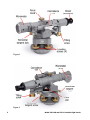
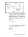
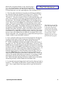
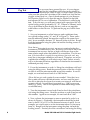
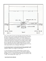
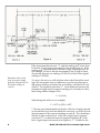
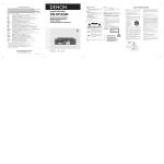
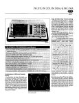
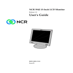
Model 545-190 and 545-1
Precision Sight Levels
Operating
Procedures Manual
Instrument
Company
Helping the World Measure
Since 1927
www.brunson.us
Brunson Instrument Company
8000 E. 23rd Street
Kansas City, MO 64129
Tel: 816.483.3187
Toll free: 877-632-7873
Fax: 816.241.1945
Copyright 2008 Brunson Instrument Company
Copyright 2008-2011 Brunson Instrument Company
All rights reserved.
Table of Contents 1 Rough Leveling 3 Measuring 5 Plate Vial Adjustment 6 Peg Test 10 How to Reduce Error Thank you for purchasing a Brunson Precision Sight Level. Remember that our customer support does not stop after shipment of a product—we are here to help you with any measurement challenges that you may have. Model 545‐190, 545‐1 Precision Sight Levels This manual applies to the Brunson Instrument Company Model 545‐190 and 545‐1 Precision Sight Levels. Mount the instrument firmly on any stand having a Rough Leveling 3½” x 8 external thread. Loosen the horizontal tan‐
gent lock and turn the telescope so that its axis is lo‐
cated directly over one opposing pair of the leveling screws. View the plate vial directly from above and bring its bubble to the center by using the instrument leveling screws. (Refer to Figures 1 and 2.) We will call the current telescope orientation “Position 1”. Position yourself so that you are facing the plate vial side of the instrument and looking perpendicularly at the side of the tele‐
scope. Put a thumb and forefinger on the leveling screws which are on the left and right sides of the base and under the telescope. Then to move the bubble, turn the leveling screws at the same time, and in opposite directions (thumbs moving together or thumbs moving apart). The bubble will move in the direction of movement of your left thumb. Move the bubble so that it is in the middle of the plate vial, and at least in line with the inscribed circle (it probably won’t be exactly centered). Now move your hands to the other set of lev‐
eling screws, and, using the same process, move the bubble directly under the inscribed circle in the center of the plate vial. You may have to repeat this entire process a couple of times to get the bubble centered. Unlike our transit instru‐
ments, precisely ʺplumbingʺ the Brunson model 545 Precision Sight Level is not re‐
quired for precise vertical measurements. This is because you use the tilt‐
ing screw to precisely level the telescope prior to every scale or target read‐
ing. Now, rotate the telescope section of the instrument 180 degrees, lo‐
cating it back again over the same pair of leveling screws but point‐
ing in the opposite direction. We’ll call this “Position 2”. Check to determine whether the bubble is still in the center of the plate vial. If so, the instrument is now rough leveled. However, if the bubble does not remain centered when the instrument is rotated to Position 2, the plate vial requires calibration. See “Adjusting the Plate Vial” in this manual. After rough leveling, the instrument should be pointed at the target and focused with the focusing knob located on top of the telescope barrel. Operating Procedures Manual
1
Figure 1 Figure 2 2
Model 545-190 and 545-1 Precision Sight Levels
The coincidence level must be brought into exact co‐
Measuring incidence by tilting the telescope barrel using the tilt‐
ing screw. Turn the turret of the coincidence level so that you can see the image of the bubble. You are actually seeing a split image of both ends of the bubble, folded back on one an‐
other. They must be brought into coincidence so that it looks like one uninterrupted bubble image (See Figure 3). When this occurs, the vial is precisely level. Once you gain a little experience looking at this image and detecting a mismatch in the bubble halves, you Prior to using the tele‐
should be able to level the instrument within an arcsecond. scope, bring the reticle (crosshairs) into sharp black focus for your own eyesight by turning the ad‐
justable ocular (eyepiece) lens. Donʹt try to focus the target or ʺfieldʺ image in this manner ‐ just the reti‐
cle. Figure 3 You may now take a measurement using the micrometer. The mi‐
crometer allows you to measure exactly how far your target is lo‐
cated above or below the instrument’s line of sight, which should be dead level at this point. Let’s look at an example of taking measurements to determine if a table is level. (See Figure 4.) You put a scale oriented vertically, standing straight up from the table. It may be mounted in any manner (e.g., our magnetic scale holders) as long as the end of the scale is firmly and squarely in contact with the table top. Vertical orientation of the scale is easily established, if required, using a Brunson scale level. Now, look through the telescope at the scale and focus it precisely. The crosshairs will be located in some arbi‐
trary position along the scale. Let’s say that the crosshairs are somewhere between the scale’s 3.2 and 3.3 markers. The microme‐
ter on the front of your telescope contains a block of glass that when rotated, moves the incoming image up and down by known amounts. Turn the graduated drum on the micrometer, which off‐
sets the image, (making it appear to move up and down) until the crosshairs appear to be right in line with the 3.2 mark on the scale. Look at the graduated drum on the micrometer to see how much you moved the image. If you moved it, say, 0.036ʺ, as read from the micrometer, then you know that the line of sight is precisely 3.2 (as read from the scale) + 0.036 (as read from the micrometer) = 3.236ʺ above the table. Operating Procedures Manual
3
Figure 4 Now move the scale somewhere else on the table and take another reading. Rotate the telescope to point directly at the scale, and make sure that the coincidence vial is precisely level by adjusting with the tilting screw. Now, using the same process, you take a reading of 3.276ʺ from the micrometer. You can immediately calcu‐
late that this new scale position is 0.040ʺ below the first reading (itʹs below because the scale had to go down by 0.040ʺ to get a reading of 3.276 – the line of sight stayed level). We’ll stop the example here, but you can see that your 545 will quickly and easily tell you whether the table is level – or whether it’s even flat, which is a dif‐
ferent question. The following six step procedure is recommended for taking eleva‐
tion readings with the precision sight level after ʺrough levelingʺ has been accomplished. 1. Point the instrument at the target. 2. Focus the instrument precisely. 3. Use the tilting screw to precisely bring the coincidence vial level. 4. Use the micrometer to read the target. 5. Check the coincidence vial to ensure that the instrument re‐
mained level. 6. Record the data. 4
Model 545-190 and 545-1 Precision Sight Levels
Mount the instrument firmly on any stand having a Plate Vial Adjustment 3½” x 8 external thread. Loosen the horizontal tan‐
gent screw lock and turn the telescope so that its axis is located directly over one opposing pair of the leveling screws. 1. View the plate vial directly from above and bring its bubble to the center by using the instrument leveling screws. (Refer to Fig‐
ures 1 and 2.) We will call the current telescope orientation “Position 1”. Position yourself so that you are facing the plate vial side of the instrument, and looking perpendicularly at the side of the telescope. Put a thumb and forefinger on the leveling screws which are on the left and right sides of the base and under the tele‐
scope. Then to move the bubble, turn the leveling screws at the same time, and in opposite directions (thumbs moving together or thumbs moving apart). The bubble will move in the direction of movement of your left thumb. Move the bubble so that it is in the middle of the plate vial (left to right), and at least in line with the inscribed circle ‐ it probably won’t be exactly centered. Now move your hands to the other set of leveling screws, and, using the same process, move the bubble directly under the inscribed circle in the center of the plate vial. You may have to repeat this entire process a couple of times to get the bubble centered. Note that you can get the plate vial screws too tight, so that all of the play is removed from the spring and the plate vial bottoms out on the top of the in‐
strument base. If this happens, back the screws off a little and try again. 2. Now, rotate the telescope section of the instrument 180 degrees, locating it back again over the same pair of leveling screws but pointing in the opposite direction. We’ll call this “Position 2”. Check to determine whether the bubble is still in the center of the plate vial. If so, the plate vial is in adjustment. However, if the bubble does not remain centered when the instrument is rotated to Position 2, take out one half of the bubble error (move it toward the inscribed circle, but only by halfway) using the leveling screws. At this point you may wish to clamp the horizontal tangent lock to keep the upper portion of the instrument from moving. Then, re‐
move the other half of the error using the three small screws lo‐
cated around the perimeter of the base of the plate vial. Under the vial is a thin spring which allows movement, so loosening or tight‐
ening these screws will tilt the plate vial in any desired direc‐
tion. When finished adjusting with these small screws, the bubble should be precisely centered under the inscribed circle. 3. Loosen the horizontal tangent lock and turn the telescope back to Position 1. The bubble should still be centered under the inscribed circle. If not, repeat these three steps until you get the desired re‐
sult.
Operating Procedures Manual
5
Peg Test As you may have guessed by now, it is very impor‐
tant for the coincidence vial to be exactly parallel to the telescope’s line of sight. In other words, you need to be sure that when the coincidence vial is dead level, that the line of sight is dead level too. One of the advantages of your Brunson 545 Precision Sight Level is that this may be checked in the field, and adjusted if it is out of calibration. This field test is called a peg test. To do this test, you will need a stand with a precision lift, two optical tooling scales (preferably 10”, 20”, 250mm or 500mm), and a way to hold them in place during the test, such as our magnetic scale holder or other device. To perform the peg test, follow these steps: 1. Set your instrument on a line between, and equidistant from, two optical tooling scales (“A” and “B” in Figure 5). These scales may be arbitrarily placed, but must be roughly at the same eleva‐
tion. In our example, distance “D” between scales is 60 feet. Rough level the instrument using the plate vial and the leveling screws as described above. Note that at this point in our test, we are not certain whether the instrument is in calibration or not. However we do know that if the instrument has an error, the line of sight will always slope at the same relative angle when the bubble is in coincidence. For this rea‐
son, if the instrument is exactly the same distance from each scale, any error due to improper calibration will cancel. Therefore, we can be confident the readings we will take in steps 2 and 3 below actually will be at the same elevation, regardless of whether the instrument is calibrated precisely or not. 2. Focus the instrument on scale A. Bring the coincidence vial level using the tilting screw. Read the precise location of the line of sight on scale A with the micrometer and record this number. In our ex‐
ample, we read and record scale A at 2.000 inches. [How did we get such a perfectly even number? Note that, in or‐
der to make our error calculations easier, we have used the preci‐
sion lift to place the level exactly at some even interval, with the mi‐
crometer set to 0. It could be an even inch (e.g., 2.000) or an even tenth (e.g., 2.600). This is not required but does make things easier to calculate later.] 3. Turn the instrument toward scale B and re‐level the coincidence vial using the tilting screw. Read the position on scale B and record this number. Again in our example, we read scale B as 5.498”. 4. Now, relocate the instrument as near as practical to scale A, as shown in Figure 6. (Preferably, the instrument should be located near A, about 1/10 or 1/12 of the distance between A and B. In our example, we would want to set the instrument about 5‐6 feet away from A). Rough level the instrument using the plate vial and the leveling screws. Precisely level the coincidence vial using the tilting 6
Model 545-190 and 545-1 Precision Sight Levels
Figure 5 screw. Now raise or lower your instrument with the stand’s preci‐
sion lift so that your line of sight is placed directly back at the same elevation as originally read on scale A. So for this example, you would set your micrometer to 0, then raise or lower the instrument using the precision lift so that the reticle is centered on the 2” target on the scale. Recheck the coincidence vial, leveling with the tilting screw as required, after the adjusting the precision lift. You may have to repeat this procedure a couple of times (lift and re‐level) until the coincidence vial is dead level, and the reading on the scale is the same as before (in our example, 2.000 inches). 5. Turn the instrument toward scale B, re‐level the coincidence vial using the tilting screw, and read the position along the scale. We’ll call this B1, and in our example it is 5.425 inches. 6. If the instrument is perfectly calibrated (line of sight is level when the coincidence vial is level), B1 would equal the original B reading. However, if the instrument has an error, the readings will be different. In our example, B and B1 differ by 0.073 inches (= 5.498 – 5.425). We’ll call this error “delta” or ∆. Operating Procedures Manual
7
Figure 6 Remember that, in this step, we cannot simply point the telescope back to the initial reading on scale B. If the instrument has an error “∆” and the reading at B1 is less than B, the line of sight slopes downward (as shown in Figure 6). If the reading at B1 is greater than B, the line of sight slopes upward. In our example, we know that the instrument’s line of sight is tilted downward, because our reading of 5.245 (B1) is below the original reading of 5.498 (B). To correct this error we will calculate what scale B should be read‐
ing if the instrument were in calibration, re‐point the telescope at that proper reading, and adjust the coincidence vial back into coin‐
cidence. The required correction “C” is the difference between the instrument height and the original reading at A, and may be calcu‐
lated using similar triangles to be: C = ∆ (d1/d2) Substituting the values in our example, C = 0.073 x (5/50) = 0.007 7. Having now determined the attitude of the line of sight (upward or downward slope) and calculated the correction, we will now aim the instrument to the corrected reading on scale B. This should put the line of sight at dead level. If the line of sight slopes upward, correction ʺCʺ is subtracted from the original reading at B. If the line of sight slopes downward (as in Figure 6), ʺCʺ is added to the 8
Model 545-190 and 545-1 Precision Sight Levels
original reading at B. In our example, the line of sight slopes down‐
ward, so: B + C = New Scale Setting Substituting the values in our example, 5.498 + .007 = 5.505 Therefore, we would use the micrometer to lower the line of sight by 0.005” from the zero setting, then tilt the instrument using the tilting screw such that the reticle is set precisely on the 5.500 target on scale B. 8. Adjust the coincidence vial until the bubble is in coincidence while the telescope is in this position. The vial is held in position on two threaded studs, each having opposing nuts on the top and bot‐
tom of the vial ends. We recommend slightly loosening one of the nuts on the eyepiece end of the vial, depending upon whether you want to move that end of the vial up or down. Then bring the op‐
posing nut up (or down) so that the vial is once again held se‐
curely. Remember that it takes almost no movement to make sig‐
nificant adjustments to the vial. Our rule at the factory is “if you feel it move, you went too far”. 9. If the adjustment has been made correctly, the instrument read‐
ing at scale A should be the original reading corrected by ʺCʺ as in step 7 above. In our example, this would be: A + C = New “A” Reading Substituting the values in our own example, 2.000 + 0.007 = 2.007 Turning back to the A scale and releveling with the tilting screw, you should read 2.007 if the instrument has been calibrated cor‐
rectly. Of course, the 545 may be calibrated in a laboratory using our 270BN Universal Short Range Calibrator. For these procedures, please refer to our manual ʺOptical Tooling Instrument Calibration and Adjustment using the Model 270BN Universal Short Range Calibratorʺ.
Operating Procedures Manual
9
There are a number of points of good practice that may be observed to help reduce error when using your 545 Precision Sight Level. As you perform your alignment tasks, remember these important points: How to Reduce Error 1. When checking the relative elevation of two points, the precision sight level should be positioned as nearly equidistant to the two points as possible. This significantly reduces any error caused by either an improperly adjusted coincidence vial or straightness of the line of sight. 2. When checking relative elevation of a number of points the in‐
strument should be positioned as near to the center of all points as practical. 3. When checking relative elevation of a number of targets over a large area, instrument locations should be selected to keep the in‐
strument‐to‐target distances as short as possible. 4. When checking flatness, all measurements should be made from one instrument location. 5. Paired line targets should be used whenever possible. 6. Target size should be selected for proper reticle “fit”, given the different instrument‐to‐target distances involved. That is, the ap‐
parent paired line target spacing in comparison with the width of the reticle line should not be too wide or too narrow. 7. Targets should be well lit. 8. Targets should be used which have a high contrast between the background and the lines. Scribe lines or black lines on metallic surfaces give poor contrast under normal lighting conditions. 9. When transferring instrument height for different instrument lo‐
cations, two established reference targets should be used. 10
Model 545-190 and 545-1 Precision Sight Levels