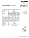
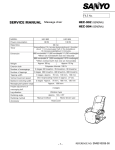
1
Nesis Installation Manual Kanardia March 29, 2013 © Kanardia d.o.o. Nesis installation manual – Initial release Nesis — Installation Manual Contact Information Publisher and producer: Kanardia d.o.o. Ulica heroja Rojška 70 SI-3000 Slovenia Tel: +386 590 12 521 Fax: +386 590 11 416 Email: [email protected] A lot of useful and recent information can be also found on the Internet. See http://www. kanardia.eu for more details. Copyright This document is published under the Creative Commons, Attribution-ShareAlike 3.0 Unported licence. Full license is available on http://creativecommons.org/licenses/by-sa/ 3.0/legalcode web page and a bit more human readable summary is given on http: //creativecommons.org/licenses/by-sa/3.0/. In short, the license gives you right to copy, reproduce and modify this document if: you cite Kanardia d.o.o. as the author of the original work. you distribute the resulting work only under the same or similar license to this one. Credits This document was written using TeTeX (LATEX) based document creation system using Kile integrated LaTeX environment running on Linux operating system. Most of the figures were drawn using Open Office Draw and Inkscape applications. Photos and scanned material was processed using Gimp. All document sources are freely available on request under the licence mentioned above and can be obtained by email. Please send requests to [email protected]. Revision History The following table shows the revision history of this document. Revision 1.0 Date March 2013 Description Initial release Document File NesisInstallation-100.pdf The document can be downloaded from http://www.kanardia.eu/downloads/nesis Initial release 2 © Kanardia 2013 Nesis — Installation Manual CONTENTS Contents 1 Introduction 4 1.1 Icons Used Trough the Manual . . . . . . . . . . . . . . . . . . . . . . . . . . 4 1.2 Nesis System Planning . . . . . . . . . . . . . . . . . . . . . . . . . . . . . . . 4 2 Nesis Display Installation 2.1 5 Installation to the Instrument Panel . . . . . . . . . . . . . . . . . . . . . . . 5 2.1.1 2.1.2 5 5 Nesis 8.0” Display . . . . . . . . . . . . . . . . . . . . . . . . . . . . . Nesis 5.5” Display . . . . . . . . . . . . . . . . . . . . . . . . . . . . . 2.2 Cable Clearance . . . . . . . . . . . . . . . . . . . . . . . . . . . . . . . . . . 5 2.3 Back Panel Connectors . . . . . . . . . . . . . . . . . . . . . . . . . . . . . . . 6 2.4 2.5 Power Connection – Connection to the Electrical System . . . . . . . . . . . . Pitostatic Connection . . . . . . . . . . . . . . . . . . . . . . . . . . . . . . . 8 8 2.6 Outside Air Temperature Installation . . . . . . . . . . . . . . . . . . . . . . . 9 2.7 Connection to the Audio System . . . . . . . . . . . . . . . . . . . . . . . . . 9 2.8 2.9 Connection to the CAN Network . . . . . . . . . . . . . . . . . . . . . . . . . GPS Antenna Installation . . . . . . . . . . . . . . . . . . . . . . . . . . . . . 10 10 2.10 ADS-B/Flarm Installation . . . . . . . . . . . . . . . . . . . . . . . . . . . . . 11 2.10.1 ADS-B . . . . . . . . . . . . . . . . . . . . . . . . . . . . . . . . . . . 11 2.10.2 Flarm . . . . . . . . . . . . . . . . . . . . . . . . . . . . . . . . . . . . 11 Initial release 3 © Kanardia 2013 Nesis — Installation Manual 1 1. Introduction Introduction First of all, we would like to thank you for purchasing our product. The Nesis system is a set of complex electronic devices and we strongly recommend to carefully read this manual before you start installing the Nesis system. The manual provides information about the installation of the Nesis system. Here we assume that you are familiar with the Nesis user interface system. Therefore, we also recommend reading the Nesis User Manual, before proceeding with the installation. 1.1 Icons Used Trough the Manual A few icons appear on the side of the manual, which have special meanings: This icon denotes information that needs to be taken with special attention. This icon denotes background information about the subject. This icon denotes an installation tip. 1.2 Nesis System Planning The Nesis system planning is described in a special document. Please, refer to the “Nesis Purchase Guide” document, which is available from our web site http://www.kanardia.eu. Initial release 4 © Kanardia 2013 Nesis — Installation Manual 2 2. Nesis Display Installation Nesis Display Installation This section covers the installation of the Nesis display. It also gives details how to connect to the pitostatic system, to other Nesis system components and to the electrical system. 2.1 Installation to the Instrument Panel Cut your instrument panel according to your Nesis display size using cut-out dimensions and cut-out templates given in the Appendix or http://www.kanardia.eu/downloads/nesis. In Appendix at the back of this document you can find the exact panel cut-out and mounting hole patterns with all required dimensions. Print the corresponding page on a hard paper. After printing, take a precise ruler or measuring tape and make sure, that printed sizes are correct. This procedure is necessary, because some printers or PDF rendering software may slightly adjust the document size, producing wrong cut-out dimensions. If you do not want to cut the panel yourself, you may consider to machine cut the opening in a local workshop using CNC equipment (a laser cutting machine is typically used). This is especially useful if you are making a complete rearrangement of your instrument panel. After cutting on a CNC machine make sure, that all the instruments fit into the new openings. You can powder paint the panel using non-reflective dark paint. This makes excellent results in practise. Please also note, that the paint layer makes holes slightly smaller and you should take this into account. We usually add extra 0.2 mm to all dimensions allowing for the paint thickness and we re-drill mounting holes with a 3.5 mm drill for Nesis 8.0” version and with a 4.5 mm drill for Nesis 5.5” version, in order to remove the paint inside the instrument panel holes. 2.1.1 Nesis 8.0” Display Nesis display is shipped with a set of mounting hardware (four screws and nuts). You can replace screws with more appropriate ones, just do not use rivets. Do not use screws with head larger than 5.5 mm in diameter. Nesis 8.0” is mounted from front. Fixing nuts are positioned at the back of the instrument panel and can be removed, if installation in aircraft requires so. Do not re-drill holes in the Nesis aluminium mask with a drill larger than 3.0 mm. 2.1.2 Nesis 5.5” Display Nesis 5.5” is mounted from the back of the instrument panel. First remove small plastic tip from both knobs. Use finger nail or thin screwdriver. When the tip is removed, the securing nut is exposed. Remove the nut and gently slide the knob from the axis. Finally remove the nut bellow the knob. See figure 1. Also remove two screws. This will allow the Nesis 5.5” to be installed. Position Nesis in the instrument panel and reverse this procedure to install the Nesis in place. 2.2 Cable Clearance The Nesis display requires about 6 cm additional clearance behind the display. This clearance is needed for connectors and cables. Figure 2 shows the photo of Nesis display taken from side, together with all cables and connectors. Initial release 5 © Kanardia 2013 Nesis — Installation Manual 2.3 Back Panel Connectors Figure 1: Remove the tip from knob (left), slide the knob from axis (middle), remove the nut bellow the knob (right). Figure 2: Side photo of Nesis display with all cables connected. Cables require about 6 cm additional clearance. 2.3 Back Panel Connectors All Nesis displays have the following ports on its back side: power, one USB port, four RS-485 ports, two CAN ports and audio output port. Additionally, there is one USB port on the front. Nesis Primary display hosts an AHRS device, GPS receiver and pitostatic sensors. They are all integrated on electronic circuit, called AIRU. AIRU requires additional ports for GPS antenna, static pressure, total pressure and outside air temperature. All these are routed to the Nesis back side as well. Nesis Primary display also has port for ADS-B Flarm connection. A Nesis display with the AHRS device integrated is hereinafter referred to as Nesis Primary display, while Nesis without AHRS is referred to as Nesis Slave. Figure 3 displays the back panel of a Nesis Primary and Nesis Slave display. Here is a list of connectors: 1. High speed USB port – in general any USB compatible device that Nesis can make use of, can be plugged into the USB port. Linux operating system and hardware specific drivers may not work with some USB devices that may normally work on a PC. Therefore we recommend, that you either buy such device from Kanardia, or that you test the device on Nesis before you buy it. Initial release 6 © Kanardia 2013 Nesis — Installation Manual 2.3 Back Panel Connectors Figure 3: Back side photo of Nesis Primary display with AHRS unit built-in (left) and Nesis Slave (right). At the time of writing, typical devices to use with this port are USB drives, cameras and USB to RS-232 converters. Nesis software is under continuous development and new devices are planned to be supported in the future. When more USB devices need to be connected to the back port, USB hub may be used, to provide more USB connections. 2. Two CAN ports – they are used to connect other CAN devices from the Nesis system. Connectors are equivalent so either one can be used to connect a CAN device. 3. Audio port – stereo audio output is used to connect to an intercom or similar audio system. At the time of writing, Nesis voice and audio messages are played. Future software releases may provide MP3 music support or even video support. In section 2.7 on page 9 you will learn more about audio port and connection schemas. 4. Four RS-485 ports – they are used to connect with devices via 485 protocol such as indicators or LX Cluster. 5. Power connector – provides power for the Nesis display and the CAN network. More about power connection is revealed in section 2.4. Nesis Primary display has the following additional ports: 6. Standard GPS antenna port – is used for external GPS antenna needed by the GPS receiver integrated on AHRS unit. More about GPS antenna installation is written in section 2.9 on page 10. 7. Static pressure port – must be connected to the static pressure tube. Section 2.5 on page 8 reveals more details. 8. Total pressure port – must be connected to the total pressure tube. Section 2.5 on page 8 reveals more details. 9. Outside air temperature port – connects to the Kanardia digital OAT probe. Details about OAT probe installation and connections are written in section 2.6 on page 9. Initial release 7 © Kanardia 2013 Nesis — Installation Manual 2.4 Power Connection – Connection to the Electrical System 10. ADS-B Flarm port – connects to the ADS-B and Flarm unit. 11. Other connectors – Nesis hardware and software is in constant development and is compatible with more and more units. Therefore we designed and added to Nesis back panel extra connectors for devices to follow in the near future. 2.4 Power Connection – Connection to the Electrical System The Nesis display must be connected to a 12 V DC standard aircraft power source. Additionally it can be connected to the backup battery – UPSU unit. The Nesis display consumes very little power (less than 10 W), which means about 0.8 A at 12 V. We recommend connecting Nesis using appropriately rated breaker or replaceable fuse on the power input. A 5 – 7.5 ampere fuse is appropriate. Make sure that all units share the same common ground. There should be none or minimal measurable voltage (up to 10 mA) between common ground and each unit ground, when all units are turned on. Otherwise your aircraft electrical system needs a good inspection. In Appendix at the back of this document you can find power connection schema for Nesis display. The Nesis display connects to the avionics power bus, where the complete bus must be switched on before any avionics can be used. Nesis is shipped with 1 m long power cable with 2 pin female connector on one side and unterminated solid lines on the other. Red line connects to the 12 V DC and blue line connects to the ground. If you find the 1 m power cable too long, you can shorten it to any length, saving some precious weight. When you use more than one Nesis display in the cockpit, repeat the connection procedure for the second display the same way as for the first one. 2.5 Pitostatic Connection In most avionics installations there are several instruments that need to be connected to the pitostatic system. A typical instrument panel has at least a mechanical airspeed indicator and altimeter. Nesis shares the same pitostatic source with them. Pitostatic consists of static pressure tubing and total pressure tubing. In order to connect to the static source, cut the static tube on an appropriate place and insert plastic T junction. Cut some new tube to length and connect T junction with the Nesis static port. We recommend use of hose clamps on all junctions and connections to secure against slippage and to reduce chance of pressure leak. Use the procedure above for the total pressure tube as well: cut the total pressure tube, insert T junction, connect T junction and Nesis total port and secure connections using hose clamps. We strongly recommend labeling each tube before connecting to Nesis or any other instrument. If you ever have to remove Nesis from the instrument panel, this will help a lot when you will reinstall it. Initial release 8 © Kanardia 2013 Nesis — Installation Manual 2.6 2.6 Outside Air Temperature Installation Outside Air Temperature Installation Although the OAT probe is a simple element in the Nesis system, its installation requires some attention. Outside air temperature (OAT) probe is shipped with the Nesis Primary display. This is a digital temperature sensor inserted into a threaded aluminium tube. The default OAT cable length is 1.5 meters, but other lengths are available on request. OAT information is required to calculate the true airspeed from the indicated airspeed and altitude, as well as to provide you with the outside air temperature information. In order to provide accurate measurements, the OAT probe must be installed on a proper place, where the probe is not exposed to the disturbing sources of heat: engine heat and exhaust heat, direct sunlight, heated air exited from cabin. We also do not recommend installing the probe in the cabin area, since the elevated temperature in the cabin may influence the back side of the probe, though such influence is usually small. Please follow these steps to install the OAT probe: 1. Locate a spot in the aircraft taking into account the considerations from above and drill a ϕ 8 mm hole. 2. Remove the external nut from the probe, but keep the washer, internal nut and plastic insulation tube on the probe. 3. Install the probe into the hole from the interior. Guide the cable trough the aircraft to the Nesis Primary display back side. 4. Apply some lock-tight and thread the external nut to the probe. The lock-tight is necessary to avoid losing the cap due to vibrations. 5. Tighten the internal nut so that the probe sits firmly and apply lock-tight on the nut. Do not over tight it. 6. Slide the plastic insulation tube over the exposed threads of the probe and cover as much threads as possible. Shrink the tube using hot air blower. Do not use open flame. Plastic insulation (shrink) tube also serves as internal isolation. 2.7 Connection to the Audio System Nesis display is shipped with an audio connector cable. One end of the cable has a male stereo audio jack which fits into Nesis display. The other end has two male RCA plugs, which fit into avionics audio system (radio station, transponder ...). Audio output provided by NESIS is amplified. Audio power output is 0.25 W@8 Ω and is suitable to play sounds on speakers directly. The voltage swing of the audio output is 5 V peak to peak. Initial release 9 © Kanardia 2013 Nesis — Installation Manual 2.8 Connection to the CAN Network Figure 4: Inserting the OAT probe (left), cap is in place, tighten the internal nut, slide the insulation tube (right). When you install Nesis Slave display beside Nesis Primary display, you need to prevent duplicate audio warnings (one from the Primary and the other from the Slave display), which could be very annoying. This can be done by turning the audio alerts off in the Nesis Slave display. As an alternative, you may consider not to connect the Nesis Slave display to the aircraft audio system at all. 2.8 Connection to the CAN Network Both CAN ports found at the back of the Nesis display are equivalent. In most standard configurations, one CAN port is used to connect Daqu (engine monitoring unit), while the other is unused or connected with Magu (electronic magnetic compass) or to Nesis Slave display. Just to remind you, Daqu and Magu units have all 120 Ω CAN network terminator resistors to start and terminate the network. 2.9 GPS Antenna Installation Please, consider mounting the GPS antenna using the following recommendations: Find a good spot in a cabin where the antenna is able to “see” blue sky during most of the aircraft movement. Such a good spot can be usually found on the top of the instrument panel cover, just below the canopy. Mounting surface should be flat, clean and rigid. Avoid close proximity to any transmitting antennas like radio stations, transponders or any other active GPS antennas (GPS antennas may interfere each other). Antenna must not be covered or obstructed by metals (metals sheets, rods) or any other conductive material (like carbon fibres). The supplied antenna length is 1.2 meter, but other lengths are available on request. The triangle/GPS text on antenna must point upwards – to the sky. For the installation, use self adhesive tape and fix the antenna on a rigid and clean surface. The supplied antenna is not intended to be installed on the aircraft exterior. If you need to install the antenna on the external surface, search a suitable antenna in your local avionics shop. Any 3.3 V active antenna with SMA male connector can be used. The AHRS unit, which is hosted by the Nesis Primary display, has an internal super capacitor, which provides power for the GPS for about 14 days after the last flight. It enables so called Initial release 10 © Kanardia 2013 Nesis — Installation Manual 2.10 ADS-B/Flarm Installation hot-start of the GPS module. A hot-start means that GPS constellation almanac is kept in the GPS module memory after the Nesis was powered down. Note: On the first start up, on a cold-start or when Primary Nesis is moved for a significant distance without receiving GPS signal (shipping across the Globe), GPS receiver needs to download almanac from the constellation. This requires a good GPS signal and may take a few minutes. 2.10 ADS-B/Flarm Installation Connection schema for Nesis display and ADS-B/Flarm can be find in Appendix at the back of this document. Following sections describe the installation of the units. 2.10.1 ADS-B Mount ADS-B receiver on a flat surface at the back of the instrument panel. Find appropriate place and use 3.5 mm drill to make four mounting holes. Use screws to fix ADS-B in place. Use washers, if installation requires so. Guide the stick antenna cable from ADS-B to the top of the instrument panel cover and mount stick antenna there. 2.10.2 Flarm Flarm designated position is on the back of the Nesis display. Use screws to fix it in place. For powering, connect red wire to “+” pole and blue wire to the ground. Connect GPS antenna according to recommendations in section 2.9. Guide the stick antenna cable from Flarm to the top of the instrument panel cover and mount stick antenna there. Remove Nesis from instrument panel, if installation in aircraft requires so. Figure 5 illustrates installed Flarm. Flarm display is shipped with Flarm unit. Pick a spot on instrument panel and use a 3.0 mm drill to make two mounting holes. Use shipped screws and fix Flarm display on instrument panel. Figure 5: Flarm installed on the back panel of the Nesis display. Initial release 11 © Kanardia 2013