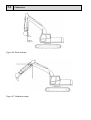
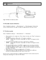
1
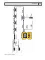
INSTA
ALLATION MA
ANUAL
Xsite E
EASY Sy
ystem
Please completely re
ead this operaation manual and
a
the
ned safety insttallations and note all given
n information
contain
before usage.
Keep a vailable for fu
urther consideeration!!!
ENGLISH
Original installation manual
Order-No.: 10-02-02323
Date: 03.2013
Complying with version 1.00 / 14.11.2012
Please handle this installation manual confidentially. It is intended only for use by
persons involved with the product.
The text and graphics of this manual have been elaborated with the greatest
possible care. However, we may not be held liable for possible errors and failure
effects.
Should you wish to make suggestions regarding the arrangement of this manual or
point out possible errors, please contact your local dealer. We will gladly take up
any of your ingenious ideas and suggestions.
Some company and label names are subject to label-, patent- or trade-mark
protection.
All rights reserved. This document must not be duplicated or transferred for any
purpose whatsoever without MOBA’s written consent, irrespective of the way or the
means that are used.
Copyright:
MOBA Mobile Automation AG
Kapellenstraße 15
65555 Limburg
Internet: www.moba.de
Table of contents
3
1. Table of contents
1. Table of contents ................................................................................. 3 2. 2.1. 2.2. 2.3. 2.4. 2.5. Introduction .......................................................................................... 4 Safety instructions ................................................................................. 6 Product overview .................................................................................. 10 Handling of the system .......................................................................... 12 Transportation and storage .................................................................... 12 Support and maintenance ...................................................................... 12 3. 3.1. 3.2. 3.2.1. 3.2.2. 3.2.3. 3.2.4. 3.2.5. 3.3. 3.3.1. Installation of components ................................................................. 13 Components inside the cabin ................................................................. 13 Inclination sensors and laser receiver .................................................... 14 Tilt bucket sensor .................................................................................. 17 Bucket sensor ....................................................................................... 20 Laser receiver ....................................................................................... 22 Stick, main boom, and extra boom sensors ............................................ 22 Frame sensor ........................................................................................ 24 Finalising the installation ....................................................................... 25 Powercord ............................................................................................ 25 4. 4.1. 4.2. 4.3. 4.4. 4.5. Installation data................................................................................... 27 Bucket lengths ...................................................................................... 27 Linkage lengths ..................................................................................... 28 Laser receiver lengths ........................................................................... 29 Boom lengths ........................................................................................ 30 Rotation centre point offsets .................................................................. 30 5. 5.1. 5.2. 5.3. 5.4. 5.5. 5.6. 5.7. 5.8. 5.9. Calibration ........................................................................................... 31 Frame sensor calibration ....................................................................... 31 Stick sensor calibration ......................................................................... 32 Main boom sensor calibration ................................................................ 36 Extra boom sensor calibration ............................................................... 37 Boom line accuracy test ........................................................................ 37 Bucket mount calibration ....................................................................... 38 Quick coupler ........................................................................................ 38 Linkage ................................................................................................. 39 Completing the calibration ..................................................................... 39 6. Declarations of Conformity ................................................................. 40 4
Introduction
2. Introduction
This document is the installation manual of the Vision 3D machine control system.
Please completely read this manual and the contained safety installations and note
all given information before usage. Keep the manual available for further
consideration.
Conformity to directives and regulations
This product is in conformity with EU's EMC (2004/108/EC), RoHS (2002/95/EC),
and WEEE (2002/96/EC) directives and REACH (2006/1907/EC) regulation. This
product may not be disposed of together with unsorted household waste, it must be
collected separately.
Disclaimer
•
•
•
•
•
•
•
•
The manufacturer excludes any liability for damages caused by:
Inappropriate assembling and installation
Non-observance of the installation manual
Non-intended and improper use
Use beyond operation limits
Deployment of insufficiently qualified and trained personnel
Use of unauthorized spare parts and accessories
Rebuilding of the product
Installation manual
This installation manual contains basic information to be considered when using and
maintaining the product. Observing all security installations and guidelines given
here is indispensable for secure operation. Therefore this installation manual has to
be read and applied without fail by any person assigned with working processes at
the machine, such as operation, disturbance elimination and maintenance.
In
ntroductiion
5
This ma
anual is a part of the
e product and as th
he case may
m be hass to be pa
assed to
third perrsons or following
f
owners.
o
Itt has to be
e permane
ently keptt at the us
sage site
and be a
available for the op
perating pe
ersonnel. Furtherm
more the loocal accident
preventiion regula
ations for the
t
produ ct’s opera
ational are
ea, the geeneral safe
ety
regulatio
ons as we
ell as the manufactu
m
urer’s safe
ety regula
ations havve to be observed.
The prod
duct is avvailable wiith diverse
e sensor combinati
c
ons. In caase your system
s
is
not equiipped with
h all senso
ors or oth er compo nents, the
eir descripption is a matter of
unimporrtance. Du
ue to multiple possiible applic
cations, th
he functio ns of the product in
n
this man
nual will be
b explained at the example of an excavator.
e
the
e correctn
ness and up-to-date
eness of tthis installation
We are eager to ensure
erve our te
echnologiccal advan
nce, it can be necesssary to undertake
manual. To prese
modifica
ations of t he produc
ct and its operation
n without prior
p
noticce which under
u
circumsttances ma
ay not corrrespond tto this ma
anual. In that case yyour locall dealer will
w
provide you with a new ma
anual. We exclude liability
l
for disturbaances, failures and
resulting
g damage
es.
The textt and grap
phics of th
his manua
al have be
een elaborrated with the greattest
possible
e care. Ho
owever, we may nott be held liable for possible eerrors and
d failure
effects. Should yo
ou wish to
o make su
uggestions
s regardin
ng the arraangementt of this
o possible errors, please co
ontact you
ur local deealer. We will gladl y
manual or point out
take up any of yo ur ingenio
ous ideas and sugg
gestions.
Explana
ation of symbols
s
nstallation
n manual warning
w
n
notices are
e marked by symbools. Underr all
In this in
circumsttances ob
bserve the
ese notice
es and pro
oceed care
efully to pprevent ac
ccidents,
persona
al injuries, and mate
erial dama
ages.
In
ndicates a hazardo
ous situattion. If no
ot avoided
d, could result in
de
eath, serious injurry, or matterial dam
mages.
NOTE!
Empha sizes use
eful tips a
and recom
mmendattions as w
well as information
n
referrin
ng efficient and fa ilure-free
e operatio
on.
6
Introduction
2.1. Safety instructions
This section outlines all important safety matters referring the personnel’s optimal
safety as well as failure-free operation. These installations shall enable users to
recognize potential risks of use and as possible prevent them in advance. Every
user has to understand and observe these installations.
Conventional use
Vision 3D has been exclusively designed and constructed for conventional use as
described here. Positioning the measuring point of the tool (e.g. bucket, blade) of a
construction machine with the help of gravitation sensors, laser receiver, GNSS
receiver(s) or other positioning devices. Indication of the position of the measuring
point to the user or to a third party system. Comparison of the position of the
measuring point with various types of reference information.
Any other use not listed here as well as any application not complying with the
technical data is not conventional and inappropriate.
Inappropriate use
•
•
•
•
•
•
•
•
•
•
•
•
Non-conventional use
Exceeding of the limit values given on the data sheet
Use of the product without installations
Use of the product beyond the limits of use
Invalidation of safety equipment
Removal of indicating or warning labels
Opening of the product
Rebuilding or alteration of the product
Commissioning of the product after misappropriation
Use of the product in spite of obvious defects or damages
Use of the product with unauthorized accessory from foreign manufacturers
Use of the product at insufficiently secured construction sites
Introduction
7
Alteration and rebuilding of the product
To prevent risks and ensure optimal performance neither alterations or attachments
or rebuildings of the product may be carried out without the manufacturer’s explicit
permission.
The operator’s responsibility
The product is used in the industrial sector. Therefore the operator of the product is
liable to the legal responsibilities for operational safety. Besides the operational
safety installations in this manual, the safety, accident prevention, and
environmental protection regulations valid for the operational area of the product
have to be observed.
Particularly applying:
The operator has to inform himself about the current operational safety regulations
and, in a risk assessment, detect additional risks that are caused by the special
working conditions at the usage site of the product. These then have to be
implemented in the form of directives. These directives have to be kept near to the
product and permanently be available for the persons working with it.
The operator has to clearly define the personnel’s responsibilities referring the
appliance.
The operator has to ensure that the installation manual’s content is fully understood
by the operating personnel.
The statements of the installation manual have to be observed thoroughly and
unrestrictedly.
The operator has to ensure that all maintenance, inspection and assembling
processes are carried out by qualified specialized personnel, which have informed
themselves sufficiently by closely studying the manuals for the product’s operation.
The operator informs the manufacturer or the authorized dealer if any safety defects
occur at the product or during operation.
8
In troductio
on
Sp
pecial ris ks
s caused by electrric curren
nt!
Risks
When
n working close to e
electric sy
ystems (e..g. overheead powerrlines),
there is dangerr to life du
ue to elec tric shock
k. Keep suufficient sa
afety
distan
nce to electric syste
ems.
Movi ng compo
onents!
Keep persons away from
m the mac
chine’s and the tooll’s working
g
range
e. Remove
e objects ffrom the machine’s
m
s and the tool’s worrking
range
e. Do not interfere
i
w
with the moving
m
com
mponentss during
opera
ation
m
p
parts!
Over lapping machine
equently assemble
a
d system components (e.g. G
GNSS ma
asts)
Subse
can overlap
o
the
e typical m
machine dimension
d
s. This caan lead to
injurie
es and ma
aterial dam
mages
Risk of injury caused b
by malfun
nction!
Unco ntrolled machine
m
acctions cau
used by th
he malfun ction of a
syste m component can lead to se
evere pers
sonal injurries in the
e
e or caus e material damage . Ensure that
t
mach ine’s working range
m
is operated
d, controlle
ed and ins
spected bby a qualiffied
the machine
and experience
e
ed operato
or, who has to be able
a
to indduce emergency
meassures, e.g.. an emer gency sto
op.
Lack ing instru
uction!
Lacki ng or insu
ufficient in
nstruction can lead to operatting errors
s or
T
can llead to se
evere pers
sonal injurries as we
ell as
incorrrect use. This
severre materia
al and envvironmenta
al damage
es. Obserrve the
manu
ufacturer’s
s safety in
nstallation s and the operator’’s directiv
ves.
In
ntroductiion
9
ury cause
ed by ins
sufficient safeguarrding!
Riisk of inju
In sufficient safeguar ding of th e construction site and the
co
omponent’s location
n, e.g. of the
t
laser emitter, ccan lead to
o
ha
azardous situationss in traffic and at the constru ction site. Ensure
ng of the construction site. E
su
ufficient sa
afeguardin
Ensure sufficient
sa
afeguardin
ng of the ssingle com
mponents’’ locationss. Observe the
co
ountry-spe
ecific safe
ety and ac
ccident pre
evention rregulation
ns as well
ass the curre
ent road t raffic regu
ulations.
sed by fau
ulty meas
surementt results!
Riisks caus
Fa
aulty measurementt results due to use of a droppped product,
an
nother illegitimate d
demand o r an altera
ation can lead to se
evere
m aterial damages. D
Do not use
e obviously damageed products. Before
e
re
eusing a dropped co
omponentt, carry ou
ut a checkk measure
ement.
Riisk of inju
ury cause
ed by unrreadable signs!
In the cours
se of time
e, labels a nd symbo
ols on the product can
c
get
di rty or get unrecogn
nizable du
ue to otherr events. Due to im
mmoderate
e
m echanicall effects la
abels and symbols can be deetached. Always
A
ke
eep safety
y, warning
g and ope ration insttallations in a well readable
st ate. Regu
ularly checck the adh
hesivenes
ss of the laabels and
d symbols
on
n the prod
duct. Do n ot remove
e labels and symbools from th
he
prroduct.
ury cause
ed by ina
appropriate dispossal of the product!!
Riisk of inju
W
When
burniing plasticc parts, to
oxic gases
s that can cause illn
nesses
em
merge. Dis
spose the
e product properly according
a
to the current
na
ational country-spe cific dispo
osal regulations. Caareless diisposal
m ight also enable
e
un
nauthorize
ed persons to improoperly use
e the
prroduct. In doing so these perrsons and/or third ppersons ca
an be
se
everely injjured and also pollu
ute the en
nvironmennt. At all times,
prrotect the product a
against the
e access of unauthhorized pe
ersons.
10
Introduction
Proceeding in case of danger and accidents
•
•
•
•
•
•
•
•
•
•
•
•
Preventive measures
Always be prepared for possible accidents or the event of fire.
Keep first-aid equipment (ambulance box, blankets etc.) within reach.
Familiarize the personnel with accident notification and first-aid equipment as
well as emergency services.
Keep the access routes clear for emergency vehicles.
If the event occurs, proceed appropriately
Immediately put the product out of action by switching the power off.
Induce first-aid-measures.
Recover persons out of the hazard zone.
Inform the responsible person at the usage site.
Alarm a doctor and/or the fire brigade.
Keep the access routes clear for emergency vehicles.
2.2. Product overview
Xsite EASY is a machine guidance system for excavators. Xsite EASY indicates the
position of the measuring point compared to a reference level.
The system contains the following components by default (Figure 1):
• Display unit
• Connection box for LED display
• Gravitation sensors for bucket, dipper stick, main boom, and frame
The system can be expanded by adding the following optional accessories (Figure
1):
• Tilt bucket sensor
• Dual block boom sensor
• Laser receiver
• LED display
Introduction
Figure 1. System diagram
11
12
1
In troductio
on
2.3. Hand ling of the
t
system
Th
he displayy is not co
ompletely waterproo
w
of. If the display
d
or other com
mponents are
taken awayy from the constructtion mach ine, a carrrying case should be used. Make
su
ure that th e compon
nents are clean and
d dry befo
ore placing
g them in the carrying
ca
ase. Also m
make sure
e that the carrying case is cl ean and dry.
d
2.4. Trans
sportatio
on and storage
s
W hen takin g the equ ipment to the usag e site or in
i the field
d, always ensure th
hat the
prroduct is t ransporte
ed in secured and s uitable co
ontainers. Never traansport th
he
prroduct loo sely in the
e car. The
e product’ s function
n can be severely
s
hharmed by
y hits
an
nd thrusts . In case of transpo
ortation byy railway, plane or ship, alwaays use th
he
orriginal pacckaging, trransport containers
c
s and tran
nsport box
xes. The ppackaging
prrotects the
e product against hits and vib
brations.
nly store tthe produ ct in well aired, dryy rooms. During
D
sto
orage, pro tect it aga
ainst
On
da
ampness, and prefe
erably use
e the origi nal packa
aging. Avo
oid strong thermal
flu
uctuation d
during sto
orage. Incipient form
mation of water con
ndensatio n can harrm the
prroduct’s fu
unction.
2.5. Supp ort and mainten
nance
Ma
anufactur er or dealler will pro
ovide the maintena nce services. Instaallation an
nd
se
ervice of th
he producct should be carried
d out only by trained and quaalified perrsonnel.
For s afety reas
sons (risk of high voltages), only repreesentative
es of
the manufactur
m
rer are all owed to open
o
the housings.
h
Installa
ation of ccomponen
nts
13
3
3. Insttallation of co
ompone
ents
The cha
apters belo
ow provide informa
ation abou
ut installation of thee compone
ents
3.1. Co
omponen
nts insid
de the c abin
When m
mounting t he display
ys, notice the follow
wing preca
autions:
•
•
•
•
•
•
D isplay
D isplay
D isplay
D isplay
D isplay
D isplay
ould
sho
sho
ould
sho
ould
sho
ould
sho
ould
sho
ould
be mounted so
o that it is easily reachable bby the ope
erator.
not block
b
the vview outsi de.
not block
b
the vview to ma
achine's integrated display.
not prevent
p
the
e front win
ndow from
m openingg.
not re
estrict mo
oving of op
perator's seat.
s
not re
estrict acccess to the steering
g wheel orr joysticks
s.
Attach t he Xsite EASY
E
disp
play and tthe XD2 LED
L
displa
ay to the ffront or sid
de window
w
by suctio
on cups ( Figure 2).. Before a
attaching the
t
suction cup, maake sure that
t
the
window is clean (use
(
for ex
xample iso
opropyl a lcohol if needed)
n
a nd warm (warm it up
u
carefullyy if neede d).
Figure 2.. Example of the mou
unting placce of the Xsite
X
EASY display annd the XD2
2 LED
display
he XD2 co
onnection box for e
example b ehind the operator''s seat by
y screws or
o
Mount th
tape (Ve
elcro, Dua
al lock). Make
M
sure that all ca
ables can reach to the conne
ection boxx
and thatt the conn
nection bo
ox does no
ot restrict moving of operatorr's seat. Make
M
sure
e
that the plastic co
overs of th
he cabin ccan be detached without unm
mounting the
t
connect ion box.
14
1
In stallation
n of comp
ponents
3.2. Inclin
nation se
ensors and
a
lase
er receiv
ver
Inclination ssensors are
a mounte
ed on the moving parts
p
of the excavattor. Senso
ors are
lab
belled wit h the follo
owing iden
ntification numbers
s (Figure 3):
3
101.
102.
103.
104.
105.
106.
107.
B ucket sen
nsor
or
S tick senso
M
Main boom
m sensor
N
Not used
F rame sen sor
E xtra boom
m sensor (if
( excava tor is equ ipped with dualblocck boom)
T ilt bucket sensor (o
optional)
gure 3. Sensor IDs
Fig
with a PC software
s
provided
p
bby Novatrron. For
It is possibl e to chan ge the sensor ID w
xample if rreplacing a broken sensor w
with a new one, the ID of the new sens
sor must
ex
be
e the same
e as the I D of the broken
b
se nsor.
It is not nee
eded to al ign the se
ensors witth the boo
om lines (tthe line beetween tw
wo pivot
oints). Sofftware cal ibration corrects th
he deviatio
on from th
he boom liine. Howe
ever,
po
so
ome senso
ors require
e more prrecise mo unting tha
an others.
Se
ensors are
e mounted
d in the fo
ollowing o rder:
1.
2.
3.
4.
5.
6.
Tilt bucket se
ensor (optional)
Buc ket senso
or
Stic k sensor
n boom se
ensor
Main
Extrra boom sensor
s
(op
ptional)
Fram
me senso r
Installa
ation of ccomponen
nts
15
5
The sen
nsors shou
uld be mounted whe
ere the ca
able from the previoous senso
or ends in
order to avoid loo
ose cable on the bo
oom. If the
e bucket is
s very greeasy, insta
all the tilt
d staining of the cab
bin during
g the rest of the installation
bucket ssensor lasst to avoid
procedu
ure.
In most cases sen
nsors are mounted by using bolts. However, soome mach
hine
manufaccturers do
o not acce
ept drilling
g of the bo
oom. In those casess, sensors
s are
attached
d to moun
nting plate
es by scre ws. Moun
nting plate
es are wel ded on th
he boom.
m
ment axes in the sen
nsor (Figu
ure 4).
There a re three measurem
Figure 4.. Measurem
ment axes
16
Installation of components
Sensors can be mounted to several different positions (Figure 5). Not all mounting
orientations are possible for all sensors. See chapters 3.2.1 – 3.2.5 for details
Figure 5. Mounting orientations (arrow points forward)
Installa
ation of ccomponen
nts
17
7
3.2.1. Tiilt buckett sensor
M ovements
s of the bu
ucket and bucket ac
ccessorie s have to be
hecked be
efore insta
alling the sensor
s
or sensor caables. Mo
ovements
ch
off the cable
e have to be checke
ed after th
he installaation.
Th
he moving
g part of th
he cable has
h to be covered bby a shield.
Sh
hielded ca
able from the bucke
et sensor has to bee connecte
ed with
on
ne or more
e fastenerrs. Mount the first fastener
f
aapproxima
ately
15
5 cm from the sens or.
m
o
on a tilt ro
otator, tilting quick ccoupler orr tilting
Tilt buckket senso r can be mounted
bucket.
Possible
e mountin g orientattions for th
he tilt buc
cket senso
or are:
•
A 1: left side
e, measurrement axxis A pointting forwa
ard
•
B 1: on the top, meas
surement axis A po
ointing forw
ward
•
B2
2: on the top, meas
surement axis A po
ointing righ
ht when loooking fro
om the cab
bin
•
B3
3: on the top, meas
surement axis A po
ointing bac
ckward
•
B4
4: on the top, meas
surement axis A po
ointing leftt when loooking from
m the cabi n
(F
Figures 8 and 9)
•
C 1: right si de, measurement a
axis A pointing forw
ward
•
D 1: at the bottom,
b
measureme
m
ent axis A pointing forward
•
D 2: at the bottom,
b
measureme
m
ent axis A pointing left whenn looking from
f
the
ca
abin (Figu
ure 7)
•
D 4: at the bottom,
b
measureme
m
ent axis A pointing right wheen looking from the
ca
abin
If possible, mount th e sensor in a safe place. A sshield (forr example
ou
ut of steel) can be m
made for the
t
senso
or, if need ed.
NOTE!
Fo
or an easy
y access tto the sen
nsor conne
ector, it s hould be close to
th e hydraulic hose co
onnectors
s of the tiltt rotator.
NOTE!
Al ways align the tilt b
bucket se nsor eithe
er with thee boomline or in a
wa
ay that is forms a 9
90° angle with the boom
b
(Figgure 6). De
eviation of
o
+//- 1° can be
b tolerate
ed. Howev
ver, the smaller thee deviation
n, the
be
etter the measurem
m
ment resultt.
18
1
In stallation
n of comp
ponents
Fig
gure 6. Alig
gnment of the tilt buc
cket senso
or
gure 7. Tiltt bucket sen
nsor on the tilting part o
of the tilt rottator, inside
e the cover pplate (moun
nting
Fig
oriientation D2
2). Mounting
g place dep
pends on the
e manufactturer of the tilt
t rotator. IIn this exam
mple the
sensor is mou
unted upside down.
Installa
ation of ccomponen
nts
et sensor on
o a tilting q
quick coup
pler (mounting orientaation B4)
Figure 8.. Tilt bucke
Figure 9.. Tilt bucke
et sensor on
o a tilting bucket (mo
ounting orientation B
B4)
19
9
20
2
In stallation
n of comp
ponents
3. 2.2. Buck
ket senso r
ements of the bucke
et and buc
cket acces
ssories haave to be
Move
checkked before
e installing
g the sen sor or sen
nsor cablees. Movem
ments
of the
e cable ha
ave to be cchecked after
a
the in
nstallationn.
The moving
m
pa
art of the ccable has to be cov
vered by a shield.
Shield
ded cable
e from the bucket se
ensor has
s to be connnected with
w
one or
o more fasteners. M
Mount the
e first faste
ener apprroximately
y
15 cm
m from the
e sensor.
ucket senssor can be
e installed
d on quickk coupler or linkage
e.
Bu
Po
ossible mo
ounting orrientations
s for quickk coupler installatio
on are:
• A1: le
eft side, measurem
m
ent axis A pointing to the bu
ucket tip (F
Figure 10)
• B1: o
on the top,, measure
ement axiss A pointin
ng to the bucket tipp
• B4: o
on the top,, measure
ement axiss A pointin
ng left when lookin g from the
e cabin
• C1: riight side, measurem
ment axis A pointin
ng to the bucket
b
tip
W hen insta lling the sensor
s
on the quickk coupler, it is not necessary
n
y to align the
t
se
ensor exacctly with t he line fro
om the bu cket pin t o the bucket tip (Fiigure 10). Bucket
ca
alibration ccorrects t he deviatiion from t he line. However,
H
the
t
deviattion should be as
sm
mall as po
ossible. No
ote that when
w
chan ging the bucket,
b
the deviatioon also ch
hanges.
Fig
gure 10. In
nstallation on
o the inne
er or outerr surface off the quick coupler (m
mounting
orientation A
A1)
Installa
ation of ccomponen
nts
21
1
Possible
e mountin g orientattions for liinkage ins
stallation are:
a
•
A 1: left side
e, measurrement axxis A pointting forwa
ard (Figuree 11)
•
B 1: on the top, meas
surement axis A po
ointing forw
ward
•
C 1: right si de, measurement a
axis A pointing forw
ward
When in
nstalling th
he sensorr on the lin
nkage, ali gn the sensor with the line between
b
th
he
linkage pins withi n an accu
uracy of + /- 10°.
uter surfac
ce of the lin
nkage (mo unting orie
entation A1
1)
Figure 11. Installation on the inner or ou
22
2
In stallation
n of comp
ponents
3. 2.3. Lase r receive r
aser receivver is mo unted con
nnectors p
pointing do
ownwards
s on the leeft side off the
La
stiick aligne d exactly with the line betwe
een the st ick pin an
nd the buccket pin (F
Figure
12
2). Laser rreceiver should
s
be mounted in a shelttered place if possibble. Laserr
receiver sho
ould be mounted
m
on the lowe
er part of the stick, so that itt is not needed to
liftt the transsmitter un
nnecessarily high.
Fig
gure 12.La
aser receivver
3. 2.4. Stick
k, main bo
oom, and extra bo
oom sensors
ossible mo
ounting orrientations
s for the sstick, main
n boom, and
a
extra boom sen
nsors
Po
arre
•
A1: le
eft side, measurem
m
ent axis A pointing to the bu
ucket (Figuure 13)
•
C1: r ight side, measurem
ment axiss A pointin
ng to the bucket
b
•
C3: r ight side, measurem
ment axiss A pointin
ng to the cabin
c
If the boom consists of two pa
arts, extra boom is the
t
part th
hat is closser to the cabin.
Al ign the se
ensor with
h the boom
m line with
hin an acc
curacy of +/- 10°. T
The sensor should
e mounted
d in a she ltered place if posssible. To avoid
a
harm
mful accel erations, the
be
se
ensor shou
uld be mo
ounted as close to sstick/boom
m pin as possible.
p
Installa
ation of ccomponen
nts
23
3
Figure 13
3. Stick sensor (mounting orien
ntation A1))
NOTE!
It is not allo
owed to m
mount the main boom or extraa boom se
ensor on
th e narrowing part off the boom
m (Figure 14).
4. Main bo
oom and ex
xtra boom sensor
Figure 14
Ch
heck the movemen
m
ts of the cable
c
after installattion.
24
2
In stallation
n of comp
ponents
3. 2.5. Fram
me sensorr
ossible mo
ounting orrientations
s for the fframe sen
nsor are
Po
•
A1: le
eft side, measurem
m
ent axis A pointing to the bu
ucket
•
B1: o
on the top,, measure
ement axiss A pointing to the bucket (F
Figure 15)
•
C1: r ight side, measurem
ment axiss A pointin
ng to the bucket
b
d be aligned exactlyy with the boom centre line. Maximum
m
Frrame senssor should
ac
cceptable deviation from the line is +/-- 1°. Howe
ever, the smaller thhe deviatio
on, the
be
etter the m
measurem
ment resultt.
Be
est mountting positio
on is on the top of the mach ine and very near tto the rota
ation
ce
entre of th e machin e. When mounting
m
on the to p of the machine,
m
eensure tha
at cover
pla
ates are n
not vibrati ng with en
ngine revo
olutions. Optional
O
mounting
m
positions are
en
ngine area
a floor or cabin
c
floo
or as long as the ca
abin is tilting along tthe frame
e of the
ma
achine.
gure 15. Frame senssor, mountiing orienta
ation B1
Fig
Installa
ation of ccomponen
nts
25
5
3.3. Fin
nalising the insttallation
n
Take the
e cables from
f
devic
ces that a re mounte
ed outside
e the cabi n into the
e cabin
through one inlet .
The cab
bles can b e taken in
nto the ca bin for ex
xample by using onee of the fo
ollowing
options:
•
H oles unde
erneath the bottom cover
•
La
amp cable
e holes
•
Pe
edal holess
o not drill any holess to the ca
abin! The cabin is cconsidered as
Do
sa
afety equipment.
3.3.1. Po
owercord
d
The Xsitte EASY system
s
requires 24 VDC input voltage
e. Power ssupply sho
ould be
able to p
provide 1 A at
24 V.
NOTE!
In stall 12 V to 24 V cconverter to machin
nes with 1 2 V batte
ery.
e the fuse from the fuse hold er before installing the poweer cord. The fuse will
w
Remove
be put b
back after all compo
onents an
nd cables have been installedd.
Connectt plus (red
d) to the main
m
powe
er switch of
o the machine (Figgure 16).
Alternat ively conn
nect plus (red) stra ight to the
e battery output
o
(Fi gure 17). Connect
ground ((yellow) to
o the mac
chine chasssis.
Figure 16
6. Wiring diagram,
d
pllus to mac hine's main power sw
witch, grouund to mac
chine chasssis
26
2
In stallation
n of comp
ponents
Wiring dia
agram, plu
us to mach
hine's batttery, grou
und to macchine cha
assis
Fi gure 17. W
Affter the po
ower cord has been
n connecte
ed to a po
ower supp
ply, conne ct the other end
to the displa
ay.
The Xsite
X
EASY power ccable mus
st be alwa
ays equippped with a fuse.
Instaallation da
ata
27
7
4. Insttallation data
Lengthss must be measured
d precisel y with 1 mm
m accura
acy unlesss otherwis
se stated.
e the leng
gths and write
w
them
m down.
Measure
Machine
e coordina
ates (X, Y, Z) are e xplained in Figure 18.
8. X, Y and
d Z coordin
nates of th e machine
e
Figure 18
4.1. Bu
ucket len
ngths
Measure
e bucket l ength from
m the cen
ntre point of the low
west stick pin to the
e bucket ti p
(Figure 19). Meassure left bucket
b
wid
dth and rig
ght bucket width. If the tilting
g bucket iss
used, al so measu
ure the quick couple
er value.
9. Bucket measures:
m
1) Buckett length, 2)) Left width
h, 3) Right w
width, 4) Quick
Q
coup
pler
Figure 19
28
2
In stallation
n data
4.2. Linka
age leng ths
Lin
nkage len
ngths are measured
d if the bu cket sens
sor has be
een mountted on the
e linkage
(Figure 20) . Linkage paramete
ers are me
easured frrom the ce
entre poinnts of the pins.
gure 20. Liinkage lengths
Fig
Instaallation da
ata
29
9
4.3. La ser rece
eiver len
ngths
Measure
e X offset , Y offset and Z offfset.
X offset is measu
ured from the centre
e line of th
he laser receiver too the centre line of
the stickk. X offsett can be calculated
c
by meas uring the thicknesss of the stiick, dividin
ng
the mea
asure by tw
wo and ad
dding 70 m
mm to the
e value. Va
alue is neegative, be
ecause
laser recceiver is mounted
m
on
o the leftt side of th
he stick (F
Figure 21)).
Y offset is measu
ured from the stick/b
boom pin to the upmost phottodiode off the lase r
receiverr. Value iss positive, if the pho
otodiode i s on the left side oof the pin (Figure
(
21
1).
If the lasser receivver has no
ot been mo
ounted on
n the line between tthe bucke
et pin and
the stickk pin, Z offfset has to
t be mea
asured fro m the pin line to th e centre line of the
e
laser recceiver. Va
alue is pos
sitive, if th
he laser re
eceiver is above thhe boom line (Figure
e
21).
Figure 21. Laser re
eceiver lengths, laserr receiver is mounted
d on the lefft side of th
he stick
30
3
In stallation
n data
4.4. Boom
m lengths
Me
easure st ick and main
m
boom lengths ((Figure 22
2). Measure extra bboom leng
gth, if
the boom co
onsists off 2 parts. Extra boo
om is the part
p
that is
s closer too the cabiin.
Le
engths are
e measure
ed from th
he centre points of the pins.
Fig
gure 22. Boom lengths: 1) Stick
k, 2) Main boom, 3) Extra
E
boom
m
4.5. Rotattion cen tre poin
nt offsets
s
easure X offset and
d Y offset (Figure 2
23). Lengtths are me
easured frrom the boom pin
Me
to the rotatiing centre
e point of the
t
machiine.
NO
OTE!
Beforre measurring, make
e sure tha
at you have identifieed the rota
ating
centre
e point of the mac hine. The rotating motor
m
cann be easily
y
misin terpret as
s the rotatting centre
e point.
gure 23. R
Rotation centre point offsets
o
Fig
Calibration
31
5. Calibration
NOTE!
Sensors are equipped with internal heating. When excavator is
used at cold circumstances, it takes time for the sensors to warm
up and provide good accuracy. The amount of time needed after
turning ON the system and before starting work process (to ensure
accurate measurement results) is shown in the following table.
Temperature
Heating time
-20°C
~20 min
-10°C
~10 min
-5°C
~5 min
To access the calibration settings, press the “Main menu” button for 3 seconds.
Then press the “Down arrow” and “0.0” buttons simultaneously for 3 seconds. New
items (“Frame”, “Boom”, “Bucket sensor” and “Equipment”) will appear below the
“Info” item.
Up to 3 machines can be calibrated in one Xsite EASY display unit. Select machine
that will be calibrated in “Installation settings” → “Choose machine”.
To complete the calibration, at least the following tasks should be done in
“Installation settings”:
• Frame sensor calibration
• Boom calibrations
• Bucket mount calibration
5.1. Frame sensor calibration
Go to “Installation settings” → “Frame”.
Wizard guides you through the following steps
• Select sensor mounting orientation.
• Enter X offset
• Enter Y offset
• Align the excavator frame with the tracks by slewing the machine. Press “0.0”
to calibrate when aligned.
• Slew the excavator 180 degrees and align the frame with the tracks on the
opposite direction. Press “0.0” to calibrate when machine is correctly aligned.
• Save correction to sensor by pressing “0.0”.
• Test that pitch and roll of the frame are near zero when the machine is on flat
surface.
32
Calibration
Exit wizard by pressing the “Bucket” button and accept changes by choosing “Yes”
with the “0.0” button.
5.2. Stick sensor calibration
When doing the stick calibration, every step has to be done accurately. Make sure
that the steps are done in the correct order.
Go to “Installation settings” → “Boom” → “Stick”.
•
•
•
Enter stick length (Figure 24). Length is the distance between pins.
Slew machine roll to near zero. If roll value is too big, text “Turn!” is shown on
the screen.
Align stick horizontally (Figure 25). When at least one of the numbers are on
black background, press “0.0” to calibrate. Do not move the boom while the
calibration is in progress.
NOTE! When step 3 has been completed, text “Done” will appear on the
screen.
•
Align stick vertically (Figure 26). When at least one of the numbers is on black
background, press “0.0” to calibrate. Do not move the boom while the
calibration is in progress.
NOTE! When step 4 has been completed, text “Done” will appear on the
screen.
•
Set mounting orientation. Xsite EASY recognises the mounting orientation
automatically based on steps 3 and 4. If the mounting orientation is wrong,
consider doing steps 3 and 4 again or choose correct orientation from the list
by using the “0.0” button.
Move stick to an angle that is between 30...60 degrees (Figure 27). Bucket
should be placed on the ground so that the stick is not sinking slowly down.
Press “0.0” to calibrate. When calibration position is set, do not move the
machine or the boom until you have done steps 7, 8 and 9.
NOTE! When step 6 has been completed, text “Done” will appear on the
screen.
•
•
•
•
Measure calibration height (Figure 28). Height is easiest to measure by using
a point laser. Insert the laser on the same level with the lower pin of the stick
and measure vertical distance from the upper pin of the stick to the laser
beam.
Measure calibration distance (Figure 29). Distance can be measured by using
a plumb line or a point laser. Insert the plumb line to the upper pin of the stick
and measure horizontal distance from the plumb line to the lower pin of the
stick. If measurement of the calibration distance is difficult, value can be left
to 0.000 m and the calibration wizard calculates the distance automatically.
Save correction to sensor by pressing “0.0”. If both height and distance have
been set in steps 7 and 8, the maximum error can be seen on the screen. If
the error is bigger than 0.01 m, steps 6, 7 and 8 should be done again.
Calibration
•
33
Evaluate the calibration values. Values in the top row are length scaled
vectors X, Y and Z. Values in the middle row are pitch, yaw and roll in
degrees and the values in the bottom row are G force components from the
sensor.
Exit the stick calibration by pressing the “Bucket” button and accept the changes by
choosing “Yes” with the “0.0” button.
Figure 24. Stick length
Figure 25. Stick horizontally
34
Calibration
Figure 26. Stick vertically
Figure 27. Calibration angle
Calibratiion
8. Calibration height
Figure 28
Figure 29
9. Calibration distanc
ce
35
5
36
Calibration
5.3. Main boom sensor calibration
NOTE!
When calibrating a machine that has an extra boom, extra boom
sensor has to be calibrated before main boom sensor.
When doing the boom calibration, every step has to be done accurately. Make sure
that the steps are done in the correct order.
Go to “Installation settings” → “Boom” → “Main boom”.
1.
2.
3.
Enter boom length. Length is the distance between pins.
Slew machine roll to near zero. If roll value is too big, text “Turn!” is shown on
the screen.
Align boom horizontally. Press “0.0” to calibrate. Do not move the boom while
the calibration is in progress.
NOTE! When step 3 has been completed, text “Done” will appear on the
screen.
4.
Align boom vertically. If boom cannot be turned to full 90 degree angle, turn it
as up as possible. Press “0.0” to calibrate. Do not move the boom while the
calibration is in progress.
NOTE! When step 4 has been completed, text “Done” will appear on the
screen.
5.
Set mounting orientation. Xsite EASY recognises the mounting orientation
automatically based on steps 3 and 4. If the mounting orientation is wrong,
consider doing steps 3 and 4 again or choose correct orientation from the list
by using the “0.0” button.
Move boom to an angle that is close to 45 degrees. If the boom is too high
from the ground to do measurements of steps 7 and 8, the angle can be
smaller. Regardless, the angle should be at least 20 degrees. Bucket should
be placed on the ground so that the boom is not sinking slowly down. Press
“0.0” to calibrate. When the calibration position is set, do not move the
machine or the boom until you have done steps 7, 8 and 9.
NOTE! When step 6 has been completed, text “Done” will appear on the
screen.
6.
7.
8.
9.
Measure calibration height. Height is easiest to measure by using a point
laser. Insert the laser on the same level with the lower pin of the boom and
and measure vertical distance from the upper pin of the boom to the laser
beam.
Measure calibration distance. Distance can be measured by using a plumb
line or a point laser. Insert the plumb line to the upper pin of the boom and
measure horizontal distance from the plumb line to the lower pin of the boom.
If measuring of the calibration distance is difficult, value can be left to 0.000 m
and the calibration wizard calculates the distance automatically.
Save correction to sensor by pressing “0.0”. If both height and distance have
been set in steps 7 and 8, the maximum error can be seen on the screen. If
the error is bigger than 0.01 m, steps 6, 7 and 8 should be done again.
Calibration
10.
37
Evaluate the calibration values. Values in the top row are length scaled
vectors X, Y and Z. Values in the middle row are pitch, yaw and roll in
degrees and the values in the bottom row are G force components from the
sensor.
Exit the boom calibration by pressing the “Bucket” button and accept the changes by
choosing “Yes” with the “0.0” button.
5.4. Extra boom sensor calibration
NOTE!
When calibrating a machine that has an extra boom, extra boom
sensor has to be calibrated before main boom sensor.
Calibration of the extra boom sensor is done in the same way as calibration of the
main boom sensor.
5.5. Boom line accuracy test
After calibrating the stick and boom sensors, test the boom line accuracy.
Create a new bucket with lengths of 0 m. Go to “Main menu” → “Buckets” → “<New
bucket>” → “Blank values” → “Measures” and make sure that all bucket lengths are
0.000 m. If wanted, the bucket can be given a descriptive name. Exit to the
measurement screen and save settings.
Set up a point laser and attach a calibration magnet on the centre point of the
lowest pivot pin of the stick.
Move stick and boom so that the laser beam hits the bolt in the calibration magnet
(Figure 30). Zero the reading by pressing the “0.0” button. Move stick and boom to
different positions and check the accuracy for all positions (at least reach stick and
boom as far from the cabin as possible and take them as close to the cabin as
possible).
If accuracy is good (tolerance +/- 1 cm), proceed to the bucket mount calibration. If
accuracy is worse than +/- 1 cm, calibrate stick and boom sensors again.
38
3
Ca
alibration
n
gure 30.Bo
oom line acccuracy ch
heck
Fig
5.6. Bucke
et moun
nt calibration
Go
o to “Insta
allation se
ettings” → “Bucket ssensor” → “Mountin
ng place”.. Select th
he
co
orrect mou
unting pla ce from th
he list and
d exit by pressing
p
the “Buckeet” button.
5.7. Quick
k couple
er
o to “Insta
allation se
ettings” → “Bucket ssensor” → “Calibration”.
Go
1.
2.
Slew machine roll to nea
ar zero. Iff roll value
e is too big, text “Tuurn!” is sh
hown on
the sccreen.
Turn the bucke
et down. Press
P
the “0.0” buttton to calibrate.
en step 2 has been complete
ed, text “D
Done” will appear on
n the
TE! Whe
NOT
scre
een.
3.
Turn the bucke
et up/forw
ward. Pres s the “0.0
0” button to calibratte.
en step 3 has been complete
ed, text “D
Done” will appear on
n the
NOT
TE! Whe
scre
een.
4.
Set m
mounting orientation
o
n. Xsite E
EASY reco
ognises the mountinng orienta
ation
autom
matically based
b
on steps 2 a nd 3. If th
he mountin
ng orientaation is wrrong,
consiider doing
g steps 2 and
a
3 aga
ain or choo
ose correct orientaation from the list
by ussing “0.0” button.
Save correctio n to sensor by presssing the “0.0” button.
Calib rated sen
nsor roll ca
an be testted by tur ning the bucket
b
to ddifferent
positiions and checking
c
that
t
the ro
oll value i s near zero.
5.
6.
Ex
xit the qui ck couple
er calibratiion by pre
essing the
e “Bucket” button annd acceptt the
ch
hanges byy choosing
g “Yes” with the “0.0
0” button.
Calibration
39
5.8. Linkage
Go to “Installation settings” → “Bucket sensor” → “Linkage measures”.
Set values P9–P13 (see chapter 3.2). Exit by pressing the “Bucket” button and
accept the changes by choosing “Yes” with the “0.0” button.
Go to “Installation settings” → “Bucket sensor” → “Calibration”.
1.
2.
Slew machine roll to near zero. If roll value is too big, text “Turn!” is shown on
the screen.
Align linkage part P13 horizontally by using a point laser or spirit level.
NOTE! When step 2 has been completed, text “Done” will appear on the
screen.
3.
Turn linkage part P13 up. Press the “0.0” button to calibrate.
NOTE! When step 3 has been completed, text “Done” will appear on the
screen.
4.
Set mounting orientation. Xsite EASY recognises the mounting orientation
automatically based on steps 2 and 3. If the mounting orientation is wrong,
consider doing steps 2 and 3 again or choose correct orientation from the list
by using “0.0” button.
Save correction to sensor by pressing the “0.0” button.
Calibrated sensor roll can be tested by turning the bucket to different
positions and checking that the roll value is near zero.
5.
6.
Exit the linkage calibration by pressing the “Bucket” button and accept the changes
by choosing “Yes” with the “0.0” button.
5.9. Completing the calibration
After a successful machine calibration and boomline accuracy test, buckets should
be calibrated.
Please see the Xsite EASY user manual for instructions on how to calibrate buckets
and tilting buckets. User manual also provides instructions on how to check the
accuracy after bucket calibration and tilt bucket calibration.
40
4
De
eclaration
ns of Con
nformity
6.. Declarrations
s of Con
nformitt y
Declara
a tions of Conform
m ity
41
1
Notes:
Notes:
03/2013
Copyright by
MOBA Mobile Automation AG
Kapellenstr. 15
65555 Limburg
Internet: www.moba.de