1
-~
..
OPERATING INSTRUCTIONS
AND PARTS LIST FOR
CRAFTSMAN SIX-INCH
METAL CUTTING BENCH LATHE
. -- - - MODEL NUMBER 101.07301 -------.
This is the Model Number of .your lathe. It will be foynd on
the plate on the rear side of the bed. Always mention this
Model Number when communicating with us regarding your
lathe or when ordering parts.
--
-
r--
'
This list is valuable. It will assure your bein g able to obtain proper parts
service at all times. We suggest you keep it with other valuab le papers.
SEARSI ROEBUCK AND
co.
'•
•
ASSEMBLY AND OPERATING INSTRUCTIONS FOR
CRAFTSMAN SIX..INCH METAL TURNING LATHE
DESCRIPTION
This lathe is designed to be" run
by a I!J H. P. 1740 R.P.M. motor.
We stro ngly recommend motors of
the type shown in our catalog.
After removing the la the from
the c rate, clean it thoroughly. Re·
move the rust· proof coating from
the bed ways with a cloth soaked
in •kerosene.
~foor legs and table boards
make an ideal stand for the lathe.
If the lathe is to be mo unted on a bench, use one that is sol idly built,
well braced and with a good dry lu mber top at le!'st two inches thick.
The precision of any lathe, regardless of size depends a g reat deal
upon the rigidity of the base under the lathe.
LEVELLING THE LATHE-Importa nt-See mimeographed sheets.
Mount the countershaft on the bench, making su·re the countershaft
is parallel with the spindle and the pulleys are in line. Have the
rocke rshaft handle in off-tension position when mounting the countershaft.
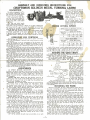
end of the gib which regulates the
tightness of t he tailstock between
the bed ways. These two screws
sho uld be ad iusted evenly so tha t
both en ds of t he gib will bear
against the way wilh the same
amount of pressure.
The tailstock can be set over
lo" for turning tapers. This is
done by simply. adjusting the two
headless screws after loosening the
tailstock cla mp nut.
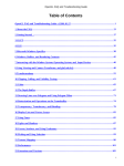
Fig. I
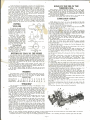
PROPER CUTTING SPEEDS
Spindle Spee d in Revolutions pe r Min.
DIRECT CONE DRIVE
B
The following controls should be tested until the operator i• thoroughly
'140
2
4
1925
2 12 5
3225
BACK GEAR DRIVE
familiar with t hei r use.
Motor Belt
Position
(I) The large handwheel on the front of the carriage propels the carriage
alon51 the bed.
(2) The ball-crank is used for cross-feeding and the two-handle crank
operates the compound rest. Both are graduated in thousands of an inch.
Fig . 3
The compound feed can be turned in a complete circle, by simply loosening
the two Allen set screws, and is graduated in degrees from 0 ° · to 180° so
that any angle can be c ut.
(3 ) The lever on the right front side of the carriage operate• the half.
nut mechanism. When this lever is moved int o the downward position, it e n-
I
1
Spind le Belt Position
2
3
4
- - A- - , -5-4B
I--8-2-~-~2-2 ~,-18_7_
~
187 J'i'7 4'il'!
Much of the success in metal cutting depends upon the choice of
the cutting speeds. Too slow a speed not o nly wastes time, but lea•c•
a rough finish-to o high a speed burns the tool. The chart above
shows the diffe rent speeds available and the set-up for each.
gages the half-nut with the lead screw causing the carriage to travel a long
the bed. CAUTION: Before engaging the half-nut with the lead screw, be
sure that the square head cap screw on the rig ht top side of t he carriage is
loose, otherwise the carriage is locked and serious damage may result to t he
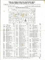
READING THE GEAR CHART
half-nut mechanism.
(4) The lever with the small knob, located at the headstock end of the
lathe, is the reverse gear tumbler lever. This lever is used to reverse o r stop
To simpli fy g ear set·ups U.e th ree different gear bra cke t positions "lavE.
been assigned le tters. These designations will be ·fo und in Figure I on +he
the rotation of the lead screw. Three holes are drilled in the headstock p ro·
viding three positiens for the lever. The cente r hole is neutral and the up-
Threading Chart as position• A, B, and C.
"Back position• • means the position TOWARD the headstock.
per and lower hol es are either forward o r rever se positions, depending upon
th e gear set-up.
position" is the position AWAY FROM the head.tock.
One representative set-up is given in detail below.
(5) The belt tension lever located on the countershaft regulates the
GEAR SET-UP FOR 36 THREADS PER INCH (See
nsion _.c l....ih.!t..J..oi!)!!Le belt~lli'Lth e belt _move the lever backwa_rd,.,·. --...,..
(I) Place 36
ove fo rward t o loosen the- tension-;- therel)y'illlowiiig'Tii'l!5err1o be ?s'slty
on
cha nged to the different pulley steps.
(2) f lace 20
(6) The handwheel on the tailstock operates the tailstock ram. To ad·
11
Front
Figure 3)
tooth gear on
o
tooth gear and
32 tooth g ear on sleeve and
vance th e ram , turn the handwheel in a clockwi se direction.
( 7) The small lever a t the top of the tail•tock is the tailstock
mount in Posit i o~ C
ram clamp
handle. II locks the ram in place when tightened. Note: Before attempting
on gear
bracket with 32 tooth gear in
front
t o move the ram , l oosen the ra m clamp .
that
(I) S PINDLE BEAR IN G ADJUSTMENT:
If any looseness
develops in the spindle bearings it may be removed as fol lows: Loosen
fillist e r head machine screw in left bearing cap one-half t u rn. Then
lig hte n right bearing cap screw until a slight drag is fe lt when the
spindle is rotated by hand. Retighten left bea ring until a ll loose·
ness disappears.
SPINDLE END PLAY: Should e nd play develop, remove it by
tighte ning the collar o n the end of spindle after loosening set screw.
Turn colla r to il snug fit, but not so tight that the spindle turns
hard by hand. Retighten set screw.
CAUTION: Do ,.at confuse spindle end play for loose bearings.
When t urning wood or using speeds over 1250 R.P.M., loosen
the bearing screws be tween Vs a nd V.o~ turn. A tight bearing is
essential for metal turning, b ut not sat isfactory for higher speeds
for wood working. W he n changing back to lower speeds, do not
forget t o t ight e n the bearing cap screws again.
{2) ADJUSTMENTS OF THE CARRI AGE:
If any horizontal
play develo ps between t he carriage and the bed it can be taken
up by screwing t he fou r gib screws up tighter again st the gib. These
•crews should be t ightened just e nough to give a firm •liding fit be tween the carriage and bed.
Bea ring plates on the carriage, which bear on the under side of
both the f ro nt and the back of the bed ways, anchor the ~arriage
firml y to the bed in a vertica l direction. The bea ring plates have
laminate d shims f or adjustmer.i of p "ssible wear.
{3) The gibs o n the c ross feed slid e and the compound feed slide
should be adjusted at regular intervals. The cross feed gib should
always fit snugl y, beca use the cross slide is in almost continual use.
{4) The ba ll and crank handles on the cross fe ed screw and the •
=ompound feed scre w ca n be adjusted fo r play with the t wo nuts on
!he h u bs of the hand les. To ad ju st, tighten the inner nut and lock the
outer nut. An extremely tight fit is likely to result in a je rky feedthe turning force keeps these slides firm against the screw, and play
in the handles does not affect the accu racy of the work. A nice
working , snug fit is idea l.
{5) On the t ailstock, two gib screws a re provi d e d , one on each
position.
32
tooth
Tighten
qear
so
m•shes
with gear in screw Po sition.
Tl·.e 20 tooth gear is a spacer.
ADJUSTMENTS
•
I- -5-50-I--8-20
) - I--12_5_0
Position
-A--·I--::36
:I-:5:-
OPER)\TION AND CONTROLS
,
Spind le B~lt Position
Motor Belt
(3) Place 64 tooth gear a nd
a steel spacer on sleeve and
mount in Posi tion A on gea r
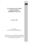
20 TOOTH GEAR-SPACER
Fig. 3-36 threads per inch
bracket with 64 tooth in front
position. Tighten 50 thai ~4
tooth gear meshes with 32
tooth g ea r in Position C.
(4) Swing entire gear bracket upward and tighten so
that the 64 tooth gear meshes
with the 16 tooth spind le
gear.
When setting up the gear tra i n be sure to a llcw sufficient clea rance between two me shi ng gears. Gear clearance d oes not.reduce the accuracy of a
thread cutting operation beca use all the back la•h in the gears is taken up
in one direction.
MOUNTING THE WORK
Whenever practicable, the work is held between centers. There are
two steps in mountin g work between centers: locating the center
poi~ts at each e nd of the work, and countersinking a nd drilling the
ends to accommodate the lathe ce nters.
On round work, centers are us ua lly loc at e d with either the herma·
phrodite caliper or th e ce nte r head aitachme nt for a steel square.
O n the centering of square , hexagon and other regular-sided stock,
lin es are scribed ac ross t he e nds f rom corne r to corn e r. The work is
then center punched at the point of intersection. A little chalk rubbed
over the end of the work before scribing makes the marks easily seen.
After the ends have been countersu nk, the work is mou nted between c e nters. Be sure that the " t ail" o r bent portion of the lathe
dog fits into the face plate slot without resting o n t he bottom of
the face plate slot.
Bring the tailstock up close to the end of the stock and lock in
p lace. Turn the tailstock center into the countersunk hole a nd lock
in such a position th at the play is taken up betwee n ce nters but not
so tight tha t the work will not freely ro tate. PLACE PLENTY OF
WHITE LEAD AT POINT OF BEARING O N TAILSTOCK C ENTER.
Much of the work to be turned or threuded on the lathe is not of a size
-2-
or sha pe wh ich permits mo unting between centers. I n such ca ses it is cus tomary t o m o unt the work o n a face plate or ho ld it in a chuck, a devicr
with jaws wh ich grips the w ork ric;idlv while it is being machineC
·,J
RULES FOR THE USE OF THE
THREADING DIAL
.1 only one chuck is to be purchased, it should be the four- ja w indepentlc nl chuck. The fou r-ja ws are adjusted separately a nd are reversible so that
wo rk of any s.hope can b e clamped from the inside o r the outside.
M o untinq wo rk in t he four-j ~w chuck is largely a matter of cente ri ng.
Determine the portion of the rouqh work that is to run true, then clamp the
work as close ly c entered as possible, using as a guide H·e concentric
on the face of the chuck. les t f or tr ueness, mark ing the high spots
chalk rested a gainst the !col post o r a tool bit mo unted in the
post. The chuck ja ws shou ld be adi usted until the chalk or too l bit
tach the ent ire circumference of tt.e wor k.
rings
wit h
tool
con-
Borin g operati ons require only slig!":tly different tools a nd methods than
thoso fo' external t urning. With t l-. e rou 1.d f:>ol shank porllllel to the lathe
center lin e, set the b ~r inq tool into th e work with the shank bel.,w the cen·
ter line. Then b t putting H:e cuhing edge on exact center line, the correct
amount of bac k ra ke is provided. Tt·.e general rules for the use of the exter nal too ls appl y to b~ring tools. Fo r maximum ri gidity choose the larg est
possible boring tooL Take severa l light cuts rather th a'n a heavy one when
boring .
CUTTING
TOOL BITS
It is wise for th e unskiiiPd worker
to purc hase a Iread 1 formed tools f or
the particular operations he wishes
to perform. Tool bits are not expensive and the purc hase o f a set
of t hese will probably prove the
:heapest and most satisfactory way
:;,ut in th e long run.
~~
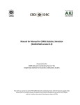
Ceiling Brass or Soft Metal
Fig. 4
ANGLE OF TOOL TO WORK
The a ngl e of the cutting tool to
the work va ries accord ing t o hardness of the metal being cut. The ac:ompanying drawings show in genera l
the p roper angles t o be used for
the differen t classes o f rnetals. Refer
to these d ra wings before taking a cut
until you a r e sure you know th e
proper a ngle for each metal.
C UTTIN G SPEEDS
The speed a cut is taken varies
according to the kind of me tal being
c ut and the kind of cut- whether
roughing o r finishing. Brass may be
cut fa ste r than steel and a light cut
faster than a heavy one.
Cutting Mild Steel o r Cast Iron
Fio. 5
=B-o
Cutting Carbon Steel
Fig . b
SETTING THE TOOL TO THE WORK
Cuts, especially heavy ones, should always be made t owa rd tho headstock.
In tt, is way most of the pressure is t oward the live cent er which revolves
with th e wo rk. Cutting toward the tailstock puts a heavy ad dit ional pr esst re
o n t~ .e tai lstock center and is quite lik e-ly to damage tho center.
The t ype of too l holder, and the wa y it is $_el into t he wo rk, should
a lwa ys be suc h that it tends to swing away from t he work on hea vy cuts.
Whelrc utting at an angle wmrthe compound rest, th·e to ol should be set at
a r ight a ngle to th e surface of the cut, not a t a righ t ang le to the center li ne of the lathe.
Facing c uh represent d iffe rent cu tting relations and t ool angles, and
tools shou ld prefera b ly be special grou nd, for that purpose. Smoother cutti ng and a finer finish can be obtaine d generally b y cutting toward the outside -that is, feeding from t he center of work ou t.
If the too l is ground pr operl y, the p oint of th e t ool will not have
to b e set a b ove or bel ow the c e nte r li ne of the work, b ut should be set on
th e center line.
INDEXING
The spindle p ulley is prov:ded with 60 indexing ho le s which may be en
gaged by means of the knurled pin on the uppe r r ight end of the headstock.
I hese indexinq ho les a re useful fo r such operations as spacing , fl uting,
reedinQ, serra t ing, sproc ket and spoke·spaci ng, et c..
IND EXI NG TABLE
Divisio ns De sired
I
2
3 4
5
b 10 12 IS 20 30 bO
No. of Spaces
bO 30 20 15 12 10
2
I
b
5
4
3
Degrees of A rc 360 180 t 20 90 72 ·60 36 30 24 18 12
6
THREADING*
Only the opera ti on connected with t he cutting of the 60 d eg ree t hread
..,.il l bQ d escribed.
Afte r t he work has been properly prepared for threading, set the comp ound rest at a 29 degree angle so that the tool b it fa ces in the d irection the ca r ria ge will travel. Mount th e t ool bolder in the tool post so
that the point of t he tool is exactly on the lathe center line-tighten the
tool post screw just enough to hold the t ool holder. Then use a center
o r thread gauge to set the t ool point at an exact right ang le to the
work. Tap lightly o n the back of the t ool holder when b ringing into position. With the tool p oint at an exact right a ngle to th e work, rechec k
cen ter linQ position and t ig hten t ool post screw.
Chec k the change gear assembly and the tumbler gear lever so that
the carriage will move in the proper d irection. Adjust belts for a spe ed
of 54 R.P.M.
•
Set the :omp ou nd rest approximately in the center of its ways an d a dva nce t~ e cross fe ed so that it is se t at 0 wi th the tool close to the wo rk.
W it h the p oint of t he f ool about an inch to the right of the start of the
thread , advance the tool with the c om pound red so that th e firs t cut will
b e a bo ut .003 inch.
Sta rt th e la the and engage the hal f- nut lever on the carriage. App ly
plenty of lubrican t to the wo rk. When t he t ool poi nt ha s trave led the
de sired leng th a long the work, raise t he half-nut lever, back out the c ross
feed a turn c r tw~. an d return the carriage by hand to the sta rt ing point.
Advan ce the cre ss feed to its orig ina l position a t 0, advance the compound
rest br the de sired depth of cut, and engage the half -n ut le ver for the
second c ut. All feeding is d o ne with the compound rest. Fol low the same
rout ine on all succeed ing cuts.
When cutting on even-numbere d thread such as 8, 10, 12, 14, etc., \pel
inch). engage the ha lf-nut lever when the stationa ry mark on the threading d ial is in line with any one of two opposing marks on the rota t ing dia l.
W hen cutting any other threa ds (9, II, 13 and 27 per inch) engage the
half-nut le ver when the sta tionary mark on the threading dia l is in line with
the same mark on the r otating d ial.
Precautions: Ne ver disengage the half-nut lever in the mictdle of the
th read without firs t backing o ut the tool with the cross-feed.
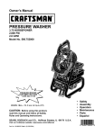
LUBRICATION CHART
See Fig. 7
NO TE: Oilless Bronze Bearings are used in the headstock of this lathe
and lubrication ta kes p lace by oil seepage t hroug h t he p orous bushing wall
thus assuring a filt ered lub ricant.
DO NOT DRILL HOLES TH RU THE BUSH INGS,
Use No. 10 motor oil o r equival ent throug hout unless otherwise specified.
I. Place a few dro ps of oil on the rockershaft bearings and cam every time
1t: e lathe is in use.
2. C ou ntershaft Bearings-Oil every time lathe is used.
3. Moto r Bearings- Sleeve type m ot o rs have tw o oil cu ps which should be
filled once a week with S.A.E . No. 10 moto r oil or equivalent. Ball bearing
motors ha ve a sealed- in type bearing-eve ry six months the small headless
screw in these bearings should be remove d and a moderate quantity of auto·
mo tive cu p grease fo rced around the bearings,
4. left an d Righ t Headstoc k Bea rings-Oil every t ime th e lathe is used,
S. Spind le Pulley-E ve ry time th e la the is use d in back gear, remove the
small screw in th e bottom of th e second step of the idler pulley and oil
freely. Replace screw.
6, Spind le Thrust Bearing-Oi l every time lathe is used,
7. Back Gears and Change Gears-A sma ll a m ou nt of grease, preferably
g raph ite grease, app l;ed to the gear teeth will aid in obtaining smoother,
more q uiet operatio n.
8. Change Gear Bearing s-Put a few drops of oil on the change gea r bearings each time lath e is used.
9. lead Screw Bea ri ngs (left an d r igh t )-Put a few drops of oil in the oil
hol e of th e bearing every time the lathe is used .
10. Carriage Traverse Gear Bracke t- Every time la th e is used put a few
drops o f oil in oil hole on lop of gea r bracket o n back of ca rria ge apron,
II . Ca rriage Ha ndw heel Bearing-Put a few d rops of oil in oil ho le every
time la the is used.
12. Half-nut lever Bearing-Put a few drops of oil in t he oil hole every time
la the is used.
13, Lead Screw- About once a m onth c lea n the lead screw threads with
kerosene and sma ll stiff br ush and a pply a sma ll amou nt of oil.
14. Rack (on bed, under front way)-Abou t once a month app ly a small
amount of cup grease to the rack a fter cleaning with kero sene and a small
stiff brush.
IS.
rl-o-ce- ~
'e"'
c.hUp$ or oil
~etwt ~n
the
hond'Wiu~el
anJ
)C:.rt~W
l,ecring n·hen
ever using lathe .
16. Tailstock Ram-Keep the outside surface of the tailsto ck ram well oiled .
17. l athe Bed Ways-Keep the lathe b ed ways oiled at all times a nd free
from .o~=h i ps. Wipe off the ways before us ing and cover with fresh oil. Always
leave a generous fi lm of oil on th e wa ys when the lathe is not in use. The
lathe should be completely co vered when not in use.
18. Compound Slide Screw-Every t :me la the is used put a few t:hops of oil
between the gradua ted colla!- and bearing plate and on the threads.
19. Cross Slide Screw-Put a few drops of oil in the oil hole above t he
front cross slide screw bearing after removing the small screw. Replac e the
screw. This should be done every time the lathe is used. Clean t he c ross
slid e screw regularly with a sma ll stiff brush. O il the sc rew threads by run ning compound re st b ack and forth ,
20. Cross Slide Ways-Clean regularly and app ly a liberal quantity of oil t..
the ways wheneve r t he lathe is used.
21. Compound Slid e Ways-Clean regula rly and a pply a liberal quantify of
oil to the ways whe neve r the lathe is used.
22. Thr ead Dia l-Once a week put a few drops of o il around the rim of t he
thread dial.
23. Back Gear Spindle- Every tim e tho b ack gears are used, remove the
sma ll sc rew in th e center of the back-gear spindle and o il freely. Repla ce
screw.
24. Bac k Gear Eccentrics (right and left)- Oil occasionall y.
Fig. 7
NOTE: For mo re co mplete informatio n regarding the ope ra t ion of me ta l-c ut li ng lathes re fer to the Sears' Manua l of La the Operat ion listed in our Ca ta log.
A compl e te li ne of a ccessorie s are ava ilable for this lat he. Write f or infc rma t io n.
• Complete info rmation f0r th rea d c uttin g and c oil winding ope ra t ions are contained in the "Thr eadin g Information " b oo klet supp lied with thi s Lathe .
-3-
HOW TO ORDER PARTS FOR CRAFTSMAN METAL
CUTTING BENCH LATHE, MODEL NO. 101.07301
All parts liste d here mu st be ordered thro ugh a ny Se ar s Retai l o r Ma il Order store. When ord e ring, al w a ys give
the following ;
l . Part number in this list.
3. Mode l number l 01 . 0 ~ 301 , an d w hich will be
2. Part name and pri ce in this list.
fou nd on th e plate o n the rear s ide of the bed .
ALL PARTS ARE SHIPPED PREPAID
Po rt No.
l 9-1
l9-150R
l9- 150lA
M6-32B
l 9·2A
l 2-14
l 9- 14
l9-22~
l 9-31 A
M6·32
l 9-42
9-61
l 9-78
M6-79
4;>.88
S10f -91
M6· 100-32
9 · 205
9-210
M6-214
M6-241
M6-243A
M6-249
M6-250
M6-251
M6-252
M6-253
M6-254
M6-255
M6· 256
M6-257
l9- 258
9-729
M6-5
M6-6
M6-7
M6-8
M6·23
M6·30
M6-34
M6-42
M6-44
M6-45
100-60
l2-80
M6-90
M6-129
Selling
Price
Each
Part Nome
BED ASSEMBlY
11
Bed 30
···-········ · ············· -·-- ......$35.35
Bench leg (right) ----·--·-3.BO
Bench leg (left) ----------------·
3.00
Rack Screw (5 reqd.) ea................
. 15
HEADSTOCK AS SEMB LY
Headstock ...................................... $1 1 .35
Spind le Bushing (left) ....... ..
.50
Spindle Bushi ng {right) .......
.45
Heg,dU_oclc Cov er ·~· ..............
2.55
Head Spindle .......................
13. f5
Head Spindle Adju sti ng Coll ar....
.75
Index Pin ..... ............ ..............
.35
Spring
. ...........................................
Spindle Gear Spacer .................•
Spindle Pulley and Back Gear..
Center No. 2 Morse Taper ........
Ball Thrust Bearing . ...................
Spindle Gear ...................
Oiler (2 req.) ea. . .....................
3/ 16" Boll ................................
1 /8" Boll ....................................
Spindle Back G ear-large ........ _
Bock Gear with Bushings ............
Back Gear Bu shing (2 req.) eo.
Back Gear Shaft ..........................
Back G e a r Eccent ric (right) ......
Bode: Geal" Ecce nt ri c (l e ft) . .......
Back Gear Se t Collar ( 2 req . ) eo.
Eccentric Handle ..................
Bock Gear Washer (4 req.) ea...
Back Gear l ock Pin ..................
Bock Gear Plunger Spring ........
Spindle Pulley Bushing ( 2 req.) eo .
Ba ke lite Knob .................
TAILSTOCK ASSEMBLY
Toi lstock ........................
..... .$
Toil stock Base ....... ......................
Tanstock Clomp .................
Ta i lstock Ram ..............................
Hondwheel (wi th handle) ..........
Toilsfock Screw Bearing ..............
Toilstock Rom Screw ....
Tai lstock Rom l ock Ha n dle..........
Tailsfock Rom lock Sleeve (lower)
Tailsto ck Ram lock Sleeve I upper )
Toilstock Base Gib Adju sti ng
Screw ( 2 req.) eac h ..............
Cen ter, No. 1 Morse Toper............
Tailsfock Rom Screw Thrust Nu L ..
Toilstock G ib ............................
.15
.65
3.65
2.40
2.10
.65
. 20
.15
.1 5
3.65
3.00
.35
.65
.40
.35
.55
.80
.15
.55
.15
. 35
. 25
6.50
3.85
.45
5.15
2.00
1.15
1.00
Selling
Price
Part Name
Each
Carriage Bearing Plate (front) ___
.85
.85
Cordage Ba a ring Plate (real") ..
Carriage Gllib ................................
.75
Boll Crank, with Handle................ .. 1.15
Spring ... .. ...................................... .
.15
. 35
Threading Dial ........................... .
Threading [lial Body ................. .
.60
Thre ading Dial Pinion ................
.85
.15
Threading Dial Shaft ..................
Corrioge Hand wh eel Shaft
and Pinion ................................ 1.55
M0.6s - - Carr iage fro verse Pinion - and Shaft .................................. 1.25
M6 -74
Ca rriage Screw Thrus t Was her..
.1 5
Carriage Traverse Rock ............... 2.65
L9-86
M6-93
Handwheel Washer ......................
.15
M6· 102
Carriage Trave rse Gear ··----~----· 1.00
M6-1 03
Ball Crank Handle ......................
.40
Th reading Dia l Washer ........... ..
.15
M6-155
M6-159
Carriage Shim (rear) ............... .
.25
Carriage Shi m (front) ............... .
. 25
M6-160
Corrioge lock Screw (2 req.) ea.
.55
M6-177
.15
9-210
3/16" Ba ll ....................................
Cross feed Bal l Crank Nut........ ..
.40
M6- 262
Pa rt No.
M6-54
M6 -55
M6-57
M6 -61
9-61
M6-62
M6-63
M6-64A
M6-65
M6-67
M6·37
M6-48
M6-56
M6-104
10- 226
M6-263
M6-301
M6·302
M6·303
M6-304
M6-305
M6-306
M6·307
M6·308
M6-309
.65
M6-311
.20
.20
W44-2
.25
1.95
.20
.65
CARRIAGE AND RACK A SSEMBLY
Carriage ................. .. ... ..............$16.65
M6·9
M6·11
Carriage Tra verse Gear Be ar ing
.55
Split N ul (1 pr.) ........................
.B5
M6·12A
Split
Nut
Guide
...........
.40
M6-13A
M6- 14
Caaiogo Clamp ............................
.55
M6-17
Carriage Graduated Collar ........ 1 .05
M6-19A
Carriage Slide Nut............................ 1.15
Hand Whee l (with handle) ________ 2.00
M6-23
Split Nut l evei ............................ .65
M6· 29
Carriage Slide Screw
M6·36A
( l lluL as M6-36) ............ .
1.80
Spl it Nut Com ...............
M6-38
.40
Ca rriage Slide Screw Bearing .... 1.25
M6-46
COMPOUND REST ASSE MBLY
Carriage f eed Screw Guard ----- ~
Grotluoted Colla r ........................
Cross Fee d Gib ............................
Bo ll Crank Handle ( 2 req . ) eo .
Gib Screw Nut (3 req .) eo ..... _
Co mpound Bal l Cra nk Nut
Compound Rest Swive l (lower) ..
Compou n d Rest Swivel (upper) ..
Componnijl Rest Tool Post Slide..
Compound Rest Tool Post
Sl ide Gib ..................................
Compound Rest Feed Screw ........
Tool Post Slide Nut ....................
Compound Rest fe~d Screw
Thrust Plate ..............................
Compound Rest Boll Cronk
(with handl e s) ........................
Compound lock Plunge r .
(2 req.) each ......................
Com pound Rest Feed Screw
Thrust Collar ............................
Allen Wrench 1/ 4 " ....................
. 85
1.05
.55
.40
.15
.40
9.00
4.35
5.15
.55
.75
.85
.45
1.00
• 20
.40
.15
LEAD SCREW A ND fEED GEAR ASSEMBLY
l ead Screw Bearing (right) ......$ .B5
M6-16
.so
Reve rse Tumbler Plunger ........... .
LJ - 23
Ch
a nge Gea r Brocket .................. 2.85
M6- 25
Screw Beoring (l e ft ) .................. 1 .45
M6- 27
Tumbler G ear Bushin g
M6-33
(2 req . ) each ........................ ..
.20
lead Screw ..... .............. ............... 3 .80
l 9-35
Rev erse Tumbler Knob ................
.50
S8-45
Spindle Ge ar Stud .................... - 1.45
M6· 47
l ead Screw G ear Spacer ........... .
.40
M6-50
Reverse Ge ar Tumbl e r ................ 2.35
M6-58
Reverse Tumbler Gear- 20 teeth
M6-59
.55
.-'1.5
Reverse Tumbler Gear - 24 teeth
M6-60
.15
Plunger Spring ............................
S8-63
M6-70
Compound Gear Bushing
(2 req . ) each ......................... .
.25
Change Gear Stud Sleeve
M6-73
{ 2 req.) each ..........................
.75
Selling
Price
Part Name
[ach
Char:ge Gear Brocket Nut ..........
.35
Change G ear Wash e r
(2 req. ) each ..........................
. 15
M6·101-16 Compoun d Tumbler G ear
(1 6 and 32 teeth) ................. . 1.35
M6-114
.80
l ea d Screw Co llar (left) ......... ..
M6-165
Gear Spacer (3 re(l. ) ea ............
.4 5
Wre nch . ....... ................................. .
M6· 312
.85
l ead Screw Collar (right}
.40
l 2-682
Pa rt No .
M6-88
M6· 93
CHANGE GEA R ASSEMBLY
M6·99A
M6- 101-20
M6- 101 - 24
M6- 101 - 32
h\6-101-36
M6·101 -40
M6·1 01-44
M6-161 -46
M6- 101 -48
M6-10 1- 52
M6-101 - 54
M6- 101-56
M6-1 0 1-64
Threading Chart ...........................$ .65
Change Gear (20 teeth) ...........
. 55
Change Gear (24 teeth) .......-------.55
Cho nge Gear (32 teeth}
.65
(2 req . ) eoch ........................
Change Gear- 36 Teeth
.65
.65
Change Geor---40 teeth
.80
Change Gear---44 teeth
Change Gear-46 teet h
.85
Change Geor-48 teeth
.B5
Change Gear-52 tee th
. 95
Change Gear-54 teeth
.95
Change Gear-56 teeth
.95
Change Gear I 64 teelh)
(2 req.) each .......................... 1.00
CHANGe GE AR GUARD A SSEMBLY
M6- 28
M6- 92
M6· 95
M6-96
M6-157
9-729
Chonge Gear Guard ....................$ 5.65
Change Gear Guard Hing e Pin ....
.15
Change Gear Guard Bracket ...... 1.55
Change Gear Guard Bracket Plate
.65
latch Spring ..................................
.2u
Knob .............................................
.25
L9- 20A
M6-21
51 -52
51 - 56
M6-76
M6-77
M6-80
M6-107
M6- 109
9- 122
M6-427
l2- 682
Cou ntershoft Bracket ................... $
Cou ntershoft Hong~r ............. .
Rockershoft Ha n dle ......................
Rockershoft Handle Ball ............. .
Rockersh oft ..................................
Rockershoft Hub ........................ ..
Counfershaft Pulley (4 stop) .... ..
M6-39
M6-40
9-41
M6-136
M6-148
Tool
Tool
Tool
Tool
Tool
M6-115
l9- 125
l 9- 127A
9-144-1
l 9· 365A
9-385A
M6- 423
MISCELLAN EOUS
Combination Wrench .................... $
Motor Belt .................................. ..
Con& Belt ..................................... .
lathe Dog I 1" cap.) ..............
face Plate ( 5· 1/ 4" ) ..................
Too l Bit ....................................... .
Motor Pulley .......................... ..
COUNTERSHAFT ASSEMBLY
~~~~::~:~~!! Bs:~;i~~es (·2·~;-~-_-j--~~:
Hanger Hinge Pin ....................... .
Coun tershaft Pulley (2 step) ..... .
Collar I 2 req.) each ................
.4:>
1.85
1.05
2.35
.85
.25
.35
1. 85
.40
TOOL PO ST A SSEMBLY
All P; ices Are Sub ject to Cha nge W itho u t No tice
NOTICE: This is NOT a pocking slip. The parts shown and li sted include the acc essories that ore not necessarily po rt of this tool .
NOTE : Sta ndard ports , such a s bolts, nuts , washers, etc. , ore not lis ted above a s s uch ports con be obtained loca ll y.
- 4.
4.40
4.00
.65
Post ......................................$ 2.45
Post Wa s her ........................
.45
Post Rocker . ........................
.60
Post Anchor . .........................
.80
Post Se t Screw ....................
.60
.
.85
1.25
1. 85
1.45
3.B5
1.20
1.45