
1
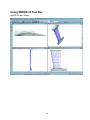
WINGS 32
Professional User Manual
Copyright 2003 (c) Vacanti Yacht Design LLC
All Rights Reserved
1
WINGS 32 Contents
Notice to Non United States Users – Numerical Errors ............................................................. 5
TECHNICAL SUPPORT .................................................................................................................. 5
TECHNICAL SUPPORT .................................................................................................................. 6
REPORTING A BUG / ERROR ................................................................................................. 6
TECHNICAL SUPPORT LIMITATIONS:......................................................................................... 6
We cannot provide “online Teaching”........................................................................................ 7
FREE SOFTWARE UPDATES:....................................................................................................... 7
Just Starting Out ............................................................................................................................ 8
WINGS 32 System Requirements ............................................................................................... 10
European Users - SPECIAL NOTE: WINGS 32 Will Not Start Errors..................................... 10
Using WINGS 32 on More than One Computer ......................................................................... 12
QUICK START............................................................................................................................... 12
To begin new design in WINGS 32, select FILE, NEW… ....................................................... 12
Using WINGS 32 Tool Bar ........................................................................................................... 14
Open A File ....................................................................................................................... 14
Save This File ................................................................................................................... 14
Print .................................................................................................................................. 14
Printer Setup..................................................................................................................... 14
Calculate Hydrostatics..................................................................................................... 15
Change Lines Drawing..................................................................................................... 15
Vertex Net ON or Off........................................................................................................ 15
UNDO ............................................................................................................................... 15
Render Keel or rudder................................................................................................... 15
Zoom In............................................................................................................................ 15
Zoom Out .......................................................................................................................... 15
View Buttons.................................................................................................... 16
Animate ............................................................................................................................ 16
X and Y Coordinates .............................................................................................. 16
2
Foil Design List.............................................................................. 16
About ................................................................................................................................ 17
Information – Help............................................................................................................ 17
Begin A New Design .................................................................................................................... 19
Editing the Design........................................................................................................................ 20
Keel or Rudder Design Principals............................................................................................ 20
PLANFORM CHANGES: .................................................................................................. 20
THICKNESS CHANGES................................................................................................... 20
SHARP BREAKS .............................................................................................................. 20
BULB TRAILING EDGE SHAPES .................................................................................... 21
Changing Foils on a Keel or Rudder ....................................................................................... 21
Editing Tool Buttons ................................................................................................................ 21
Edit FOIL Dimensions Numerically. .................................................................................. 21
TOOL Menu ................................................................................................................................... 22
STRETCH / SHRINK Keel or Rudder...................................................................................... 22
SHIFT Keel / Rudder ............................................................................................................... 23
Keel Parameter and Ballast Editor ............................................................................................. 24
Saving All Changes or Cancel any changes..................................................................... 24
Leaving The Parameter Editor .......................................................................................... 24
WINGS 32 Foil Chord Numbering System ................................................................................. 25
Adding Foil Chords .................................................................................................................. 25
Positioning With Mouse ........................................................................................................... 25
Insert by Foil Index .................................................................................................................. 25
Deleting Foil Chords .................................................................................................................... 25
Select With Mouse................................................................................................................... 26
To Delete a Foil Chord: ........................................................................................................... 26
Delete By FOIL Number.................................................................................................... 26
To Delete a Foil Chord: ..................................................................................................... 26
Changing Spline Tension ............................................................................................................ 27
MAXIMUM POSSIBLE SPLINE TENSION ............................................................................. 27
Fairing the Keel or Rudder .......................................................................................................... 27
WINGS 32 Design Tools .............................................................................................................. 28
IMPORTING EXISTING CAD FILES............................................................................................. 29
Importing DXF Reference Files ............................................................................................... 30
REFERENCE and VERTEX Data ........................................................................................... 30
REFERENCE DRAWING DATA ............................................................................................. 30
VERTEX Data File ................................................................................................................... 31
Removing A Reference File..................................................................................................... 31
Calculations.................................................................................................................................. 32
Hydrostatics Calculations ........................................................................................................ 32
3
LIFT and Drag Calculations......................................................................................................... 33
LIFT CURVE SLOPE Calculation ................................................................................................ 33
Keel Thickness Vs Span.............................................................................................................. 34
Keel Chord Length Vs Span........................................................................................................ 35
Exporting DXF CAD Files ........................................................................................................ 36
Exporting DXF CAD Files ........................................................................................................ 37
Skin Thickness Deduction in CAD Files .................................................................................. 38
Tips for Viewing and Exporting Keel or rudder Designs.......................................................... 39
CADKEY Files ......................................................................................................................... 40
Computer Numerically Controlled Machining .......................................................................... 41
Special Stations, Waterlines & Buttocks ................................................................................... 42
Rendering WINGS 32 Keel or rudder Designs .......................................................................... 44
Importing Keel and Rudder Files................................................................................................ 46
Importing Keel and Rudder Files................................................................................................ 47
File Data Definition .................................................................................................................. 47
DXF FILE Entity Types ............................................................................................................ 47
How To Import Keel And Rudder Files .................................................................................... 47
Adding Multiple Keel / Rudder Elements................................................................................. 48
Printing.......................................................................................................................................... 48
Printing Views of Your Design ................................................................................................. 48
Printing Views of Your Design ................................................................................................. 49
Printing Keel or rudder Offsets ................................................................................................ 49
4
Notice to Non United States Users – Numerical Errors
“WINGS 32” requires that the regional setting for a DECIMAL POINT be set to a PERIOD (.) and not a COMMA
(,) Setting the decimal point definition to a COMMA causes WINGS to read data files incorrectly. For example
the number 1234,567 is read as 1234 and 567 as integers not 1234 POINT 567. Therefore WINGS requires
1234.567.
To make the correction click Start, Settings, Control Panel, ( Date,Time, Language and Regional Options)
choose Change the Format of Numbers and under NUMBER type 123,456,789.00 with a PERIOD before the
last two zeros. No need to change Currency.
Technical Support
Technical Support Limitations
Free Software Updates
5
TECHNICAL SUPPORT
Before you contact Vacanti Yacht Design for Technical Support you MUST first:
1) READ THE USER MANUAL
2) Verify that your computer is free of Viruses
3) CHECK our Home Page on the INTERNET for a Revised Version of WINGS 32 The
address is http://www.vacantisw.com
3) Verify that you know the exact steps that lead to the problem.
4 You MUST first REGISTER your copy by sending us:
A) Your name and address
B) A 24-Hour FAX Number - we will not make attempts to call at
specific hours of the day OR E-MAIL Address. E-MAIL is MUCH PREFERED.
5) All Users must provide at least ONE of the following:
A) 24 Hour FAX number. The fax must be available AT ALL TIMES. We
cannot call WORLDWIDE from the WEST COAST of the USA to accommodate
your schedule. We will try to reply to your fax ONCE. If it is not operational, we
will not retry. Include your FAX number on your FAX to us! Our Fax
Number: 425 413 2815
B) E-MAIL Address: This is the BEST possible solution. Using e- mail we can
respond at anytime, we can accept WINGS 32 design files that you create as
attachments to you letters. We can return these files to you with
recommendations and file corrections. Contact Vacanti Software at
[email protected]
REPORTING A BUG / ERROR
PLEASE - Verify that the error can be repeated. Clearly and in as much detail as possible
describe what steps were followed and how the error occurred. Include your 24-Hour Fax
number, your E-mail address or your 24 Hour Phone Number ON ALL
CORRESPONDANCE.
TECHNICAL SUPPORT LIMITATIONS:
Vacanti Software currently provides Free Technical Support. This free support is only
possible if we are allowed to reply to you at our convenience. Because we provide this
support worldwide, your call or fax or e-mail to us may arrive at any hour of the day or night.
Therefore it may not be possible for us to reply to you on a schedule you supply.
6
If your FAX or phone is not operational 24 HOURS a day, it may be very difficult for us to
reply. Please try to consider contacting us via email if at all possible so that we may provide
detailed information as rapidly as possible.
We cannot provide “online Teaching”
Unfortunately, our low prices do not allow us to provide the ability to call you and coach you
in the use of WINGS 32. If you are a new computer owner, we suggest that you read our
manual and make an effort to carefully work through a design yourself. New computer users
should expect to spend several hours getting used to the conventions of Windows, Computer
Aided Drawing (CAD) programs and other information.
We are constantly adding information to our user manual and updates of on-line help will be
made as often as possible. Please check our INTERNET HOME PAGE www.vacantisw.com
for updates or check new updates.
“WINGS 32” has been in use around the world for several years. It has been used to create
everything from simple rudders to bulbed keels for major racing yachts. WINGS 32 is based
on the HULL design program PROLINES. Therefore WINGS will be familiar in operation to
those who use PROLINES.
FREE SOFTWARE UPDATES:
Free software updates are available on-line at our web site or you can request a copy of our
latest WINGS 32 release by mail, phone, fax or e-mail.
1) Download new software at: http://www.vacantisw.com
2) e-mail a request for updates to: [email protected]
3) Fax a request for updates to: 425 413 2815 (Dial International long distance for the
USA)
7
Just Starting Out
Introduction to WINGS 32
Register WINGS 32
8
Introduction to WINGS 32
WINGS was first created as a DOS based program several years ago. It has been completely replaced by a
new version that has full 3D NURB Surface capability based on PROLINES 7 Code. Therefore operation of
WINGS 32 is very similar to PROLINES for editing functions, calculations etc.
“WINGS 32” represents a major change in the numerical structure of the original DOS version of WINGS. This
new version has a completely new “NURB Engine” that is used to compute true Non-Uniform Rational B-Splines
(NURBS) surface. This new engine is faster and more efficient but is not compatible with the old DOS version of
WINGS. The old DOS version used a very simple set of 2D offsets and a simple spline to define the outer shape
of the keel or rudder. Another spline defined thickness. In this new version the Keel or Rudder is defined as a
vertical collection of foil shapes and is a true 3D structure from the beginning. As a result any design in WINGS
32 can be output as an IGS NURB file that is compatible with Computer Numerically Controlled Machining
(CNC) and Structural Finite Element Analysis (FEA). “WINGS 32” also provides normal 3D DXF and 2D DXF
files for other applications. WINGS 32 can also print basic views of any keel and rudder design.
WINGS 32 uses foil shapes that we created in our program FOIL. These shapes are not the standard table of
offsets from the NACA or other databases – they are NURB offsets that create a spline that passes through the
NACA or other database values. That permits WINGS 32 to be a full 3D NURB surface. We have provided the
most common foils used worldwide with WINGS 32, but should a designer require access to a new foil that is
not found in WINGS 32 values the new shape can either be created in FOIL (purchase of the program is
required) or we can create the foil at no cost in foil and provide that to the designer. We will provide reasonable
support but if a number of new foils is required we suggest the design office to purchase FOIL as well.
“WINGS 32” was created specifically to be easy to use. Therefore one of its most important features is the ability
to use Parametric Keel and Rudder Design. Parametric design simply means that the user creates an object by
specifying the object type (Bulbed Keel or Straight), and the dimensions of that object such as its span overall,
root and tip chord lengths. The designer is not required to build each shape "stick by stick" as is the case in
many CAD programs.
When creating a keel or rudder design, the design must not only be fair, it must also meet the design objectives
for ballast amount, center of gravity, wetted surface and a host of other factors. Therefore, WINGS 32
hydrostatics, lift and drag computations are built in. These features can be accessed at any time during the
design process.
We encourage you to open one of the sample designs provided with WINGS 32 (File, OPEN.. Select a file name
that ends in .w32) and then to explore the program by looking at each of menu lists. Take some time to look at
each menu and try to get an idea of the functions WINGS 32 provides. With this simple knowledge, attempt to
modify the keel or rudder. Try Calculate Hydrostatics in the CALC menu. During this exploration take note that
WINGS 32 provides pop up help just as the mouse is moved around the screen. Position the mouse over an
icon or speed button and within 2 seconds a button name will appear in yellow at the cursor. At the same time,
in the lower left corner of the screen, a single line of text explains how to use the button.
Have Fun Exploring!
9
WINGS 32 System Requirements
“WINGS 32” is a full 32 bit program designed to operate under Windows XP or later. It
requires at least 16 Megabytes of memory, 10 MB of free hard disk space, a mouse or other
Windows pointing device, a graphics card capable of at least 16 bits per pixel color. WINGS
32 must be used on a display of at least 800X600 pixels but at least 1024 x 768 pixels will
yield far better performance. Best performance in rendering keel or rudder shapes in WINGS
32 will result with graphics cards that provide full 24 bits of color per pixel (millions of colors).
European Users - SPECIAL NOTE: WINGS 32 Will Not Start Errors
WINGS 32 requires that the regional setting for a DECIMAL POINT be set to a PERIOD (.)
and not a COMMA (,). Setting the decimal point definition to a COMMA causes WINGS 32 to
read data files incorrectly. For example the number 1234,567 is read as 1234 and 567 as
integers not 1234 POINT 567. Therefore WINGS 32 requires 1234.567. To make the
correction click Start, Settings, Control Panel, (Date, Time, Language and Regional Options)
choose Change the Format of Numbers and under NUMBER type 123,456,789.00 with a
PERIOD before the last two zeros. No need to change Currency.
WINGS 32 makes use of the OpenGL professional rendering software provided on all new
computers. Therefore more rapid graphics performance is made possible when using 3D
graphics accelerators that support OpenGL. Older computers will require substantial time to
render the keel or rudders to high definition without a 3D accelerated graphics card.
10
Register WINGS 32
PRINTER MUST BE TURNED ON.
“WINGS 32” is protected from pirating by Software Copy Protection. Each copy of WINGS 32
will be ”locked” to the computer it is run on. When WINGS 32 is installed and run for the first
time the message window shown below will be displayed after a series of simple error
messages. Please accept each notice and proceed to the registration dialog. There are two
buttons on the bottom of this form – one labeled “Close Dialog and Contact Vacanti Yacht
Design”, the other button labeled “Unlock WINGS 32” is used after you have received a
computer Key Word from Vacanti Yacht Design.
Send this number
to Vacanti Yacht
Design
Vacanti Yacht Design
will send this number
back to you.
FAX to 425 413 2815
Press the “Close Dialog…” button the first time you run WINGS 32. A special registration
form will be printed that contains a computer number that is unique to your computer. WINGS
32 will then close. Send this number along with your name and address to Vacanti Yacht
Design by e-mail or fax using the information printed on the form or on the dialog box.
Vacanti Yacht Design will send back to you a computer “Key Number”. Run WINGS 32 again
and enter this key number in the space provided for it on the Registration Dialog. Then press
Unlock WINGS 32. SAVE the Key Number in a safe place.
The key number will be saved in a WINGS 32.ini file that must not be disturbed. If the file is
erased or corrupted, the registration form will be displayed and you may re-enter the key
number.
UPGRADING COMPUTER HARDWARE
If the computer hardware that is used to run WINGS 32 is substantially changed it may fail to
run and present the registration form. Should this happen, please contact Vacanti Yacht
Design and describe the upgrades that have been made. If you purchase a new computer
please completely install WINGS 32 on the new PC and remove it from the old computer.
Then follow the registration procedure described above.
11
Using WINGS 32 on More than One Computer
If you wish to use WINGS 32 on more than one computer at different times, you must contact
Vacanti Yacht Design LLC. Special arrangements may be made for a second key number.
If you wish to operate WINGS 32 on two computers at the same time, for example a design
office with more than one designer, a second copy of WINGS 32 may be purchased at a
discount.
QUICK START
Keel and Rudder Design Process in WINGS 32
To begin new design in WINGS 32, select FILE, NEW…
1) Choose Meter / Kg or Inch / Pound dimensions
2) Enter the dimensions of the Keel or Rudder in the New Design Dialog
3) Choose the tip type by clicking on the Radio Button near the desired type
4) Choose to add a bulb or flange (top mounting) to a keel
5) Click OK to see the new keel or rudder designed
6) Click OK on the Display Mode Dialog Box
7) The new design will be displayed in all four views
The keel or rudder displayed typically has 4 foil chords displayed. They are shown as a
vertex box (small open square) on the leading edge and the trailing edge. All editing in
WINGS 32 is accomplished by dragging or numerically editing the leading or trailing edge
vertex controls for each foil defined on the keel or rudder. Change the overall dimensions of
the keel or rudder by selecting EDIT, Parameter Design Editor.
Choose CALC, Hydrostatics to view the weight, frontal area and many more characteristics.
Choose CALC, Lift & Drag to see the projected LIFT (Side Force) and Drag (Slows the boat
down) forces for the keel or rudder, not including the effects of the Bulb.
To make detailed changes to the planform add foil shapes to the span of the keel or rudder
by selecting EDIT, ADD FOIL, With Mouse or By Index. Placing two foils very near each other
along the span creates a local sharp break in the planform.
Move the foils by dragging them with the LEFT mouse button or numerically by RIGHT clicking on a vertex. A
dialog box showing all data for the selected foil pops up and all data can be edited in order to insure a design
meets exact criteria.
12
Using WINGS 32 Tool Bar
WINGS 32 Main Screen
13
Using WINGS 32 Tool Bar
The tool bar shown above gives the designer access to the most often used functions within
WINGS 32. The basic name of each function is available by simply resting the mouse cursor
over one of the buttons and after a few seconds a small yellow help balloon will appear with
the button name written inside. Additional information about each button is also available in a
short sentence written in the status line at the bottom of the screen.
More extensive descriptions of each button are presented below. Each button is described in
order from left or right. For example the first button is the open folder, used to open an
existing file.
Open A File
Clicking this button will bring up a standard Windows dialog box with all WINGS 32 designs
found in the current directory. This button cannot be used to read CAD files or other file
formats. It is only used to open an existing WINGS 32 design file (extension .w32).
Save This File
The floppy disk image on this button indicates that the current WINGS 32 design that is on
screen will be saved. Other files such as reference files or CAD files are not saved with this
button.
Print
Select this function to print one or all of the 4 views shown on screen. A dialog box will
appear that allows the selection of one or all of the views and the maximum scale that the
drawing can be created. The scale is a fraction computed as: Paper Inches / Keel Size
Inches or Paper mm / keel mm. Therefore if the maximum paper dimension is 11 inches
vertically and the maximum keel span is 44 inches, the greatest possible scale is 11/44 =
0.25. Changing the direction of the paper to match the greatest paper dimension to the
greatest keel or rudder dimension will produce a drawing of the greatest possible scale. The
greatest possible scale is the closest possible to a scale of 1 or full size.
Printer Setup
Select this button to choose a printer that is installed in Windows, print quality, paper size,
paper orientation (portrait or landscape) and other printer functions. Be sure that the correct
printer driver is installed in Windows before attempting to print.
14
Calculate Hydrostatics
The hand held calculator symbol on this button indicates that clicking the button will cause
WINGS 32 to compute a complete set of Hydrostatics information, such as displacement,
centers of gravity and various shape coefficients.
Change Lines Drawing
The crossed lines on this button image correspond to the stations, waterline and buttocks
traditionally found in drawings. Selecting this button allows the designer to turn various lines
on or off and toggle between showing NURB splines and traditional stations etc.
Vertex Net ON or Off
Clicking on this button causes the program to either display or hide the vertex control points
that define the keel or rudder shape. The vertex markers must be turned on to use any of the
mouse editing tools. The vertex markers are the small square boxes located at the end of
each foil chord.
UNDO
The circular arrow symbol will become active after you have changed anything that alters the
design from its initial state. You may sequentially UNDO up to 90 steps.
Render Keel or rudder
This button is seen as a rendered image. Click this button to open the OpenGL rendering
dialog.
Zoom In
The magnifying glass with a plus (+) sign indicates that you can enlarge a desired section of
a view. Click on the button and the cursor will become an UP Arrow symbol. Move the cursor
to the upper left of the area you wish to enlarge. Click and hold the left mouse button down.
As you drag the mouse a zoom window box will be drawn. Release the mouse button when
the area you wish to enlarge is enclosed within the zoom window box.
Zoom Out
The magnifying glass with a (-) sign indicates that the active view will be returned to normal
view. Therefore, to cause a zoomed view to be returned to its normal size, first select the
15
desired view by clicking the left mouse button in the title bar. When the desired view title bar
is highlighted, click on the Zoom Out button.
If for any reason the views are not drawn properly, select View – Fit All Views to Windows.
View Buttons
The view buttons cause the view given by the title of the button to be drawn. For example, the
button labeled BODY will cause the Body View to be drawn.
Animate
The Animate button allows the designer to see a “movie” of the keel or rudder played for him
in the perspective window. WINGS 32 will display a dialog that
asks how long to delay before drawing the next view. The
animation sequence will show several views from above and
below the keel or rudder. The animation control dialog will
remain open so that you may stop, restart or change the speed
of the animation.
X and Y Coordinates
These are display windows that cannot be edited. They indicate the current position of the
mouse in inches or millimeters depending on which units are being used in the drawing.
Foil Design List
This is a pull down list of all of the foils used to design the keel or rudder. Click on the right
pull down arrow and display the complete list of foils. The top most foil in the list is the root
chord and the bottom most foil is the tip chord. Click on any foil in the pull down list to show
all of the data related to that foil. You may type new dimensions for the foil or change the foil
type by selecting a new one from a list.
16
About
The button displays WINGS 32 Copyright and Version information.
Information – Help
“WINGS 32” provides extensive on-line Help. Clicking this button will provide information on
how to use WINGS 32. A great deal of the information that is found in this manual is available
on-line. (OnlIne Help is under development as of this writing – but will provide a copy of this
manual)
17
Design
Beginning a New Design
Parametric Keel or Rudder Design
Editing a Design
Adding New Foil Shapes
Deleting Foil Shapes
Changing Spline Tension
Fairing the Keel or rudder
18
Begin A New Design
“WINGS 32” allows a designer to create a new design with Parametric Keel or rudder Design methods.
Parametric Keel or rudder Design creates a new keel or rudder by asking for just the basic keel
or rudder parameters such as span, draft, sweep angle, and foil types. WINGS 32 uses the dimensions to create
a keel or rudder shape that is already fair or very nearly fair. The designer should then modify the keel or rudder
to suit his specific design task by moving vertex points and adding, subtracting foil shapes or vertex points.
To create a new
design using
parametric data,
select FILE,
NEW..., . Now
select the keel or
rudder type that is
the closest to the
type you wish to
design. Be sure to
specify the
measurement units
that will be used to
specify your
design. If units of
meters are
chosen, WINGS
32 will convert that
data into
millimeters after it
creates the design
on screen. If Units
of FEET are
chosen, the data
will be converted
to INCHES after
the keel or rudder
has been created.
Change the
dimensions of the
keel or rudder
according to the
planned design.
Carefully check to
see that all of the
choices and
dimensions have
been properly
selected and click OK. The keel or rudder will be drawn in all views. Modify the default keel or rudder shape to
meet your design needs. Use the editing tools found in the EDIT, SPLINE and TOOLS menus.
Import 3D DXF Files to create a keel or rudder shape within WINGS 32 based on data that has been
digitized or created in a 3D CAD program such as AutoCAD, CADKEY, DesignCAD 3D or others. “WINGS 32”
is expecting elements in the DXF file that are LINES or POLYLINES, not Splines or ARCS or other elements.
The data must be 3D and contain Beam, Height and Length. The axes in WINGS 32 are defined as follows:
X=BEAM, Y=Length Along The Keel or rudder, and Z=Height above or below Root Chord or other reference
line.
19
The data in a 3D DXF file may be read as offsets for vertex control points to create a keel or rudder directly from
the DXF file IF the file meets the following criteria:
1) The data is station oriented no waterlines or other data.
2) The number of line elements or the number of vertex points per polyline is the same on each station and
there are less than 30 points per station or vertex column.
3) The number of "stations" is 30 or less.
If the file does not meet these criteria, then it can be read in as a simple drawing and displayed for reference on
the screen. This makes it possible to modify a keel or rudder created by WINGS 32 Parametric Keel or rudder
Design so that it overlays the reference keel or rudder by using WINGS 32 editing tools.
Editing the Design
Keel or Rudder Design Principals
PLANFORM CHANGES:
“WINGS 32” was developed around the concept of applying fixed foil shapes at specific
locations vertically along the keel or rudder. In order to preserve the specific foil shape
chosen by the designer, only the first leading edge and last trailing edge vertex control points
of each foil is displayed. The rest are hidden from view and protected from being changed
during the editing process. The planform shape of the keel or rudder is then adjusted by
moving the leading or trailing edges fore and aft and vertically.
THICKNESS CHANGES
In the FRONT view of a keel or rudder only the THICKNESS CONTROL vertex for each foil is
displayed. This is typically the maximum thickness of the chosen foil. Moving this vertex in
the FRONT view moved the foil vertically or changes its thickness. This function can
therefore be used to define the shape of a bulb at the bottom of the keel or the shape of a
flange at the top or any other detailed thickness feature of the keel or rudder.
SHARP BREAKS
It is frequently very important to provide a very sharp change in thickness, such as the
transition from the top of a bulb to a main keel strut. To make the changes abrupt or sharp,
locate TWO or THREE foils of the same type vertically very close to one another. This will
cause a very tight radius or sharp bend to develop at the combined foil locations. To insert an
extra foil where a tight bend is desired, select the EDIT menu, choose INSERT a New Foil…
by Mouse Click or index. If the design has many foils (up to 50 are permitted) it may be easier
to choose the index method. Before making this choice use the OPTIONS menu to LABEL
FOIL CHORDS, then choose the correct index location based on those numbers.
It is also very important to recall that the FRONT view can be used to adjust rapid changes in
thickness once a collection of 2 or 3 foils have been located together. The thickness of each
foil can now be adjusted to provide the needed bulb shape.
20
BULB TRAILING EDGE SHAPES
The trailing edge shape of a bulb designed with a normal NACA or other standard foil shape
will result in a vertical bulb tail that is “fish like”. To make the trailing edge into a flat or square
“Beaver tail” shape or any other shape requires using foils that have the desired shape at the
trailing edge. Recently we have added a SQUARE TAIL shape that may be used on the bulb
to achieve the proven low drag qualities of a bulb with a tail that is horizontally flat or nearly
flat. The designer is therefore encouraged to use the new SQUARE-tail shape we have
provided in combination with other foils or design another shape in our program FOIL to
achieve the desired trailing edge.
Changing Foils on a Keel or Rudder
All of the foils used on any keel or rudder can be listed by clicking the
pull down menu of foils located at the right side of the main tool bar. The foils are listed as
they appear in order from top to bottom. For example the foil listed at the top of the list is the
foil at the top or root chord of the keel or rudder. The foil shown at the bottom of the list
corresponds to the tip chord furthest away from the keel or rudder. Change any of these foils
by opening the list and click on a foil name. The Chord Editor Dialog (see below) will open.
Click on the Chord Foil file name to choose a new foil shape. Click OK on the Chord Editor
Dialog to see the new foil drawn within the keel or rudder. The new foil will be listed in the pull
down menu.
Editing Tool Buttons
“WINGS 32” offers several means to alter the shape of a Keel or Rudder. They include editing with the mouse or
changing vertex control points numerically with a spreadsheet or keyboard. If you are working towards a design
that has very specific dimensions required at a specific location on the keel or rudder, it may be most efficient to
adjust the design numerically.
Edit FOIL Dimensions Numerically.
Right click on a single vertex in any planar view (Body,
Plan, and Profile) and bring up a dialog box that
contains the 3D dimensions of that vertex point.
Move A vertex Point with the mouse
“WINGS 32” allows “Instant Editing” of the keel or
rudder. You will notice that the mouse cursor is a + sign
as it is moved over the Body, Plan or Profile windows.
Position the + symbol in the middle of a red square
vertex marker. Now Click the left button and hold it
down as you move the mouse. Lines connecting the
vertex to its neighbors will follow the mouse. The
Options menu allows you to select the keel to be
updated as you move the vertex or to move just the
vertex lines and update the keel or rudder after the
move is complete.
When the vertex is in a new position release the left
21
mouse button to drop it in place. The cursor shape will remain a + sign, allowing the repeated movement of
other vertices.
“WINGS 32” has a completely new B-Spline computational engine. This
new capability allows the designer huge new flexibility in keel or rudder
design. Simply right click one foil chord vertex control you wish to adjust.
“WINGS 32” will show the new numerical offset editing dialog shown
above.
RIGHT Click on a Foil
Chord Vertex Control
TOOL Menu
The TOOL menu contains several powerful functions
that are very useful to the designer. The tool functions
are shown in this image.
The first TOOLS function group includes the ability to
Stretch or Shrink the keel or rudder to any overall
dimension, Shift the keel or rudder up, down or right or
left or Trim and heel the keel or rudder.
STRETCH / SHRINK Keel or Rudder
This function allows the designer to change any one
overall dimension, such as length or all overall
dimensions (Chord, Draft) all at the same time. These
changes may be in the form of a percentage or in the
form of an exact new dimension. Changing the overall
keel or rudder changes all dimensions proportionately.
Click on the radio button that corresponds to the changes you would like to make in the keel
or rudder. For example, if the beam is to be changed from 80 inches to 85 inches(this is the
half beam measured from center line to max beam at the deck) then Click the button beside
22
“Half Beam”. Now click on “Set Dimension” and enter 85 in the edit field labeled “Dimension”.
To increase the overall beam of the keel or rudder 10% then select “Half Beam” and “Scale
By Percent”. Enter 10 in the edit field labeled “Percent”. Using the previous example, the
overall beam of the keel or rudder would be scaled from 80 inches to 88 inches for an
increase of 10%. Similarly, the beam could be scaled down to 72 inches if the user had
selected “Half Beam”, “Scale by Percent” and entered –10% in the “scale” field. (80-0.1*8=72)
SHIFT Keel / Rudder
This function is used to translate the keel or rudder with respect to the coordinate system that
WINGS 32 maintains. For example, the dialog shown here indicates that the user wishes to
shift it forward or aft along its chord length relative to the leading edge. If the user enters 34.6
the keel or rudder will move aft 34.6 inches (or millimeters). Therefore if the keel previously
touched the vertical “0” reference in the profile or plan views, it will now rest 34.6 inches aft
(further away from 0). If the user enters –34.6 the rudder be moved 34.6 inches forward and
will now likely project in front of the 0 reference. Similarly, the user can choose to move the
keel up or down to decrease or increase draft. Select “Shift Keel to Zero” to automatically
adjust the forward most point on the keel such that it corresponds to “0”. With this adjustment
made, the user can readily select station spacing relative to the leading edge at even
increments.
23
Keel Parameter and Ballast Editor
Selecting EDIT, Keel Parameter and Ballast Editor, accesses the overall keel and rudder
design editor.
The Parameter Editor was created to
allow a designer to adjust an overall
parameter of the keel or rudder. For
example, the ballast material can be
changed in the main keel or the bulb
section independently. The height of
the bulb ballast can also be adjusted
and the overall length, width,
thickness, leading edge sweep can
all be changed by entering one new
value in the editor and then clicking
“Re-calculate & Redraw”.
All of the parameters of the bulb may
be changed by editing the
parameters shown under the KEEL
BULB MATERIAL heading.
A complete set of resulting
calculations is shown in the bottom left of the Parameter Editor. Here the designer will find
the total weight of the keel or rudder, all centers of effort and the detailed values for the keel
and bulb. These computed values cannot be edited by the designer – but will change as the
various parameters of the editor are changed and Re-Calculated.
Saving All Changes or Cancel any changes
To accept the changes that have been made in the Parameter Editor, click SAVE & CLOSE,
to return to the values before the editor was opened choose CANCEL.
Leaving The Parameter Editor
Select SAVE & CLOSE or Cancel. If you choose SAVE & CLOSE, all of the changes that
have been made will be saved and the keel or rudder shape will be redrawn with the new
parameters included. To make a permanent copy of the changes you MUST select FILE SAVE, or click on the Save File Button on the tool bar.
If you choose Cancel, then all changes made will be erased and the original keel or rudder
will be redrawn.
24
WINGS 32 Foil Chord Numbering System
“WINGS 32” identifies each foil chord by a number. The image
shows four foils numbered by WINGS 32. It can be seen that
the leading edge is number 0, N and the trailing edge is 6,N
where N is 0,1,2,3 along the leading or trailing edges. Show the
numbering system by selecting Options, Label Vertex Rows
and Columns. It is easy to show just a single row or column by
selecting Options, Draw Single Vertex Net Line.
Adding Foil Chords
A Foil chord set of control points may be added to allow
additional control over the shape of the keel or rudder. The
addition of foil chords is frequently done to define bulb shapes
or curved leading and trailing edges.
There are two means to add new foil chords. They are:
1) Positioning With Mouse
2) Insert by Row or Column Number
Positioning With Mouse
Select the EDIT menu and Select “Insert New Foil…”. Select Insert by Mouse Click. A Foil
Selection dialog will appear. Choose the foil type that you wish to insert and click ok. Now
click at the location where you wish the foil to be added. WINGS 32 allows the user to
indicate where he wishes to place a new foil chord by simply clicking the pointer on any
planar view, such as Body, Plan or Profile. The chord will be placed at the location of the
mouse and will not disturb the leading and trailing edge shapes.
Insert by Foil Index
Select the EDIT menu and Select “Insert New Foil…”. Select Insert by Foil Index. A Foil
Selection dialog will appear. Choose the foil type that you wish to insert and click ok. A Foil
Index by dialog box will appear. Foils are numbered from Zero at the tip to N at the root
(where n is the last foil. Enter a 1 to locate the new chord half way between the current chord
number 1 and chord number 2.
Deleting Foil Chords
Foil Chords may be deleted if they have been placed in error or simply are not required.
There are two means to delete foil chords. They are:
1) Select With Mouse
25
2) Delete by Row or Column Number
Select With Mouse
WINGS 32 allows the user to indicate which row or column of vertex control points to remove
by simply clicking the pointer on any planar view, such as Body, Plan or Profile.
To Delete a Foil Chord:
1) Vertex control points must be drawn - Select the Vertex Net ON/Off Button on the
tool bar if vertices are not shown.
2) Select EDIT, DELETE Foil . Then With Mouse Click
3) Locate the + Cursor over one of the square vertex control point markers (Default red
box)
4) Click the left mouse button.
The foil chord will be removed and the keel will be redrawn.
Delete By FOIL Number
Rows and columns can be removed by specifying the number of the row or column to be
deleted.
To Delete a Foil Chord:
1) Vertex control points must be drawn - Select the Vertex Net ON/Off Button on the tool
bar if vertices are not shown.
2) Select EDIT, DELETE FOIL.. Then By Foil Index
3) Enter the number of Foil Chord to be removed and click OK
The foil chord will be removed and the keel or rudder will be redrawn.
26
Changing Spline Tension
Keels or rudder designs created within WINGS 32 are based on a special surface that is
known as a NURB (Non-Uniform Rational B-Spline) or B-spline surface. NURB Surface types
were created by mathematicians to allow the design of virtually any shape. One of the
features of B-Spline surfaces is the ability to change
the tension or stiffness of the curves.
“WINGS 32” allows the designer to change the
stiffness of the splines in the lengthwise (Span or
draft direction). Tension in the direction of the foil
shapes is fixed to preserve the chosen foil shapes
along the chord direction. Tension in the spline is
the same as using stiff or very pliable battens. By
setting tension to its lowest level of 1, the splines
act as if they are made of limp string, and will lay in
straight lines between the vertex control points, and
forming chine breaks at each vertex point. This
makes it possible to create sharp vertical breaks in the keel or rudder by simply selecting a
tension of 1 in the planform direction.
MAXIMUM POSSIBLE SPLINE TENSION
The highest tension available in either direction is not automatically a level 4. The number of
vertex control points along the spline limits the maximum tension. For example, a Tension of
1 requires 3 vertices, Tension 2 requires 4, Tension 3 requires 5 and Tension 4 requires a
minimum of 6 vertex control points. WINGS 32 will automatically limit the highest tension you
are allowed to select according to this rule.
To change the tension of the splines along the span or draft of the keel or rudder:
1: Select SPLINE, The Spline Tension Dialog Box appears (Shown Above)
2: The Spline Tension Dialog Displays the Current Spline Tension Settings (Planform
Tension =1 in the example above)
3: Click on the up or down arrows to adjust the tension
4: Click OK and the keel or rudder will be redrawn with the new spline tension.
Fairing the Keel or Rudder
This feature has not yet been implemented at the time of this writing.
27
WINGS 32 Design Tools
“WINGS 32” provides special design aids that are intended to make your design process
easier. These design aids are found in the Options Menu. This menu allows the designer to
simplify the sometimes-confusing display of vertex control points and connecting lines on the
keel or rudder. For example, when working on the stern of a power boat keel or rudder in the
body view, all of the vertex control points are frequently overlaid, in particular in the stern
section of the keel or rudder, shown to the left side of the body view.
It is possible to display just one vertex column or row in all views. To use this technique
select the Options menu, then click “Draw Single Vertex Net Line…”. WINGS 32 will then
display a floating dialog box that may remain open as you continue your design work. This
new dialog box allows the designer to select one single vertex row or column. As the
designer makes a choice on the dialog box, just the selected row or column will be displayed.
WINGS 32 will show each vertex row or column as it is selected on the dialog box. Therefore
the designer can edit with the dialog open, select a new column or row on the dialog and
return to editing. This process can be repeated as often as needed.
When the designer wishes to redraw all of the lines on the screen, he should select “draw All
Net Lines” and press OK to close the dialog box.
The following screen illustrates the body view of a sailboat keel or rudder with one vertex
column drawn using the Single Vertex Line Selector Dialog Box.
WINGS 32 also allows additional vertex net drawing features that may also help in the
design process. Once again select the Options menu and notice that there are Check marks
beside the lines “Vertex Net Row Lines Drawn” and “Vertex Net Column Lines Drawn” . The
check mark indicates that both of these options are currently active. To draw just vertex
column lines as shown in the image below, click the “Vertex Net Row Lines Drawn”. This will
instruct WINGS 32 to disable the net lines that horizontally connect the vertex control points.
Alternately, click on the “Vertex Net Column Lines Drawn” and WINGS 32 will only draw
vertex net lines that connect vertex control points horizontally as shown here. If the design
clicks on both options then WINGS 32 will only draw the vertex control points themselves with
no connecting net lines. The designer may redraw any connecting net lines by clicking the
options a second time and the lines will once more be drawn.
28
IMPORTING EXISTING CAD FILES
Importing a DXF File as a Reference Drawing
Removing the Reference Drawing File
Importing a DXF File as Vertex Control Points
29
Importing DXF Reference Files
WINGS 32 can import 3D (3 Dimensions: X, Y, Z) DXF (Drawing eXchange Files) created by
a CAD program using AutoCAD V14 Format. Database versions of DXF files created by later
versions of AutoCAD or other CAD programs are not acceptable. Please choose the older file
type when exporting files from any CAD program. The restrictions on these files are as
follows:
1) The files must only contain LINE or POLYLINE elements.
2) The files should align data as Keel or Rudder THICKNESS on the X-axis, Fore and
Aft Chord Length along the Y-axis and height (or span or draft) along the Z-axis, with the root
or top of the keel or rudder at Z=0 and the tip chord at Z= -N where N can be any negative
value. We have chosen these standards because they exactly match the definitions found in
Rhino 3D and others, and when requesting views of FRONT, Right or Left Side even in
programs such as CADKEY, the expected view is properly presented.
If the X,Y,Z definitions within your CAD file do not match the X-beam, Y-length, Z-height
definitions, then use a rotate axes command to orient the keel or rudder so that WINGS 32
will display it properly. WINGS 32 also offers the chance to exchange axes when the files is
imported.
REFERENCE and VERTEX Data
A DXF file can be used in two ways within WINGS 32. A DXF file can be displayed as a
Reference Drawing that will be traced over by a WINGS 32 design. A referenced drawing
cannot be changed or edited in PROLINES. A DXF file may also be converted into vertex
control point locations, WINGS 32 native format of NURB data.
REFERENCE DRAWING DATA
Any number of line or polyline elements that represent the stations, waterlines, buttocks, or
outline may be used when a DXF file is read as a reference. This reference image must be
traced over by a WINGS 32 NURB surface using vertex control points.
In order to scale the screen and data files within WINGS 32, you must first display a WINGS
32 keel or rudder. This can be done by opening an existing design or by creating a new
design by filing out a Parametric Keel / Rudder Design (File – New…) with a keel or rudder
that is the same basic type, draft, thickness and chord lengths of the desired reference
drawing. It is also possible to create a new file by typing in a table of offsets using File - New Type a Table Of Vertices.
With the WINGS 32 keel or rudder on screen, select File-Import DXF File-Reference. Select
the desired DXF file from the file list and it will be drawn beneath the existing WINGS 32
design. Adjust the station, waterline and buttock spacing such that they overlap the reference
keel or rudder file exactly. Add any special stations or waterlines with the View- Special
Stations... menu item. The color of the reference keel or rudder can be changed within the
TOOLS - Change Lines Colors menu item.
30
VERTEX Data File
There are additional restrictions on a DXF file that will be used to create a vertex control
points for a WINGS 32 NURB surface. The mathematics of NURB surfaces requires that the
same number of vertex control points must be used at every vertex column or row. WINGS
32 assumes that the data provided by the DXF file ONLY contains stations or vertical line or
polyline elements. There must NOT be any waterline, sheer, chine or fairbody data included,
because WINGS 32 will convert each line or polyline segment into a vertex COLUMN that is
station oriented.
WINGS 32 is limited to using no more than 30 vertex control points per vertex column and no
more than 30 vertex columns. Therefore, the number of line or polyline segments must not
exceed 30. If more than 30 items are contained within the DXF file, the items beyond the 30th
item are ignored.
Finally, WINGS 32 numbers its vertex control points by starting at the centerline tip chord
(bottom of the keel or rudder) with vertex point 0 and increase to the root chord at the top
next to the keel or rudder with vertex point N where N is 30 or less. Therefore if you digitize
an existing Keel or Rudder file with a CAD program, be sure to begin at the tip chord and
move to the root chord at the keel or rudder joint with the keel.
Removing A Reference File
To turn a reference file off and retain the new drawing, select the FILE menu and click on
“Close Reference Keel/Rudder File”.
31
Calculations
Hydrostatic Calculations
Lift and Drag Calculations
Thickness Vs Span (Vertical Position)
Chord Length Vs Span (Vertical Position)
Hydrostatics Calculations
To access this feature click the Calculator symbol on the toolbar or from the CALC menu select the
Hydrostatics item from the menu list.
Hydrostatics calculations are computed for the current setting of the keel below waterline. The keel MUST
have some portion below the waterline (horizontal reference line shown in Body and Profile views) or no
calculations will take place. To shift the keel to a desired waterline position select TOOLS, SHIFT Keel Rudder
and enter an amount to shift the keel or rudder either up or down. Entering a negative value will move the keel
or rudder down and a positive value raises the keel or rudder out of the "water".
32
LIFT and Drag Calculations
o use this feature, select the CALC menu from the main window. Select LIFT& Drag from the
menu list.
WINGS 32 includes a LIFT and Drag computation that
is based on a common linear model found in texts.
The model assumes a standard lifting surface with
approximately straight leading and trailing edges.
WINGS will be enhanced over time to include the
effects of bulbs on lift and drag. As of this writing the
program assumes an overall span and aspect ratio
that will be influenced by the bulb – but may not
correctly estimate its drag effects. The user is
encouraged to pay close attention to wetted surface
and frontal surface areas projected in the Hydrostatics
Calculations. Minimum drag will typically occur when
the wetted surface and frontal area are minimized. The user is cautioned however that very
thin sections less than 8% thick may have a tendency to stall (dramatic loss of lift and
increase in drag) at relatively low angles of attack (leeway).
LIFT CURVE SLOPE Calculation
To use this feature, select the CALC menu list from the main menu. Select Lift and Drag. To
view the computation of the “lift curve slope” select the “LIFT CURE SLOPE” check box from
the “Calculations to Plot” dialog area. The lift curve slope is a measure of the rate at which a
planform (keel or rudder) produces lift per degree of leeway or rudder angle. The higher the
lift curve slope – the more efficient the planform design becomes.
Lift Curve Slope is plotted as a function of the
leading edge sweep back angle. Typically a
planform develops a lower lift curve slope as the
leading edge angle is swept back. Therefore the
designer should attempt to optimize performance by
choosing a leading edge sweep angle that is equal
to the peak of the Lift Curve Slope curve. In the case
shown at left the peak occurs near 5 degrees.
Depending on the taper ratio (tip chord Vs Root
chord) the optimum sweep back angle may be a
value larger than the minimum sweep angle. This
peak value is the desired optimum.
Selecting the Print button on the right of the form will print the plots. The plot may also be
saved as a bitmap for use in a report that you may right by selecting the Save as Bitmap
button. Finally, it is possible to print just the actual numerical data by selecting Print Data on
the form.
33
Keel Thickness Vs Span
Another tool to verify the design meets its desired goals and is a fair design (smooth) is to
plot planform thickness as a function of
span. Choose this option from the CALC
menu. Once the dialog box and plot
appear the choice is available to show the
thickness as a function of actual thickness
in inches or millimeters or as a percentage
of the chord length where it is measured.
Plotting chord-thickness as a percentage
of chord length is a very strong indication
of design fairness. Fairness refers to how
smoothly the design moves from region to
region.
The details of the thickness variation can
be displayed more precisely by using the built in zoom function of the graph. Zoom in on an
area of interest by clicking in the upper left region of the area and dragging to the lower right.
The plot can be returned to normal by clicking in the lower right and dragging to the upper
left.
Correct thickness problems by looking carefully at the FRONT view and verifying that the
thickness is distributed evenly. Use the WINGS zoom function to look carefully at any
particular region. See the WINGS ToolBar Menu for information on using the windows zoom
function.
34
Keel Chord Length Vs Span
One of the more powerful tools that can be used to make sure a keel or rudder design is fair
and is drawn with a smooth transition along the span of the planform is to plot Chord Length
Vs Span by selecting this item from the
CALC Menu.
The dialog box shows a plot similar to the
one shown at left for a bulb keel. This plot
is a very good indication that the design
smoothly transitions from along the span.
Any unintended odd changes in chord
lengths will be shown here.
This plot is also very useful to get an
overall idea of the overall dimensions of
the planform design to be sure they meet
the design goals.
All plots shown within the calculations
menu provide the ability to zoom in and view plotted data in great detail. Zoom by clicking
and dragging the mouse from upper left to lower right. Remove zoom effects by clicking and
dragging on the plot from the lower right to the upper left anywhere within the plot.
35
Creating CAD Files
DXF Files
2D DXF
3D DXF
CADKEY Files
IGES NURB Files
Computer Numerical Controlled Machining
Special Stations, Waterlines, Buttocks
36
Exporting DXF CAD Files
WINGS 32 PROFESSIONAL generates 2D and 3D DXF Files. The Basic version of WINGS 32 generates
ONLY 2D DXF Files. The full professional version generates 3D DXF files and several other files types as well.
Click the Output Menu and select a CAD file type. A common CAD File dialog box will open. That dialog box
allows the user to specify 2D or 3D CAD files. In a 2D CAD file, the current active view on the screen is copied
to the file. The file will contain only x and y data just as if it were a normal paper drawing. A 3D CAD file contains
all of the data required to show position along the length of the keel or rudder, beam and height. The 3D file can
be used by another CAD program to integrate internal structures and finish joiner work. Individual sections of the
keel or rudder can be highlighted and zoomed for greater internal detail.
In both 2D and 3D
files, WINGS 32
assigns a separate
"layer" name and
number to each
line. For example,
the first station is
named STA 01,
the second is STA
02. Similarly
waterlines and
buttock lines are
also named and
numbered. Some
smaller CAD
programs are not
compatible with
layer NAMES, but
will include layer
numbers. Layers
can be thought of as separate sheets of paper that are transparent. When they are all laid down together all of
the keel or rudder lines are present. When just one piece of paper is present then just one keel or rudder line,
such as a station is seen. CAD programs will use the layer names and numbers provided by WINGS 32 to allow
the designer to view only those lines that are of interest.
WINGS 32 will only incorporate those lines that are currently drawn on the screen in the DXF file. For
example, if stations and buttocks are drawn, then only station and buttock lines are included in the DXF file. This
makes it easy to generate files that have just one type of line or all types at the same time depending on what is
needed for a task.
All of the DXF files created by WINGS 32 that contain LINES are output in the cad file using an element known
as a POLYLINE. Each point that WINGS 32 computed on each station for example will appear as a point on
single station polyline. If WINGS 32 has been set for 15 points per station, then there will be 15 points on each
station polyline. A polyline was chosen because it acts within a CAD program as a single element rather than as
separate line pieces. This makes it possible to select a station or waterline within a CAD program by clicking on
it.
The smoothness of the lines output by WINGS 32 will depend upon the number of points per curve line. For
example, the mid ship station of a sailboat would appear to be drawn from a few straight lines if just 5 points per
station line is chosen. However, if 50 points per station line is used then the station line will appear as a very
smooth curve. This effect may be lost however, if the station is drawn at very large scale, say near full size. To
make the station curve appear smooth again, the number of points per station curve must be increased to 100
or perhaps 200. While this will make the drawings very smooth an fair, it will also make the exported CAD files
VERY large in size, easily reaching several megabytes in some cases. To adjust the number of points per curve
select EDIT, STA/WLS/BUTT Settings.
37
Skin Thickness Deduction in CAD Files
WINGS 32 provides the ability to deduct a uniform skin thickness along a line that is normal or perpendicular to
the keel or rudder. By using this feature a designer can create a mold that has already been adjusted for the
keel or rudder thickness, or a designer can generate the shapes that correspond to the inside of the keel or
rudder for interior components such as bulkheads, stringers or frames. The option to deduct a skin thickness is
made available in the common CAD file dialog box that appears whenever an appropriate CAD file is exported.
For example, it does not make sense to specify a skin thickness deduction when exporting an IGES NURB file.
Nor is it possible to deduct skin thickness from a 3D DXF Patch file, where no lines are exported.
Enter a thickness
deduction for
Stations here
Enter a thickness
deduction for
WATERLINES here
38
Tips for Viewing and Exporting Keel or rudder Designs
Note - To Adjust the number of Points Per Curve select the EDIT Edit Station, Waterline
Buttock Settings menu item.
WINGS 32 draws each
keel or rudder on the
screen using Nonuniform B-Spline (NURB)
mathematics. However,
because Windows does
not support NURBS
directly, we must draw
each curve in a keel or
rudder using small
connected straight line
sections. WINGS 32
uses about 30 points
each connected by line
sections for each curve
by default. This is
sufficient for many
applications but it may
be necessary to increase
the number of points in
each line to draw truly smooth curves or to see the exact detail of a keel or rudder shape at
chine locations.
In particular, if too few points are used in chined keel or rudders, the chines may appear to
have multiple chines that do not fall on the desired vertex location. In this case or in any case
of a smooth keel or rudder that shows chined or broken sections rather than smooth curves,
the number of point should be increased substantially. WINGS 32 will allow up to 500 points
on each curve, so it is common to request 100 or 200 points per curve.
This factor becomes especially important when exporting finished CAD files as a final design
output. If these files will be plotted at full scale or at large size, it is important to select a large
number of points per curve to avoid the chined appearance that can occur when the drawings
are greatly enlarged. The number of points per curve to be included in a CAD file is the same
as the number selected for drawing.
The disadvantage of using large numbers of points per curve is that it will slow the operation
of WINGS 32 considerably. With this in mind, leave the number of points per curve to a low
setting during initial design when large numbers of changes are made that will require
redrawing the keel or rudder numerous times. Later when making check plots or when extra
smoothing is needed to verify section shape, increase the number of points per curve.
39
CADKEY Files
CADKEY is a major CAD program development company based in Connecticut USA. WINGS 32 has the ability
to generate what are known as CADL files that can be read only by CADKEY. CADKEY can also read 2D and
3D DXF files as well as IGES NURB Files, if a CADKEY user also has the full version of FASTSURF for
CADKEY. To generate files for CADKEY, select OUTPUT, CADKEY STA/WLS/BUTTS. Because CADKEY uses
only 3D files, this feature is not available on the BASIC version of WINGS 32.
40
IGES NURB Files
IGES NURB files are a high-level industry standard file. When WINGS 32 creates an IGES NURB file, it does
not export any stations, waterlines, patches or any other typical line element. Instead it exports a mathematical
definition of the b-spline or NURB surface that defines the keel or rudder shape completely. WINGS 32 exports
just the vertex control points and the definition of the spline tension vertically (Stations) and horizontally
(Waterlines). With this data a separate CAD program can generate any planar cuts desired, render the keel or
rudder in detailed color, intersect the keel or rudder with bow thrusters and propeller tubes or rudder shafts. Keel
or rudders can be combined with decks and super structures.
IGES NURB files are also critical to the technology of Computer Numerically Controlled Machining (CNC
Machining). CNC machining is now frequently used to create full size precision molds for an entire boat keel or
rudder via a large gantry supported 5 axis-milling machine. As of this writing, keel or rudders of up to 45 feet can
be machined in place from a very large block of high-density foam created from laminated pieces, just as a half
keel or rudder modeler would build.
The IGES NURB file provides the exact definition of every possible point on a keel or rudder. Traditional
Stations and Waterlines only define the keel or rudder at specific locations along the lines themselves. It is up to
the builder to stretch battens between the stations to determine the shape of the keel or rudder everywhere in
between. Clearly a milling machine does not have access to a batten, but rather a mathematical formula that
describes each point on a boat keel or rudder precisely.
Computer Numerically Controlled Machining
The IGES NURB file is perfect for use with multiaxis CNC routing machines. The file can be read directly by
virtually all commercial systems and converted into commands to directly machine virtually any size keel or
rudder from foam or other materials.
41
Special Stations, Waterlines & Buttocks
WINGS 32 provides the ability to generate stations, waterlines and buttocks at locations other
than standard or regular spacing. These "special" sections can be used to show keel or
rudder shape at bulkheads, stringer or engine bed locations. WINGS 32 allows up to 30 of
each type of special section to be exported as a cad file at any one time. Once the first set of
30 is exported, another set can be generated in their place.
Each section is located by specifying its location relative to the bow, load waterline, and keel
or rudder centerline. In the case of the bow reference WINGS 32 actually measures from
Zero length - the position of the vertical line in profile and plan views.
When the Special Stations Waterlines & Buttocks menu item is selected from the VIEW
menu, a table dialog appears as shown below.
Data that specifies the
location of each
specially located
station, waterline etc,
is entered by clicking
the left mouse button
on the upper most
empty location in the
data table. After
clicking a table cell
location, a simple data
entry dialog box will
appear. The data for
each of the sections
can be typed in at one
time, but for clarity
only those lines you wish to display will be shown. Lines to be displayed must be enabled by
placing a check mark beside the line type at the right of the dialog. To place a check mark
simply click with the left mouse button on the check box and to remove the check click once
more. Those lines that are disabled are not erased but simply held in memory and not
displayed. The data will not be lost unless a new keel or rudder design file is opened or you
select to erase all data by clicking on one of the CLEAR buttons to the lower right of the
dialog. You may remove an individual section line by entering a 0 (zero) in place of the
original line location.
When all of the locations are entered, click the OK button to display the special sections. The
data in the table may be edited, deleted or added to at any time. To edit the data in any way
simply reselect the Special Stations... menu item from the VIEW menu. The data will appear
ready to be edited, lines enabled or disabled.
Once data has been entered into the special sections table, it can be exported into CAD files
by selecting the Special or Single section menu items in the OUTPUT menu. WINGS 32
42
Basic users are reminded that only 2 D files are possible, and the section that is exported will
correspond to the view that is currently active (Title bar is highlighted). Therefore, if you
desire a station section as normally seen from the body view, be sure the body view is the
active view before selecting the CAD output option.
43
Rendering WINGS 32 Keel or rudder Designs
“WINGS 32” is currently being modified to provide a much improved rendering capability as of the writing of this
document. Contact Vacanti Yacht Design LLC for updated information.
44
3D CAD Rendering Files
Many 3D CAD programs have the ability to RENDER or paint a 3D shape such that it appears to be real.
WINGS 32 exports two file types that can be used to produce rendered images of the keel or rudder. First, a 3D
DXF file type containing elements known as 3D Face elements can be read by many CAD rendering programs.
Selecting OUTPUT, 3D DXF Patch Surface can create this type of file.
Another file type that can also be exported for use with a rendering CAD program is an IGES NURB file. This file
format is usually supported by large an complex CAD programs such as Microstation, PRO ENGINEER, and
some extended versions of AutoCAD that support full b-spline or NURB capabilities.
The image shown below is an example of a WINGS 32 keel or rudder design that has been rendered in a
commercial CAD package. This file can be created by exporting IGES NURB or 3D FACE entities from WINGS
32.
45
Importing Keels and Rudders
Importing 3D DXF Keel and Rudder Files
46
Importing Keel and Rudder Files
WINGS 32 has the ability to import 3D DXF files that were created by the Vacanti Software
program WINGS or any other CAD program that adheres to the following definitions.
1) X Axis is Beam
2) Y Axis is Distance Fore and Aft, with positive position aft the leading edge.
3) Z Axis is Height Above (+) or Below (-) the Load Waterline (LWL)
File Data Definition
The keel may contain a number of vertical or horizontal cuts, an outer edge or profile outline
and a modest number of points per cut. Each "cut" may be thought of as a station or foil
section or may be a centerline of the keel or rudder. WINGS 32 expects just the left side of
the keel or rudder, and will mirror the second half in any calculations or IMS file exports. This
mirroring will only occur if the keel or rudder is located on a monokeel or rudder centerline.
Therefore if, for example, dual rudders are placed outboard of centerline, then both the right
and left halves must be included.
If the keel or rudder data will be used with keel or rudder data to create an IMS ".off" file, then
it is critical to note that the IMS VPP data file allows a maximum of 65 points per station.
Because WINGS 32 provides 31 data points per station by default when it creates an IMS
file, the maximum number of points on any vertical station cut on a keel or rudder should not
include more than 30 points to safely avoid exceeding the IMS file limits.
The IMS VPP also requires that keel and rudder data provide the location of the keel or
rudder leading edge and trailing edge. There must be sufficient definition of the maximum
thickness of the keel or rudder in the data file.
DXF FILE Entity Types
WINGS 32 requires that the entity (the kind of drawing elements) types used in a DXF file be
either line or polyline segments. WINGS 32 will not import splines of any type.
How To Import Keel And Rudder Files
Select File, Import Keel and Rudders. WINGS 32 will display a standard file open dialog that
shows only DXF files. You may change directories to locate the files of your choice. Select a
DXF file and WINGS 32 will request the location of the keel or rudder referenced to the
leading edge of the keel at the root or top. In a series of dialog boxes WINGS 32 will request
the distance aft the bow or 0 location, the distance below the lwl, and the distance away from
center line or position in beam. In all cases WINGS 32 expects these values in inches or
millimeters, depending on the units you have chosen.
The location in beam should only be used when incorporating twin rudders set off the keel or
rudder centerline.
WINGS 32 will attempt to read the DXF file and display the keel or rudder. If it detects a 3D
DXF file (data provided for x, y, z locations) and proper entity types(lines and polylines) then
47
the appendage will be added to the keel or rudder drawing on screen. If any errors occur in
reading the file, WINGS 32 will display a message that describes the problem it encountered.
Adding Multiple Keel / Rudder Elements
WINGS 32 adds one keel or rudder file each time the Import function is selected. To add
another keel or rudder element to the keel or rudder, select the Import Keel and Rudder file
again. Technically, WINGS 32 does not have a limit on these files, but adding large numbers
of them may slow program operation significantly.
Printing
Printing a View of the Keel or rudder
Printing a Table of Offsets
48
Printing Views of Your Design
WINGS 32 has the ability to print any view of a keel or rudder design to the printer to a user selected scale.
Select Output, Print / Plot Keel or rudder. The Print Select dialog will appear and offer the designer a choice of
views to print. WINGS 32 computes the maximim scale that can be achieved on the paper size currently
selected for your printer. The scale is affected by paper orientation. For example, a larger print scale is possible
in PROFILE or PLAN view if the paper is first selected to be in the Landscape direction.
Because the size of the paper available and the size of the vessel determine the maximum scale allowed please
use the Print Setup Dialog first before selecting the Print Plot Option. The Print Setup DIalog is accessed by
clicking on the Printer Tools button on WINGS 32 toolbar. For the highest quality output select the highest
printing resolution of your printer. For a quick draft copy with poorer quality select a lower resolution. It is also
possible to select FILE, Printer Setup to set resolution or enable color printing.
To select a view to be printed click the check
box beside the view to be printed. Note that all
three primary views can be printed at the
same time (Body, Plan and Profile) but that
the combined views are printed to
APPROXIMATE scale.
Printing Keel or rudder Offsets
WINGS 32 will print two forms of a Table of
Offsets. The first form is termed a "Computer
Table of Offsets". This computer table
provides an offset for every point computed
along a station. For example, if you have
specified 35 points per station, then WINGS
32 will print 35 sets of data for every station. This can lead to a great deal of printing. To restrict the volume of
data, set the number of points per curve to a low number such as 10 to 15 points per station curve. Set the
number of points per curve by selecting EDIT, STA/WLS/BUTT Settings. A low setting will not affect accuracy of
the data.
The second form of printing is a traditional Table Of Offsets but is limited to intersections of just Stations and
Waterlines. WINGS 32 will print data for the stations and waterlines that are currently displayed. Therefore
adjusting the number of stations and waterlines sets the amount of data in the table. Both Stations and
Waterlines MUST be drawn to generate a traditional Table Of Offsets.
49


![United StiltBS Patent [19] [11] Patent Number: 5,025,556](http://vs1.manualzilla.com/store/data/006008181_1-2c5f49b6565f7d3a6ea1501cb683eb1f-150x150.png)